WO2012137489A1 - 超音波流量計測装置 - Google Patents
超音波流量計測装置 Download PDFInfo
- Publication number
- WO2012137489A1 WO2012137489A1 PCT/JP2012/002334 JP2012002334W WO2012137489A1 WO 2012137489 A1 WO2012137489 A1 WO 2012137489A1 JP 2012002334 W JP2012002334 W JP 2012002334W WO 2012137489 A1 WO2012137489 A1 WO 2012137489A1
- Authority
- WO
- WIPO (PCT)
- Prior art keywords
- ultrasonic
- flow rate
- sensor mounting
- flow
- measurement
- Prior art date
Links
Images


Classifications
-
- G—PHYSICS
- G01—MEASURING; TESTING
- G01F—MEASURING VOLUME, VOLUME FLOW, MASS FLOW OR LIQUID LEVEL; METERING BY VOLUME
- G01F1/00—Measuring the volume flow or mass flow of fluid or fluent solid material wherein the fluid passes through a meter in a continuous flow
- G01F1/66—Measuring the volume flow or mass flow of fluid or fluent solid material wherein the fluid passes through a meter in a continuous flow by measuring frequency, phase shift or propagation time of electromagnetic or other waves, e.g. using ultrasonic flowmeters
- G01F1/662—Constructional details
-
- G—PHYSICS
- G01—MEASURING; TESTING
- G01F—MEASURING VOLUME, VOLUME FLOW, MASS FLOW OR LIQUID LEVEL; METERING BY VOLUME
- G01F15/00—Details of, or accessories for, apparatus of groups G01F1/00 - G01F13/00 insofar as such details or appliances are not adapted to particular types of such apparatus
- G01F15/14—Casings, e.g. of special material
Definitions
- the present invention relates to an ultrasonic flow rate measuring device for measuring a flow rate of gas or the like.
- FIG. 14 is a diagram showing a cross-sectional configuration of a conventional ultrasonic flow rate measuring apparatus 100.
- the ultrasonic flow measuring device 100 includes a flow measuring tube 121 that allows a fluid to be measured to flow from one to the other.
- an ultrasonic sensor 122a is provided on the upstream side and an ultrasonic sensor 122b is provided on the downstream side, which are opposed to each other with the flow rate measuring pipe 121 interposed therebetween and inclined at a predetermined angle with respect to the center line.
- Ultrasonic sensors 122a and 122b are disposed in recesses 125a and 125b provided in flow measurement tube 121.
- Bulk ultrasonic transmission members 123a and 123b are provided in the internal spaces of the recesses 125a and 125b, and flow measurement is performed by preventing the fluid to be measured from entering the recesses 125a and 125b (for example, (See Patent Document 1).
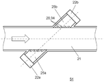
- FIG. 15 is a diagram showing a cross-sectional configuration of another example of the conventional ultrasonic flow measuring device 150.
- the ultrasonic flow rate measuring device 150 also includes recesses 125a and 125b to which the ultrasonic sensors 122a and 122b are attached.
- suppression members 124a and 124b for restricting the fluid to be measured from flowing to the sensor side are disposed at openings where the ultrasonic waves exit to the flow path (see, for example, Patent Document 2). ).
- the ultrasonic transmission members 123a and 123b and the suppression members 124a and 124b are provided in order to suppress the flow of the fluid to be measured into the recesses 125a and 125b.
- the disturbance of the flow of the fluid to be measured in the measurement part (ultrasonic wave propagation path) of the flow measurement tube 121 and the recesses 125a and 125b is reduced, and the deterioration of measurement accuracy is reduced.
- a separate member is required, there is a problem that the cost increases due to an increase in material costs and man-hours.
- the present invention has been made in view of the above-described conventional problems, and provides an ultrasonic flow measurement device that realizes stabilization of measurement accuracy and low power while suppressing an increase in cost.
- An ultrasonic flow rate measuring apparatus includes a measurement flow path through which a fluid to be measured flows, an opening formed in the measurement flow path, and a sensor mounting housing having a sensor mounting recess communicating with the opening. Yes.
- a pair of ultrasonic sensors arranged in the sensor mounting recess for measuring the flow velocity of the fluid to be measured; and a flow rate measuring unit for detecting a flow rate based on the propagation time of the ultrasonic waves between the pair of ultrasonic sensors.
- the suppression body which is provided in an opening part and suppresses the flow of the fluid to be measured to the sensor mounting recess, and the suppression body is integrally formed with the sensor mounting housing.
- the restraining body that restricts the flow into the sensor mounting recess is also molded at the same time, so there is no need to provide separate members and increase the number of assembly steps, Disturbance of the fluid to be measured that occurs in the sensor mounting recess can be suppressed, and measurement accuracy can be stabilized and power consumption can be reduced.
- FIG. 1 is a cross-sectional view showing a configuration of an ultrasonic flow rate measuring apparatus according to an embodiment of the present invention.
- FIG. 2 is a cross-sectional view of the flow rate measurement unit in the embodiment of the present invention.
- FIG. 3 is a diagram for explaining a flow rate measurement operation using ultrasonic waves in the embodiment of the present invention.
- FIG. 4 is an exploded perspective view showing the configuration of the flow rate measurement unit in the embodiment of the present invention.
- FIG. 5 is a perspective view showing a configuration of a mold for molding the sensor mounting housing in the embodiment of the present invention.
- FIG. 6 is a diagram showing the result of fluid analysis of the flow of the fluid to be measured when there is no suppressor in the opening of the ultrasonic wave propagation portion in the embodiment of the present invention.
- FIG. 1 is a cross-sectional view showing a configuration of an ultrasonic flow rate measuring apparatus according to an embodiment of the present invention.
- FIG. 2 is a cross-sectional view of the flow rate measurement unit
- FIG. 7 is a perspective view showing the configuration of the slider type in the first embodiment of the present invention.
- FIG. 8 is a perspective view showing the configuration of the sensor mounting housing according to the first embodiment of the present invention.
- FIG. 9 is a diagram showing the relationship between the sensor mounting housing and the slider type in the first exemplary embodiment of the present invention.
- FIG. 10 is a diagram showing the result of fluid analysis showing the effect of the suppressor in the first embodiment of the present invention.
- FIG. 11 is a perspective view showing a slider type configuration in the second embodiment of the present invention.
- FIG. 12 is a perspective view showing a configuration of a sensor mounting housing according to the second embodiment of the present invention.
- FIG. 13 is a diagram showing a cross-sectional configuration of another example of the ultrasonic flow rate measuring apparatus according to the second embodiment of the present invention.
- FIG. 14 is a diagram showing a cross-sectional configuration of a conventional ultrasonic flow rate measuring apparatus.
- FIG. 15 is a diagram showing a cross-sectional configuration of another example of a conventional ultrasonic flow measuring device.
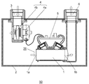
- FIG. 1 is a cross-sectional view showing a configuration of an ultrasonic flow rate measuring device 50 according to an embodiment of the present invention.
- white arrows indicate the flow of fluid (measuring fluid).
- the ultrasonic flow measuring device 50 includes a fluid supply path 3.
- the fluid supply path 3 includes a drive part 4a including an electromagnetic device such as a stepping motor and a valve body 4b linked to the drive part 4a in the middle of the flow path, and has a shut-off valve 4 opened and closed by the valve body 4b. .
- the shut-off valve 4 When the shut-off valve 4 is open, the fluid to be measured flows out from the fluid supply path 3 into the meter housing 2.
- the ultrasonic flow rate measuring device 50 includes a measurement channel 1 through which a fluid to be measured flows.
- the measurement channel 1 has a rectangular cross section.
- the fluid to be measured filled in the meter housing 2 flows into the measurement flow channel 1 from the inlet side 1a of the measurement flow channel 1, and further passes through the fluid outflow passage 6 connected to the downstream side 1b of the meter housing 2. It flows out to the outside.
- the shut-off valve 4 is set to close when there is an abnormality in the fluid flow or when an earthquake is detected by a seismic device (not shown). When the shutoff valve 4 is closed, the fluid to be measured does not flow out from the fluid supply path 3 into the meter housing 2.
- the ultrasonic flow measurement device 50 includes a flow measurement unit 26.
- FIG. 2 is a cross-sectional view of the flow rate measurement unit 26 in the embodiment of the present invention.
- a sensor mounting housing 7 is connected to the short side thereof.
- a pair of ultrasonic sensors 8 and 9 constituting a flow velocity detection unit are arranged so as to reflect and transmit / receive ultrasonic waves at the opposing wall 52.
- the ultrasonic sensors 8 and 9 are disposed in sensor mounting recesses 10 and 11 provided obliquely with respect to the measurement flow path 1.
- the ultrasonic wave is propagated in the measurement flow path 1 between the ultrasonic sensors 8 and 9 through the openings 12 and 13 formed in the measurement flow path 1 of the sensor mounting housing 7.
- a suppressing body 20 see FIG.
- the suppressing body 20 is integrally formed with the sensor mounting housing 7.
- the sensor mounting recesses 10 and 11 communicate with the openings 12 and 13.
- ultrasonic sensors 8 and 9 may be installed on the same side surface of the measurement flow path 1 and may constitute an ultrasonic propagation path using reflection on the wall surface on the opposite side. Thereby, size reduction of the measurement flow path 1 is attained.
- the driving of the ultrasonic sensors 8 and 9, the measurement of the ultrasonic propagation time, the detection of the flow rate, and the driving of the shut-off valve 4 at the time of abnormality are performed by the control unit 5 (see FIG. 1).
- FIG. 3 is a diagram for explaining a flow rate measurement operation using ultrasonic waves in the embodiment of the present invention.
- the ultrasonic sensors 8 and 9 are arranged on the same plane of the rectangular cross section of the measurement channel 1.
- the transmission / reception propagation path of the ultrasonic wave is a V-shaped propagation path reflected by the facing wall 52, and the ultrasonic wave is transmitted between the pair of ultrasonic sensors 8 and 9 arranged on the upstream side and the downstream side. Transmission / reception is performed.
- the propagation time T1 until the ultrasonic wave emitted from the upstream ultrasonic sensor 8 is received by the downstream ultrasonic sensor 9 is measured.
- the propagation time T2 until the ultrasonic wave emitted from the downstream ultrasonic sensor 9 is received by the upstream ultrasonic sensor 8 is measured.
- the flow rate is calculated by the calculation unit of the control unit 5 functioning as a flow rate measurement unit by the following calculation formula.
- the flow rate measuring unit detects the flow rate of the fluid to be measured based on the propagation time of the ultrasonic wave between the pair of ultrasonic sensors 8 and 9.
- V is the flow velocity of the fluid to be measured in the flow direction of the measurement channel 1. Further, as shown in FIG. 3, the angle between the flow direction of the measurement flow path 1 and the ultrasonic propagation path is ⁇ , and the distance of the ultrasonic propagation path between the ultrasonic sensors 8 and 9 is 2 ⁇ L, When the sound velocity of the measurement fluid is C, the flow velocity V is calculated by the following equation.
- T1 2 ⁇ L / (C + V cos ⁇ ) Equation (1)
- T2 2 ⁇ L / (C ⁇ Vcos ⁇ ) Equation (2)
- the sound velocity C is eliminated from the equation for subtracting the reciprocal of T2 from the reciprocal of T1, thereby obtaining equation (3).
- the flow velocity V (2 ⁇ L / 2 cos ⁇ ) ((1 / T1) ⁇ (1 / T2)) Equation (3)
- the angle ⁇ and the distance L are known, the flow velocity V can be calculated from the values of the propagation times T1 and T2.
- the angle ⁇ 45 degrees
- the distance L 35 mm
- the sound velocity C 340 m / s
- the flow velocity V 8 m / s
- T1 2.0 ⁇ 10 ⁇ 4 seconds
- T2 2.1 ⁇ 10 ⁇ 4 seconds
- the ultrasonic propagation path between the ultrasonic sensors 8 and 9 is not necessarily limited to the V-shaped propagation path as described above.
- the flow velocity can be measured as long as the propagation path traverses the measurement flow path 1 at least once and the propagation time of the ultrasonic wave changes due to the change in the flow velocity. .
- FIG. 4 is an exploded perspective view showing the configuration of the flow rate measurement unit 26 in the embodiment of the present invention.
- the flow rate measurement unit 26 is constituted by two molded parts, the sensor mounting housing 7 and the measurement flow path 1.
- FIG. 5 is a perspective view showing a configuration of a mold for molding the sensor mounting housing 7 in the embodiment of the present invention.
- the mold for molding the sensor mounting housing 7 includes an upper mold 14 and a lower mold 15.
- the upper mold 14 is formed with slider molds 16 and 17 for forming recesses for attaching the ultrasonic sensors 8 and 9.
- the sensor mounting recesses 10 and 11 and the openings 12 and 13 are formed by slider molds 16 and 17.
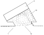
- FIG. 6 is a diagram showing the result of fluid analysis of the flow of the fluid to be measured when there is no suppressor in the opening 12 of the ultrasonic wave propagation portion in the embodiment of the present invention.
- a large vortex flow is generated in the sensor mounting recess 10 which is a space between the ultrasonic sensor 8 and the measurement flow path 1.
- the ultrasonic wave propagates through this portion, the ultrasonic wave is disturbed by the vortex flow, so that an error occurs in the measured propagation time, and accurate measurement of the flow rate passing through the measurement flow path 1 becomes difficult.
- a restraining member such as a wire mesh is separately provided in the opening connected from the sensor mounting recess 10 to the measurement flow path 1. It was. However, in this method, since it is necessary to attach a restraining member made of a separate member, there has been a strong demand to avoid as much as possible from the viewpoint of cost reduction and assembly man-hour reduction.
- the sensor mounting housing 7 in the embodiment of the present invention is manufactured using a processing method by molding. At this time, the sensor mounting recesses 10 and 11 for mounting the sensor are also integrally processed by inserting auxiliary molds called slider molds 16 and 17 into the mold for molding the sensor mounting body. It is.
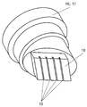
- FIG. 7 is a perspective view showing the configuration of the slider molds 16 and 17 in the first embodiment of the present invention.
- FIG. 8 is a perspective view showing the configuration of the sensor mounting housing 7 according to the first embodiment of the present invention.
- the slider molds 16, 17 have flat portions 18 at the tip portions thereof for contacting the lower mold 15 in order to form the openings 12, 13.
- the flat portion 18 is configured by a plane that is flush with the wall surface of the measurement channel 1 that is in contact with the openings 12 and 13.
- a plurality of grooves 19 are formed in the flat portion 18 in a straight line perpendicular to the flow of the fluid to be measured in the measurement flow path 1.
- the depth direction of the groove 19 is configured to be perpendicular to the ultrasonic emission surfaces of the pair of ultrasonic sensors 8 and 9.
- the suppressing body 20 is formed by a groove 19 provided at the tip of the slider molds 16 and 17.
- the suppressing body 20 can be formed. Further, the flow of the fluid to be measured can be suppressed as much as possible, and the influence on the attenuation of the ultrasonic wave propagation can be reduced.
- FIG. 9 is a diagram showing the relationship between the sensor mounting housing 7 and the slider molds 16 and 17 in the first embodiment of the present invention.
- FIG. 9 shows the relationship between the cross-sectional configuration of the sensor mounting housing 7 shown in FIG. 8 and the side views of the slider dies 16 and 17.
- the suppressing body 20 is configured at a position corresponding to the groove 19 provided in the slider molds 16, 17 of the sensor mounting housing 7 by molding with the slider molds 16, 17. Is possible.
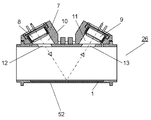
- FIG. 10 is a diagram showing the result of fluid analysis showing the effect of the suppressing body 20 in the first embodiment of the present invention.
- the groove shape in the sensor mounting recesses 10 and 11 is simply formed in the slider molds 16 and 17.
- the occurrence of inflow of the fluid to be measured can be suppressed, and the measurement accuracy can be improved.
- a separate member is not required as in the prior art, it is possible to reduce material costs and man-hours.
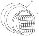
- FIG. 11 is a perspective view showing the configuration of the slider mold 32 according to the second embodiment of the present invention.
- FIG. 12 is a perspective view showing the configuration of the sensor mounting housing 7 according to the second embodiment of the present invention.
- the configuration of the ultrasonic flow rate measuring device 50 and the mold in the present embodiment is the same as that of the first embodiment except for the configuration of the slider mold 32, and thus the description thereof is omitted.
- a lattice-like groove 33 is formed at the tip of the slider mold 32.
- the groove 33 is formed in a direction perpendicular to the flow in the measurement flow path 1, and the depth direction of the groove 33 is configured to be perpendicular to the ultrasonic emission surfaces of the pair of ultrasonic sensors 8 and 9. ing.
- the sensor mounting housing 7 is molded by the same method as in the first embodiment.
- the lattice-like suppressing body 34 can be formed integrally with the sensor mounting housing 7, and the effect of suppressing the disturbance of the fluid to be measured in the further sensor mounting recesses 10 and 11 can be achieved. Obtainable.
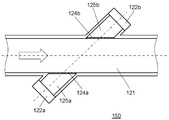
- FIG. 13 is a diagram showing a cross-sectional configuration of another example of the ultrasonic flow rate measuring device 54 according to the second embodiment of the present invention.
- the ultrasonic flow rate measuring device 54 includes a flow rate measurement tube 21 (measurement flow channel) for flowing a fluid to be measured from one to the other. Further, an ultrasonic sensor 22a is provided on the upstream side and an ultrasonic sensor 22b is provided on the downstream side, which are opposed to each other with the flow rate measuring tube 21 interposed therebetween and are inclined at a predetermined angle with respect to the center line.
- Ultrasonic sensors 22a and 22b are disposed in recesses (sensor mounting recesses) 25a and 25b provided in the flow rate measuring tube 21. It is also possible to configure the above-described suppressors 20 and 34 integrally with the flow rate measurement tube 21 in the opening portions of the recesses 25a and 25b that are in contact with the flow rate measurement tube 21. As a result, the fluid to be measured can be prevented from entering the recesses 25a and 25b, and the flow rate can be measured with high accuracy.
- the suppressing body that suppresses the flow of the fluid to be measured into the sensor mounting recess is formed at the same time as the casing. For this reason, stable measurement performance, cost reduction, and downsizing can be realized.
- the opening ratio of the opening can be increased as compared with a conventional suppression member using a wire mesh or the like. For this reason, it is difficult to obstruct the passage of ultrasonic waves, and the sensitivity is less likely to deteriorate when transmitting and receiving ultrasonic waves. Therefore, it is possible to reduce the drive input of the ultrasonic sensor and to reduce the power consumption.
- the present invention it is possible to achieve an extraordinary effect of realizing stable measurement accuracy and low power while suppressing an increase in cost. Therefore, it is useful as an ultrasonic flow rate measuring device that measures flow rates of various fluids including a gas meter.
Abstract
Description
図1は、本発明の実施の形態における超音波流量計測装置50の構成を示す断面図である。図1において、白抜きの矢印は、流体(被計測流体)の流れを示している。
T2=2×L/(C-Vcosθ) 式(2)
式(1)および式(2)において、T1の逆数からT2の逆数を引き算する式より音速Cを消去して、式(3)を得る。
ここで、角度θおよび距離Lは既知なので、伝搬時間T1およびT2の値より流速Vを算出することができる。空気の流量を計ることを考慮して、角度θ=45度、距離L=35mm、音速C=340m/s、流速V=8m/sと想定すると、T1=2.0×10-4秒、T2=2.1×10-4秒であり、瞬時計測が可能となる。
図11は、本発明の第2の実施の形態におけるスライダ型32の構成を示す斜視図である。図12は、本発明の第2の実施の形態におけるセンサ取付け筐体7の構成を示す斜視図である。
1a 入口側
1b 下流側
2 メータ筐体
3 流体供給路
4 遮断弁
4a 駆動部
4b 弁体
5 制御部
6 流体流出路
7 センサ取付け筐体
8,9,22a,22b 超音波センサ
10,11 センサ取付け窪み
12,13 開口部
14 上型
15 下型
16,17,32 スライダ型
19,33 溝
20,34 抑制体
21 流量測定管
25a,25b 凹部
26 流量計測ユニット
50,54 超音波流量計測装置
52 対向壁
Claims (7)
- 被計測流体が流れる計測流路と、
前記計測流路に形成された開口部、および、前記開口部に連通したセンサ取付け窪みを有するセンサ取付け筐体と、
前記センサ取付け窪みに配置され、前記被計測流体の流速を測定する一対の超音波センサと、
前記一対の超音波センサ間の超音波の伝搬時間に基づいて流量を検出する流量計測部と、
前記開口部に設けられ、前記センサ取付け窪みへの前記被計測流体の流入を抑制する抑制体とを備え、
前記抑制体は、前記センサ取付け筐体と一体成形された
超音波流量計測装置。 - 前記センサ取付け窪みおよび前記開口部はスライダ型で成型され、前記抑制体は、前記スライダ型の先端部分に設けられた溝によって形成される
請求項1に記載の超音波流量計測装置。 - 前記スライダ型の先端部分には、前記開口部に接する前記計測流路の壁面と同一平面となる平面を有する
請求項1に記載の超音波流量計測装置。 - 前記センサ取付け筐体および前記計測流路が一体構成である
請求項1に記載の超音波流量計測装置。 - 前記一対の超音波センサが、前記計測流路の同一側面に設置され、
対向側の壁面での反射を利用した超音波の伝搬路が構成される
請求項1に記載の超音波流量計測装置。 - 前記スライダ型の先端部分に設けられた前記溝は、前記計測流路の流れに対して垂直方向に直線状に形成され、
前記溝の深さ方向が、前記一対の超音波センサの超音波放出面に対して垂直になるよう構成される請求項2に記載の超音波流量計測装置。 - 前記スライダ型の先端の溝は、格子状であり、
前記溝は、前記計測流路内の流れに対して垂直方向に形成され、
前記溝の深さ方向は、前記一対の超音波センサの超音波放出面に対して垂直になるよう構成される請求項2に記載の超音波流量計測装置。
Priority Applications (4)
| Application Number | Priority Date | Filing Date | Title |
|---|---|---|---|
| JP2013508766A JPWO2012137489A1 (ja) | 2011-04-05 | 2012-04-04 | 超音波流量計測装置 |
| US13/984,633 US9372105B2 (en) | 2011-04-05 | 2012-04-04 | Ultrasonic flow rate measurement device |
| CN201280016739.0A CN103459988B (zh) | 2011-04-05 | 2012-04-04 | 超声波流量计测装置 |
| EP12767854.8A EP2696174A4 (en) | 2011-04-05 | 2012-04-04 | ULTRASOUND FLOWMETER |
Applications Claiming Priority (2)
| Application Number | Priority Date | Filing Date | Title |
|---|---|---|---|
| JP2011083297 | 2011-04-05 | ||
| JP2011-083297 | 2011-04-05 |
Publications (1)
| Publication Number | Publication Date |
|---|---|
| WO2012137489A1 true WO2012137489A1 (ja) | 2012-10-11 |
Family
ID=46968898
Family Applications (1)
| Application Number | Title | Priority Date | Filing Date |
|---|---|---|---|
| PCT/JP2012/002334 WO2012137489A1 (ja) | 2011-04-05 | 2012-04-04 | 超音波流量計測装置 |
Country Status (5)
| Country | Link |
|---|---|
| US (1) | US9372105B2 (ja) |
| EP (1) | EP2696174A4 (ja) |
| JP (1) | JPWO2012137489A1 (ja) |
| CN (1) | CN103459988B (ja) |
| WO (1) | WO2012137489A1 (ja) |
Cited By (2)
| Publication number | Priority date | Publication date | Assignee | Title |
|---|---|---|---|---|
| JP2014077750A (ja) * | 2012-10-12 | 2014-05-01 | Panasonic Corp | 超音波メータ |
| JP2019196968A (ja) * | 2018-05-09 | 2019-11-14 | アズビル金門株式会社 | 超音波流量計 |
Families Citing this family (15)
| Publication number | Priority date | Publication date | Assignee | Title |
|---|---|---|---|---|
| JP2012103087A (ja) * | 2010-11-10 | 2012-05-31 | Panasonic Corp | 超音波流量計測ユニット |
| BR112015003632A2 (pt) | 2012-08-22 | 2017-09-26 | Miitors Aps | medidor ultrassônico de fluxo, método de montagem de um medidor ultrassônico de fluxo. |
| JP6368916B2 (ja) * | 2015-04-16 | 2018-08-08 | パナソニックIpマネジメント株式会社 | 流量計測装置 |
| MX2018011344A (es) * | 2016-03-21 | 2019-01-31 | Envirofit Int Inc | Metodos y sistemas de distribucion de gas de petroleo licuado. |
| DK3734236T3 (da) | 2016-07-13 | 2023-08-21 | Gwf Messsysteme Ag | Flowmåler med en målekanal |
| EP3376177B1 (en) * | 2017-03-14 | 2019-11-20 | Endress + Hauser Flowtec AG | Ultrasonic flowmeter |
| US11118950B2 (en) * | 2017-04-20 | 2021-09-14 | Siemens Schweiz Ag | Ultrasonic flow meter |
| EP3633329B1 (en) * | 2017-05-22 | 2021-12-15 | Panasonic Intellectual Property Management Co., Ltd. | Gas meter |
| DE102017130976A1 (de) * | 2017-12-21 | 2019-06-27 | Endress+Hauser Flowtec Ag | Clamp-On-Ultraschall-Durchflussmessgerät und Verfahren zum Justieren des Clamp-On-Ultraschall-Durchflussmessgeräts |
| ES2930200T3 (es) * | 2018-06-08 | 2022-12-07 | Panasonic Ip Man Co Ltd | Dispositivo de seguridad de gas |
| EP3588017A1 (de) * | 2018-06-27 | 2020-01-01 | Sensus Spectrum LLC | Ultraschallmessvorrichtung |
| JP2020024180A (ja) * | 2018-08-09 | 2020-02-13 | パナソニックIpマネジメント株式会社 | 超音波流量計 |
| JP7223956B2 (ja) * | 2018-08-31 | 2023-02-17 | パナソニックIpマネジメント株式会社 | 超音波流量計 |
| CN113295222A (zh) * | 2020-02-21 | 2021-08-24 | 北京昌民技术有限公司 | 超声波流量计 |
| EP4204769A1 (de) | 2020-10-14 | 2023-07-05 | Gwf Ag | Durchflussmesser |
Citations (7)
| Publication number | Priority date | Publication date | Assignee | Title |
|---|---|---|---|---|
| JPS6326537B2 (ja) | 1978-03-01 | 1988-05-30 | Kunihiko Kanda | |
| WO2000055581A1 (fr) * | 1999-03-17 | 2000-09-21 | Matsushita Electric Industrial Co., Ltd. | Debitmetre a ultrasons |
| JP2004101542A (ja) | 1999-03-17 | 2004-04-02 | Matsushita Electric Ind Co Ltd | 超音波流量計測装置 |
| JP2006090952A (ja) * | 2004-09-27 | 2006-04-06 | Saginomiya Seisakusho Inc | 超音波流量計およびその製造方法 |
| JP2009014672A (ja) * | 2007-07-09 | 2009-01-22 | Panasonic Corp | 超音波式流体計測装置の多層流路部材 |
| JP2009288151A (ja) * | 2008-05-30 | 2009-12-10 | Ricoh Elemex Corp | 超音波流量計 |
| JP2010164558A (ja) * | 2008-12-18 | 2010-07-29 | Panasonic Corp | 流体の流れ計測装置 |
Family Cites Families (11)
| Publication number | Priority date | Publication date | Assignee | Title |
|---|---|---|---|---|
| JPS6326537A (ja) | 1986-07-18 | 1988-02-04 | Kawasaki Steel Corp | 超音波流量計 |
| ES2131672T3 (es) * | 1993-01-30 | 1999-08-01 | Kromschroeder Ag G | Medidor de flujo para fluido. |
| CN1293369C (zh) * | 1999-06-24 | 2007-01-03 | 松下电器产业株式会社 | 流量计 |
| EP1612520B1 (en) * | 2003-02-24 | 2019-01-16 | Panasonic Corporation | Ultrasonic type fluid measuring device |
| EP1610587B1 (en) * | 2003-04-28 | 2011-06-15 | Panasonic Corporation | Ultrasonic sensor |
| KR100861827B1 (ko) * | 2003-11-10 | 2008-10-07 | 마츠시타 덴끼 산교 가부시키가이샤 | 초음파 유량계와 그 제조 방법 |
| DE102004060065B4 (de) * | 2004-12-14 | 2016-10-20 | Robert Bosch Gmbh | Ultraschall Durchflussmesser mit Leitelementen |
| TW200739039A (en) * | 2005-08-12 | 2007-10-16 | Celerity Inc | Ultrasonic flow sensor |
| DE102005038599A1 (de) * | 2005-08-16 | 2007-02-22 | Robert Bosch Gmbh | Ultraschallmesseinheit mit integrierter Feuchteermittlung |
| JP4729442B2 (ja) * | 2006-06-12 | 2011-07-20 | 日立オートモティブシステムズ株式会社 | 流量測定装置,流量測定通路及びその製造方法 |
| EP2180298A4 (en) | 2007-07-09 | 2011-10-12 | Panasonic Corp | MULTILAYER CHANNEL ELEMENT FOR ULTRASONIC LIQUID MEASURING DEVICE AND ULTRASONIC LIQUID MEASURING DEVICE |
-
2012
- 2012-04-04 CN CN201280016739.0A patent/CN103459988B/zh active Active
- 2012-04-04 US US13/984,633 patent/US9372105B2/en active Active
- 2012-04-04 EP EP12767854.8A patent/EP2696174A4/en not_active Withdrawn
- 2012-04-04 WO PCT/JP2012/002334 patent/WO2012137489A1/ja active Application Filing
- 2012-04-04 JP JP2013508766A patent/JPWO2012137489A1/ja active Pending
Patent Citations (7)
| Publication number | Priority date | Publication date | Assignee | Title |
|---|---|---|---|---|
| JPS6326537B2 (ja) | 1978-03-01 | 1988-05-30 | Kunihiko Kanda | |
| WO2000055581A1 (fr) * | 1999-03-17 | 2000-09-21 | Matsushita Electric Industrial Co., Ltd. | Debitmetre a ultrasons |
| JP2004101542A (ja) | 1999-03-17 | 2004-04-02 | Matsushita Electric Ind Co Ltd | 超音波流量計測装置 |
| JP2006090952A (ja) * | 2004-09-27 | 2006-04-06 | Saginomiya Seisakusho Inc | 超音波流量計およびその製造方法 |
| JP2009014672A (ja) * | 2007-07-09 | 2009-01-22 | Panasonic Corp | 超音波式流体計測装置の多層流路部材 |
| JP2009288151A (ja) * | 2008-05-30 | 2009-12-10 | Ricoh Elemex Corp | 超音波流量計 |
| JP2010164558A (ja) * | 2008-12-18 | 2010-07-29 | Panasonic Corp | 流体の流れ計測装置 |
Non-Patent Citations (1)
| Title |
|---|
| See also references of EP2696174A4 |
Cited By (2)
| Publication number | Priority date | Publication date | Assignee | Title |
|---|---|---|---|---|
| JP2014077750A (ja) * | 2012-10-12 | 2014-05-01 | Panasonic Corp | 超音波メータ |
| JP2019196968A (ja) * | 2018-05-09 | 2019-11-14 | アズビル金門株式会社 | 超音波流量計 |
Also Published As
| Publication number | Publication date |
|---|---|
| CN103459988A (zh) | 2013-12-18 |
| EP2696174A1 (en) | 2014-02-12 |
| US9372105B2 (en) | 2016-06-21 |
| CN103459988B (zh) | 2016-08-17 |
| US20130312537A1 (en) | 2013-11-28 |
| JPWO2012137489A1 (ja) | 2014-07-28 |
| EP2696174A4 (en) | 2014-08-27 |
Similar Documents
| Publication | Publication Date | Title |
|---|---|---|
| WO2012137489A1 (ja) | 超音波流量計測装置 | |
| EP2639560B1 (en) | Ultrasonic flow rate measurement device | |
| JP2010164558A (ja) | 流体の流れ計測装置 | |
| WO2012086156A1 (ja) | 超音波流量計 | |
| WO2012164859A1 (ja) | 超音波式流量計測ユニットおよびこれを用いたガス流量計 | |
| JP2017173200A (ja) | 直管型ガスメータ | |
| WO2020044887A1 (ja) | 超音波流量計 | |
| CN106030254A (zh) | 气体流量计 | |
| JP5816831B2 (ja) | 超音波流量計 | |
| JP4936856B2 (ja) | 流量計 | |
| JP4455000B2 (ja) | ガスメータ | |
| JP2012177572A (ja) | 超音波式流体計測装置 | |
| JP6134899B2 (ja) | 流量計測ユニット | |
| JP2014077750A (ja) | 超音波メータ | |
| JP6306434B2 (ja) | 超音波流量計 | |
| JP2009264906A (ja) | 流量計 | |
| JP3922233B2 (ja) | 超音波流量計測装置 | |
| JP7373771B2 (ja) | 物理量計測装置 | |
| JP3824236B2 (ja) | 超音波流量計測装置 | |
| JP2021110685A (ja) | 超音波流量計 | |
| JP4942254B2 (ja) | ガスメータ | |
| JP2003202254A5 (ja) | ||
| JP4453341B2 (ja) | 超音波流量計 | |
| CN108700447B (zh) | 气量计 | |
| JP3436247B2 (ja) | 超音波流量計測装置 |
Legal Events
| Date | Code | Title | Description |
|---|---|---|---|
| 121 | Ep: the epo has been informed by wipo that ep was designated in this application |
Ref document number: 12767854 Country of ref document: EP Kind code of ref document: A1 |
|
| ENP | Entry into the national phase |
Ref document number: 2013508766 Country of ref document: JP Kind code of ref document: A |
|
| REEP | Request for entry into the european phase |
Ref document number: 2012767854 Country of ref document: EP |
|
| WWE | Wipo information: entry into national phase |
Ref document number: 2012767854 Country of ref document: EP |
|
| WWE | Wipo information: entry into national phase |
Ref document number: 13984633 Country of ref document: US |
|
| NENP | Non-entry into the national phase |
Ref country code: DE |