WO2012133459A1 - ヒュージブルリンクブロックの回路構成用バスバー、ヒュージブルリンクブロック、およびヒュージブルリンクブロックの製造方法 - Google Patents
ヒュージブルリンクブロックの回路構成用バスバー、ヒュージブルリンクブロック、およびヒュージブルリンクブロックの製造方法 Download PDFInfo
- Publication number
- WO2012133459A1 WO2012133459A1 PCT/JP2012/058011 JP2012058011W WO2012133459A1 WO 2012133459 A1 WO2012133459 A1 WO 2012133459A1 JP 2012058011 W JP2012058011 W JP 2012058011W WO 2012133459 A1 WO2012133459 A1 WO 2012133459A1
- Authority
- WO
- WIPO (PCT)
- Prior art keywords
- fusible
- terminal plate
- link block
- bus bar
- fusible body
- Prior art date
- Legal status (The legal status is an assumption and is not a legal conclusion. Google has not performed a legal analysis and makes no representation as to the accuracy of the status listed.)
- Ceased
Links
Images



Classifications
-
- H—ELECTRICITY
- H01—ELECTRIC ELEMENTS
- H01R—ELECTRICALLY-CONDUCTIVE CONNECTIONS; STRUCTURAL ASSOCIATIONS OF A PLURALITY OF MUTUALLY-INSULATED ELECTRICAL CONNECTING ELEMENTS; COUPLING DEVICES; CURRENT COLLECTORS
- H01R9/00—Structural associations of a plurality of mutually-insulated electrical connecting elements, e.g. terminal strips or terminal blocks; Terminals or binding posts mounted upon a base or in a case; Bases therefor
- H01R9/22—Bases, e.g. strip, block, panel
- H01R9/24—Terminal blocks
- H01R9/2425—Structural association with built-in components
- H01R9/245—Structural association with built-in components with built-in fuse
-
- H—ELECTRICITY
- H01—ELECTRIC ELEMENTS
- H01H—ELECTRIC SWITCHES; RELAYS; SELECTORS; EMERGENCY PROTECTIVE DEVICES
- H01H85/00—Protective devices in which the current flows through a part of fusible material and this current is interrupted by displacement of the fusible material when this current becomes excessive
- H01H85/02—Details
- H01H85/04—Fuses, i.e. expendable parts of the protective device, e.g. cartridges
- H01H85/05—Component parts thereof
- H01H85/055—Fusible members
- H01H85/12—Two or more separate fusible members in parallel
-
- H—ELECTRICITY
- H01—ELECTRIC ELEMENTS
- H01H—ELECTRIC SWITCHES; RELAYS; SELECTORS; EMERGENCY PROTECTIVE DEVICES
- H01H69/00—Apparatus or processes for the manufacture of emergency protective devices
- H01H69/02—Manufacture of fuses
-
- H—ELECTRICITY
- H01—ELECTRIC ELEMENTS
- H01H—ELECTRIC SWITCHES; RELAYS; SELECTORS; EMERGENCY PROTECTIVE DEVICES
- H01H85/00—Protective devices in which the current flows through a part of fusible material and this current is interrupted by displacement of the fusible material when this current becomes excessive
- H01H85/02—Details
- H01H85/04—Fuses, i.e. expendable parts of the protective device, e.g. cartridges
- H01H85/05—Component parts thereof
- H01H85/055—Fusible members
- H01H85/08—Fusible members characterised by the shape or form of the fusible member
- H01H85/10—Fusible members characterised by the shape or form of the fusible member with constriction for localised fusing
-
- H—ELECTRICITY
- H01—ELECTRIC ELEMENTS
- H01H—ELECTRIC SWITCHES; RELAYS; SELECTORS; EMERGENCY PROTECTIVE DEVICES
- H01H85/00—Protective devices in which the current flows through a part of fusible material and this current is interrupted by displacement of the fusible material when this current becomes excessive
- H01H85/02—Details
- H01H85/04—Fuses, i.e. expendable parts of the protective device, e.g. cartridges
- H01H85/05—Component parts thereof
- H01H85/055—Fusible members
- H01H85/08—Fusible members characterised by the shape or form of the fusible member
- H01H85/11—Fusible members characterised by the shape or form of the fusible member with applied local area of a metal which, on melting, forms a eutectic with the main material of the fusible member, i.e. M-effect devices
-
- H—ELECTRICITY
- H01—ELECTRIC ELEMENTS
- H01R—ELECTRICALLY-CONDUCTIVE CONNECTIONS; STRUCTURAL ASSOCIATIONS OF A PLURALITY OF MUTUALLY-INSULATED ELECTRICAL CONNECTING ELEMENTS; COUPLING DEVICES; CURRENT COLLECTORS
- H01R43/00—Apparatus or processes specially adapted for manufacturing, assembling, maintaining, or repairing of line connectors or current collectors or for joining electric conductors
- H01R43/18—Apparatus or processes specially adapted for manufacturing, assembling, maintaining, or repairing of line connectors or current collectors or for joining electric conductors for manufacturing bases or cases for contact members
-
- Y—GENERAL TAGGING OF NEW TECHNOLOGICAL DEVELOPMENTS; GENERAL TAGGING OF CROSS-SECTIONAL TECHNOLOGIES SPANNING OVER SEVERAL SECTIONS OF THE IPC; TECHNICAL SUBJECTS COVERED BY FORMER USPC CROSS-REFERENCE ART COLLECTIONS [XRACs] AND DIGESTS
- Y10—TECHNICAL SUBJECTS COVERED BY FORMER USPC
- Y10T—TECHNICAL SUBJECTS COVERED BY FORMER US CLASSIFICATION
- Y10T29/00—Metal working
- Y10T29/49—Method of mechanical manufacture
- Y10T29/49002—Electrical device making
- Y10T29/49107—Fuse making
Definitions
- the present invention mainly relates to a fusible link block interposed between an in-vehicle battery and a load side device, and more particularly to a bus bar for circuit configuration of a fusible link block, a fusible link block, and a method of manufacturing the fusible link block. Is.
- This type of fusible link block generally includes a plurality of branch circuits connected to a plurality of loads, and the circuit is protected by a fuse for each branch circuit.
- a load side terminal plate current current
- a single power source side terminal plate corresponding to an upstream terminal plate located upstream in the current flow direction
- a fusible element that performs a fuse function.
- a circuit up to a downstream terminal plate located on the downstream side in the flow direction is manufactured with a single pressed bus bar, and only necessary portions are covered with a resin housing to form a block.
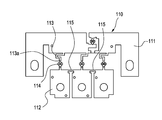
- FIG. 5 to 7 show an example of the prior art.
- FIG. 5 is a perspective view showing the shape of a conventional fusible link block circuit bus bar after pressing
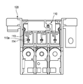
- FIG. 6 is a diagram of the conventional fusible link block.
- FIG. 7 is a front view of a fusible link block in which the bus bar of FIG. 6 is integrated with a resin housing.
- the fusible link block includes a bus bar 110 that is a circuit component and a resin housing 120 that partially covers the outer periphery of the bus bar 110 and the like.
- the bus bar 110 is connected to the power supply side terminal plate 111 via a power supply side terminal plate 111 connected to the battery and a fusible body (a portion in which the cross-sectional area through which the current passes is reduced to facilitate melting by Joule heat) 113.
- the bus bar 110 having such a branch circuit can be formed in a very compact manner because a plurality of fusible bodies 113 can be integrated and arranged, and is disclosed in Patent Document 1.
- This type of bus bar 110 is manufactured by pressing a metal plate, and is integrated with the resin housing 120 by insert molding the resin housing 120. Alternatively, it is integrated with the resin housing by press-fitting into a pre-molded resin housing.
- Each fusible body 113 is provided with a low melting point metal arrangement portion 114 at the center in the direction of current flow, and the fusing characteristics of the fusible body 113 are stabilized by caulking or welding to the arrangement portion 114.
- a low melting point metal chip such as a tin alloy is attached. Examples in which the low melting point metal is arranged at the center of the fusible body are described in Patent Document 2 and Patent Document 3.
- the bus bar 110 in which the low melting point metal is attached to the fusible body 113
- the low melting point metal when a large current of a predetermined current or more flows, the low melting point metal is melted and the low melting point metal and the fusible body 113 are eutectic and have a resistance value.
- a large alloy layer is formed, energization heat generation is promoted, and the fusible body 113 is melted.
- the overcurrent supply to the load side device is cut off by the melting of the fusible body 113.
- the fusing of the fusible body 113 occurs in the vicinity of either the upstream side or the downstream side of the low melting point metal arrangement portion 114.
- a constricted portion 113a in which the width of the fusible body 113 is locally reduced is provided on the fusible body 113 in the vicinity of the low melting point metal arrangement portion 114 at the press stage of the bus bar 110. ing.
- the constricted portion 113a is a portion that directly affects the resistance value that affects the fusing characteristics of the fusible body 113, but is weak in strength due to the small material width, and is therefore possible when affected by an external force.
- the solution 113 is easily deformed.
- joint ribs 115 are interconnected by joint ribs 115 so that an unreasonable force is not applied to the fusible body 113 when the bus bar 110 is handled as a single part.
- the joint rib 115 is left without being cut at the stage of handling as a single component, and is cut before the resin housing 120 is molded or before the bus bar 110 is press-fitted into the resin housing 120.
- the joint rib 115 must be surely cut at the product stage, so a cutting confirmation process is provided as a secondary.
- measures such as adding a product shape for confirmation are also supported.
- the joint rib 115 is conventionally provided at a position (the load side terminal plate 112) that is not related to the constricted portion 113a, the pressed portion of the constricted portion 113a and the pressed portion of the joint rib 115 are provided. Separately provided in the bus bar press mold.
- the press-processed portion of the joint rib 115 has a die shape whenever the fusing property (also referred to as rating) of the fusible body changes. There is a problem that the burden on the press die is increased.
- the present invention has been made in view of the above-described circumstances, and its purpose is to change the shape of the press die as long as there is no change other than the portion corresponding to the constricted portion of the fusible body. It is an object of the present invention to provide a fusible link circuit configuration bus bar, a fusible link block, and a fusible link block manufacturing method capable of improving production efficiency.
- a fuse integrally including an upstream terminal plate and a downstream terminal plate that is located downstream of the upstream terminal plate in the direction of current flow and is connected to the upstream terminal plate via a fusible element.
- a fusible link block circuit bus bar in which the fusing characteristics of the fusible body can be changed by changing the cutting position of the joint rib cut in the subsequent process.
- a fusible link block including a plurality of downstream terminal boards connected to the board, and a bus bar for circuit configuration integrally having a board; While the shape of each fusible body is unified, a temporary connection point is set at an intermediate portion in the current flow direction of each fusible body, and the temporary connection point of the adjacent fusible body is cut in a subsequent process.
- a low melting point metal is arranged in the middle of the current flow direction of each fusible body, the temporary connection point is set in the vicinity of the location of the low melting point metal, and the adjacent temporary connection point of the fusible body is The fusible link block according to (2), which is interconnected by the joint rib.
- a pressing step for producing the circuit configuration bus bar according to any one of (1) to (3) by pressing A housing assembly step of integrating a resin housing with the circuit configuration bus bar produced in the pressing step, and allowing the fusible body to face the window portion of the resin housing; A range from the fusible body to the downstream terminal plate by cutting the joint rib while adjusting the width of the fusible body by inserting a cutting tool through the window of the resin housing after the housing assembling step.
- Cutting step for making each electrically independent A method for manufacturing a fusible link block comprising:
- the bus bar for circuit configuration of the fusible link block having the configuration (1) the following action can be obtained. That is, for example, when the circuit configuration bus bar is handled as a single part, the downstream terminal plate connected to the upstream terminal plate via a fusible element is separated from the upstream terminal plate or the downstream terminal plate. However, if the fusible body, which is a weak weak portion due to the influence of external force, is deformed, the overall arrangement relationship may be disturbed. In a bus bar for circuit configuration of a Bulllink block, the fusible body is connected to the upstream terminal plate or the downstream terminal plate via a joint rib that is cut in a later process, so that the fusible body is deformed by the influence of external force. Can be prevented as much as possible, and the entire arrangement relationship can be prevented from being disturbed.
- the width dimension of the part corresponding to the constricted part of the fusible body can be freely adjusted by the position and dimensions of the punch that is the cutting tool, so it corresponds to the constricted part
- the fusing characteristics of the fusible body which is mainly determined by the dimensions of the portion to be performed, can be easily adjusted in the subsequent cutting step, not the circuit configuration bus bar pressing step. Therefore, it is not necessary to prepare separate press dies for pressing the circuit configuration bus bar according to the difference in the fusing characteristics of the fusible bodies, and the press dies can be unified.
- the fusing characteristics of the fusible body can be adjusted in a cutting process such as a punching process performed after the pressing process. Many different soluble variations can be made. Therefore, it is possible to significantly reduce the intermediate inventory before the cutting process.
- the joint rib's planned cutting portion can face the window portion of the resin housing, whereby, it can set so that the cutting process which cut
- the fusible link block having the configuration (2) the following action can be obtained. That is, for example, at the stage where the bus bar for circuit configuration is handled as a single part, a plurality of downstream terminal plates connected to the upstream terminal plate via a fusible element are present independently in a form separated from each other.
- the fusible link block having the above configuration (2) there is a possibility that the entire arrangement relationship may be disturbed by the deformation of the fusible body that is a strong weak part due to the influence of external force. Since each fusible body is interconnected via a joint rib that is cut in the subsequent process, it is possible to prevent deformation of each fusible body due to the influence of external force as much as possible, and to prevent the entire arrangement relationship from being disturbed. can do.
- the width dimension of the portion corresponding to the constricted portion of each fusible body can be freely adjusted according to the position and size of the punch that is the cutting tool.
- the fusing characteristics of each fusible body mainly determined by the dimensions of the portion corresponding to the constricted portion can be easily adjusted in the subsequent cutting step, not in the circuit configuration bus bar pressing step. Therefore, it is possible to unify the dimensions of the fusible body processed portion of the mold when the circuit configuration bus bar is pressed.
- the fusing characteristics of the fusible body can be adjusted in the cutting process performed after the pressing process, many possible fusing characteristics differ in the cutting process in the subsequent process while achieving a uniform shape of the fusible body in the pressing process. Variations of the solution can be made. Therefore, it is possible to significantly reduce the intermediate inventory before the cutting process.
- the joint rib's planned cutting portion can be exposed to the resin housing window.
- the cutting process for cutting the joint rib can be set to be performed at a stage after the circuit configuration bus bar is assembled to the resin housing. Therefore, the connection function by the joint rib can be left until the final stage of the manufacturing process of the fusible link block, thereby effectively preventing the fusible body from being deformed until the bus bar for circuit configuration is securely fixed by the resin housing. It is possible to improve the quality of the fusible link block.
- the fusible link block having the configuration (3) above since the low melting point metal is arranged at the center of the fusible body, the fusing characteristics of the fusible body can be stabilized.
- the joint rib is connected in the vicinity of the location where the low melting point metal is provided on the fusible body, the resistance value determined by the width of the fusible body near the location where the low melting point metal is located, that is, the fusing characteristics of the fusible body, It can be easily adjusted by changing the breaking position by the joint rib.
- the manufacturing method of the fusible link block having the above configuration (4) by changing the cutting position of the joint rib according to the position or size of the cutting tool, the fusing characteristics of the fusible body can be obtained by pressing the bus bar for circuit configuration. Instead, it can be easily adjusted in the subsequent cutting step. Accordingly, it is possible to unify the mold dimensions when pressing the circuit configuration bus bar. Moreover, since the joint rib is cut by the cutting tool after the housing assembly process for assembling the circuit configuration bus bar to the resin housing, the connection function by the joint rib remains until the final stage of the fusible link block manufacturing process. Therefore, the deformation of the fusible body can be effectively prevented until the bus bar for circuit configuration is securely fixed by the resin housing, and the quality of the fusible link block can be improved.
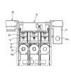
- FIG. 1 is a front view of a bus bar for circuit configuration of a fusible link block according to an embodiment of the present invention.
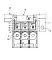
- FIG. 2 is a front view showing a state in which a resin housing is integrated with the circuit configuration bus bar of FIG. 1 by insert molding.
- FIG. 3 is a front view showing a state where a fusible link block is completed by subjecting the joint rib in the state of FIG. 2 to a cutting step and electrically separating each load side circuit.
- 4 (a) to 4 (c) are partial front views showing examples in which the width of the portion corresponding to the constricted portion of the fusible body is changed to Ha, Hb, and Hc depending on the cutting position of the joint rib. .
- FIG. 1 is a front view of a bus bar for circuit configuration of a fusible link block according to an embodiment of the present invention.
- FIG. 2 is a front view showing a state in which a resin housing is integrated with the circuit configuration bus bar of FIG. 1 by insert molding
- FIG. 5 is a perspective view showing a shape of a bus bar for circuit configuration of a conventional fusible link block after press working.
- FIG. 6 is a front view showing a state in which a low melting point metal chip (tin alloy chip) is arranged and held in the low melting point metal arrangement part of the fusible body of the circuit configuration bus bar of FIG.
- FIG. 7 is a front view showing a state in which the circuit configuration bus bar of FIG. 6 is integrated with the resin housing by insert molding.
- the fusible link block of the present embodiment includes a circuit configuration bus bar (circuit configuration bus bar) 10 manufactured by pressing one metal plate, and the bus bar.
- the resin housing 20 is formed by insert molding by setting the bus bar 10 in a mold so as to partially cover the outer periphery of the resin 10.
- the bus bar 10 includes a power source side terminal plate 11 connected to the battery and a branch circuit from the power source side terminal plate 11. And a plurality of load-side terminal plates 12 connected to the power-side terminal plate 11 via 13) that are easily melted by Joule heat.
- the power supply side terminal plate 11 corresponds to an upstream side terminal plate located on the upstream side in the current flow direction
- the load side terminal plate 12 is located on the downstream side in the current flow direction from the upstream side terminal plate. It corresponds to the downstream terminal board.
- the power supply side terminal plate 11 is provided with a connection hole 11a for connection to a power supply side terminal
- the load side terminal plate 12 is provided with a connection hole 12a for connection to a load side terminal.
- the portions where the connection holes 11a and 12a are provided and the portion where the fusible body 13 is provided are exposed from the resin housing 20, and the portions where the connection holes 12a of the load side terminal plates 12 are provided.
- the load-side terminal plate 12 and the fusible body 13 are arranged in a horizontal row, and the shapes of the fusible bodies 13 are unified into the same shape.
- a temporary connection point is set at an intermediate portion of each fusible body 13 in the current flow direction, and the temporary connection points of adjacent fusible bodies 13 are interconnected by joint ribs 15 that are cut in a subsequent process.
- the temporary connection point of the fusible body 13 adjacent to the L-shaped bent portion of the power supply side terminal plate 11 and the power supply side terminal plate 11 are also interconnected by a joint rib 15 cut in a subsequent process.
- the joint ribs 15 are arranged on a straight line.
- a low melting point metal arrangement portion 14 is provided at the center of each fusible body 13 in the direction of current flow, and a tin alloy chip (not shown) is attached to each arrangement portion 14 as a low melting point metal chip by caulking or welding. It is attached.
- the provisional connection point of the fusible body 13 is set in the vicinity of the upstream side of the low melting point metal arrangement portion 14.
- the bus bar 10 having the shape shown in FIG. 1 is manufactured by pressing in a pressing process, and the low melting point metal chip is attached to the low melting point metal arrangement portion 14. .
- the resin housing 20 is insert-molded in a state in which the bus bar 10 is set in the mold in the housing assembling process. By doing so, as shown in FIG. 2, the soluble body 13 is caused to face the second window portion 21 of the resin housing 20.
- the joint rib 15 is cut while adjusting the width of the fusible body 13 by inserting the punch 17 which is a cutting tool through the second window portion 21 of the resin housing 20.
- the range from the fusible body 13 to the load side terminal plate 12 is made electrically independent. By doing so, the fusible link block shown in FIG. 3 can be produced.
- the cut portion of the joint rib 15 is indicated by reference numeral 16.
- the width of the portion corresponding to the constricted portion is adjusted by adjusting the position and shape of the punch 17 as shown in FIGS. 4 (a) to 4 (c).
- the dimensions can be changed to Ha, Hb, and Hc (where Hb ⁇ Ha ⁇ Hc), and the fusing characteristics of the fusible body 13 can be freely adjusted.
- the width dimension Ha is a general rated current
- Hb is a low rated current
- Hc is a high rated current.
- the fusible body on the left side in the figure is for a general rated current (width dimension Ha)
- the fusible body in the center is for a low rated current (width dimension Hb)
- the fusible body is for high rated current (width dimension Hc).
- the load side terminal plate 12 connected to the power source side terminal plate 11 via the fusible element 13 is present independently in a form separated from others.
- each soluble body 13 is Since it is interconnected via the joint rib 15 that is cut in the subsequent punching process and connected to the power supply side terminal plate 11, it is possible to prevent the fusible body 13 from being deformed by the influence of external force as much as possible. It is possible to prevent the entire arrangement relationship from being disturbed.
- the width dimension of the portion corresponding to the constricted part of the fusible body 13 can be freely adjusted by the position of the punch 17 that is a cutting tool and the dimension of the punch 17. . Therefore, the fusing characteristics of the fusible body 13 mainly determined by the size of the portion corresponding to the constricted portion can be easily adjusted not in the press process of the bus bar 10 but in the punch process in the subsequent process.
- the press die can be unified.
- the dimensions of the fusible body processed portion of the press die can be unified.
- the fusing characteristics of the fusible body 13 can be adjusted in the punching process performed after the pressing process, many fusing characteristics differ in the punching process in the subsequent process while achieving a uniform shape of the fusible body 13 in the pressing process. A variation of the soluble body 13 can be produced. Therefore, it is possible to significantly compress the intermediate inventory before the punching process.
- the joint rib 15 is provided at the position of the fusible body 13, when the bus bar 10 is assembled to the resin housing 20 by insert molding or press fitting, the joint rib 15 is scheduled to be cut at the second window portion 21 of the resin housing 20. Therefore, the punching process for cutting the joint rib 15 can be set to be performed at a later stage of the housing assembly process for assembling the bus bar 10 to the resin housing 20. Therefore, the connecting function by the joint rib 15 can be left until the final stage of the manufacturing process of the fusible link block, thereby effectively preventing the fusible body 13 from being deformed until the bus bar 10 is securely fixed by the resin housing 20. The quality of the fusible link block can be improved.
- the fusing characteristics of the soluble body 13 can be stabilized. Further, since the joint rib 15 is connected in the vicinity of the low melting point metal arrangement portion 14 provided in the fusible body 13, the resistance value determined by the width dimension of the fusible body 13 in the vicinity of the low melting point metal arrangement portion 14, that is, the fusible body. The fusing characteristics of 13 can be easily adjusted by changing the breaking position by the joint rib 15.
- one of the three fusible bodies 13 is connected to the power supply side terminal plate 11 adjacent thereto via the joint rib 15.
- the fusible body 13 may be connected to the load side terminal plate 12 via the joint rib 15.
- the bus bar for circuit configuration of the fusible link block, the fusible link block, and the fusible link block manufacturing method of the present invention unless there is a change other than the portion corresponding to the constricted portion of the fusible body, There is no need to change the shape, and the production efficiency can be improved by using a mold having a uniform shape.
- Bus bar Bus bar for circuit configuration
- Power supply side terminal board upstream terminal board
- Load side terminal board downstream terminal board
- Soluble body 14
- Location of low melting point metal 15
- Joint rib 17
- Punch cutting tool
- Resin housing 21
Landscapes
- Engineering & Computer Science (AREA)
- Manufacturing & Machinery (AREA)
- Fuses (AREA)
- Connection Or Junction Boxes (AREA)
Abstract
Description
(1) 上流側端子板と、前記上流側端子板より電流の流れ方向の下流側に位置し、可溶体を介して前記上流側端子板に繋がる下流側端子板と、を一体に有したヒュージブルリンクブロックの回路構成用バスバーであって、
前記可溶体の電流の流れ方向における中間部に仮連結点が設定され、前記仮連結点と前記上流側端子板または前記下流側端子板とが、後工程にて切断されるジョイントリブにより相互連結され、前記後工程にて切断されるジョイントリブの切断位置を変えることにより前記可溶体の溶断特性が変更可能とされているヒュージブルリンクブロックの回路構成用バスバー。
前記各可溶体の形状が統一されると共に、前記各可溶体の電流の流れ方向における中間部に仮連結点が設定され、隣接する前記可溶体の仮連結点が、後工程にて切断されるジョイントリブにより相互連結され、前記後工程にて切断されるジョイントリブの切断位置を変えることにより前記可溶体の溶断特性が変更可能とされているヒュージブルリンクブロック。
前記プレス工程で作製した前記回路構成用バスバーに樹脂ハウジングを一体化して、前記樹脂ハウジングの窓部に前記可溶体を臨ませるハウジング組付け工程と、
前記ハウジング組付け工程後に前記樹脂ハウジングの窓部を通して切断工具を挿入することにより、前記可溶体の幅を調節しながら前記ジョイントリブを切断して、前記可溶体から前記下流側端子板までの範囲をそれぞれ電気的に独立させる切断工程と、
を具備するヒュージブルリンクブロックの製造方法。
図1~図3に示すように、本実施形態のヒュージブルリンクブロックは、1枚の金属板をプレス加工することで作製された回路構成用のバスバー(回路構成用バスバー)10と、このバスバー10の外周などを部分的に覆うようにバスバー10を成形型にセットしてインサート成形された樹脂ハウジング20とから構成されている。
なお、本出願は、2011年3月31日出願の日本特許出願(特願2011-079573)に基づくものであり、その内容はここに参照として取り込まれる。
11 電源側端子板(上流側端子板)
12 負荷側端子板(下流側端子板)
13 可溶体
14 低融点金属の配置箇所
15 ジョイントリブ
17 パンチ(切断工具)
20 樹脂ハウジング
21 第2窓部(窓部)
Claims (4)
- 上流側端子板と、前記上流側端子板より電流の流れ方向の下流側に位置し、可溶体を介して前記上流側端子板に繋がる下流側端子板と、を一体に有したヒュージブルリンクブロックの回路構成用バスバーであって、
前記可溶体の電流の流れ方向における中間部に仮連結点が設定され、前記仮連結点と前記上流側端子板または前記下流側端子板とが、後工程にて切断されるジョイントリブにより相互連結され、前記後工程にて切断されるジョイントリブの切断位置を変えることにより前記可溶体の溶断特性が変更可能とされているヒュージブルリンクブロックの回路構成用バスバー。 - 上流側端子板と、前記上流側端子板より電流の流れ方向の下流側に位置し、前記上流側端子板からの分岐回路を構成するためにそれぞれ可溶体を介して前記上流側端子板に繋がる複数の下流側端子板と、を一体に有した回路構成用バスバーを備えたヒュージブルリンクブロックであって、
前記各可溶体の形状が統一されると共に、前記各可溶体の電流の流れ方向における中間部に仮連結点が設定され、隣接する前記可溶体の仮連結点が、後工程にて切断されるジョイントリブにより相互連結され、前記後工程にて切断されるジョイントリブの切断位置を変えることにより前記可溶体の溶断特性が変更可能とされているヒュージブルリンクブロック。 - 前記各可溶体の電流の流れ方向の中央に低融点金属が配置され、前記低融点金属の配置箇所の近傍に前記仮連結点が設定され、隣接する前記可溶体の仮連結点が、前記ジョイントリブにより相互連結されている請求項2に記載のヒュージブルリンクブロック。
- 請求項1~3のいずれかに記載の前記回路構成用バスバーをプレス加工により作製するプレス工程と、
前記プレス工程で作製した前記回路構成用バスバーに樹脂ハウジングを一体化して、前記樹脂ハウジングの窓部に前記可溶体を臨ませるハウジング組付け工程と、
前記ハウジング組付け工程後に前記樹脂ハウジングの窓部を通して切断工具を挿入することにより、前記可溶体の幅を調節しながら前記ジョイントリブを切断して、前記可溶体から前記下流側端子板までの範囲をそれぞれ電気的に独立させる切断工程と、
を具備するヒュージブルリンクブロックの製造方法。
Priority Applications (4)
| Application Number | Priority Date | Filing Date | Title |
|---|---|---|---|
| KR1020137022832A KR101496606B1 (ko) | 2011-03-31 | 2012-03-27 | 가용성 링크 블럭 회로 형성용 버스바, 가용성 링크 블럭, 및 가용성 링크 블럭의 제조방법 |
| DE112012001481.2T DE112012001481T5 (de) | 2011-03-31 | 2012-03-27 | Sammelschiene zum Ausbilden einer Schmelzsicherungsblock- Schaltung, Schmelzsicherungsblock sowie Verfahren zum Herstellen eines Schmelzsicherungsblocks |
| CN201280011177.0A CN103415906B (zh) | 2011-03-31 | 2012-03-27 | 用于形成熔断丝块电路的汇流条、熔断丝、以及制造熔断丝的方法 |
| US13/958,882 US20130316584A1 (en) | 2011-03-31 | 2013-08-05 | Bus bar for forming fusible link block circuit, fusible link block, and method for manufacturing fusible link block |
Applications Claiming Priority (2)
| Application Number | Priority Date | Filing Date | Title |
|---|---|---|---|
| JP2011079573A JP5682067B2 (ja) | 2011-03-31 | 2011-03-31 | ヒュージブルリンクブロックの回路構成用バスバー、ヒュージブルリンクブロック、およびヒュージブルリンクブロックの製造方法 |
| JP2011-079573 | 2011-03-31 |
Related Child Applications (1)
| Application Number | Title | Priority Date | Filing Date |
|---|---|---|---|
| US13/958,882 Continuation US20130316584A1 (en) | 2011-03-31 | 2013-08-05 | Bus bar for forming fusible link block circuit, fusible link block, and method for manufacturing fusible link block |
Publications (1)
| Publication Number | Publication Date |
|---|---|
| WO2012133459A1 true WO2012133459A1 (ja) | 2012-10-04 |
Family
ID=46931171
Family Applications (1)
| Application Number | Title | Priority Date | Filing Date |
|---|---|---|---|
| PCT/JP2012/058011 Ceased WO2012133459A1 (ja) | 2011-03-31 | 2012-03-27 | ヒュージブルリンクブロックの回路構成用バスバー、ヒュージブルリンクブロック、およびヒュージブルリンクブロックの製造方法 |
Country Status (6)
| Country | Link |
|---|---|
| US (1) | US20130316584A1 (ja) |
| JP (1) | JP5682067B2 (ja) |
| KR (1) | KR101496606B1 (ja) |
| CN (1) | CN103415906B (ja) |
| DE (1) | DE112012001481T5 (ja) |
| WO (1) | WO2012133459A1 (ja) |
Cited By (3)
| Publication number | Priority date | Publication date | Assignee | Title |
|---|---|---|---|---|
| US20130181806A1 (en) * | 2010-07-29 | 2013-07-18 | Yazaki Corporation | Fuse unit |
| US20150340189A1 (en) * | 2013-02-12 | 2015-11-26 | Yazaki Corporation | Busbar |
| US9953794B2 (en) | 2015-05-29 | 2018-04-24 | Yazaki Corporation | Electric connection box and wire harness |
Families Citing this family (10)
| Publication number | Priority date | Publication date | Assignee | Title |
|---|---|---|---|---|
| JP6006134B2 (ja) * | 2013-02-08 | 2016-10-12 | トヨタ自動車株式会社 | 接続部材 |
| US9462702B2 (en) * | 2014-09-05 | 2016-10-04 | Lear Corporation | Power distribution box |
| KR20170032785A (ko) | 2015-09-15 | 2017-03-23 | 한국단자공업 주식회사 | 멀티퓨즈 |
| KR102444188B1 (ko) | 2015-12-15 | 2022-09-16 | 한국단자공업 주식회사 | 배터리 부착형 퓨즈유니트 |
| KR20170002450U (ko) | 2015-12-29 | 2017-07-07 | 한국단자공업 주식회사 | 멀티퓨즈 |
| JP6360092B2 (ja) * | 2016-03-18 | 2018-07-18 | 矢崎総業株式会社 | 電池接続モジュール、電池接続モジュールの製造方法、電池パック、および保護部材 |
| JP6340029B2 (ja) * | 2016-04-06 | 2018-06-06 | 太平洋精工株式会社 | ヒューズユニット、及びヒューズユニットの製造方法 |
| CN111095468B (zh) | 2017-09-08 | 2022-04-12 | 力特保险丝公司 | 低轮廓集成熔断器模块 |
| JP7177502B2 (ja) * | 2020-03-09 | 2022-11-24 | 太平洋精工株式会社 | 多連型ヒューズ、及び当該多連型ヒューズの製造方法 |
| JP7426088B2 (ja) * | 2020-09-09 | 2024-02-01 | 太平洋精工株式会社 | ヒューズ |
Citations (3)
| Publication number | Priority date | Publication date | Assignee | Title |
|---|---|---|---|---|
| JP2001160347A (ja) * | 1999-12-03 | 2001-06-12 | Sumitomo Wiring Syst Ltd | ヒューズ及びヒューズの製造方法 |
| JP2008226743A (ja) * | 2007-03-15 | 2008-09-25 | Taiheiyo Seiko Kk | 車両用多連型ヒューズ装置 |
| JP2010182578A (ja) * | 2009-02-06 | 2010-08-19 | Yazaki Corp | ヒューズ装置及びその製造方法 |
Family Cites Families (19)
| Publication number | Priority date | Publication date | Assignee | Title |
|---|---|---|---|---|
| US5229739A (en) * | 1992-02-21 | 1993-07-20 | Littelfuse, Inc. | Automotive high current fuse |
| JP2587911Y2 (ja) * | 1993-07-07 | 1998-12-24 | 住友電装株式会社 | 電気接続箱とミニヒューズ用バスバーの固定構造 |
| JP3226001B2 (ja) * | 1995-04-18 | 2001-11-05 | 矢崎総業株式会社 | 連鎖状ヒューズリンクおよびその形成方法 |
| US5643693A (en) * | 1995-10-30 | 1997-07-01 | Yazaki Corporation | Battery-mounted power distribution module |
| US5841338A (en) * | 1996-04-17 | 1998-11-24 | Sumitomo Wiring Systems, Ltd. | Fuse combination, method of making the same, and fuse circuit including the same |
| US5795193A (en) * | 1996-10-23 | 1998-08-18 | Yazaki Corporation | Power distribution box with busbar having bolt retaining means |
| DE59706202D1 (de) * | 1996-11-22 | 2002-03-14 | Draexlmaier Lisa Gmbh | Stromverteilungsvorrichtung |
| JPH10199396A (ja) * | 1997-01-13 | 1998-07-31 | Taiheiyo Seiko Kk | 多極型ヒューズ素子およびこの素子を使用した多極型ヒューズ |
| GB2326287B (en) * | 1997-06-09 | 2001-10-24 | Delphi Automotive Systems Gmbh | Fuse assembly |
| JP2000164111A (ja) * | 1998-03-16 | 2000-06-16 | Yazaki Corp | 自動車用大電流ヒュ―ズ |
| JP2000113803A (ja) * | 1998-10-01 | 2000-04-21 | Yazaki Corp | 自動車用大電流ヒューズ |
| JP4083991B2 (ja) * | 2000-02-09 | 2008-04-30 | 矢崎総業株式会社 | ヒューズユニットとその製造方法 |
| JP2004127698A (ja) * | 2002-10-02 | 2004-04-22 | Yazaki Corp | ヒュージブルリンクユニット |
| JP2004186006A (ja) * | 2002-12-04 | 2004-07-02 | Yazaki Corp | ヒュージブルリンク及び該ヒュージブルリンクの製造方法 |
| JP4533827B2 (ja) * | 2005-09-21 | 2010-09-01 | 矢崎総業株式会社 | ヒュージブルリンク |
| JP4769621B2 (ja) * | 2006-04-18 | 2011-09-07 | 住友電装株式会社 | 車載用電気接続箱に収容されるバスバー |
| JP4805057B2 (ja) * | 2006-08-04 | 2011-11-02 | 矢崎総業株式会社 | ヒュージブルリンクユニット |
| JP5207533B2 (ja) * | 2008-09-05 | 2013-06-12 | 矢崎総業株式会社 | 複合型ヒュージブルリンク、ヒューズボックス及びその製造方法 |
| JP5595821B2 (ja) * | 2010-07-30 | 2014-09-24 | 矢崎総業株式会社 | バスバユニット |
-
2011
- 2011-03-31 JP JP2011079573A patent/JP5682067B2/ja active Active
-
2012
- 2012-03-27 CN CN201280011177.0A patent/CN103415906B/zh active Active
- 2012-03-27 DE DE112012001481.2T patent/DE112012001481T5/de not_active Withdrawn
- 2012-03-27 KR KR1020137022832A patent/KR101496606B1/ko active Active
- 2012-03-27 WO PCT/JP2012/058011 patent/WO2012133459A1/ja not_active Ceased
-
2013
- 2013-08-05 US US13/958,882 patent/US20130316584A1/en not_active Abandoned
Patent Citations (3)
| Publication number | Priority date | Publication date | Assignee | Title |
|---|---|---|---|---|
| JP2001160347A (ja) * | 1999-12-03 | 2001-06-12 | Sumitomo Wiring Syst Ltd | ヒューズ及びヒューズの製造方法 |
| JP2008226743A (ja) * | 2007-03-15 | 2008-09-25 | Taiheiyo Seiko Kk | 車両用多連型ヒューズ装置 |
| JP2010182578A (ja) * | 2009-02-06 | 2010-08-19 | Yazaki Corp | ヒューズ装置及びその製造方法 |
Cited By (6)
| Publication number | Priority date | Publication date | Assignee | Title |
|---|---|---|---|---|
| US20130181806A1 (en) * | 2010-07-29 | 2013-07-18 | Yazaki Corporation | Fuse unit |
| US9607798B2 (en) * | 2010-07-29 | 2017-03-28 | Yazaki Corporation | Fuse unit |
| US20150340189A1 (en) * | 2013-02-12 | 2015-11-26 | Yazaki Corporation | Busbar |
| US10283308B2 (en) * | 2013-02-12 | 2019-05-07 | Yazaki Corporation | Busbar |
| DE112014000770B4 (de) * | 2013-02-12 | 2021-04-29 | Yazaki Corporation | Stromschienenvorprodukt und Stromschiene |
| US9953794B2 (en) | 2015-05-29 | 2018-04-24 | Yazaki Corporation | Electric connection box and wire harness |
Also Published As
| Publication number | Publication date |
|---|---|
| JP2012216337A (ja) | 2012-11-08 |
| JP5682067B2 (ja) | 2015-03-11 |
| KR20130126978A (ko) | 2013-11-21 |
| DE112012001481T5 (de) | 2014-01-02 |
| KR101496606B1 (ko) | 2015-02-26 |
| US20130316584A1 (en) | 2013-11-28 |
| CN103415906B (zh) | 2016-01-20 |
| CN103415906A (zh) | 2013-11-27 |
Similar Documents
| Publication | Publication Date | Title |
|---|---|---|
| JP5682067B2 (ja) | ヒュージブルリンクブロックの回路構成用バスバー、ヒュージブルリンクブロック、およびヒュージブルリンクブロックの製造方法 | |
| JP6340029B2 (ja) | ヒューズユニット、及びヒューズユニットの製造方法 | |
| JP5852744B2 (ja) | 非矩形形状を有するプロングを備えたチューニングフォーク式の電気接点 | |
| EP2019408A1 (en) | Fuse | |
| WO2012014491A1 (en) | Fuse unit | |
| JP5264376B2 (ja) | ヒューズ及びその製造方法 | |
| US20080048820A1 (en) | Fuse element and method of manufacturing the same | |
| JP6255158B2 (ja) | バスバー | |
| JP6212317B2 (ja) | ヒューズ及びヒューズの溶断特性調整方法 | |
| KR101568179B1 (ko) | 버스바 성형 다이 및 이를 이용한 버스바 제조 방법 | |
| JP3978631B2 (ja) | レアショート判断機能付き多極型ヒューズ素子、同ヒューズ及び同ヒューズの製造方法 | |
| JP6190187B2 (ja) | ヒューズユニット | |
| JP6286176B2 (ja) | ヒューズ可溶体の製造方法 | |
| JP5603699B2 (ja) | ヒューズユニット | |
| JP5774894B2 (ja) | 可溶体及び可溶体の製造方法 | |
| JP6302206B2 (ja) | ヒューズ可溶体及びその製造方法 | |
| JP2018085192A (ja) | ヒューズエレメント、および、ヒューズエレメントの製造方法 | |
| WO2014061418A1 (ja) | 電線ヒューズ | |
| WO2021166387A1 (ja) | ヒューズ、及びヒューズの製造方法 | |
| WO2022054404A1 (ja) | ヒューズ | |
| JP2008059794A (ja) | ヒューズ及びヒューズの製造方法 | |
| CN105551899A (zh) | 一种熔断器一体式接线端子的制造工艺 |
Legal Events
| Date | Code | Title | Description |
|---|---|---|---|
| 121 | Ep: the epo has been informed by wipo that ep was designated in this application |
Ref document number: 12763620 Country of ref document: EP Kind code of ref document: A1 |
|
| ENP | Entry into the national phase |
Ref document number: 20137022832 Country of ref document: KR Kind code of ref document: A |
|
| WWE | Wipo information: entry into national phase |
Ref document number: 112012001481 Country of ref document: DE Ref document number: 1120120014812 Country of ref document: DE |
|
| 122 | Ep: pct application non-entry in european phase |
Ref document number: 12763620 Country of ref document: EP Kind code of ref document: A1 |