US9462702B2 - Power distribution box - Google Patents
Power distribution box Download PDFInfo
- Publication number
- US9462702B2 US9462702B2 US14/478,439 US201414478439A US9462702B2 US 9462702 B2 US9462702 B2 US 9462702B2 US 201414478439 A US201414478439 A US 201414478439A US 9462702 B2 US9462702 B2 US 9462702B2
- Authority
- US
- United States
- Prior art keywords
- housing
- connection element
- connection
- power distribution
- distribution box
- Prior art date
- Legal status (The legal status is an assumption and is not a legal conclusion. Google has not performed a legal analysis and makes no representation as to the accuracy of the status listed.)
- Active, expires
Links
- 238000000034 method Methods 0.000 claims description 8
- 238000012986 modification Methods 0.000 description 3
- 230000004048 modification Effects 0.000 description 3
- 230000000295 complement effect Effects 0.000 description 1
- 239000004020 conductor Substances 0.000 description 1
- 239000012777 electrically insulating material Substances 0.000 description 1
- 238000003780 insertion Methods 0.000 description 1
- 230000037431 insertion Effects 0.000 description 1
- 238000012423 maintenance Methods 0.000 description 1
- 239000012858 resilient material Substances 0.000 description 1
Images


Classifications
-
- H—ELECTRICITY
- H05—ELECTRIC TECHNIQUES NOT OTHERWISE PROVIDED FOR
- H05K—PRINTED CIRCUITS; CASINGS OR CONSTRUCTIONAL DETAILS OF ELECTRIC APPARATUS; MANUFACTURE OF ASSEMBLAGES OF ELECTRICAL COMPONENTS
- H05K3/00—Apparatus or processes for manufacturing printed circuits
- H05K3/40—Forming printed elements for providing electric connections to or between printed circuits
-
- B—PERFORMING OPERATIONS; TRANSPORTING
- B60—VEHICLES IN GENERAL
- B60R—VEHICLES, VEHICLE FITTINGS, OR VEHICLE PARTS, NOT OTHERWISE PROVIDED FOR
- B60R16/00—Electric or fluid circuits specially adapted for vehicles and not otherwise provided for; Arrangement of elements of electric or fluid circuits specially adapted for vehicles and not otherwise provided for
- B60R16/02—Electric or fluid circuits specially adapted for vehicles and not otherwise provided for; Arrangement of elements of electric or fluid circuits specially adapted for vehicles and not otherwise provided for electric constitutive elements
- B60R16/023—Electric or fluid circuits specially adapted for vehicles and not otherwise provided for; Arrangement of elements of electric or fluid circuits specially adapted for vehicles and not otherwise provided for electric constitutive elements for transmission of signals between vehicle parts or subsystems
- B60R16/0239—Electronic boxes
-
- H—ELECTRICITY
- H05—ELECTRIC TECHNIQUES NOT OTHERWISE PROVIDED FOR
- H05K—PRINTED CIRCUITS; CASINGS OR CONSTRUCTIONAL DETAILS OF ELECTRIC APPARATUS; MANUFACTURE OF ASSEMBLAGES OF ELECTRICAL COMPONENTS
- H05K7/00—Constructional details common to different types of electric apparatus
- H05K7/02—Arrangements of circuit components or wiring on supporting structure
- H05K7/026—Multiple connections subassemblies
-
- H—ELECTRICITY
- H01—ELECTRIC ELEMENTS
- H01R—ELECTRICALLY-CONDUCTIVE CONNECTIONS; STRUCTURAL ASSOCIATIONS OF A PLURALITY OF MUTUALLY-INSULATED ELECTRICAL CONNECTING ELEMENTS; COUPLING DEVICES; CURRENT COLLECTORS
- H01R13/00—Details of coupling devices of the kinds covered by groups H01R12/70 or H01R24/00 - H01R33/00
- H01R13/02—Contact members
- H01R13/20—Pins, blades, or sockets shaped, or provided with separate member, to retain co-operating parts together
-
- H—ELECTRICITY
- H01—ELECTRIC ELEMENTS
- H01R—ELECTRICALLY-CONDUCTIVE CONNECTIONS; STRUCTURAL ASSOCIATIONS OF A PLURALITY OF MUTUALLY-INSULATED ELECTRICAL CONNECTING ELEMENTS; COUPLING DEVICES; CURRENT COLLECTORS
- H01R2201/00—Connectors or connections adapted for particular applications
- H01R2201/26—Connectors or connections adapted for particular applications for vehicles
-
- H—ELECTRICITY
- H01—ELECTRIC ELEMENTS
- H01R—ELECTRICALLY-CONDUCTIVE CONNECTIONS; STRUCTURAL ASSOCIATIONS OF A PLURALITY OF MUTUALLY-INSULATED ELECTRICAL CONNECTING ELEMENTS; COUPLING DEVICES; CURRENT COLLECTORS
- H01R43/00—Apparatus or processes specially adapted for manufacturing, assembling, maintaining, or repairing of line connectors or current collectors or for joining electric conductors
- H01R43/26—Apparatus or processes specially adapted for manufacturing, assembling, maintaining, or repairing of line connectors or current collectors or for joining electric conductors for engaging or disengaging the two parts of a coupling device
Definitions
- the present disclosure relates to power distribution boxes, including power distribution boxes that can be used, for example, to support a plurality of electrical components within a vehicle or a device.
- a power distribution box includes a first housing and a second housing.
- the first housing may include a first connection element
- the second housing may include a second connection element that is configured for engagement with the first connection element.
- the first and second connection elements are configured to retain the first housing relative to the second housing, and the first and second elements may be configured to electrically connect the first housing and the second housing.
- FIG. 1 is an exploded perspective view of portions of an embodiment of a power distribution box in accordance with teachings of the present disclosure.
- FIG. 2 is a partial cross-sectional perspective view of portions of an embodiment of a power distribution box in accordance with teachings of the present disclosure.
- FIG. 3 is a partial cross-sectional perspective view of portions of an embodiment of a power distribution box in accordance with teachings of the present disclosure.
- FIG. 4 is a bottom view of an embodiment of a first housing of a power distribution box in accordance with teachings of the present disclosure.
- FIG. 5 is a perspective view of portions of an embodiment of a power distribution box in accordance with teachings of the present disclosure.
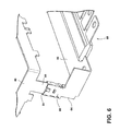
- FIG. 6 is a perspective view of portions of an embodiment of a power distribution box in accordance with teachings of the present disclosure.
- FIGS. 7A-7D are partial perspective views of portions of an embodiment of a power distribution box and a vehicle in accordance with teachings of the present disclosure.
- Power distribution box 10 may be used to support a plurality of electrical components, such as, for example, within a portion of a vehicle 92 (see, e.g., FIG. 7A ). It should be appreciated, however, that power distribution box 10 may be used in any appropriate environment and for any desired purpose.
- FIG. 1 generally illustrates an exploded view of an embodiment of a first housing 20 of a power distribution box 10 .
- First housing 20 may include relays 22 , a relay housing 24 , a circuit board 26 , electrical components 28 connected to circuit board 26 , a fuse housing 30 , fuses 32 , and/or a fuse cover 34 .
- first housing 20 may include a bus bar 40 that may be connected, physically and/or electrically, to circuit board 26 .
- Bus bar 40 may be configured to receive electrical power from second housing 60 and/or may be configured to distribute electrical power to circuit board 26 and/or other electrical components 28 .
- Bus bar 40 may also be referred to herein as a circuit board bus bar.
- Bus bar 40 may include a generally vertical portion or projection 42 that may extend (e.g., downwardly) toward second housing 60 .
- Vertical portion 42 may include a first connection element 50 .
- vertical portion 42 and/or first connection element 50 may be disposed generally in or about a corner of first housing 20 .
- bus bar 40 , vertical portion 42 , and/or first connection element may be formed as a single unitary element.
- power distribution box 10 may include first housing 20 and a second housing 60 that may be configured to be assembled together.
- an assembled configuration of first housing 20 and second housing 60 may include a cover 34 disposed between relay housing 24 , circuit board 26 , and/or fuse housing 30 on one side and second housing 60 on the other side.
- a top/exterior side 24 A of relay housing 24 may include connecting areas or portions configured for connection with wiring harness connectors 100 (e.g., as generally illustrated in FIG. 7C ).
- second housing 60 may include a bus bar, such as a pre-fuse bus bar 62 .
- Bus bar 62 may include a vertical portion 64 and/or a horizontal portion 66 .
- Horizontal portion 66 may include projections, which may extend generally horizontally for connection with pre-fuses 68 .
- Vertical portion 64 may be connected to horizontal portion 66 and may extend generally vertically upward toward first housing 20 .
- Bus bar 62 may be configured to be electrically connected, for example, with a vehicle battery 70 , which may be via one or more pre-fuses 68 .
- Pre-fuses 68 may be connected to a power source, such as a vehicle battery 70 , via one or more cables and/or wires 72 or other forms of connectors.
- pre-fuses 68 may be configured to regulate electrical power incoming to power distribution box 10 from a battery 70 .
- second housing 60 may include a second connection element 80 that may be connected to and/or formed with vertical portion 64 of bus bar 62 .
- first connection element 50 and/or second connection element 80 may include one or more of a variety of shapes, sizes, and/or configurations. First connection element 50 and second connection element 80 may be configured to cooperate and/or engage with each other.
- second connection element 80 may be configured as a female connection element, which may include being configured to receive some or all of first connection element 50 and/or vertical portion 42
- first connection element 50 may be configured as a male connection element, which may include being configured as a blade-type connector that may extend toward second connection element 80 .
- Second connection element 80 may be configured as a receptacle for a blade-type connector.
- first connection element 50 may be configured as a post-type connector and second connection element 80 may be configured to receive a post-type connector.
- at least one of first and second connection elements 50 , 80 may include a resilient portion.
- second connection element 80 may include resilient portion 90 that may be configured to be deflected upon insertion of first connection element 50 .
- resilient portion 90 may apply a spring force to first connection element 50 to retain first connection element 50 relative to second connection element 80 .
- first connection element 50 may be configured as a female connection element
- second connection element 80 may be configured as a male connection element.
- first and second connection elements 50 , 80 may not include a male-female connection, and may comprise various other forms or features for connection or attachment.
- second connection element 80 may be configured to extend outwardly (e.g., vertically upward) from second housing 60 and into at least a portion of first housing 20 .
- Second connection element 80 may include an insulating portion 82 that may electrically insulate at least a portion of second connection element 80 .
- Insulating portion 82 may comprise electrically insulating material, such as plastic.
- Insulating portion 82 may include a shape that generally corresponds to an aperture 34 A of cover 34 and/or a recess 30 A of fuse housing 30 , such that insulating portion 82 may extend into and/or through recess 30 A and/or aperture 34 A.
- insulating portion 82 may extend farther outward from second housing 60 than an electrically conducting portion 88 of second connection element 80 (e.g., insulating portion may extend into fuse housing recess 30 A, but electrically conductive portion may only extend into cover aperture 34 A). Insulating portion 82 may include an aperture 84 configured to receive a portion of first connection element 50 . In embodiments, insulating portion 82 may include a cross-sectional area that corresponds to the cross-sectional area of recess 30 A and/or aperture 34 A.
- insulating portion 82 may include a smaller cross-sectional area than aperture 84 , but may include a cross-sectional area that is substantially the same as or slightly larger than the cross-sectional area of fuse housing recess 30 A, which may correspond to an interference fit.
- bus bar 40 and/or first connection element 50 may extend through circuit board 26 and/or fuse housing 30 .
- Cover aperture 34 A may be aligned with first connection element 50 so that first connection element 50 is exposed to the exterior when first and second housings 20 , 60 are not assembled together (e.g., as generally shown in FIG. 4 ).
- second connection element 80 may extend from second housing 60 and at least partially extend into fuse housing recess 30 A and/or cover aperture 34 A.
- second connection element 80 may be welded to and/or otherwise permanently connected to bus bar 62 .
- a configuration of second connection element 80 may depend on or relate to an intended use environment of second housing 60 , such as an intended vehicle application, which may include a vehicle-specific configuration of first housing 20 (see, e.g., vehicle portion 92 in FIG. 7A ).
- first connection element 50 of first housing 20 may include one or more of a variety of configurations, and those configurations may depend on an intended use or application.
- Second connection element 80 may be configured to complement the configuration of first connection element 50 , which may permit second housing 60 to otherwise remain substantially the same for several different use environments (e.g., vehicles).
- second connection element 80 may be integrally formed with bus bar 62 and/or may include a single configuration that may be compatible with multiple configurations of first connection element 50 .
- first connection element 50 and second connection element 80 may be configured to provide an electrical connection between first housing 20 and second housing 60 , such as between bus bar 40 and bus bar 62 .
- first and second connection elements 50 , 80 may comprise one or more electrically conductive materials.
- first and second connection elements 50 , 80 may be configured to provide the sole electrical connection between first and second housings 20 , 60 , which may include providing circuit board 26 with its sole source of electrical power.
- An electrical connection provided by first and second connection elements 50 , 80 between first and second housings 20 , 60 may not include (e.g., may be independent of) wires or cables.
- An electrical connection without wires or cables may simplify assembly and disassembly, which may allow the connection to be made and/or to be disconnected manually (e.g., without any tools).
- first and second connection elements 50 , 80 may, additionally or alternatively, be configured to physically retain first housing 20 and second housing 60 relative to each other.
- first and second connection elements 50 , 80 may be configured as corresponding male and female connectors.
- Such male and female connectors may be configured such that they generally prevent substantial relative movement between first and second housings 20 , 60 in a least one direction.
- first connection element 50 is configured as a male connector and is inserted into second element, which is configured as a female connector
- first and second connection elements 50 , 80 may prevent substantial relative horizontal movement between first and second housings 20 , 60 .
- first connection element 50 and/or second connection element 80 may include a vertically retaining feature.
- first connection element 50 may include a clip 52 configured to selectively engage an aperture or recess 86 of second connection element 80 .
- Clip 52 may be configured to deflect and/or rotate in and out of recess 86 .
- Clip 52 may comprise a resilient material that may cause clip 52 to be biased into recess 86 .
- Clip 52 may prevent relative vertical movement between first and second housings 20 , 60 .
- clip 52 may be configured for manual operation, which may include being configured such that clip 52 may be rotated in and out of recess 86 without any tools.
- second connection element 80 may include clip 52 and clip 52 may selectively engage first connection element 50 .
- first connection element 50 and second connection element 80 may be the only elements that positively physically retain first and second housings 20 , 60 relative to each other. When engaged, first and second connection elements 50 , 80 may provide a sufficient retaining force to substantially maintain the assembled positions of first and second housings 20 , 60 during expected operating conditions and/or in an expected operating environment (e.g., operation of a vehicle). While first housing 20 and/or second housing 60 may include other physical retaining elements, such as tabs 74 , that may passively limit relative movement, such retaining elements may not be configured for positive engagement. Such passive retaining elements may not include movable parts and may not be actuated, moved, and/or directly interacted with by an operator during assembly or disassembly.
- first and second connection elements 50 , 80 may provide the only electrical connection and the sole positive physical connection between first and second housings 20 , 60 .
- Such a single electrical and physical connection arrangement may significantly simplify assembly and disassembly because the first and second housings 20 , 60 may be disconnected from each other via only one connection.
- several physical connections must be disengaged, sometimes simultaneously and/or with the assistance of tools, to disconnect a power distribution box 10 or portions of a power distribution box 10 from a mounting position (e.g., in a vehicle 92 ).
- several electrical connections may also need to be disconnected, usually with tools, to disconnect a first housing 20 of power distribution box 10 .
- first connection element 50 may be configured as a single projection from first housing 20 that corresponds to second connection element 80 , which may be configured as a single projection from second housing 60 and include insulating portion 82 and/or electrically conductive portion 88 .
- first and second connection elements 50 , 80 may be disposed in corresponding corners of first and second housings 20 , 60 , respectively.
- Simplified assembly may be particularly advantageous during initial assembly (e.g., on an assembly line), so that assembly time for assembly personnel and/or assembly equipment (e.g., a robot) can be reduced and/or minimized.
- second housing 60 may be configured to be mounted in a mounting location 94 , which may include in an engine compartment of a vehicle 92 .
- second housing 60 may include mounting portions 76 .
- Simplified disassembly may be particularly advantageous during maintenance, so that an operator/repair technician can quickly and manually (e.g., without tools) remove first housing 20 from a mounting location 94 .
- a method of assembly for a power distribution box 10 may include disposing second housing 60 near a mounting location 94 and then disposing second housing 60 at mounting location 94 .
- Second housing 60 may be fastened to the mounting location 94 via one or more fasteners 96 .
- first housing 20 may then be disposed generally above or over second housing 20 , which may include aligning first connection element 50 and second connection element 80 .
- first housing 20 may be moved (e.g., by applying a substantially vertically downward/perpendicular force) toward second housing 60 until first connection element 50 and second connection element 80 are fully engaged (e.g., as generally shown in FIGS. 2, 3, 5, and 6 ).
- engagement of first and second connection elements 50 , 80 may provide the only electrical connection and/or the only positive physical connection necessary between first and second housing 20 , 60 .
- Wiring harness connectors 100 may then be connected to first housing 20 , which may include moving wiring harness connectors 100 vertically downward toward first housing 20 .
- Various circuits routed to power distribution box 10 by wiring harness connectors 100 may receive power from power distribution box 10 , electrically interact with relays 22 and 32 , and/or be interconnected via circuit board 26 .
- first housing 20 may be disassembled from second housing 60 via a method corresponding to the assembly method described above.
- an operator may disengage first and second connection elements 50 , 80 , and may immediately thereafter (e.g., without disconnecting any other elements) remove first housing 20 from contact and/or connection with second housing 60 (e.g., second housing 60 may remain mounted to vehicle 92 ).
- Such disassembly may be accomplished manually, independently of tools.
- first housing 20 may remain substantially stationary during assembly and/or disassembly.
- assembly may include second housing 60 being moved toward first housing (e.g., by a substantially vertical/perpendicular force applied by an operator) to engage first and second connection elements 50 , 80 .
- Disassembly may include an operator disconnecting first and second connection elements 50 , 80 , and removing second housing 60 from any contact with first housing 20 .
- first and second housings 20 , 60 have been described as being assembled vertically/perpendicularly, embodiments of the present disclosure may include assembling first and second housings 20 , 60 horizontally (which may be perpendicularly), or at an angle with respect to the vertical 64 and/or horizontal 62 directions, depending on the positioning of second housing 60 .
Abstract
Description
Claims (20)
Priority Applications (3)
| Application Number | Priority Date | Filing Date | Title |
|---|---|---|---|
| US14/478,439 US9462702B2 (en) | 2014-09-05 | 2014-09-05 | Power distribution box |
| DE102015214763.0A DE102015214763A1 (en) | 2014-09-05 | 2015-08-03 | Power distribution box |
| CN201510551361.XA CN105406372B (en) | 2014-09-05 | 2015-09-01 | Power distribution box |
Applications Claiming Priority (1)
| Application Number | Priority Date | Filing Date | Title |
|---|---|---|---|
| US14/478,439 US9462702B2 (en) | 2014-09-05 | 2014-09-05 | Power distribution box |
Publications (2)
| Publication Number | Publication Date |
|---|---|
| US20160073520A1 US20160073520A1 (en) | 2016-03-10 |
| US9462702B2 true US9462702B2 (en) | 2016-10-04 |
Family
ID=55438878
Family Applications (1)
| Application Number | Title | Priority Date | Filing Date |
|---|---|---|---|
| US14/478,439 Active 2035-01-30 US9462702B2 (en) | 2014-09-05 | 2014-09-05 | Power distribution box |
Country Status (3)
| Country | Link |
|---|---|
| US (1) | US9462702B2 (en) |
| CN (1) | CN105406372B (en) |
| DE (1) | DE102015214763A1 (en) |
Cited By (6)
| Publication number | Priority date | Publication date | Assignee | Title |
|---|---|---|---|---|
| US20190123522A1 (en) * | 2017-10-23 | 2019-04-25 | Lear Corporation | Electrical unit |
| US10283917B1 (en) * | 2017-10-23 | 2019-05-07 | Lear Corporation | Electrical unit |
| US11025016B2 (en) | 2018-12-25 | 2021-06-01 | Lear Corporation | Electrical assembly to prevent improper installation |
| US20220200214A1 (en) * | 2020-12-22 | 2022-06-23 | Lisa Dräxlmaier GmbH | Multifunctional carrier and high voltage contactor for a battery system of an electric vehicle |
| US11419230B1 (en) * | 2021-03-18 | 2022-08-16 | Lear Corporation | Electrical unit and bushing |
| US11938876B2 (en) | 2021-08-13 | 2024-03-26 | Lear Corporation | Electrical unit |
Families Citing this family (5)
| Publication number | Priority date | Publication date | Assignee | Title |
|---|---|---|---|---|
| USD915967S1 (en) | 2016-07-22 | 2021-04-13 | Motor Coach Industries Limited | Vehicle |
| US10071698B2 (en) * | 2017-02-16 | 2018-09-11 | Motor Coach Industries Limited | Power distribution module for use in a vehicle |
| USD863227S1 (en) * | 2017-02-16 | 2019-10-15 | Motor Coach Industries Limited | Main distribution panel |
| US10787084B2 (en) * | 2017-03-17 | 2020-09-29 | Ford Global Technologies, Llc | Busbar with dissimilar materials |
| US10763629B1 (en) * | 2019-08-12 | 2020-09-01 | Lear Corporation | Integrated assembly of an electrical conductor, a fuse and a connector |
Citations (9)
| Publication number | Priority date | Publication date | Assignee | Title |
|---|---|---|---|---|
| US4390219A (en) | 1981-03-16 | 1983-06-28 | Heil-Quaker Corporation | Terminal block and capacitor mount for blower |
| US4431251A (en) | 1981-10-13 | 1984-02-14 | The Bendix Corporation | Electrical connector with a built in circuit protection device |
| US4669793A (en) * | 1985-02-05 | 1987-06-02 | Yazaki Corporation | Mating type electric connector box structure |
| US5795193A (en) | 1996-10-23 | 1998-08-18 | Yazaki Corporation | Power distribution box with busbar having bolt retaining means |
| DE10156035A1 (en) | 2000-11-17 | 2002-08-29 | Yazaki Corp | Electrical junction box |
| US6488551B1 (en) | 2000-08-17 | 2002-12-03 | Yazaki North America | Press-fit junction box terminal |
| DE102005014406A1 (en) | 2004-04-19 | 2005-11-10 | AUTONETWORKS Technologies, LTD., Yokkaichi | Electrical connector housing |
| EP1482530B1 (en) | 2003-05-24 | 2007-01-31 | LEONI Bordnetz-Systeme GmbH | Fuse box for a vehicle |
| US8690588B2 (en) | 2011-12-20 | 2014-04-08 | Yazaki North America, Inc. | Junction box assembly having an over-travel spring |
Family Cites Families (5)
| Publication number | Priority date | Publication date | Assignee | Title |
|---|---|---|---|---|
| CN201369463Y (en) * | 2009-02-10 | 2009-12-23 | 庭生工业股份有限公司 | Internal water-proof structure of power converting plug with back inserter |
| CN102237659B (en) * | 2010-04-30 | 2014-04-30 | 安泰汽车电气系统(昆山)有限公司 | Automobile junction box |
| JP5682067B2 (en) * | 2011-03-31 | 2015-03-11 | 矢崎総業株式会社 | Bus bar for fusible link block circuit configuration, fusible link block, and fusible link block manufacturing method |
| JP5875115B2 (en) * | 2012-04-18 | 2016-03-02 | 矢崎総業株式会社 | Electrical junction box |
| US9265164B2 (en) * | 2013-07-09 | 2016-02-16 | Lear Corporation | Power distribution box |
-
2014
- 2014-09-05 US US14/478,439 patent/US9462702B2/en active Active
-
2015
- 2015-08-03 DE DE102015214763.0A patent/DE102015214763A1/en active Pending
- 2015-09-01 CN CN201510551361.XA patent/CN105406372B/en active Active
Patent Citations (12)
| Publication number | Priority date | Publication date | Assignee | Title |
|---|---|---|---|---|
| US4390219A (en) | 1981-03-16 | 1983-06-28 | Heil-Quaker Corporation | Terminal block and capacitor mount for blower |
| US4431251A (en) | 1981-10-13 | 1984-02-14 | The Bendix Corporation | Electrical connector with a built in circuit protection device |
| US4669793A (en) * | 1985-02-05 | 1987-06-02 | Yazaki Corporation | Mating type electric connector box structure |
| DE3603158C2 (en) | 1985-02-05 | 1991-10-10 | Yazaki Corp., Tokio/Tokyo, Jp | |
| US5795193A (en) | 1996-10-23 | 1998-08-18 | Yazaki Corporation | Power distribution box with busbar having bolt retaining means |
| US6488551B1 (en) | 2000-08-17 | 2002-12-03 | Yazaki North America | Press-fit junction box terminal |
| DE10156035A1 (en) | 2000-11-17 | 2002-08-29 | Yazaki Corp | Electrical junction box |
| US6780026B2 (en) | 2000-11-17 | 2004-08-24 | Yazaki Corporation | Electrical junction box |
| EP1482530B1 (en) | 2003-05-24 | 2007-01-31 | LEONI Bordnetz-Systeme GmbH | Fuse box for a vehicle |
| DE102005014406A1 (en) | 2004-04-19 | 2005-11-10 | AUTONETWORKS Technologies, LTD., Yokkaichi | Electrical connector housing |
| US7283366B2 (en) | 2004-04-19 | 2007-10-16 | Autonetworks Technologies, Ltd. | Electrical connection box |
| US8690588B2 (en) | 2011-12-20 | 2014-04-08 | Yazaki North America, Inc. | Junction box assembly having an over-travel spring |
Non-Patent Citations (3)
| Title |
|---|
| English Language Abstract of DE 10 2005 014 406 A1 dated Nov. 10, 2005. |
| English Language Abstract of DE 101 56 035 A1 dated Aug. 29, 2002. |
| English Language Abstract of EP 1 482 530 (A1) dated Dec. 1, 2004. |
Cited By (7)
| Publication number | Priority date | Publication date | Assignee | Title |
|---|---|---|---|---|
| US20190123522A1 (en) * | 2017-10-23 | 2019-04-25 | Lear Corporation | Electrical unit |
| US10283917B1 (en) * | 2017-10-23 | 2019-05-07 | Lear Corporation | Electrical unit |
| US11025016B2 (en) | 2018-12-25 | 2021-06-01 | Lear Corporation | Electrical assembly to prevent improper installation |
| US20220200214A1 (en) * | 2020-12-22 | 2022-06-23 | Lisa Dräxlmaier GmbH | Multifunctional carrier and high voltage contactor for a battery system of an electric vehicle |
| US11784443B2 (en) * | 2020-12-22 | 2023-10-10 | Lisa Dräxlmaier GmbH | Multifunctional carrier and high voltage contactor for a battery system of an electric vehicle |
| US11419230B1 (en) * | 2021-03-18 | 2022-08-16 | Lear Corporation | Electrical unit and bushing |
| US11938876B2 (en) | 2021-08-13 | 2024-03-26 | Lear Corporation | Electrical unit |
Also Published As
| Publication number | Publication date |
|---|---|
| CN105406372B (en) | 2019-11-12 |
| DE102015214763A1 (en) | 2016-03-24 |
| CN105406372A (en) | 2016-03-16 |
| US20160073520A1 (en) | 2016-03-10 |
Similar Documents
| Publication | Publication Date | Title |
|---|---|---|
| US9462702B2 (en) | Power distribution box | |
| US11417968B2 (en) | Pluggable module connector and method for electrically conductively connecting at least two battery modules | |
| US9953794B2 (en) | Electric connection box and wire harness | |
| US10699866B2 (en) | Modular fuse holder and arrangement and connection thereof | |
| US6929489B2 (en) | Electric junction box | |
| JP5702314B2 (en) | Switchable fuse distribution block | |
| KR101871555B1 (en) | Electrical distribution center | |
| US20120064739A1 (en) | Receptacle with Printed Circuit Board | |
| JP5966089B2 (en) | Connector connection structure | |
| US20100173532A1 (en) | Component position assurance element for a power distribution block | |
| US20200203897A1 (en) | Electrical assembly to prevent improper installation | |
| KR20150008812A (en) | Vehicle electrical center | |
| EP2826674A2 (en) | Electrical center for a vehicle | |
| US10700320B2 (en) | Battery module | |
| CN111758143A (en) | Power distribution unit, such as a fuse box for a vehicle | |
| CN108605421B (en) | Electric wire harness connecting plate | |
| KR101934720B1 (en) | Module Type Junction Box | |
| US10044142B1 (en) | Connector locking holder | |
| US11611172B2 (en) | Busbar design that terminates with sealed connector | |
| JP6778074B2 (en) | Protective cover for battery terminals | |
| KR200474694Y1 (en) | Compact for easy parallel connection electrical and electronic equipment | |
| US9137910B2 (en) | Electrical junction box | |
| US9796346B2 (en) | Motor vehicle plastic panel having an integral electrical unit | |
| JP5798499B2 (en) | Electrical junction box | |
| JP4155927B2 (en) | Circuit breaker |
Legal Events
| Date | Code | Title | Description |
|---|---|---|---|
| AS | Assignment |
Owner name: LEAR CORPORATION, MICHIGAN Free format text: ASSIGNMENT OF ASSIGNORS INTEREST;ASSIGNORS:DARR, CHRISTOPHER J., MR.;KOWTUN, PETER, MR.;SIGNING DATES FROM 20140822 TO 20140825;REEL/FRAME:033678/0785 |
|
| AS | Assignment |
Owner name: JPMORGAN CHASE BANK, N.A., AS COLLATERAL AGENT, ILLINOIS Free format text: SECURITY INTEREST;ASSIGNOR:LEAR CORPORATION;REEL/FRAME:034695/0526 Effective date: 20141114 Owner name: JPMORGAN CHASE BANK, N.A., AS COLLATERAL AGENT, IL Free format text: SECURITY INTEREST;ASSIGNOR:LEAR CORPORATION;REEL/FRAME:034695/0526 Effective date: 20141114 |
|
| AS | Assignment |
Owner name: LEAR CORPORATION, MICHIGAN Free format text: RELEASE BY SECURED PARTY;ASSIGNOR:JPMORGAN CHASE BANK, N.A., AS AGENT;REEL/FRAME:037701/0154 Effective date: 20160104 |
|
| STCF | Information on status: patent grant |
Free format text: PATENTED CASE |
|
| MAFP | Maintenance fee payment |
Free format text: PAYMENT OF MAINTENANCE FEE, 4TH YEAR, LARGE ENTITY (ORIGINAL EVENT CODE: M1551); ENTITY STATUS OF PATENT OWNER: LARGE ENTITY Year of fee payment: 4 |
|
| MAFP | Maintenance fee payment |
Free format text: PAYMENT OF MAINTENANCE FEE, 8TH YEAR, LARGE ENTITY (ORIGINAL EVENT CODE: M1552); ENTITY STATUS OF PATENT OWNER: LARGE ENTITY Year of fee payment: 8 |