WO2012133247A1 - 印字ラベル作成装置及び切断刃受け部材 - Google Patents
印字ラベル作成装置及び切断刃受け部材 Download PDFInfo
- Publication number
- WO2012133247A1 WO2012133247A1 PCT/JP2012/057637 JP2012057637W WO2012133247A1 WO 2012133247 A1 WO2012133247 A1 WO 2012133247A1 JP 2012057637 W JP2012057637 W JP 2012057637W WO 2012133247 A1 WO2012133247 A1 WO 2012133247A1
- Authority
- WO
- WIPO (PCT)
- Prior art keywords
- tape
- cutting blade
- receiving member
- blade receiving
- Prior art date
- Legal status (The legal status is an assumption and is not a legal conclusion. Google has not performed a legal analysis and makes no representation as to the accuracy of the status listed.)
- Ceased
Links
Images





Classifications
-
- B—PERFORMING OPERATIONS; TRANSPORTING
- B26—HAND CUTTING TOOLS; CUTTING; SEVERING
- B26D—CUTTING; DETAILS COMMON TO MACHINES FOR PERFORATING, PUNCHING, CUTTING-OUT, STAMPING-OUT OR SEVERING
- B26D1/00—Cutting through work characterised by the nature or movement of the cutting member or particular materials not otherwise provided for; Apparatus or machines therefor; Cutting members therefor
- B26D1/01—Cutting through work characterised by the nature or movement of the cutting member or particular materials not otherwise provided for; Apparatus or machines therefor; Cutting members therefor involving a cutting member which does not travel with the work
- B26D1/04—Cutting through work characterised by the nature or movement of the cutting member or particular materials not otherwise provided for; Apparatus or machines therefor; Cutting members therefor involving a cutting member which does not travel with the work having a linearly-movable cutting member
- B26D1/06—Cutting through work characterised by the nature or movement of the cutting member or particular materials not otherwise provided for; Apparatus or machines therefor; Cutting members therefor involving a cutting member which does not travel with the work having a linearly-movable cutting member wherein the cutting member reciprocates
- B26D1/08—Cutting through work characterised by the nature or movement of the cutting member or particular materials not otherwise provided for; Apparatus or machines therefor; Cutting members therefor involving a cutting member which does not travel with the work having a linearly-movable cutting member wherein the cutting member reciprocates of the guillotine type
- B26D1/085—Cutting through work characterised by the nature or movement of the cutting member or particular materials not otherwise provided for; Apparatus or machines therefor; Cutting members therefor involving a cutting member which does not travel with the work having a linearly-movable cutting member wherein the cutting member reciprocates of the guillotine type for thin material, e.g. for sheets, strips or the like
-
- B—PERFORMING OPERATIONS; TRANSPORTING
- B41—PRINTING; LINING MACHINES; TYPEWRITERS; STAMPS
- B41J—TYPEWRITERS; SELECTIVE PRINTING MECHANISMS, i.e. MECHANISMS PRINTING OTHERWISE THAN FROM A FORME; CORRECTION OF TYPOGRAPHICAL ERRORS
- B41J11/00—Devices or arrangements of selective printing mechanisms, e.g. ink-jet printers or thermal printers, for supporting or handling copy material in sheet or web form
- B41J11/66—Applications of cutting devices
- B41J11/70—Applications of cutting devices cutting perpendicular to the direction of paper feed
-
- B—PERFORMING OPERATIONS; TRANSPORTING
- B26—HAND CUTTING TOOLS; CUTTING; SEVERING
- B26D—CUTTING; DETAILS COMMON TO MACHINES FOR PERFORATING, PUNCHING, CUTTING-OUT, STAMPING-OUT OR SEVERING
- B26D3/00—Cutting work characterised by the nature of the cut made; Apparatus therefor
- B26D3/08—Making a superficial cut in the surface of the work without removal of material, e.g. scoring, incising
- B26D3/085—On sheet material
-
- B—PERFORMING OPERATIONS; TRANSPORTING
- B26—HAND CUTTING TOOLS; CUTTING; SEVERING
- B26D—CUTTING; DETAILS COMMON TO MACHINES FOR PERFORATING, PUNCHING, CUTTING-OUT, STAMPING-OUT OR SEVERING
- B26D3/00—Cutting work characterised by the nature of the cut made; Apparatus therefor
- B26D3/12—Slitting marginal portions of the work, i.e. forming cuts, without removal of material, at an angle, e.g. a right angle, to the edge of the work
-
- B—PERFORMING OPERATIONS; TRANSPORTING
- B41—PRINTING; LINING MACHINES; TYPEWRITERS; STAMPS
- B41J—TYPEWRITERS; SELECTIVE PRINTING MECHANISMS, i.e. MECHANISMS PRINTING OTHERWISE THAN FROM A FORME; CORRECTION OF TYPOGRAPHICAL ERRORS
- B41J11/00—Devices or arrangements of selective printing mechanisms, e.g. ink-jet printers or thermal printers, for supporting or handling copy material in sheet or web form
- B41J11/66—Applications of cutting devices
- B41J11/70—Applications of cutting devices cutting perpendicular to the direction of paper feed
- B41J11/703—Cutting of tape
-
- B—PERFORMING OPERATIONS; TRANSPORTING
- B26—HAND CUTTING TOOLS; CUTTING; SEVERING
- B26D—CUTTING; DETAILS COMMON TO MACHINES FOR PERFORATING, PUNCHING, CUTTING-OUT, STAMPING-OUT OR SEVERING
- B26D7/00—Details of apparatus for cutting, cutting-out, stamping-out, punching, perforating, or severing by means other than cutting
- B26D2007/0012—Details, accessories or auxiliary or special operations not otherwise provided for
- B26D2007/005—Details, accessories or auxiliary or special operations not otherwise provided for cutters, e.g. guillotines, used in a label maker or printer
-
- B—PERFORMING OPERATIONS; TRANSPORTING
- B26—HAND CUTTING TOOLS; CUTTING; SEVERING
- B26D—CUTTING; DETAILS COMMON TO MACHINES FOR PERFORATING, PUNCHING, CUTTING-OUT, STAMPING-OUT OR SEVERING
- B26D5/00—Arrangements for operating and controlling machines or devices for cutting, cutting-out, stamping-out, punching, perforating, or severing by means other than cutting
- B26D5/08—Means for actuating the cutting member to effect the cut
- B26D5/10—Hand or foot actuated means
-
- B—PERFORMING OPERATIONS; TRANSPORTING
- B26—HAND CUTTING TOOLS; CUTTING; SEVERING
- B26D—CUTTING; DETAILS COMMON TO MACHINES FOR PERFORATING, PUNCHING, CUTTING-OUT, STAMPING-OUT OR SEVERING
- B26D7/00—Details of apparatus for cutting, cutting-out, stamping-out, punching, perforating, or severing by means other than cutting
- B26D7/20—Cutting beds
Definitions
- the present invention relates to a print label producing apparatus for producing a print label and a cutting blade receiving member used therefor.
- a print label producing apparatus that conveys a print-receiving tape, cuts it to a desired length, and creates a print label is known (for example, see Patent Document 1).
- the print label is produced by completely cutting the print-receiving tape printed by the printing means in the thickness direction by a cutting means (cutter).
- a cutting means cutter
- the print-receiving tape is arranged in the thickness direction.
- a half-cutting means (half-cutter) that can be cut partially is provided.
- both the means for performing normal full cutting (cutter) and the means for performing desired cutting (half cutter) are provided separately, and it is difficult to reduce the size of the apparatus.
- An object of the present invention is to provide a print label producing apparatus capable of performing both full cutting on a print-receiving tape and desired cutting in other aspects without causing an increase in size of the apparatus and an increase in manufacturing cost.
- the object is to provide a cutting blade receiving member.
- the present invention provides a conveying means for conveying a predetermined print-receiving tape along a conveying path, a printing means for performing desired printing on the print-receiving tape conveyed by the conveying means, and the conveying
- a cutting blade that moves in a direction perpendicular to the path and presses the printed tape after printing, and a cutting blade receiving member that can receive the cutting blade when the printed tape is cut by the cutting blade
- a printing label producing apparatus comprising a main body including a detachable holding portion, and at least one cutting blade receiving member, wherein the at least one cutting blade receiving member is the printing target At least one concave portion capable of receiving at least a part of the entire tape width of the tape in the tape thickness direction, and an adjacent position along the tape width direction from the concave portion.
- the first cutting blade receiving member provided with a first contact portion that receives the contact of the cutting edge of the cutting blade at the adjacent position, and the cutting edge of the cutting blade is brought into contact while sandwiching the entire tape width of the print-receiving tape.
- a second cutting blade receiving member provided with a second contact portion for receiving, wherein the holding portion of the main body of the print label producing apparatus selects the first cutting blade receiving member and the second cutting blade receiving member. It is characterized in that it is configured to be attachable.
- the print-receiving tape is transferred by the transfer means, and after the desired print is performed on the transferred print-receiving tape by the print means, the print-receiving tape is cut using a cutting blade. Is done.
- the cutting blade moves in a direction perpendicular to the conveyance path and is received by a cutting blade receiving member attached to the holding unit.
- the second cutting blade receiving member includes a second contact portion, and the second contact portion receives the contact of the cutting edge of the cutting blade while sandwiching the entire tape width of the print-receiving tape during the cutting operation of the cutting blade. .
- the cutting blade can completely cut the print-receiving tape in the thickness direction.
- the first cutting blade receiving member includes at least one concave portion and a first contact portion.
- the recess receives at least a part of the entire tape width of the print-receiving tape in the tape thickness direction.
- a 1st contact part is provided in the adjacent position of a recessed part along a tape width direction, and receives the blade edge
- a cutting blade cuts
- the cutting blade is partially cut in the thickness direction (so-called semi-cutting) or not cut for the portion of the tape to be printed that is received in the recess, because the cutting edge does not sufficiently reach. It can be.
- the normal print-receiving tape when the second cutting blade receiving member is mounted, the normal print-receiving tape can be completely cut, and when the first cutting blade receiving member is mounted, at least a part of the print-receiving tape is used.
- the desired desired mode of cutting can be performed in such a manner that is half-cut (or non-cut). That is, it is possible to perform both full cutting and desired cutting by using the same cutting blade only by exchanging the cutting blade receiving member attached to the holding portion.
- size reduction of a device and reduction of manufacturing cost can be aimed at.
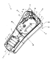
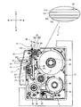
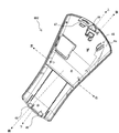
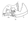
- FIG. 1 is a perspective view illustrating an overall configuration of a print label producing apparatus according to an embodiment of the present invention. It is a perspective view showing the internal structure of the print label producing apparatus in a state where the detachable cover is removed and the cartridge and the dry battery are mounted in the cartridge holder and the battery storage unit. It is a perspective view showing the internal structure of the print label producing apparatus in a state where the detachable cover is removed and the cartridge and the dry battery are removed from the cartridge holder and the battery storage unit. It is a top view showing the internal structure of a cartridge with a roller holder, a rib, a heat sink, a thermal head, etc. It is a perspective view showing the front surface of a detachable cover.
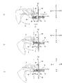
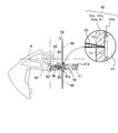
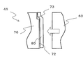
- FIG. 4 is a diagram illustrating a state where the tip of the cutter blade is in contact with a cutter blade receiving member. It is explanatory drawing explaining the half cutting operation
- FIG. 14 is a cross-sectional view taken along a line PP ′ in FIG. 13 and a cross-sectional view taken along a line QQ ′. It is a conceptual sectional view showing the behavior which performs desired cutting using the 1st cutter blade receiving part in the modification which leaves only the tape width direction both ends and cuts only the center side. It is the upper side figure and bottom view showing the external appearance of an example of the printed label continuous body formed by completing the desired cutting by the first cutter blade receiving part and the entire cutting by the second cutter blade receiving part. It is a conceptual sectional view showing the behavior which performs desired cutting using the 1st cutter blade receiving part in the modification which leaves only the tape width direction center side and cuts only both ends.
- the print label producing apparatus 1 is a handy type print label producing apparatus held by an operator's hand.
- the casing 6 of the print label producing apparatus 1 is composed of a front cover 6A that constitutes the front face of the apparatus and a rear cover 6B that constitutes the rear face of the apparatus.
- the rear cover 6B includes a rear cover body 6B1 incorporating various mechanisms, and a detachable cover 6B2 that can be detached from the rear cover body 6B1 when the cartridge 31 and the dry battery 8 (see FIG. 2 described later) are attached and detached. It consists of
- a liquid crystal display unit (not shown) for displaying print data, a setting screen, and the like is provided on the upper side of the front cover 6A.
- the front surface of the liquid crystal display unit is covered with a cover panel 2A made of, for example, a transparent acrylic plate.
- a keyboard unit 3 for operating the print label producing apparatus 1 is provided below the liquid crystal display unit.
- the keyboard unit 3 includes character keys such as characters, symbols and numbers, and various function keys.
- a cut lever 4 (operating lever) for cutting the printed label tape 80 (see FIG. 4 described later) is provided at the upper right side of the rear cover body 6B1.
- a frame 13 formed of resin is disposed inside the front cover 6A and the rear cover body 6B1.
- the cartridge holder 7 having a rectangular shape in plan view formed in a concave shape for attaching and detaching the cartridge 31 is provided on the upper rear side of the frame 13.
- a motor storage 5 for storing a motor (not shown).
- the battery storage unit 9 for storing the dry batteries 8 is provided further below the motor storage unit 5.
- a tape discharge slit 24 for discharging the printed label tape 80 (see FIG. 4 described later) to the outside is formed on the upper portion of the frame 13.
- a roller holder 17 (detailed structure will be described later) is provided on the upper right side of the frame 13.
- a plate portion 25 made of synthetic resin having a plate shape is provided so as to cover the roller holder 17.
- the plate portion 25 is formed integrally with the frame 13.
- a protrusion insertion port 10 that is an opening is provided on the upper portion of the plate portion 25.
- a lock hole 11 is provided at the upper end of the rear cover body 6B1, and two lock holes 12 are provided at the lower end.
- a gear recess 26 formed in a concave shape is provided at a substantially central portion of the frame 13.
- the gear recess 26 is provided with a gear (not shown), and the gear tooth portion is covered with the concealing umbrella portion 114 and is not exposed.
- a ribbon take-up shaft 14 for taking up an ink ribbon 55 is provided upright on the rear side of the gear.
- the gears and a plurality of gears (not shown) provided on the front side of the frame 13 meshing with the gears are each formed of a synthetic resin, and a gear shaft (not shown) that rotatably supports these gears. ) Is also formed of a synthetic resin, and is formed integrally with the frame 13.
- a rib 30 is erected on the right side of the ribbon take-up shaft 14.
- a heat sink 15 which is a rectangular heat sink is provided on the right side surface of the rib 30.
- a roller shaft 20 is erected between the rib 30 and the tape discharge slit 24.
- the roller shaft 20 is made of synthetic resin and is formed integrally with the frame 13.
- a convex portion 27 is erected on the left side of the roller shaft 20. The convex portion 27 is inserted into a concave portion (not shown) of the cartridge 31 to position the cartridge 31 in the front-rear direction.
- a guide holder 40 that houses a cutter holder 60 (see FIG. 5 to be described later) having a cutter blade 63 (see FIG. 11 to be described later) is provided in the frame 13 in the vicinity of the tape discharge slit 24. Yes. Further, a cutter blade receiving member 41 is provided on the left side of the guide holder 40 in the vicinity of the tape discharge slit 24 in the frame 13. The cutter blade receiving member 41 is for receiving the cutter blade 63 when the printed label tape 80 is cut by the cutter blade 63.
- the cut lever 4 is supported so as to be rotatable with respect to the frame 13 (with a lever shaft 65 described later as an axis), and the cutter blade 63 can be moved.
- the first rib rib 42 and the holding portion 76 are integrally formed with the frame 13 in the vicinity of the tape discharge slit 24.
- the rib 42 formed on the right side of the tape discharge slit 24 is erected vertically with respect to the planar rear surface portion 25A of the plate portion 25.
- the holding portion 76 formed on the left side of the tape discharge slit 24 is erected on the left side of the cutter blade receiving member 41 and holds (attaches) the cutter blade receiving member 41.
- a cover film spool 52 around which a transparent film-like cover film 51 is wound is rotatably arranged at the lower left side in the cartridge case 33.
- the cover film 51 fed out from the cover film spool 52 is guided toward the cartridge opening 371 and sent out from the cartridge opening 371.
- a ribbon spool 56 around which an ink ribbon 55 is wound is rotatably arranged at the lower right side in the cartridge case 33.
- the ink ribbon 55 fed out from the ribbon spool 56 is guided toward the cartridge opening 371 and delivered together with the cover film 51.
- a ribbon take-up spool 57 is rotatably arranged between the cover film spool 52 and the ribbon spool 56.
- the ribbon take-up spool 57 pulls out the ink ribbon 55 from the ribbon spool 56 and winds up the ink ribbon 55 consumed by printing (printing) characters or the like.
- a base tape spool 54 around which a base tape 53 is wound is rotatably disposed in the upper part of the cartridge case 33.
- the base tape 53 has a four-layer structure (see a partially enlarged view in FIG. 4), and extends from the side wound radially inward (lower side of the enlarged view) to the opposite side (upper side of the enlarged view).
- an adhesive layer 53a made of an appropriate adhesive
- a colored base film (base material layer) 53b made of PEL (polyethylene terephthalate)
- an adhesive layer (adhesive layer) 53c made of an appropriate adhesive
- release paper The release material layer 53d is laminated in the order of 53d.
- the base tape 53 fed out from the base tape spool 54 is guided toward the tape transport roller 39, and the base tape 53 and the printed cover film 51 are connected to the tape transport roller 39 and the pressure roller 192.
- the pressure-sensitive adhesive layer 53a is pressure-bonded to form a printed label tape 80, which is conveyed toward the label tape discharge port 59.
- an arm-shaped roller holder 17 having a platen roller unit 18 and a pressing roller unit 19 can swing in the left-right direction around the shaft support portion 171.
- the roller holder 17 is also made of a synthetic resin like the frame 13.
- the platen roller unit 18 is disposed on the right side of the heat sink 15.
- the platen roller unit 18 is provided with a platen roller 182 and a platen roller gear (not shown).
- the platen roller 182 is disposed at a position facing the thermal head 16 provided on the right side surface of the heat sink 15.
- the thermal head 16 performs desired printing on the cover film 51 transported along the transport path by the pressing roller 192, the platen roller 182 and the like.
- the platen roller gear is meshed with a gear (not shown) provided on the front side of the frame 13, and the platen roller gear 182 is rotated by the rotation of the platen roller gear to which power is transmitted from the motor.
- the platen roller 182 presses the cover film 51 and the ink ribbon 55 against the thermal head 16, and characters, figures, symbols, etc. are printed.
- the cover film 51 is conveyed in the direction of the pressing roller unit 19 by its rotation.
- the pressing roller unit 19 is provided with a pressing roller 192 and a pressing roller gear (not shown).
- the pressing roller 192 is disposed at a position facing the roller shaft 20, and the transport path (arrows A, I) for the cover film 51, the base tape 53, and the printed label tape 80 to the tape discharge slit 24. , See c).
- the roller shaft 20 includes a cylindrical portion 201 formed in a cylindrical shape and six ribs 202 formed radially from the outer periphery of the cylindrical portion 201 to the outside.
- the roller shaft 20 is inserted into a shaft hole 391 of a tape transport roller 39 provided in the cartridge 31, and rotatably supports the tape transport roller 39.
- the pressure roller gear meshes with a gear (not shown) provided on the front side of the frame 13, and the pressure roller 192 is rotated by rotation of the pressure roller gear to which power is transmitted from the motor. .
- the pressing roller unit 19 moves to the printing position, the pressing roller 192 presses the cover film 51 and the base tape 53 against the tape transport roller 39 that is rotatably supported by the roller shaft 20. To do.
- the printed cover film 51 and the base tape 53 are pressure-bonded to form a printed label tape 80, which is discharged from the label tape discharge port 59.
- the transport path of the printed label tape 80 (in other words, the transport path of the cover film 51; the same applies hereinafter) is performed by the pressure roller 192 and the guide holder 40 and the cutter blade receiving member 41 (see FIG. 2 and the like).
- the cutter blade 63 cuts the printed label tape 80 (or semi-cuts, details will be described later).
- the cutter blade 63 moves in a direction (C direction in FIG. 11 to be described later) orthogonal to the conveyance path, and the cutter blade receiving member 41 mounted on the holding unit 76. The cutting (or semi-cutting) is performed by being received by.
- the detachable cover 6B2 will be described with reference to FIG.
- the above-described lock member 47 is erected at the upper left end portion of the front surface 6a of the detachable cover 6B2, and the above-described two lock members 48 are erected at the lower end portion.
- the lock members 47 and 48 are fitted in the lock holes 11 and 12 (see FIG. 2 and the like) provided in the rear cover body 6B1, respectively. Thereby, the natural opening of the detachable cover 6B2 is prevented.
- a protrusion 45 is erected perpendicularly to the front surface 6a of the detachable cover 6B2 on the upper right side of the front surface 6a of the detachable cover 6B2.
- the protrusion 45 is inserted into and extracted from the protrusion insertion port 10 (see FIG. 2 and the like) provided in the rear cover body 6B1.
- the roller holder 17 can be moved to the printing position (position shown in FIG. 4) or moved to the standby position (position shown in FIG. 3).
- the protrusion 45 has a rib 42 (which is formed integrally with the frame 13) in a state where the detachable cover 6B2 is attached to the rear cover body 6B1 (in other words, a state where it is attached to the frame 13, the same applies hereinafter). 3) can be supported from the right side of the rib 42.
- a support rib 46 is erected vertically on the front surface 6a of the detachable cover 6B2 so as to be perpendicular to the front surface 6a of the detachable cover 6B2.
- the support rib 46 can support the holding portion 76 (see FIG. 3) formed integrally with the frame 13 from the left side of the holding portion 76 in a state where the detachable cover 6B2 is attached to the rear cover body 6B1. It has become. Note that the support rib 46 may be omitted when the holding portion 76 can sufficiently tolerate a reaction force from the printed label tape 80 during full cutting or half cutting (described later).
- the printed label is obtained by mounting one common cutter blade receiving member 41 having different shapes on one side and the other side to the holding portion 76 while changing the direction. Both normal full cutting and half cutting (described later) can be performed on the tape 80 for use. Hereinafter, the details will be described in order.
- a rectangular plate-like holding portion 76 is erected (integrated with the frame 13).
- the cutter blade receiving member 41 is formed in a square bag shape in this example, and the holding portion 76 (see FIG. 7) is inserted through the insertion hole 74 formed in the bottom. 6) and is detachably fitted and held.
- a horizontally-long rectangular locking hole 76A (see FIG. 6) is provided through both front and rear surfaces of the holding portion 76.
- the cutter blade receiving member 41 has elastic hook pieces 75 (lower and lower front and rear edges of the insertion hole 74) projecting so as to face each other on the insertion hole 74 side of the cutter blade receiving member 41 so as to correspond to the locking hole 76A. (See FIG. 7 (a) and FIG. 7 (b)). Accordingly, for example, when the operator holds the side blade 70 and fits the cutter blade receiving member 41 to the holding portion 76, the pair of front and rear elastic hook pieces 75 on the insertion hole 74 side of the cutter blade receiving member 41. Is engaged and held in the locking hole 76A of the holding portion 76.
- the tip of the elastic hook piece 75 rides on the wall surface, and the elastic hook piece 75 expands elastically. As a result, the cutter blade receiving member 41 is detached from the holding portion 76.
- the cutter blade receiving member 41 includes the first cutter blade receiving portion 41a on one side (the left rear side in FIG. 7A and the right front side in FIG. 7B) and the other side ( It is configured as one common cutter blade receiving member provided with a second cutter blade receiving portion 41b on the right front side in FIG. 7A and the left rear side in FIG. 7B.
- the cutter blade receiving member 41 is mounted on the holding portion 76 so that the first cutter blade receiving portion 41a side faces the transport path of the printed label tape 80 (see FIG. 7B and FIG. 12 described later). Or attached to the holding portion 76 so that the second cutter blade receiving portion 41b side faces the transport path of the printed label tape 80 (FIG. 7 (a) and FIGS. 11 (a) to 11 (to be described later)). (See (c)).
- the second cutter blade receiving portion 41 b includes a second contact portion 71.
- the second contact portion 71 is made of resin.
- the printed label tape 80 the cover film 51, the adhesive layer 53a, the base
- the contact of the cutting edge of the cutter blade 63 is received while sandwiching the entire tape width of the film 53b, the adhesive layer 53c, and the release paper 53d).
- the cutter blade 63 can completely cut the printed label tape 80 in the thickness direction.
- the first cutter blade receiving portion 41 a includes a recess 73 and two first contact portions 72.
- the recess 73 receives the entire tape width of the cover film 51 in the tape thickness direction.
- the 1st contact part 72 is comprised with the metal in this example, is provided in the both-sides adjacent position of the recessed part 73 along the tape width direction, and receives the blade edge
- the cutter blade 63 does not reach the cutting edge sufficiently to the entire dimension in the thickness direction of the printed label tape 80 received in the concave portion 63 of the cover film 51, and as a result, the cutter blade 63 partially in the thickness direction. It will cut
- the depth direction dimension d of the recess 73 is set in advance to be equal to the thickness direction dimension t of the release paper 53d.
- the cutter blade 63 can cut other portions (the cover film 51, the adhesive layer 53a, the base film 53b, and the adhesive layer 53c) of the printed label tape 80 while leaving the release paper 53d. .
- the setting of the depth direction dimension d of the recessed part 73 is not restricted above. It may be smaller than the dimension t in the thickness direction of the release paper 53d. In that case, a part of the dimension in the thickness direction can be cut also about the release paper 53d. Conversely, it may be larger than the thickness direction dimension t of the release paper 53d. In that case, by setting the dimension d in the depth direction, the remaining layers of the printed label tape 80, that is, up to which layer of the cover film 51, the adhesive layer 53a, the base film 53b, and the adhesive layer 53c are cut, Which layer is left (uncut) can be appropriately set to a desired mode.
- FIGS. 11A to 11C show the cutter button 4, the guide holder 40, and the cutter blade receiving member 41 in the vicinity of the tape discharge slit 24 in a state where the removable cover 6B2 is removed from the print label producing apparatus 1. Corresponds to a view seen through from the rear side.
- the operator when performing full cutting, as described above, the operator can attach the second cutter blade receiving portion 41b to the printed label tape 80.
- the cutter blade receiving member 41 is attached to the holding portion 76 so as to be on the conveyance path side.
- the cut lever 4 is supported so as to be rotatable with respect to the frame 13 about a lever shaft 65 formed on the frame 13.
- the printed label tape 80 discharged from the label tape discharge port 59 (see FIG. 4) is guided along the conveyance path by the pressing roller 192 (see FIG. 4) or the like.
- the cutter blade receiving member 41 are conveyed from the bottom to the top. Then, it is guided to the tape discharge slit 24 and discharged (a part thereof) from the tape discharge slit 24 to the outside of the print label producing apparatus 1 to be in the state shown in FIG.
- the cut lever 4 is in the initial position (the position shown in FIG. 11A). Located in. When located at this initial position, the contact portion 4 ⁇ / b> A of the cut lever 4 is separated from the contact convex portion 62.
- the cut lever 4 rotates in the lever rotation direction R about the lever shaft 65.
- the contact portion 4A of the cut lever 4 contacts the contact convex portion 62.
- the contact portion 4A causes the cutter holder 60 to be attached to the printed label tape 80 via the contact convex portion 62 that is in contact. Is moved in the direction of arrow C (leftward) perpendicular to the transport path.
- the cutter blade 63 also moves in the direction of arrow C.
- the direction of the arrow C corresponds to the “direction perpendicular to the transport path” described in each claim.
- the cutter blade 63 gradually presses the printed label tape 80 and finally comes into contact with the cutter blade receiving member 41 (the state shown in FIG. 11C).
- the cutter blade 63 completely removes the printed label tape 80 over the entire thickness direction by the pressing force generated between the cutter blade 63 and the cutter blade receiving member 41 based on the turning operation of the cut lever 4. It can be pushed out (see FIG. 9).
- the printed label tape 80 received and entered into the concave portion 73 is shifted to the front side in the traveling direction as viewed from the cutter blade 63.
- the front end of the cutter blade 63 is printed at a timing later than that at the time of full cutting in FIGS. 11A to 11C (in other words, with a larger amount of operation of the cut lever 4 than at the time of full cutting).
- the cutter blade 63 gradually pushes the printed label tape 80 in contact with the tape 80 for printing.
- the cutter blade 63 comes into contact with the first contact portion 72 of the first cutter blade receiving portion 41a.
- the cutter blade 63 is a portion of the printed label tape 80 excluding the release paper 53, that is, the cover film 51 and the adhesive layer 53a, by the pressing force generated between the cutter blade 63 and the cutter blade receiving member 41.
- the base film 53b and the adhesive layer 53c are pushed all over the thickness direction (see FIG. 10).
- the cutter blade receiving member 41 has a fixed structure at any point in the cutting operation when the printed label tape 80 is completely cut and half cut by the cutter blade 63 due to the locking structure to the holding portion 76 described above. It rarely moves from position.
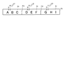
- Print label L An example of the print label L created by the operator while changing the orientation of the cutter blade receiving member 41 as described above will be described with reference to FIGS. 13 and 14.
- a print label continuous body including three print labels L1, L2, and L2 is created.
- These printed labels L1, L2, and L3 are formed by completing the cutting or semi-cutting of the printed label tape 80 as described above, and the cover film has the four-layer structure shown in FIG. A five-layer structure with 51 added (see FIG. 14A). That is, from the cover film 51 side (upper side in FIG. 14A) toward the opposite side (lower side in FIG. 14A), the cover film 51, the adhesive layer 53a, the base film 53b, the adhesive layer 53c, and the peeling The paper 53d constitutes five layers. And the printing R is printed on the back surface of the cover film 51, respectively.
- the cutter blade receiving member 41 is mounted so that the first cutter blade receiving portion 41a is on the conveyance path side of the printed label tape 80, and the cutter blade 63 is half-finished.
- a print label L1 having a print R of “ABC” and a print label L2 having a print R of “DEF” are created.
- the rear end portion in other words, the boundary portion with the print label L2 on the upstream side in the conveyance direction of the print label L1 (in other words, the boundary portion with the print label L2) is the release paper 53 of the printed label tape 80 which is the result of the half-cut.
- cover film 51, the adhesive layer 53a, the base film 53b, and the adhesive layer 53c are divided into half cut portions HC (see FIG. 14B).
- the cutter blade receiving member 41 is replaced so that the second cutter blade receiving portion 41b is on the side of the transport path of the printed label tape 80, and the cutter blade 63 performs a half-cut state as “GHI”.
- a print label L3 having a print R of "" is created.
- the rear end portion on the upstream side in the transport direction of the print label L3 (in other words, the rear end portion of the print label continuous body) is divided by all the layers of the printed label tape 80, which is the result of the above-described complete cutting.
- the full cut line CL is made.
- the printed label tape 80 is cut to a predetermined length by the cooperation of the cutter blade 63 and the cutter blade receiving member 41.
- a print label L having a desired print R is created.
- the cutter blade receiving member 41 is configured to be detachable from the holding portion 63.
- the printed label tape 80 can be completely cut. it can.
- the cutter blade receiving member 41 By attaching the cutter blade receiving member 41 to the holding portion 63 so that the first cutter blade receiving portion 41a faces the conveyance path side of the printed label tape 80, the printed label tape 80 can be cut in half. it can. That is, by simply changing the cutter blade receiving member 41 attached to the holding portion 76 in the opposite direction, both the full cutting and the desired cutting (half cutting in this example) are performed using the same one cutter blade 63. Can be executed. Thereby, compared with the conventional structure which needed to install both the cutting device for full cutting, and the cutting device for desired cutting, size reduction of a device and reduction of manufacturing cost can be aimed at.
- the cutting mode can be switched simply by changing the direction of the common one cutter blade receiving member 41. Therefore, the cutter blade receiving member and the second cutter corresponding to the first cutter blade receiving portion 41a are switched. The number of parts can be reduced and the handleability can be improved as compared with the case where two cutter blade receiving members corresponding to the blade receiving portion 41b are prepared separately (see modification (4) described later).
- the first contact portion 72 of the first cutter blade receiving portion 41a is made of metal, wear of the first contact portion 72 that may occur when made of resin or the like is avoided. be able to. However, in this case, due to the reception of the cutting edge by the first contact portion 72, wear of the portion of the cutting edge of the cutter blade 63 that is received by the first contact portion 72 occurs. However, as described above, since the first contact portion 72 is provided on both sides in the tape width direction with respect to the concave portion 73 that receives the entire width of the printed label tape 80, the wear of the cutting edge of the cutter blade 63 occurs. The resulting portion is a portion that does not contribute to the total cutting of the printed label tape 80 in the thickness direction.
- the second contact portion 71 is made of resin, the cutting edge of the cutter blade 63 is rarely damaged during the entire cutting. As a result, wear of the first cutting blade receiving member can be avoided while securing the cutting performance of the cutter blade 63.
- the first cutter blade receiving portion 41 a has one central first contact portion. 72 and two concave portions 73 on both sides in the tape width direction adjacent to both sides of the first contact portion 72 in the tape width direction.
- the recess 73 receives a part of the entire tape width of the printed label tape 80 (both ends in the tape width direction in this example) in the tape thickness direction. Further, the depth direction dimension of the recess 73 is equal to (or deeper than) the thickness direction dimension of the printed label tape 80 in this example.
- the cutting edge of the cutter blade 63 is placed in the recess 73 of the printed label tape 80. It does not reach the position where it is located and is not cut (see FIG. 16).
- the first contact portion 72 receives the cutting edge of the cutter blade 63 in the same manner as described above, so that the cutter blade 63 has a portion in the thickness direction corresponding to the first contact portion 72 in the printed label tape 80. Cut all into.
- the cutter blade receiving member 41 is mounted so that the first cutter blade receiving portion 41a is on the conveyance path side of the printed label tape 80, and the cutter blade 63 is A print label L1 having a print R of “ABC” and a print label L2 having a print R of “DEF” are created as states for performing desired cutting.
- the rear end portion in other words, the boundary portion with the print label L2 on the upstream side in the conveyance direction of the print label L1 (in other words, the boundary portion with the print label L2) is slit-like full only at the center side while leaving both ends in the tape width direction as a result of the desired cutting.
- the cut part FC is formed.
- the rear end portion on the upstream side in the transport direction of the print label L2 in other words, the boundary portion with the print label L3.
- the cutter blade receiving member 41 is replaced so that the second cutter blade receiving portion 41b is on the side of the transport path of the printed label tape 80, and the cutter blade 63 performs a half-cut state as “GHI”.
- a print label L3 having a print R of "" is created.
- the rear end portion on the upstream side in the transport direction of the print label L3 (in other words, the rear end portion of the print label continuous body) is divided by all the layers of the printed label tape 80, which is the result of the above-described complete cutting.
- the full cut line CL is made.
- the cutter blade receiving member 41 is attached to the holding portion 63 so that the second cutter blade receiving portion 41b faces the transport path side of the printed label tape 80, thereby cutting the printed label tape 80 completely. be able to. Further, by mounting the cutter blade receiving member 41 on the holding portion 63 so that the first cutter blade receiving portion 41a faces the conveyance path side of the printed label tape 80, the desired cutting of the printed label tape 80 can be performed. It can be carried out. That is, by simply changing the cutter blade receiving member 41 attached to the holding portion 76 in the reverse direction, all the cutting and desired cutting are performed using the same one cutter blade 63 (in this example, only the center side is cut while leaving both ends in the tape width direction). ) And both.
- the first cutter blade receiving portion 41a includes a central concave portion 73, Two first contact portions 72 on both sides in the tape width direction are provided on both sides of the recess 73 in the tape width direction.
- the concave portion 73 receives a part of the entire tape width of the printed label tape 80 (in this example, the central portion in the tape width direction) in the tape thickness direction.
- the depth dimension of the recess 73 is equal to (or deeper than) the dimension of the printed label tape 80 in the thickness direction as described above.
- the cutting edge of the cutter blade 63 is placed in the recess 73 of the printed label tape 80. It does not reach the position where it is located and is not cut (see FIG. 18).
- the first contact portion 72 receives the cutting edge of the cutter blade 63 in the same manner as described above, so that the cutter blade 63 corresponds to the portion of the printed label tape 80 corresponding to the first contact portion 72 (both ends in the tape width direction). Part) is cut in the thickness direction.
- the cutter blade receiving member 41 is mounted so that the first cutter blade receiving portion 41a is on the transport path side of the printed label tape 80, and the print R of "ABC” R and the print R of "DEF"
- the print labels L1 and L2 are prepared.
- the rear end portion (boundary portion with the print label L2) on the upstream side (right side in the drawing) of the print label L1 is slit-like full cut only at both ends, leaving the central side in the tape width direction as a result of the desired cutting.
- Part FC is formed. The same applies to the rear end portion on the upstream side in the transport direction of the print label L2 (in other words, the boundary portion with the print label L3).
- the desired cutting can be performed on the printed label tape 80 by mounting the cutter blade receiving member 41 so that the first cutter blade receiving portion 41a faces the conveyance path side. . Therefore, it is possible to perform both full cutting and desired cutting (in this example, cutting only both ends except for the central side in the tape width direction) using the same one cutter blade 63.
- the first cutter blade receiving portion 41 a is aligned with the tape width direction.
- One concave portion 73 corresponding to one side end portion and one first contact portion 72 adjacent to the other side of the concave portion 73 along the tape width direction are provided.
- the concave portion 73 receives a part of the entire tape width of the printed label tape 80 (one end portion in the tape width direction in this example) in the tape thickness direction.
- the depth dimension of the recess 73 is equal to (or deeper than) the dimension of the printed label tape 80 in the thickness direction as described above.
- the cutting edge of the cutter blade 63 is placed in the recess 73 of the printed label tape 80. It does not reach the position where it is positioned and is not cut (see FIG. 20).
- the first contact portion 72 receives the cutting edge of the cutter blade 63 in the same manner as described above, so that the cutter blade 63 corresponds to the portion of the printed label tape 80 corresponding to the first contact portion 72 (one in the tape width direction). For the part other than the side end part, the whole is cut in the thickness direction.
- the cutter blade receiving member 41 is mounted so that the first cutter blade receiving portion 41a is on the transport path side of the printed label tape 80, and the print R of "ABC” R and the print R of "DEF"
- the print labels L1 and L2 are prepared.
- the rear end portion (boundary portion with the print label L2) on the upstream side (the right side in the drawing) of the print label L1 is left as a slit-shaped full on the other side as a result of the desired cutting.
- the cut part FC is formed.
- the rear end portion on the upstream side in the transport direction of the print label L2 in other words, the boundary portion with the print label L3.
- the desired cutting can be performed on the printed label tape 80 by mounting the cutter blade receiving member 41 so that the first cutter blade receiving portion 41a faces the conveyance path side. . Therefore, it is possible to perform both full cutting and desired cutting (in this example, cutting the remaining part while leaving one end in the tape width direction) using the same one cutter blade 63.
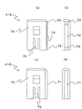
- the present invention is not limited to this. That is, as shown in FIGS. 21A and 21B, the first cutter blade receiving member 41 ⁇ / b> A having the first contact portion 72 and the recess 73 and the second cutter blade having the second contact portion 71. Both the receiving member 41 ⁇ / b> B may be prepared, and these may be selectively mounted on the holding portion 63 and used.
- the second cutter blade receiving member 41B is attached to the holding portion 63 (so that the second contact portion 71 faces the transport path side of the printed label tape 80), so that the printed label can be used.
- the entire tape 80 can be cut.
- the printed label tape is mounted by attaching the first cutter blade receiving member 41A to the holding portion 63 (so that the first contact portion 72 and the recessed portion 73 face the transport path side of the printed label tape 80).
- 80 half cuts can be made. That is, by exchanging the cutter blade receiving members 41A and 41B attached to the holding portion 76, both full cutting and desired cutting (half cutting in this example) are performed using the same one cutter blade 63. Can be executed. Thereby, compared with the conventional structure which needed to install both the cutting device for full cutting, and the cutting device for desired cutting, size reduction of a device and reduction of manufacturing cost can be aimed at.
- the cutter blade receiving member 41 ′ which is not attached to the holding portion 76 can be locked.
- a locking portion 76 ' may be provided at an appropriate location (see the imaginary line in FIG. 3).
- the locking portion 76 ′ in FIG. 3 is an example provided on the frame 13. In this way, by providing a storage place for the cutter blade receiving member 41 ′ that is not used by being mounted on the holding portion 76, the cutter blade receiving member 41 ′ is prevented from being lost and integrated with the main body of the print label producing apparatus 1. Has the effect of improving the ease of handling.
- the method is to print on the cover film 51 different from the base tape 53 and bond them together.
- the present invention is not limited to this, and the print-receiving tape layer provided in the base tape
- the present invention may be applied to a method for performing printing (a type in which bonding is not performed).
Landscapes
- Life Sciences & Earth Sciences (AREA)
- Forests & Forestry (AREA)
- Engineering & Computer Science (AREA)
- Mechanical Engineering (AREA)
- Handling Of Sheets (AREA)
- Nonmetal Cutting Devices (AREA)
Abstract
【課題】装置の大型化や製造コストの増大を招くことなく、被印字テープに対する全切断とそれ以外の態様の所望の切断との両方を実行する。 【解決手段】テープ搬送ローラ39及び押圧ローラ192、サーマルヘッド16、搬送経路と直交する方向Cに移動するカッタ刃63、保持部73を備えた印字ラベル作成装置本体と、カッタ刃63を受け止め可能なカッタ刃受け部材41とを有し、カッタ刃受け部材41は、印字済ラベル用テープ80のテープ全幅の少なくとも一部をテープ厚さ方向に受け入れ可能な凹部73、及び、カッタ刃63の刃先の接触を受け止める第1接触部72を備えた第1カッタ刃受け部41aと、印字済ラベル用テープ80のテープ全幅を挟みつつカッタ刃63の刃先の接触を受け止める第2接触部71を備えた第2カッタ刃受け部41bとを含む。
Description
本発明は、印字ラベルを作成する印字ラベル作成装置及びこれに用いる切断刃受け部材に関する。
被印字テープを搬送して所望の長さに切断し、印字ラベルを作成する印字ラベル作成装置が知られている(例えば、特許文献1参照)。この従来技術の印字ラベル作成装置では、印字手段により印字された被印字テープを、切断手段(カッタ)によって厚さ方向に全切断することにより、印字ラベルが作成される。また、この従来技術の印字ラベル作成装置では、上記全切断以外の所望の態様の切断(以下適宜「所望切断」という。この例では半切断)を行うために、被印字テープを厚さ方向に部分的に切断可能な半切断手段(ハーフカッタ)が設けられている。
上記従来技術では、通常の全切断を行うための手段(カッタ)と、所望切断を行うための手段(ハーフカッタ)との両方が別々に設けられており、装置の小型化が困難であり、また製造コストの増大を招くという課題があった
本発明の目的は、装置の大型化や製造コストの増大を招くことなく、被印字テープに対する全切断とそれ以外の態様の所望の切断との両方を実行できる印字ラベル作成装置、及びこれに用いる切断刃受け部材を提供することにある。
上記目的を達成するために、本願発明は、搬送経路に沿って所定の被印字テープを搬送する搬送手段、前記搬送手段により搬送される前記被印字テープに所望の印字を行う印字手段、前記搬送経路と直交する方向に移動して、印字された後の前記被印字テープを押し切るための切断刃、及び、前記切断刃による前記被印字テープの切断時に当該切断刃を受け止め可能な切断刃受け部材を着脱可能な保持部、を備えた印字ラベル作成装置本体と、少なくとも1つの前記切断刃受け部材と、を有する印字ラベル作成装置であって、前記少なくとも1つの切断刃受け部材は、前記被印字テープのテープ全幅の少なくとも一部をテープ厚さ方向に受け入れ可能な少なくとも1つの凹部、及び、前記凹部から前記テープ幅方向に沿った隣接位置に設けられ、当該隣接位置において前記切断刃の刃先の接触を受け止める第1接触部、を備えた、第1切断刃受け部材と、前記被印字テープのテープ全幅を挟みつつ前記切断刃の刃先の接触を受け止める第2接触部、を備えた、第2切断刃受け部材と、を含み、前記印字ラベル作成装置本体の前記保持部は、前記第1切断刃受け部材及び前記第2切断刃受け部材を選択的に装着可能に構成されていることを特徴とする。
本願発明の印字ラベル作成装置では、搬送手段により被印字テープが搬送され、その搬送される被印字テープに対し印字手段によって所望の印字が行われた後、切断刃を用いた被印字テープの切断が行われる。被印字テープの切断の際には、切断刃は、搬送経路と直交する方向に移動し、保持部に装着された切断刃受け部材によって受け止められる。
本願発明においては、保持部には、第1切断刃受け部材と第2切断刃受け部材との2種類が選択的に装着される。第2切断刃受け部材は第2接触部を備えており、この第2接触部は、上記切断刃の切断動作の際、被印字テープのテープ全幅を挟みつつ、切断刃の刃先の接触を受け止める。これにより、保持部に第2切断刃受け部材が装着された場合には、切断刃は被印字テープを厚さ方向に全切断することができる。
第1切断刃受け部材は、少なくとも1つの凹部と第1接触部とを備えている。凹部は、被印字テープのテープ全幅の少なくとも一部をテープ厚さ方向に受け入れる。第1接触部は、テープ幅方向に沿って凹部の隣接位置に設けられ、切断刃の刃先を受け止める。これにより、保持部に第1切断刃受け部材が装着された場合には、切断刃は、被印字テープのうち第1接触部に対応する部位を厚さ方向に全切断する。その一方、切断刃は、被印字テープのうち凹部に受け入れられた部位については、刃先が十分に届かなくなることから、厚さ方向に部分的に切断する(いわゆる半切断)か、若しくは、非切断とすることができる。
以上のようにして、本願発明においては、第2切断刃受け部材の装着時には通常の被印字テープの全切断を行うことができ、第1切断刃受け部材の装着時には被印字テープの少なくとも一部を半切断(又は非切断)とするような、意図する所望の態様の切断(所望切断)を行うことができる。すなわち、保持部に装着する切断刃受け部材を交換するだけで、同一の1つの切断刃を用いて全切断と所望切断との両方を実行することができる。これにより、全切断用の切断装置と所望切断用の切断装置との両方を設置する必要があった従来構造に比べ、装置の小型化及び製造コストの低減を図ることができる。
本発明によれば、装置の大型化や製造コストの増大を招くことなく、被印字テープに対する全切断とそれ以外の態様の所望の切断との両方を実行することができる。
以下、本発明の一実施の形態を図面を参照しつつ説明する。なお、以下の各図内に「前」「後」「左」「右」「上」「下」の注記がある場合は、明細書中内の説明における、前方、後方、左方、右方、上方、下方とは、その注記された方向を指す。
<装置の外観概略構造>
図1に示すように、印字ラベル作成装置1は、操作者の手によって把持されるハンディ型の印字ラベル作成装置である。この印字ラベル作成装置1の筐体6は、装置前面を構成する前カバー6Aと、装置後面を構成する後カバー6Bとで構成されている。さらにこの後カバー6Bは、種々の機構を内蔵する後カバー本体6B1と、カートリッジ31や乾電池8(いずれも後述の図2参照)を着脱する際に後カバー本体6B1より取り外し可能な着脱カバー6B2とで構成されている。
図1に示すように、印字ラベル作成装置1は、操作者の手によって把持されるハンディ型の印字ラベル作成装置である。この印字ラベル作成装置1の筐体6は、装置前面を構成する前カバー6Aと、装置後面を構成する後カバー6Bとで構成されている。さらにこの後カバー6Bは、種々の機構を内蔵する後カバー本体6B1と、カートリッジ31や乾電池8(いずれも後述の図2参照)を着脱する際に後カバー本体6B1より取り外し可能な着脱カバー6B2とで構成されている。
上記前カバー6Aの上側には、印刷データや、設定画面等を表示するための液晶表示部(図示せず)が設けられている。この液晶表示部の前面は、例えば透明のアクリル板等であるカバーパネル2Aによって覆われている。液晶表示部の下側には、印字ラベル作成装置1を操作するためのキーボード部3が設けられている。このキーボード部3には、文字、記号及び数字等の文字キーや、種々の機能キーが含まれている。また上記後カバー本体6B1の右側上端には、印刷済みラベル用テープ80(後述の図4参照)を切断するためのカットレバー4(操作レバー)が設けられている。
<装置の内部構造>
印字ラベル作成装置の内部構造を図2及び図3を用いて説明する。図2及び図3に示すように、上記前カバー6A及び上記後カバー本体6B1の内部には、樹脂(例えば合成樹脂など)により成形されたフレーム13が配設されている。そして、このフレーム13の後側上部には、カートリッジ31を着脱するために凹状に形成された平面視矩形状の上記カートリッジホルダ7が設けられている。
印字ラベル作成装置の内部構造を図2及び図3を用いて説明する。図2及び図3に示すように、上記前カバー6A及び上記後カバー本体6B1の内部には、樹脂(例えば合成樹脂など)により成形されたフレーム13が配設されている。そして、このフレーム13の後側上部には、カートリッジ31を着脱するために凹状に形成された平面視矩形状の上記カートリッジホルダ7が設けられている。
カートリッジホルダ7の下側には、モータ(図示せず)を収納するためのモータ収納部5が設けられている。モータ収納部5のさらに下側には、乾電池8を収納するための上記電池収納部9が設けられている。
上記フレーム13の上部には、印刷済みラベル用テープ80(後述の図4参照)を外部に排出するためのテープ排出スリット24が形成されている。また、フレーム13の右側上部には、ローラホルダ17(詳細構造は後述)が設けられている。ローラホルダ17の後側には、当該ローラホルダ17を覆うように設けられ、板状形状を有した合成樹脂製の板部25が設けられている。なお、この板部25はフレーム13と一体的に形成されている。さらに、この板部25の上部には、開口部である突起部挿入口10が設けられている。上記着脱カバー6B2が後カバー本体6B1に着脱されることにより、着脱カバー6B2に設けられた突起部45(後述の図5参照)が突起部挿入口10に挿抜される。
また、後カバー本体6B1の上端部にはロック穴11が設けられ、下端部にはロック穴12が2箇所設けられている。上記着脱カバー6B2が後カバー本体6B1に取り付けられた際に、着脱カバー6B2に設けられたロック部材47,48(後述の図5参照)がそれぞれロック穴11,12に嵌め込まれる。
上記フレーム13の略中央部には凹状に形成されたギア用凹部26が設けられている。ギア用凹部26には、ギア(図示せず)が設けられており、当該ギアの歯部は隠蔽用傘部114によって覆われ露出しない構造となっている。そして、ギアの後側には、インクリボン55(後述の図4参照)を巻き取るためのリボン巻取軸14が立設されている。上記ギア及びこれと噛合するフレーム13の前面側に設けられた複数のギア(図示せず)はそれぞれ合成樹脂で形成されており、またこれらのギアを回転可能に支持するギア軸(図示せず)も合成樹脂で形成されており、フレーム13と一体的に形成されている。
また、リボン巻取軸14の右側にはリブ30が立設されている。このリブ30の右側面には矩形状の放熱板であるヒートシンク15が設けられている。そして、リブ30とテープ排出スリット24との間には、ローラ軸20が立設されている。このローラ軸20は合成樹脂で形成されており、フレーム13と一体的に形成されている。ローラ軸20の左側には、凸部27が立設されている。この凸部27は、カートリッジ31の凹部(図示せず)に挿入されることで、カートリッジ31の前後方向の位置決めをするものである。
また、上記フレーム13のうち上記テープ排出スリット24の近傍には、カッタ刃63(後述の図11参照)を備えるカッタホルダ60(後述の図5参照)を内部に収容したガイドホルダ40が設けられている。さらに、上記フレーム13のうち上記テープ排出スリット24の近傍で、上記ガイドホルダ40の左側には、カッタ刃受け部材41が設けられている。このカッタ刃受け部材41は、カッタ刃63による印刷済みラベル用テープ80の切断時に、当該カッタ刃63を受け止めるためのものである。
また、上記カットレバー4は、(後述のレバー軸65を軸として)フレーム13に対し回動可能に支持されており、上記カッタ刃63を移動させることができる。
また、図3に示すように、上記テープ排出スリット24の近傍には、第1リブリブ42及び保持部76が、それぞれフレーム13と一体的に形成されている。テープ排出スリット24より右側に形成されたリブ42は、上記板部25の平面状の後面部25Aに対し垂直に立設されている。一方、テープ排出スリット24より左側に形成された保持部76は、上記カッタ刃受け部材41の左側に立設されており、当該カッタ刃受け部材41を保持する(取り付ける)ためのものである。
<カートリッジ内部構造>
カートリッジ31の内部構造を図4により説明する。図4に示すように、カートリッジケース33内の左側下部には、透明フィルム状のカバーフィルム51を巻回したカバーフィルムスプール52が回転可能に配置されている。このカバーフィルムスプール52から繰り出されたカバーフィルム51は、カートリッジ開口371に向けて案内され、当該カートリッジ開口371から送出される。またカートリッジケース33内の右側下部には、インクリボン55を巻回したリボンスプール56が回転可能に配置されている。このリボンスプール56から繰り出されたインクリボン55は、カートリッジ開口371に向けて案内され、カバーフィルム51と共に送出される。
カートリッジ31の内部構造を図4により説明する。図4に示すように、カートリッジケース33内の左側下部には、透明フィルム状のカバーフィルム51を巻回したカバーフィルムスプール52が回転可能に配置されている。このカバーフィルムスプール52から繰り出されたカバーフィルム51は、カートリッジ開口371に向けて案内され、当該カートリッジ開口371から送出される。またカートリッジケース33内の右側下部には、インクリボン55を巻回したリボンスプール56が回転可能に配置されている。このリボンスプール56から繰り出されたインクリボン55は、カートリッジ開口371に向けて案内され、カバーフィルム51と共に送出される。
カバーフィルムスプール52とリボンスプール56との間には、リボン巻取スプール57が回転可能に配置されている。このリボン巻取スプール57は、リボンスプール56からインクリボン55を引き出すと共に、文字等の印刷(印字)で消費されたインクリボン55を巻き取る。
カートリッジケース33内の上部には、基材テープ53を巻回した基材テープスプール54が回転可能に配置されている。基材テープ53はこの例では4層構造となっており(図4中部分拡大図参照)、径方向内側に巻かれる側(拡大図下側)よりその反対側(拡大図中上側)へ向かって、適宜の粘着剤からなる粘着層53a、PEL(ポリエチレンテレフタラート)等から成る色付きのベースフィルム(基材層)53b、適宜の粘着材からなる粘着層(粘着剤層)53c、剥離紙(剥離材層)53dの順序で積層され構成されている。この基材テープスプール54から繰り出された基材テープ53は、テープ搬送ローラ39に向けて案内され、当該基材テープ53と印刷済のカバーフィルム51とが、テープ搬送ローラ39と押圧ローラ192とによって上記粘着層53aを介し圧着されて印刷済みラベル用テープ80となり、ラベル用テープ排出口59に向けて搬送される。
また、カートリッジホルダ7に装着されたカートリッジ31の右側には、プラテンローラユニット18と押圧ローラユニット19とを備えたアーム状のローラホルダ17が、軸支部171を中心に左右方向に揺動可能に設けられている。このローラホルダ17も上記フレーム13と同様に合成樹脂製である。上記着脱カバー6B2が取り付けられると、突起部45(後述の図5参照)によりローラホルダ17がカートリッジ31方向に移動する。これにより、ローラホルダ17に設けられた押圧ローラユニット19とプラテンローラユニット18とが印刷位置(図4に示す位置)に移動する。
上記プラテンローラユニット18は、ヒートシンク15の右側に配置されている。プラテンローラユニット18には、プラテンローラ182とプラテンローラ用ギア(図示せず)とが設けられている。プラテンローラ182は、ヒートシンク15の右側面に設けられたサーマルヘッド16に対向する位置に配置されている。サーマルヘッド16は、押圧ローラ192、プラテンローラ182等により上記搬送経路に沿って搬送されるカバーフィルム51に対し、所望の印字を行うものである。プラテンローラ用ギアは、フレーム13の前側に設けられたギア(図示せず)に噛合されており、モータから動力を伝達されたプラテンローラ用ギアが回転することで、プラテンローラ182が回転する。これにより、プラテンローラユニット18が印刷位置に移動した際に、プラテンローラ182は、カバーフィルム51とインクリボン55とをサーマルヘッド16に対して押圧しつつ、文字、図形、記号等が印刷されたカバーフィルム51をその回転により押圧ローラユニット19の方向へ搬送する。
押圧ローラユニット19には、押圧ローラ192と押圧ローラ用ギア(図示せず)とが設けられている。押圧ローラ192は、上記ローラ軸20に対向する位置に配置されおり、カバーフィルム51、基材テープ53、及び印刷済みラベル用テープ80を、上記テープ排出スリット24へ向かう搬送経路(矢印ア,イ,ウ参照)に沿って搬送する。ローラ軸20は、円柱状に形成された円柱部201と、この円柱部201の外周から外側に向かって放射状に形成された6個のリブ202とから構成されている。また、ローラ軸20は、カートリッジ31に設けられたテープ搬送ローラ39の軸孔391に挿入され、テープ搬送ローラ39を回転可能に支持している。
押圧ローラ用ギアは、上記フレーム13の前側に設けられたギア(図示せず)に噛合されており、モータから動力を伝達された押圧ローラ用ギアが回転することで、押圧ローラ192が回転する。これにより、押圧ローラユニット19が印刷位置に移動した際に、押圧ローラ192は、カバーフィルム51と基材テープ53とを、ローラ軸20に回転可能に支持されたテープ搬送ローラ39に対して押圧する。これにより、印刷が行われたカバーフィルム51と基材テープ53とが圧着され印刷済みラベル用テープ80となり、上記ラベル用テープ排出口59より排出される。その後の印刷済みラベル用テープ80の搬送経路(言い換えれば、カバーフィルム51の搬送経路。以下同様)は、押圧ローラ192等により、上記ガイドホルダ40と上記カッタ刃受け部材41(図2等参照)との間を、下から上へ搬送されて上記テープ排出スリット24へ案内され、当該テープ排出スリット24から印字ラベル作成装置1の外部に排出される。その後、カッタ刃63により、印刷済みラベル用テープ80に対する切断(又は半切断。詳細は後述)が行われる。印刷済みラベル用テープ80の切断の際には、カッタ刃63は、搬送経路と直交する方向(後述の図11中C方向)に移動し、上記保持部76に装着されたカッタ刃受け部材41によって受け止められることにより、上記切断(又は半切断)を行う。
<着脱カバー>
着脱カバー6B2について図5により説明する。図5に示すように、着脱カバー6B2の前面6aの左側上端部には前述したロック部材47が立設され、下端部には前述した2つのロック部材48が立設されている。着脱カバー6B2が上記後カバー本体6B1に対し取り付けられた際に、これらロック部材47,48がそれぞれ上記後カバー本体6B1に設けられたロック穴11,12(図2等参照)に嵌め込まれる。これにより、着脱カバー6B2の自然開放が防止されるようになっている。
着脱カバー6B2について図5により説明する。図5に示すように、着脱カバー6B2の前面6aの左側上端部には前述したロック部材47が立設され、下端部には前述した2つのロック部材48が立設されている。着脱カバー6B2が上記後カバー本体6B1に対し取り付けられた際に、これらロック部材47,48がそれぞれ上記後カバー本体6B1に設けられたロック穴11,12(図2等参照)に嵌め込まれる。これにより、着脱カバー6B2の自然開放が防止されるようになっている。
そして、着脱カバー6B2が上記後カバー本体6B1(言い換えれば、フレーム13)に対し取り付けられることにより、前述した押圧ローラ192、サーマルヘッド16、カッタ刃63、及びカッタ刃受け部材41等からなる種々の機構を収納する機構収納空間(=着脱カバー6B2とフレーム13との間に生じる空間)を、フレーム13と協働して形成することができるようになっている。
また、着脱カバー6B2の前面6aの右側上部には、突起部45が、着脱カバー6B2の前面6aに対し垂直に立設されている。着脱カバー6B2が上記後カバー本体6B1に対し着脱されることにより、突起部45が上記後カバー本体6B1に設けられた突起部挿入口10(図2等参照)に挿抜される。これにより、上記ローラホルダ17を印刷位置(図4に示す位置)に移動させたり、待機位置(図3に示す位置)に移動させたりすることができるようになっている。また、突起部45は、着脱カバー6B2が上記後カバー本体6B1へ取り付けられた状態(言い換えれば、フレーム13に取り付けられた状態。以下同様)において、フレーム13と一体的に形成されたリブ42(図3参照)を、当該リブ42の右側から支持可能となっている。
また、着脱カバー6B2の前面6aの上部には、支持リブ46が、着脱カバー6B2の前面6aに対し垂直に立設されている。支持リブ46は、着脱カバー6B2が上記後カバー本体6B1へ取り付けられた状態において、フレーム13と一体的に形成された保持部76(図3参照)を、当該保持部76の左側から支持可能となっている。なお、保持部76において全切断時又は半切断時(後述)に印刷済みラベル用テープ80からの反力を十分に許容できる場合には、上記支持リブ46を省略してもよい。
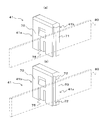
以上において、本実施形態の最大の特徴は、一方側と他方側とで形状の異なる、1つの共通のカッタ刃受け部材41を、向きを入れ替えつつ保持部76に装着することにより、印刷済みラベル用テープ80に対し、通常の全切断と半切断(後述)との両方をそれぞれ実行できることである。以下、その詳細を順を追って説明する。
<カッタ刃受け部材及び保持部の構造>
カッタ刃受け部材41と保持部76の詳細構造を、図6、図7、図8等を用いて説明する。
カッタ刃受け部材41と保持部76の詳細構造を、図6、図7、図8等を用いて説明する。
図6において、前述したように、テープ排出スリット24の左側において、この例では矩形板状の保持部76が(フレーム13と一体的に)立設されている。一方、カッタ刃受け部材41は、図7及び図8に示すように、この例では、角型袋状に形成されており、底部に形成されている挿入穴74を介し、保持部76(図6参照)に脱着自在に嵌着保持される。
このとき、保持部76の前後両面にかけて横長矩形状の係止孔76A(図6参照)が貫設されている。カッタ刃受け部材41は、この係止孔76Aに対応すべく、カッタ刃受け部材41の挿入穴74側において互いに相対峙するように突設された弾性フック片75(挿入穴74の前後下縁中央に各形成された凹み内側において垂下突出している)を備えている(図7(a)及び図7(b)参照)。これにより、例えば操作者が側面70を把持することでカッタ刃受け部材41を保持部76に嵌着する際には、当該カッタ刃受け部材41の挿入穴74側の前後一対の弾性フック片75が、保持部76の上記係止孔76Aに係合して保持される。また、例えば操作者が側面70を把持することで保持部76からカッタ刃受け部材41を強制的に引き上げることにより、弾性フック片75先端が壁面を乗り上げ、弾性フック片75は弾性的に拡開されることで、カッタ刃受け部材41が保持部76から離脱する。
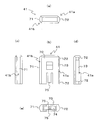
そして、本実施形態では、カッタ刃受け部材41は、一方側(図7(a)中左奥側、図7(b)中右手前側)に第1カッタ刃受け部41aを備え、他方側(図7(a)中右手前側、図7(b)中左奥側)に第2カッタ刃受け部41bを備えた、共通の1つのカッタ刃受け部材として構成されている。そして、カッタ刃受け部材41は、印刷済みラベル用テープ80の搬送経路に対して第1カッタ刃受け部41a側が向くように保持部76に装着する(図7(b)及び後述の図12参照)こともできるし、印刷済みラベル用テープ80の搬送経路に対して第2カッタ刃受け部41b側が向くように保持部76に装着する(図7(a)及び後述の図11(a)~(c)参照)こともできるように、なっている。
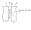
すなわち、図7(a)及び図8に示すように、第2カッタ刃受け部41bは、第2接触部71を備えている。この第2接触部71はこの例では樹脂で構成されており、図9に示すように、上記カッタ刃63の切断動作の際、印刷済みラベル用テープ80(カバーフィルム51、粘着層53a、ベースフィルム53b、粘着層53c、剥離紙53d)のテープ全幅を挟みつつ、カッタ刃63の刃先の接触を受け止める。これにより、カッタ刃63は印刷済みラベル用テープ80を厚さ方向に全切断することができる。
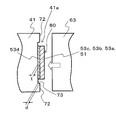
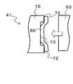
一方、図7(b)及び図8に示すように、第1カッタ刃受け部41aは、凹部73と、2つの第1接触部72とを備えている。このとき、図10に示すように、凹部73は、カバーフィルム51のテープ全幅をテープ厚さ方向に受け入れる。また、第1接触部72はこの例では金属で構成されており、テープ幅方向に沿って凹部73の両側隣接位置に設けられ、カッタ刃63の刃先をそれぞれ受け止める。これにより、カッタ刃63は、カバーフィルム51のうち凹部63に受け入れられた印刷済みラベル用テープ80の厚さ方向全寸法までは刃先が十分には届かなくなり、結果として厚さ方向に部分的に切断する(いわゆる半切断)こととなる(図10参照)。この例では、凹部73の深さ方向寸法dが上記剥離紙53dの厚さ方向寸法tと同等に予め定められている。この結果、カッタ刃63は、印刷済みラベル用テープ80のうち、剥離紙53dを残しつつ、その他の部分(カバーフィルム51、粘着層53a、ベースフィルム53b、粘着層53c)を切断することができる。
なお、凹部73の深さ方向寸法dの設定は上記に限られない。剥離紙53dの厚さ方向寸法tよりも小さくしてもよい。その場合、剥離紙53dについても厚さ方向寸法の一部を切断することができる。逆に、剥離紙53dの厚さ方向寸法tよりも大きくしてもよい。その場合、当該深さ方向寸法dの設定により、印字済ラベル用テープ80の残りの層、すなわち、カバーフィルム51、粘着層53a、ベースフィルム53b、粘着層53cのうちどの層までを切断し、どの層を残す(未切断とする)かを、適宜所望の態様に設定することができる。
<テープ全切断動作>
次に、カッタ刃63の印刷済みラベル用テープ80に対する全切断動作を、図11(a)~(c)により説明する。なお、これら図11(a)~(c)は、印字ラベル作成装置1から着脱カバー6B2を取り外した状態において、テープ排出スリット24近傍における、カッタボタン4、ガイドホルダ40、及びカッタ刃受け部材41を後面側から透視した図に相当している。
次に、カッタ刃63の印刷済みラベル用テープ80に対する全切断動作を、図11(a)~(c)により説明する。なお、これら図11(a)~(c)は、印字ラベル作成装置1から着脱カバー6B2を取り外した状態において、テープ排出スリット24近傍における、カッタボタン4、ガイドホルダ40、及びカッタ刃受け部材41を後面側から透視した図に相当している。
図11(a)、図11(b)、図11(c)において、全切断を行う場合は、前述したように、操作者は、第2カッタ刃受け部41bが印字済ラベル用テープ80の搬送経路側となるように、保持部76に対しカッタ刃受け部材41を装着する。このとき、図示のように、カットレバー4は、上記フレーム13に形成されたレバー軸65を軸として、フレーム13に対し回動可能に支持されている。前述のようにして、ラベル用テープ排出口59(図4参照)より排出された印刷済みラベル用テープ80は、押圧ローラ192(図4参照)等により、上記搬送経路に沿って、ガイドホルダ40とカッタ刃受け部材41との間を下から上へ搬送される。そして、テープ排出スリット24へ案内され、当該テープ排出スリット24から印字ラベル作成装置1の外部に(その一部が)排出され、図11(a)に示す状態になる。
そして、図11(a)に示すように、操作者によってカットレバー4の回動操作がまだ行われていない初期状態においては、カットレバー4は、初期位置(図11(a)に示す位置)に位置する。この初期位置に位置する場合、カットレバー4の接触部4Aは、上記接触凸部62から離間している。
このとき、操作者によってカットレバー4の回動操作が行われると、当該カットレバー4は、レバー軸65を軸として、レバー回転方向Rへ回動する。そして、カットレバー4が所定量回動すると、カットレバー4の接触部4Aは、上記接触凸部62に接触する。その後、操作者の操作に伴いカットレバー4がレバー回転方向Rへさらに回動すると、上記接触部4Aは、接触している接触凸部62を介して、カッタホルダ60を、印刷済みラベル用テープ80の搬送経路と直交する矢印Cの方向(左方向)へ移動させる。またこのとき、カッタホルダ60の矢印Cの方向への移動に伴い、カッタ刃63も矢印Cの方向に移動する。なお、この矢印Cの方向が、各請求項記載の「搬送経路と直交する方向」に対応している。
そして、カットレバー4がレバー回転方向Rへさらに回動され、上記接触部4A及び接触凸部62を介して、カッタホルダ60が、矢印Cの方向へ所定量移動すると、カッタ刃63の先端は、印刷済みラベル用テープ80と接触する(図11(b)に示す状態)。その後、カットレバー4がレバー回転方向Rへさらに回動されると、上記接触部4A及び接触凸部62を介して、カッタホルダ60が、矢印Cの方向へさらに移動する。これに伴い、カッタ刃63は、印刷済みラベル用テープ80に接触した状態から、カッタ刃63とカッタ刃受け部材41との間に生じる押圧力(=カットレバー4の回動操作に基づく力)により、徐々にカッタ刃63が印刷済みラベル用テープ80を押し切りつつ、最終的にカッタ刃受け部材41に接触する(図11(c)に示す状態)。これにより、カッタ刃63は、カットレバー4の回動操作に基づくカッタ刃63とカッタ刃受け部材41との間に生じる押圧力により、印刷済みラベル用テープ80を厚さ方向全寸法にわたって完全に押し切ることができる(図9参照)。
<半切断動作>
次に、カッタ刃63による半切断動作を図12により説明する。図12に示すように、半切断を行う場合は、前述したように、操作者は、第1カッタ刃受け部41aが印字済ラベル用テープ80の搬送経路側となるように(上記図11(a)~(c)とは逆向きに)、保持部76に対しカッタ刃受け部材41を装着する。操作者が上記図11(a)~(c)を用いて説明したのと同様にカットレバー4をレバー回転方向Rへ回動することにより、カッタホルダ60が矢印Cの方向へ上記同様の挙動で移動する。その際、前述の第1カッタ刃受け部41aの凹部73の構造により、当該凹部73に受け入れられて入り込んだ印字済ラベル用テープ80は、カッタ刃63からみて進行方向前方側にずれた形で配置されている。この結果、カッタ刃63の先端は、上記図11(a)~(c)の全切断時よりも遅れたタイミングで(言い換えれば全切断時よりも多いカットレバー4の操作量で)印刷済みラベル用テープ80と接触し、徐々にカッタ刃63が印刷済みラベル用テープ80の押し切りを進行させる。そして、最終的にはカッタ刃63が第1カッタ刃受け部41aの第1接触部72に当接する。これにより、カッタ刃63は、カッタ刃63とカッタ刃受け部材41との間に生じる押圧力により、印刷済みラベル用テープ80のうち剥離紙53を除く部分、すなわち、カバーフィルム51、粘着層53a、ベースフィルム53b、粘着層53cについて、厚さ方向全寸法にわたって押し切る(図10参照)。
次に、カッタ刃63による半切断動作を図12により説明する。図12に示すように、半切断を行う場合は、前述したように、操作者は、第1カッタ刃受け部41aが印字済ラベル用テープ80の搬送経路側となるように(上記図11(a)~(c)とは逆向きに)、保持部76に対しカッタ刃受け部材41を装着する。操作者が上記図11(a)~(c)を用いて説明したのと同様にカットレバー4をレバー回転方向Rへ回動することにより、カッタホルダ60が矢印Cの方向へ上記同様の挙動で移動する。その際、前述の第1カッタ刃受け部41aの凹部73の構造により、当該凹部73に受け入れられて入り込んだ印字済ラベル用テープ80は、カッタ刃63からみて進行方向前方側にずれた形で配置されている。この結果、カッタ刃63の先端は、上記図11(a)~(c)の全切断時よりも遅れたタイミングで(言い換えれば全切断時よりも多いカットレバー4の操作量で)印刷済みラベル用テープ80と接触し、徐々にカッタ刃63が印刷済みラベル用テープ80の押し切りを進行させる。そして、最終的にはカッタ刃63が第1カッタ刃受け部41aの第1接触部72に当接する。これにより、カッタ刃63は、カッタ刃63とカッタ刃受け部材41との間に生じる押圧力により、印刷済みラベル用テープ80のうち剥離紙53を除く部分、すなわち、カバーフィルム51、粘着層53a、ベースフィルム53b、粘着層53cについて、厚さ方向全寸法にわたって押し切る(図10参照)。
なお、上述の保持部76への係止構造により、上記カッタ刃63による印刷済みラベル用テープ80の全切断及び半切断に際し、カッタ刃受け部材41は、切断動作のどの時点においても、一定の位置から動くことはほとんどない。
<印字ラベル>
以上のようにして、操作者がカッタ刃受け部材41の向きを付け替えつつ作成した印字ラベルLの一例を、図13及び図14を用いて説明する。
以上のようにして、操作者がカッタ刃受け部材41の向きを付け替えつつ作成した印字ラベルLの一例を、図13及び図14を用いて説明する。
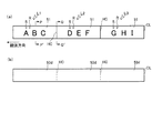
そして、図13(a)及び図13(b)において、この例では、3つの印字ラベルL1,L2,L2からなる印字ラベル連続体が作成されている。これら印字ラベルL1,L2,L3は、上述のようにして印字済ラベル用テープ80の切断又は半切断が完了して形成されたものであり、前述の図4に示した4層構造にカバーフィルム51が加わった5層構造となっている(図14(a)参照)。すなわち、カバーフィルム51側(図14(a)中上側)よりその反対側(図14(a)中下側)へ向かって、カバーフィルム51、粘着層53a、ベースフィルム53b、粘着層53c、剥離紙53dで5層を構成している。そして、カバーフィルム51の裏面にそれぞれ印字Rが印刷されている。
この例では、印字ラベル連続体が作成されたとき、第1カッタ刃受け部41aが印字済ラベル用テープ80の搬送経路側となるようにカッタ刃受け部材41が装着され、カッタ刃63が半切断を行う状態として、「ABC」の印字Rを備えた印字ラベルL1と、「DEF」の印字Rを備えた印字ラベルL2とが作成されている。これによって印字ラベルL1の搬送方向上流側(図示右側)の後端部(言い換えれば印字ラベルL2との境界部)は、上記半切断の結果である、印刷済みラベル用テープ80のうち剥離紙53を除く部分、すなわち、カバーフィルム51、粘着層53a、ベースフィルム53b、粘着層53cが分断されたハーフカット部HCとなっている(図14(b)参照)。また印字ラベルL2の搬送方向上流側の後端部(言い換えれば印字ラベルL3との境界部)についても同様である。
そして、上記の後、第2カッタ刃受け部41bが印字済ラベル用テープ80の搬送経路側となるようにカッタ刃受け部材41が付け替えられ、カッタ刃63が半切断を行う状態として、「GHI」の印字Rを備えた印字ラベルL3が作成されている。これによって、印字ラベルL3の搬送方向上流側の後端部(言い換えれば印字ラベル連続体の後端部)は、上記全切断の結果である、印刷済みラベル用テープ80のうちすべての層が分断されたフルカット線CLとなっている。
以上説明したように、本実施形態の印字ラベル作成装置1においては、印刷済みラベル用テープ80が、カッタ刃63とカッタ刃受け部材41との協働により、所定の長さに切断されることで、所望の印字Rを備えた印字ラベルLが作成される。
その際、保持部63に対しカッタ刃受け部材41が着脱自在に構成されている。第2カッタ刃受け部41bを印字済ラベル用テープ80の搬送経路側に向けるようにカッタ刃受け部材41を保持部63に装着することで、印字済ラベル用テープ80の全切断を行うことができる。第1カッタ刃受け部41aを印字済ラベル用テープ80の搬送経路側に向けるようにカッタ刃受け部材41を保持部63に装着することで、印字済ラベル用テープ80の半切断を行うことができる。すなわち、保持部76に装着するカッタ刃受け部材41を逆向きに付け替えるだけで、同一の1つのカッタ刃63を用いて全切断と所望の態様の切断(この例では半切断)との両方を実行することができる。これにより、全切断用の切断装置と所望切断用の切断装置との両方を設置する必要があった従来構造に比べ、装置の小型化及び製造コストの低減を図ることができる。
また、本実施形態では特に、共通の1つのカッタ刃受け部材41の向きを付け替えるだけで切断態様を切り替えることができるので、第1カッタ刃受け部41aに相当するカッタ刃受け部材と第2カッタ刃受け部41bに相当するカッタ刃受け部材との2つを別々に用意する場合(後述の変形例(4)参照)よりも、部品点数を少なくできるとともに、取り扱い性も向上することができる。
また、本実施形態では、特に第1カッタ刃受け部41aの第1接触部72が、金属で構成されているので、樹脂等で構成した場合に生じうる第1接触部72の摩耗を回避することができる。但しこの場合、第1接触部72による上記の刃先の受け止めによって、カッタ刃63の刃先のうち、上記第1接触部72により受け止められる部分の摩耗が生じる。しかしながら、上記のように、第1接触部72は印字済ラベル用テープ80の全幅を受け入れる凹部73よりもテープ幅方向の両側に設けられていることから、カッタ刃63の刃先のうち上記摩耗が生じる部分は、印字済ラベル用テープ80の厚さ方向への全切断に寄与しない部分である。したがって、摩耗したとしても、カッタ刃63の切断性能には何ら問題はない。また、第2接触部71は樹脂で構成されているので、上記全切断時にカッタ刃63の刃先を傷めることが少ない。以上の結果、カッタ刃63の切断性能を確保しつつ、第1切断刃受け部材の摩耗を回避することができる。
なお、本発明は、上記実施形態に限られるものではなく、その技術思想を逸脱しない範囲内で種々の変形が可能である。以下、そのような変形例を説明する。
(1)テープ幅方向両端を残し中央側のみ切断する、所望切断を行う場合
本変形例においては、図15に示すように、第1カッタ刃受け部41aは、中央の1つの第1接触部72と、この第1接触部72のテープ幅方向両側にそれぞれ隣接するテープ幅方向両側の2つの凹部73とを備えている。凹部73は、印字済ラベル用テープ80のテープ全幅の一部(この例ではテープ幅方向両端部分)をテープ厚さ方向に受け入れる。また、凹部73の深さ方向寸法は、この例では、印字済ラベル用テープ80の厚さ方向寸法と同等(あるいはそれよりも深く)なっている。この結果、第1カッタ刃受け部41aを印字済ラベル用テープ80の搬送経路側に向けて保持部76に設置した場合、カッタ刃63の刃先が印字済ラベル用テープ80のうち凹部73内に位置する部分に届かず、非切断となる(図16参照)。その一方、第1接触部72は、上記同様、カッタ刃63の刃先を受け止めることにより、カッタ刃63は、印字済ラベル用テープ80のうち第1接触部72に対応する部位については厚さ方向に全切断する。
本変形例においては、図15に示すように、第1カッタ刃受け部41aは、中央の1つの第1接触部72と、この第1接触部72のテープ幅方向両側にそれぞれ隣接するテープ幅方向両側の2つの凹部73とを備えている。凹部73は、印字済ラベル用テープ80のテープ全幅の一部(この例ではテープ幅方向両端部分)をテープ厚さ方向に受け入れる。また、凹部73の深さ方向寸法は、この例では、印字済ラベル用テープ80の厚さ方向寸法と同等(あるいはそれよりも深く)なっている。この結果、第1カッタ刃受け部41aを印字済ラベル用テープ80の搬送経路側に向けて保持部76に設置した場合、カッタ刃63の刃先が印字済ラベル用テープ80のうち凹部73内に位置する部分に届かず、非切断となる(図16参照)。その一方、第1接触部72は、上記同様、カッタ刃63の刃先を受け止めることにより、カッタ刃63は、印字済ラベル用テープ80のうち第1接触部72に対応する部位については厚さ方向に全切断する。
この例では、印字ラベル連続体が作成されたとき、第1カッタ刃受け部41aが印字済ラベル用テープ80の搬送経路側となるようにカッタ刃受け部材41が装着され、カッタ刃63が上記所望切断を行う状態として、「ABC」の印字Rを備えた印字ラベルL1と、「DEF」の印字Rを備えた印字ラベルL2とが作成されている。これによって印字ラベルL1の搬送方向上流側(図示右側)の後端部(言い換えれば印字ラベルL2との境界部)は、上記所望切断の結果、テープ幅方向両端を残し中央側のみスリット状のフルカット部FCが形成される。また印字ラベルL2の搬送方向上流側の後端部(言い換えれば印字ラベルL3との境界部)についても同様である。
そして、上記の後、第2カッタ刃受け部41bが印字済ラベル用テープ80の搬送経路側となるようにカッタ刃受け部材41が付け替えられ、カッタ刃63が半切断を行う状態として、「GHI」の印字Rを備えた印字ラベルL3が作成されている。これによって、印字ラベルL3の搬送方向上流側の後端部(言い換えれば印字ラベル連続体の後端部)は、上記全切断の結果である、印刷済みラベル用テープ80のうちすべての層が分断されたフルカット線CLとなっている。
本変形例においても、上記実施形態と同様の効果を得る。すなわち、第2カッタ刃受け部41bを印字済ラベル用テープ80の搬送経路側に向けるようにカッタ刃受け部材41を保持部63に装着することで、印字済ラベル用テープ80の全切断を行うことができる。また、第1カッタ刃受け部41aを印字済ラベル用テープ80の搬送経路側に向けるようにカッタ刃受け部材41を保持部63に装着することで、印字済ラベル用テープ80に対する上記所望切断を行うことができる。すなわち、保持部76に装着するカッタ刃受け部材41を逆向きに付け替えるだけで、同一の1つのカッタ刃63を用いて全切断と所望切断(この例ではテープ幅方向両端を残し中央側のみ切断)との両方を実行することができる。
(2)テープ幅方向中央側を残し両端のみ切断する所望切断を行う場合
本変形例においては、図17に示すように、第1カッタ刃受け部41aは、中央の1つの凹部73と、この凹部73のテープ幅方向両側にそれぞれ隣接するテープ幅方向両側の2つの第1接触部72とを備えている。凹部73は、印字済ラベル用テープ80のテープ全幅の一部(この例ではテープ幅方向中央部)をテープ厚さ方向に受け入れる。また、凹部73の深さ方向寸法は、この例でも、上記同様、印字済ラベル用テープ80の厚さ方向寸法と同等(あるいはそれよりも深く)なっている。この結果、第1カッタ刃受け部41aを印字済ラベル用テープ80の搬送経路側に向けて保持部76に設置した場合、カッタ刃63の刃先が印字済ラベル用テープ80のうち凹部73内に位置する部分に届かず、非切断となる(図18参照)。その一方、第1接触部72は、上記同様、カッタ刃63の刃先を受け止めることにより、カッタ刃63は、印字済ラベル用テープ80のうち第1接触部72に対応する部位(テープ幅方向両端部)については厚さ方向に全切断する。
本変形例においては、図17に示すように、第1カッタ刃受け部41aは、中央の1つの凹部73と、この凹部73のテープ幅方向両側にそれぞれ隣接するテープ幅方向両側の2つの第1接触部72とを備えている。凹部73は、印字済ラベル用テープ80のテープ全幅の一部(この例ではテープ幅方向中央部)をテープ厚さ方向に受け入れる。また、凹部73の深さ方向寸法は、この例でも、上記同様、印字済ラベル用テープ80の厚さ方向寸法と同等(あるいはそれよりも深く)なっている。この結果、第1カッタ刃受け部41aを印字済ラベル用テープ80の搬送経路側に向けて保持部76に設置した場合、カッタ刃63の刃先が印字済ラベル用テープ80のうち凹部73内に位置する部分に届かず、非切断となる(図18参照)。その一方、第1接触部72は、上記同様、カッタ刃63の刃先を受け止めることにより、カッタ刃63は、印字済ラベル用テープ80のうち第1接触部72に対応する部位(テープ幅方向両端部)については厚さ方向に全切断する。
この例でも、上記同様、第1カッタ刃受け部41aが印字済ラベル用テープ80の搬送経路側となるようにカッタ刃受け部材41が装着され、「ABC」の印字R「DEF」の印字Rをそれぞれ備えた印字ラベルL1,L2が作成されている。これによって印字ラベルL1の搬送方向上流側(図示右側)の後端部(印字ラベルL2との境界部)は、上記所望切断の結果、テープ幅方向中央側を残し両端部のみスリット状のフルカット部FCが形成される。また印字ラベルL2の搬送方向上流側の後端部(言い換えれば印字ラベルL3との境界部)についても同様である。
その後、「GHI」の印字Rを備えた印字ラベルL3の作成については、上記同様であり、説明を省略する。
本変形例においても、上記同様、第1カッタ刃受け部41aを搬送経路側に向けるようにカッタ刃受け部材41を装着することで、印字済ラベル用テープ80に対する上記所望切断を行うことができる。したがって、同一の1つのカッタ刃63を用いて全切断と所望切断(この例ではテープ幅方向中央側を残し両端部のみ切断)との両方を実行することができる。
(3)テープ幅方向片側端部を残し、残り全部を切断する所望切断を行う場合
本変形例においては、図19に示すように、第1カッタ刃受け部41aは、テープ幅方向に沿った一方側端部に対応する1つの凹部73と、この凹部73のテープ幅方向に沿った他方側に隣接する1つの第1接触部72とを備えている。凹部73は、印字済ラベル用テープ80のテープ全幅の一部(この例ではテープ幅方向一方側端部)をテープ厚さ方向に受け入れる。また、凹部73の深さ方向寸法は、この例でも、上記同様、印字済ラベル用テープ80の厚さ方向寸法と同等(あるいはそれよりも深く)なっている。この結果、第1カッタ刃受け部41aを印字済ラベル用テープ80の搬送経路側に向けて保持部76に設置した場合、カッタ刃63の刃先が印字済ラベル用テープ80のうち凹部73内に位置する部分に届かず、非切断となる(図20参照)。その一方、第1接触部72は、上記同様、カッタ刃63の刃先を受け止めることにより、カッタ刃63は、印字済ラベル用テープ80のうち第1接触部72に対応する部位(テープ幅方向一方側端部以外の部位)については厚さ方向に全切断する。
本変形例においては、図19に示すように、第1カッタ刃受け部41aは、テープ幅方向に沿った一方側端部に対応する1つの凹部73と、この凹部73のテープ幅方向に沿った他方側に隣接する1つの第1接触部72とを備えている。凹部73は、印字済ラベル用テープ80のテープ全幅の一部(この例ではテープ幅方向一方側端部)をテープ厚さ方向に受け入れる。また、凹部73の深さ方向寸法は、この例でも、上記同様、印字済ラベル用テープ80の厚さ方向寸法と同等(あるいはそれよりも深く)なっている。この結果、第1カッタ刃受け部41aを印字済ラベル用テープ80の搬送経路側に向けて保持部76に設置した場合、カッタ刃63の刃先が印字済ラベル用テープ80のうち凹部73内に位置する部分に届かず、非切断となる(図20参照)。その一方、第1接触部72は、上記同様、カッタ刃63の刃先を受け止めることにより、カッタ刃63は、印字済ラベル用テープ80のうち第1接触部72に対応する部位(テープ幅方向一方側端部以外の部位)については厚さ方向に全切断する。
この例でも、上記同様、第1カッタ刃受け部41aが印字済ラベル用テープ80の搬送経路側となるようにカッタ刃受け部材41が装着され、「ABC」の印字R「DEF」の印字Rをそれぞれ備えた印字ラベルL1,L2が作成されている。これによって印字ラベルL1の搬送方向上流側(図示右側)の後端部(印字ラベルL2との境界部)は、上記所望切断の結果、テープ幅方向片側端部を残し残り全部にスリット状のフルカット部FCが形成される。また印字ラベルL2の搬送方向上流側の後端部(言い換えれば印字ラベルL3との境界部)についても同様である。
その後、「GHI」の印字Rを備えた印字ラベルL3の作成については、上記同様であり、説明を省略する。
本変形例においても、上記同様、第1カッタ刃受け部41aを搬送経路側に向けるようにカッタ刃受け部材41を装着することで、印字済ラベル用テープ80に対する上記所望切断を行うことができる。したがって、同一の1つのカッタ刃63を用いて全切断と所望切断(この例ではテープ幅方向片側端部を残し残り全部を切断)との両方を実行することができる。
(4)2種類のカッタ刃受け部材を用意して交換して使用する場合
すなわち、以上においては、1つの共通のカッタ刃受け部材41が、所望切断用の第1カッタ刃受け部41aと全切断用の第2カッタ刃受け部41bとを備えていたが、これに限られない。すなわち、図21(a)及び図21(b)に示すように、第1接触部72及び凹部73を備えた第1カッタ刃受け部材41Aと、第2接触部71を備えた第2カッタ刃受け部材41Bと、の両方を用意して、これらを選択的に保持部63に装着して用いるようにしてもよい。
すなわち、以上においては、1つの共通のカッタ刃受け部材41が、所望切断用の第1カッタ刃受け部41aと全切断用の第2カッタ刃受け部41bとを備えていたが、これに限られない。すなわち、図21(a)及び図21(b)に示すように、第1接触部72及び凹部73を備えた第1カッタ刃受け部材41Aと、第2接触部71を備えた第2カッタ刃受け部材41Bと、の両方を用意して、これらを選択的に保持部63に装着して用いるようにしてもよい。
本変形例においては、第2カッタ刃受け部材41Bを、(第2接触部71が印字済ラベル用テープ80の搬送経路側に向くように)保持部63に装着することで、印字済ラベル用テープ80の全切断を行うことができる。また、第1カッタ刃受け部材41Aを、(第1接触部72及び凹部73が印字済ラベル用テープ80の搬送経路側に向くように)保持部63に装着することで、印字済ラベル用テープ80の半切断を行うことができる。すなわち、保持部76に装着するカッタ刃受け部材41A,41Bを交換することで、同一の1つのカッタ刃63を用いて全切断と所望の態様の切断(この例では半切断)との両方を実行することができる。これにより、全切断用の切断装置と所望切断用の切断装置との両方を設置する必要があった従来構造に比べ、装置の小型化及び製造コストの低減を図ることができる。
なお、本変形例において、例えば、第1カッタ刃受け部材と第2カッタ刃受け部材との2種類のうち、保持部76に装着されていないほうのカッタ刃受け部材41′を係止可能とする係止部76′を適宜の箇所に設けてもよい(図3の想像線参照)。図3の係止部76′は、フレーム13に設けた例である。このように保持部76に装着して使用しないカッタ刃受け部材41′の収納場所を設けることにより、当該カッタ刃受け部材41′の紛失を防止し、また印字ラベル作成装置1本体との一体的な取り扱い性を向上できる効果がある。
(5)その他
以上においては、基材テープ53とは別のカバーフィルム51に印字を行ってこれらを貼り合わせる方式であったが、これに限られず、基材テープに備えられた被印字テープ層に印字を行う方式(貼りあわせを行わないタイプ)に本発明を適用してもよい。
以上においては、基材テープ53とは別のカバーフィルム51に印字を行ってこれらを貼り合わせる方式であったが、これに限られず、基材テープに備えられた被印字テープ層に印字を行う方式(貼りあわせを行わないタイプ)に本発明を適用してもよい。
また、以上既に述べた以外にも、上記実施形態や各変形例による手法を適宜組み合わせて利用しても良い。
その他、一々例示はしないが、本発明は、その趣旨を逸脱しない範囲内において、種々の変更が加えられて実施されるものである。
1 印字ラベル作成装置
16 サーマルヘッド
41 カッタ刃受け部材
41A カッタ刃受け部材
41a 第1カッタ刃受け部
41B カッタ刃受け部材
41b 第2カッタ刃受け部
51 カバーフィルム
63 カッタ刃
76 保持部
71 第2接触部
72 第1接触部
73 凹部
80 印字済ラベル用テープ
162 プラテンローラ
192 押圧ローラ
16 サーマルヘッド
41 カッタ刃受け部材
41A カッタ刃受け部材
41a 第1カッタ刃受け部
41B カッタ刃受け部材
41b 第2カッタ刃受け部
51 カバーフィルム
63 カッタ刃
76 保持部
71 第2接触部
72 第1接触部
73 凹部
80 印字済ラベル用テープ
162 プラテンローラ
192 押圧ローラ
Claims (14)
- 搬送経路に沿って所定の被印字テープ(51;80)を搬送する搬送手段(192,182)、
前記搬送手段(192,182)により搬送される前記被印字テープ(51;80)に所望の印字を行う印字手段(16)、
前記搬送経路と直交する方向に移動して、印字された後の前記被印字テープ(51;80)を押し切るための切断刃(63)、及び、
前記切断刃(63)による前記被印字テープ(51;80)の切断時に当該切断刃(63)を受け止め可能な切断刃受け部材(41;41A,41B;41′)を着脱可能な保持部(76)、
を備えた印字ラベル作成装置本体と、
少なくとも1つの前記切断刃受け部材(41;41A,41B;41′)と、
を有する印字ラベル作成装置であって、
前記少なくとも1つの切断刃受け部材(41;41A,41B;41′)は、
前記被印字テープ(51;80)のテープ全幅の少なくとも一部をテープ厚さ方向に受け入れ可能な少なくとも1つの凹部(73)、及び、前記凹部(73)から前記テープ幅方向に沿った隣接位置に設けられ、当該隣接位置において前記切断刃(63)の刃先の接触を受け止める第1接触部(72)、を備えた、第1切断刃受け部材(41a;41A)と、
前記被印字テープ(51;80)のテープ全幅を挟みつつ前記切断刃(63)の刃先の接触を受け止める第2接触部(71)、を備えた、第2切断刃受け部材(41b;41B)と、
を含み、
前記印字ラベル作成装置本体の前記保持部(76)は、
前記第1切断刃受け部材(41a;41A)及び前記第2切断刃受け部材(41b;41B)を選択的に装着可能に構成されている
ことを特徴とする印字ラベル作成装置(1)。 - 請求項1記載の印字ラベル作成装置において、
前記第1切断刃受け部材(41a;41A)は、
前記テープ幅方向に沿った中央側に設けられ、前記被印字テープ(51;80)のテープ全幅をテープ厚さ方向に受け入れ可能な1つの前記凹部(73)、及び、前記凹部(73)の前記テープ幅方向に沿った両側に隣接して設けられ、前記切断刃(63)の刃先の接触を受け止める前記第1接触部(72)、を備えており、
前記印字ラベル作成装置本体の前記切断刃(63)は、
前記保持部(76)に前記第2切断刃受け部材(41b;41B)が装着された場合には、前記被印字テープ(51;80)を厚さ方向に全切断し、
前記保持部(76)に前記第1切断刃受け部材(41a;41A)が装着された場合には、前記被印字テープ(51;80)を厚さ方向に部分的に切断する
ことを特徴とする印字ラベル作成装置(1)。 - 請求項1記載の印字ラベル作成装置において、
前記第1切断刃受け部材(41a)は、
前記テープ幅方向に沿った両端部に設けられ、前記被印字テープ(51;80)のテープ幅方向両端部をテープ厚さ方向にそれぞれ受け入れ可能な2つの前記凹部(73,73)、及び、前記2つの凹部(73,73)の前記テープ幅方向に沿った中間部に設けられ、前記切断刃(63)の刃先の接触を受け止める1つの前記第1接触部(72)、を備えており、
前記印字ラベル作成装置本体の前記切断刃(63)は、
前記保持部(76)に前記第1切断刃受け部材(41a)が装着された場合には、前記被印字テープ(51;80)の幅方向両端部を厚さ方向に部分的に切断するとともに、前記幅方向両端部の間の中間部を厚さ方向に全切断する
ことを特徴とする印字ラベル作成装置(1)。 - 請求項1記載の印字ラベル作成装置において、
前記第1切断刃受け部材(41a)は、
前記テープ幅方向に沿った中間部に設けられ、前記被印字テープ(51;80)のテープ幅方向中間部をテープ厚さ方向に受け入れ可能な1つの前記凹部(73)、及び、前記1つの凹部(73)の前記テープ幅方向両側に隣接した前記被印字テープ(51;80)のテープ幅方向両端部に設けられ、前記切断刃(63)の刃先の接触をそれぞれ受け止める2つの前記第1接触部(72,72)、を備えており、
前記印字ラベル作成装置本体の前記切断刃(63)は、
前記保持部(76)に前記第1切断刃受け部材(41a)が装着された場合には、前記被印字テープ(51;80)の幅方向両端部を厚さ方向に全切断するとともに、前記幅方向両端部の間の中間部を厚さ方向に部分的に切断する
ことを特徴とする印字ラベル作成装置(1)。 - 請求項1記載の印字ラベル作成装置において、
前記第1切断刃受け部材(41a)は、
前記テープ幅方向に沿った一方側端部に設けられ、前記被印字テープ(51;80)のテープ幅方向一方側端部をテープ厚さ方向に受け入れ可能な1つの前記凹部(73)、及び、前記1つの凹部(73)の前記テープ幅方向に沿った他方側に隣接して、前記被印字テープ(51;80)のテープ幅方向他方側端部まで延びるように設けられ、前記切断刃(63)の刃先の接触を受け止める1つの前記第1接触部(72)、を備えており、
前記印字ラベル作成装置本体の前記切断刃(63)は、
前記保持部(76)に前記第1切断刃受け部材(41a)が装着された場合には、前記被印字テープ(51;80)の前記幅方向一方側端部を厚さ方向に部分的に切断するとともに、当該幅方向一方側端部以外の部分を厚さ方向に全切断する
ことを特徴とする印字ラベル作成装置(1)。 - 請求項2乃至請求項5のいずれか1項記載の印字ラベル作成装置において、
前記印字ラベル作成装置本体の前記第1切断刃受け部材(41a)の前記第1接触部(72)は、金属で構成されており、
前記第2切断刃受け部材(41b)の前記第2接触部(71)は、樹脂で構成されている
ことを特徴とする印字ラベル作成装置(1)。 - 請求項1乃至請求項6のいずれか1項記載の印字ラベル作成装置において、
前記第1切断刃受け部材(41a)及び前記第2切断刃受け部材(41b)は、一方側に当該第1切断刃受け部材(41a)を備え他方側に当該第2切断刃受け部材(41b)を備えた、共通の1つの切断刃受け部材(41)として構成されている
ことを特徴とする印字ラベル作成装置(1)。 - 請求項1乃至請求項6のいずれか1項記載の印字ラベル作成装置において、
前記第1切断刃受け部材及び前記第2切断刃受け部材のうち、前記保持部(76)に装着されていない切断刃受け部材(41′)を係止可能な、係止部(76′)を備える
ことを特徴とする印字ラベル作成装置(1)。 - 被印字テープ(51;80)を搬送しつつ当該被印字テープ(51;80)に対し所望の印字を行った後切断刃(63)により切断し印字ラベル(L1,L2,L3)を作成する印字ラベル作成装置本体の、保持部(76)に着脱可能な切断刃受け部材であって、
前記被印字テープ(51;80)のテープ全幅の少なくとも一部をテープ厚さ方向に受け入れ可能な少なくとも1つの凹部(73)と、
前記凹部(73)から前記テープ幅方向に沿った隣接位置に設けられ、当該隣接位置において前記切断刃(63)の刃先の接触を受け止め可能な第1接触部(72)と、
を有することを特徴とする切断刃受け部材(41;41A,41B;41′)。 - 請求項9記載の切断刃受け部材において、
一方側に、前記凹部(73)及び前記第1接触部(72)を備えると共に、
他方側に、前記被印字テープ(51;80)のテープ全幅を挟みつつ前記切断刃(63)の刃先の接触を受け止める第2接触部(71)を備える
ことを特徴とする切断刃受け部材(41)。 - 請求項10記載の切断刃受け部材において、
前記第1接触部(72)は、金属で構成されており、
前記第2接触部(71)は、樹脂で構成されている
ことを特徴とする切断刃受け部材(41)。 - 請求項9乃至請求項11のいずれか1項記載の切断刃受け部材において、
前記テープ幅方向に沿った両端部に設けられ、前記被印字テープ(51;80)のテープ幅方向両端部をテープ厚さ方向にそれぞれ受け入れ可能な2つの前記凹部(73,73)と、
前記2つの凹部(73,73)の前記テープ幅方向に沿った中間部に設けられ、前記切断刃(63)の刃先の接触を受け止める1つの前記第1接触部(72)と、
を備えることを特徴とする切断刃受け部材(41)。 - 請求項9乃至請求項11のいずれか1項記載の切断刃受け部材において、
前記テープ幅方向に沿った中間部に設けられ、前記被印字テープ(51;80)のテープ幅方向中間部をテープ厚さ方向に受け入れ可能な1つの前記凹部(73)と、
前記1つの凹部(73)の前記テープ幅方向両側に隣接した前記被印字テープ(51;80)のテープ幅方向両端部に設けられ、前記切断刃(63)の刃先の接触をそれぞれ受け止める2つの前記第1接触部(72,72)と、
を備えることを特徴とする切断刃受け部材(41)。 - 請求項9乃至請求項11のいずれか1項記載の切断刃受け部材において、
前記テープ幅方向に沿った一方側端部に設けられ、前記被印字テープ(51;80)のテープ幅方向一方側端部をテープ厚さ方向に受け入れ可能な1つの前記凹部(73)と、
前記1つの凹部(73)の前記テープ幅方向に沿った他方側に隣接して、前記被印字テープ(51;80)のテープ幅方向他方側端部まで延びるように設けられ、前記切断刃(63)の刃先の接触を受け止める1つの前記第1接触部(72)と、
を備えていることを特徴とする切断刃受け部材(41)。
Priority Applications (1)
| Application Number | Priority Date | Filing Date | Title |
|---|---|---|---|
| JP2013507539A JP5945978B2 (ja) | 2011-03-28 | 2012-03-23 | 印字ラベル作成装置及び切断刃受け部材 |
Applications Claiming Priority (2)
| Application Number | Priority Date | Filing Date | Title |
|---|---|---|---|
| JP2011-069420 | 2011-03-28 | ||
| JP2011069420 | 2011-03-28 |
Publications (1)
| Publication Number | Publication Date |
|---|---|
| WO2012133247A1 true WO2012133247A1 (ja) | 2012-10-04 |
Family
ID=46930969
Family Applications (1)
| Application Number | Title | Priority Date | Filing Date |
|---|---|---|---|
| PCT/JP2012/057637 Ceased WO2012133247A1 (ja) | 2011-03-28 | 2012-03-23 | 印字ラベル作成装置及び切断刃受け部材 |
Country Status (3)
| Country | Link |
|---|---|
| US (1) | US9145009B2 (ja) |
| JP (1) | JP5945978B2 (ja) |
| WO (1) | WO2012133247A1 (ja) |
Cited By (5)
| Publication number | Priority date | Publication date | Assignee | Title |
|---|---|---|---|---|
| JP2018171697A (ja) * | 2017-03-31 | 2018-11-08 | ブラザー工業株式会社 | 切込装置 |
| JP2021007995A (ja) * | 2019-06-28 | 2021-01-28 | ブラザー工業株式会社 | 切断装置、及び印刷装置 |
| US11376874B2 (en) | 2017-06-22 | 2022-07-05 | Seiko Epson Corporation | Half cutter, method of manufacturing half cutter, and tape printing device |
| JP7581809B2 (ja) | 2020-12-04 | 2024-11-13 | ブラザー工業株式会社 | 切断装置、及び印刷装置 |
| US20250100302A1 (en) * | 2023-09-22 | 2025-03-27 | Toshiba Tec Kabushiki Kaisha | Printer |
Families Citing this family (5)
| Publication number | Priority date | Publication date | Assignee | Title |
|---|---|---|---|---|
| JP6299647B2 (ja) * | 2015-03-31 | 2018-03-28 | ブラザー工業株式会社 | 切断装置及び印刷装置 |
| EP3075499B1 (en) * | 2015-03-31 | 2017-11-08 | Brother Kogyo Kabushiki Kaisha | Cutting device and printer |
| JP6369412B2 (ja) * | 2015-07-24 | 2018-08-08 | ブラザー工業株式会社 | 切断装置、及び印刷装置 |
| JP6699288B2 (ja) * | 2016-03-28 | 2020-05-27 | セイコーエプソン株式会社 | 切断装置およびこれを備えた印刷装置 |
| JP2025057050A (ja) * | 2023-09-28 | 2025-04-09 | ブラザー工業株式会社 | 切断装置及び印刷装置 |
Citations (4)
| Publication number | Priority date | Publication date | Assignee | Title |
|---|---|---|---|---|
| JPH04141466A (ja) * | 1990-10-03 | 1992-05-14 | Brother Ind Ltd | テープの端部処理装置 |
| JPH11170638A (ja) * | 1997-12-15 | 1999-06-29 | Brother Ind Ltd | テーププリンタにおける部分カット装置 |
| JPH11277820A (ja) * | 1998-03-27 | 1999-10-12 | Brother Ind Ltd | テーププリンタの切断装置 |
| JP2005096103A (ja) * | 2003-09-22 | 2005-04-14 | Brother Ind Ltd | テープ印刷装置 |
Family Cites Families (13)
| Publication number | Priority date | Publication date | Assignee | Title |
|---|---|---|---|---|
| USRE32490E (en) * | 1971-06-23 | 1987-09-01 | Monarch Marking Systems, Inc. | Method of making a composite label web |
| US5458423A (en) * | 1992-06-11 | 1995-10-17 | Esselte Dymo N.V. | Tape cutting apparatus |
| US5813305A (en) * | 1995-01-06 | 1998-09-29 | Intermec Corporation | Strip cutter for adhesive-backed media |
| JP3644152B2 (ja) * | 1996-09-26 | 2005-04-27 | ブラザー工業株式会社 | テープ印字装置 |
| JP3899656B2 (ja) * | 1998-03-31 | 2007-03-28 | ブラザー工業株式会社 | テーププリンタ |
| JP2000000797A (ja) * | 1998-04-17 | 2000-01-07 | Brother Ind Ltd | 裁断用カッタの昇降調節装置 |
| JP4452392B2 (ja) * | 2000-09-29 | 2010-04-21 | セイコーエプソン株式会社 | テープ印刷装置 |
| JP3722117B2 (ja) * | 2002-12-20 | 2005-11-30 | ブラザー工業株式会社 | テープ印字装置 |
| US20050061132A1 (en) * | 2003-08-19 | 2005-03-24 | Seiko Epson Corporation | Cutter unit, half-cutting mechanism, and tape printer |
| CN101068684B (zh) * | 2004-11-30 | 2011-11-09 | 泛达公司 | 材料切割器、具有该切割器的打印机及标签生成方法 |
| GB0706785D0 (en) * | 2007-04-05 | 2007-05-16 | Dymo Nv | Tape printing apparatus |
| JP4735723B2 (ja) * | 2009-01-30 | 2011-07-27 | ブラザー工業株式会社 | テープ印刷装置 |
| JP2010211634A (ja) | 2009-03-11 | 2010-09-24 | Brother Ind Ltd | 印字ラベル作成装置 |
-
2012
- 2012-03-23 JP JP2013507539A patent/JP5945978B2/ja active Active
- 2012-03-23 WO PCT/JP2012/057637 patent/WO2012133247A1/ja not_active Ceased
-
2013
- 2013-06-27 US US13/929,339 patent/US9145009B2/en active Active
Patent Citations (4)
| Publication number | Priority date | Publication date | Assignee | Title |
|---|---|---|---|---|
| JPH04141466A (ja) * | 1990-10-03 | 1992-05-14 | Brother Ind Ltd | テープの端部処理装置 |
| JPH11170638A (ja) * | 1997-12-15 | 1999-06-29 | Brother Ind Ltd | テーププリンタにおける部分カット装置 |
| JPH11277820A (ja) * | 1998-03-27 | 1999-10-12 | Brother Ind Ltd | テーププリンタの切断装置 |
| JP2005096103A (ja) * | 2003-09-22 | 2005-04-14 | Brother Ind Ltd | テープ印刷装置 |
Cited By (7)
| Publication number | Priority date | Publication date | Assignee | Title |
|---|---|---|---|---|
| JP2018171697A (ja) * | 2017-03-31 | 2018-11-08 | ブラザー工業株式会社 | 切込装置 |
| US11883972B2 (en) | 2017-03-31 | 2024-01-30 | Brother Kogyo Kabushiki Kaisha | Slit-cutting device |
| US11376874B2 (en) | 2017-06-22 | 2022-07-05 | Seiko Epson Corporation | Half cutter, method of manufacturing half cutter, and tape printing device |
| JP2021007995A (ja) * | 2019-06-28 | 2021-01-28 | ブラザー工業株式会社 | 切断装置、及び印刷装置 |
| JP7346940B2 (ja) | 2019-06-28 | 2023-09-20 | ブラザー工業株式会社 | 切断装置、及び印刷装置 |
| JP7581809B2 (ja) | 2020-12-04 | 2024-11-13 | ブラザー工業株式会社 | 切断装置、及び印刷装置 |
| US20250100302A1 (en) * | 2023-09-22 | 2025-03-27 | Toshiba Tec Kabushiki Kaisha | Printer |
Also Published As
| Publication number | Publication date |
|---|---|
| JPWO2012133247A1 (ja) | 2014-07-28 |
| US9145009B2 (en) | 2015-09-29 |
| US20130287467A1 (en) | 2013-10-31 |
| JP5945978B2 (ja) | 2016-07-05 |
Similar Documents
| Publication | Publication Date | Title |
|---|---|---|
| JP5945978B2 (ja) | 印字ラベル作成装置及び切断刃受け部材 | |
| US8366264B2 (en) | Handheld type print label producing apparatus | |
| JPWO2010113365A1 (ja) | テープカセット | |
| JP2009214431A (ja) | テープカセット | |
| JP6988135B2 (ja) | 印刷装置 | |
| JP5327711B2 (ja) | 印字ラベル作成装置 | |
| JP2018167536A (ja) | 印刷装置 | |
| JP2009202546A (ja) | テープ印字装置 | |
| JP2022089306A (ja) | 切断装置、及び印刷装置 | |
| JP2010241089A (ja) | 印刷装置 | |
| JP7346940B2 (ja) | 切断装置、及び印刷装置 | |
| JP2019045645A (ja) | テープ、テープロール及びテープカセット | |
| JP2014201649A (ja) | 基材テープロール及びテープカセット | |
| JP4840322B2 (ja) | テープカセット及びテープ印字装置 | |
| JP2009090497A (ja) | テープカセット及びテープ印字装置 | |
| JP2019043017A (ja) | テープ、テープロール、及びテープカセット | |
| JP2009083168A (ja) | テープカセット | |
| JP2011121140A (ja) | カット装置及びこれを備えたテープ印刷装置 | |
| JP2014065257A (ja) | 複合ロール紙の印字方法および熱転写プリンター | |
| JP2004026363A (ja) | ラベルライター用テープ及びこれが収納されるテープカセット | |
| JP4983833B2 (ja) | 印刷装置 | |
| US20190001714A1 (en) | Label Medium and Cassette | |
| JP2010100377A (ja) | テープカセット | |
| JP2019159004A (ja) | テープおよびテープカセット | |
| JP2012096366A (ja) | ハーフカット機構、カッターユニット、およびテープ印刷装置 |
Legal Events
| Date | Code | Title | Description |
|---|---|---|---|
| 121 | Ep: the epo has been informed by wipo that ep was designated in this application |
Ref document number: 12764635 Country of ref document: EP Kind code of ref document: A1 |
|
| ENP | Entry into the national phase |
Ref document number: 2013507539 Country of ref document: JP Kind code of ref document: A |
|
| NENP | Non-entry into the national phase |
Ref country code: DE |
|
| 122 | Ep: pct application non-entry in european phase |
Ref document number: 12764635 Country of ref document: EP Kind code of ref document: A1 |