WO2012133139A1 - 車両サンバイザ用シャフト - Google Patents
車両サンバイザ用シャフト Download PDFInfo
- Publication number
- WO2012133139A1 WO2012133139A1 PCT/JP2012/057433 JP2012057433W WO2012133139A1 WO 2012133139 A1 WO2012133139 A1 WO 2012133139A1 JP 2012057433 W JP2012057433 W JP 2012057433W WO 2012133139 A1 WO2012133139 A1 WO 2012133139A1
- Authority
- WO
- WIPO (PCT)
- Prior art keywords
- shaft
- sun visor
- rotating
- fixed
- stationary
- Prior art date
- Legal status (The legal status is an assumption and is not a legal conclusion. Google has not performed a legal analysis and makes no representation as to the accuracy of the status listed.)
- Ceased
Links
Images



Classifications
-
- B—PERFORMING OPERATIONS; TRANSPORTING
- B60—VEHICLES IN GENERAL
- B60J—WINDOWS, WINDSCREENS, NON-FIXED ROOFS, DOORS, OR SIMILAR DEVICES FOR VEHICLES; REMOVABLE EXTERNAL PROTECTIVE COVERINGS SPECIALLY ADAPTED FOR VEHICLES
- B60J3/00—Antiglare equipment associated with windows or windscreens; Sun visors for vehicles
- B60J3/02—Antiglare equipment associated with windows or windscreens; Sun visors for vehicles adjustable in position
- B60J3/0204—Sun visors
- B60J3/0213—Sun visors characterised by the mounting means
- B60J3/0265—Attachments of sun visors to mounting means including details of sun visor bearing member regulating the rotational friction on the support arm
Definitions
- the present invention relates to a sun visor attached for the purpose of blocking sunlight rays in front of the driver's seat and front passenger seat, and more particularly to a vehicle sun visor shaft for fixing the sun visor to the ceiling surface of the vehicle.
- an L-shaped shaft is used to fix the sun visor to the ceiling of the vehicle.
- a sun visor body is rotatably supported on a shaft fixed to a vehicle body via a support.
- the support is built in the sun visor body, and a bifurcated spring is attached to the support.
- the shaft is sandwiched between the bifurcated springs.
- the sun visor has a structure in which a stationary state is maintained at a storage position lifted near a ceiling surface or other appropriate rotation position.
- a chamfered portion is appropriately formed on the peripheral surface of the shaft, and a clamping force is obtained by bringing the flat portion of a bifurcated spring into surface contact with the chamfered portion. It is strengthening. With this clamping force, the sun visor is held stationary at the rotational position.
- the formation position of the chamfered portion is set corresponding to the rotational angle position where the sun visor is desired to be kept stationary.
- the rotational angle position where the sun visor is desired to be stationary varies depending on the vehicle. For example, a position where the sun visor is close to and facing the ceiling (usually the position is the storage position) from a position where the sun visor is close to and facing the windshield (usually the position is The rotation angle until it reaches the fully open position is different. Therefore, in the conventional structure described above, it is necessary to prepare an entire L-shaped shaft in which the flat portion formation position is adjusted for each vehicle type, and there is a problem that complicates a complicated manufacturing plan and inventory management. there were.
- the present invention has been made in view of the above-described circumstances, and an object thereof is to provide a vehicle sun visor shaft that can easily cope with a change in the stationary holding position of the sun visor.
- the present invention provides an L-shaped fixed side shaft whose base end is fixed to the passenger compartment ceiling surface, A rod-shaped rotating shaft that is rotatably connected to the free end of the fixed-side shaft and rotates with the sun visor; Click stationary means for holding a stationary state with a click feeling at a preset rotation angle when the rotation shaft rotates; It is set as the structure provided with.
- the base end is divided into the fixed shaft fixed to the ceiling surface of the passenger compartment, and the rotary shaft rotatably connected to the free end of the fixed side shaft. Because it is configured to rotate only with the sun visor, the fixed-side shaft with an L-shaped complex shape is not related to the function to keep the sun visor stationary at an arbitrary rotation angle. It can be used in common, and the change of the stationary holding position of the sun visor for each vehicle type can be easily dealt with by replacing the rotating shaft having a simple rod shape.
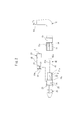
- FIG. 1 is a view showing the appearance of a vehicle sun visor shaft according to an embodiment of the present invention
- FIG. 1A is a perspective view
- FIG. 1B is a front view
- FIG. 2 is an exploded front view showing the vehicle sun visor shaft according to the embodiment of the present invention.
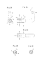
- 3A is a front view
- FIG. 3B is a left side view
- FIG. 3C is a bottom view
- FIG. 3D is a cross-sectional view along line AA
- FIG. 3E is a cross-sectional view along line BB.
- 4A and 4B are views showing a rotating shaft
- FIG. 4A is a front view
- FIG. 4B is a right side view
- FIG. 4C is a left side view
- FIG. 4D is a cross-sectional view taken along the line CC.
- 5A is a front view
- FIG. 5B is a plan view
- FIG. 5C is a right side view
- FIG. 5D is a left side view
- FIG. 5E is a sectional view taken along line DD.
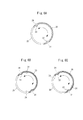
- 6A to 6C are cross-sectional views showing examples of the configuration of the click stationary recess and the click stationary convex.
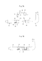
- 7 is a view showing another embodiment of the shaft for a vehicle sun visor according to the embodiment of the present invention.
- FIG. 7A is an exploded front view
- FIG. 7B is a front view.
- FIGS. 1A and 1B are views for explaining a shaft for a vehicle sun visor according to an embodiment of the present invention.
- the vehicle sun visor shaft of the present embodiment is a component that is used to rotatably support the sun visor, obliquely above the driver's seat and front passenger seat (the ceiling side of the passenger compartment).
- the vehicle sun visor shaft has an appearance as shown in FIGS. 1A and 1B, and includes a stationary shaft 10, a rotating shaft 20, a leaf spring member 30, and a damper member 40 as shown in FIG. It is out.
- the damper member 40 uses the well-known damper member 40 already marketed.
- the damper member 40 has a configuration in which an inner rotating body 42 is coaxially incorporated inside a cylindrical outer rotating case 41 and a viscous pair is filled between the outer rotating case 41 and the inner rotating body 42. In addition, a viscous resistance is applied to the rotational force acting between the outer rotating case 41 and the inner rotating body 42.
- the damper member 40 is housed inside the rotating shaft as will be described later, and has a function as a rotating resistance means for applying a rotating torque by viscous resistance to the rotational force from the rotating shaft.
- the fixed side shaft 10 has an L shape, and the base end 10a is fixed to the vehicle interior ceiling as a vehicle side fixing portion.
- a rotating shaft 20 is rotatably connected to the free end of the fixed shaft 10.
- the rotating shaft 20 has a simple rod-like appearance, is fixed to the sun visor, and rotates the sun visor integrally.
- a connecting outer cylinder 11 is formed in a cylindrical shape at the free end of the fixed shaft 10 so as to extend coaxially.
- an inner cylinder 21 is formed in a cylindrical shape at the base end of the rotating shaft 20 so as to extend coaxially.
- the outer peripheral surface of the inner cylinder 21 is a fitting portion that is fitted into the outer cylinder 11 formed at the free end of the fixed-side shaft 10.
- the rotating shaft 20 can be rotatably connected to the free end of the shaft 10.
- the outer cylinder 11 formed on the stationary shaft 10 has a locking claw 13 formed by cutting out the peripheral wall in the axial direction from the end face.
- an engagement groove 20 a extending around the entire circumference is formed at the root portion of the inner cylinder 21 in the rotating shaft 20.
- a fixed-side connecting shaft 14 extends on the central axis from the inner bottom of the outer cylinder 11 formed on the fixed-side shaft 10, while the center of the inner cylinder 21 formed on the rotating shaft 20 is also centered.
- a rotating side connecting shaft 22 extends on the shaft.
- the fixed-side connecting shaft 14 and the rotating-side connecting shaft 22 are rotatably connected to each other through a hollow portion 43 that passes through the central portion of the damper member 40 in the axial direction.
- the damper member 40 is accommodated coaxially in the inner cylinder 21 formed on the rotating shaft 20.
- a slit 21 a is formed in the axial direction on the peripheral wall of the inner cylinder 21, while a protrusion 41 a is formed in the axial direction on the outer periphery of the outer rotating case 41 of the damper member 40.
- the slits 21a and the ridges 41a function as detents for the damper member 40 with respect to the rotating shaft by engaging the ridges 41a with the slits 21a.
- the outer cylinder 11 formed on the fixed shaft 10 has an engagement recess 11a formed on the inner bottom, while an engagement protrusion 42a is formed on the end surface of the inner rotating body 42 of the damper member 40. is there.
- the rotation of the inner rotary body 42 of the damper member 40 with respect to the fixed side shaft 10 is restricted.
- the outer rotating case 41 of the damper member 40 is rotated together with the rotating shaft 20
- the accompanying rotation of the inner rotating body 42 is restricted, and the outer rotating case 41 and the inner rotating body 42 are relatively rotated.
- a viscous resistance is generated between the outer rotating case 41 and the inner rotating body 42.
- a fixed side spring mounting groove 15 for mounting the leaf spring member 30 is formed on the peripheral surface of the fixed side shaft 10 so as to extend in an arc shape in the circumferential direction with a certain width.
- the rotation shaft 20 is also provided with a rotation-side spring mounting portion 23 for mounting the leaf spring member 30 in a freely rotatable state on the outer peripheral surface dug down by one step.
- the rotary shaft 20 is formed with a click stationary recess 24 (locked portion) on the outer peripheral surface closer to the tip (inner cylinder 21) than the rotary spring mounting portion 23.
- the leaf spring member 30 includes an elastic support portion 34 in which a fixed side mounting portion 31, a rotation side mounting portion 32, and a click stationary convex portion 33 (locking portion) are formed. And a connecting portion 35.
- the fixed side mounting portion 31 is curved in an arc shape and is mounted in the fixed side spring mounting groove 15 formed in the fixed side shaft 10.
- the rotation side mounting portion 32 is also curved in an arc shape and is rotatably mounted on the rotation side spring mounting portion 23 of the rotation shaft 20.
- the click resting convex portion 33 constitutes a locking portion for resting the rotating shaft 20 with a click feeling, and inward from the position in the vicinity of the tip end portion of the elastic support portion 34 that is curved in an arc shape. It sticks out.
- the elastic support portion 34 is formed side by side with the rotation side mounting portion 32 with a retaining slit 30a therebetween.
- a retaining protrusion 25 extending in the circumferential direction is formed in part on the outer peripheral surface of the rotating shaft 20, and the retaining protrusion 25 is disposed in the retaining slit 30 a of the leaf spring member 30.
- the leaf spring member 30 prevents the rotational shaft 20 from coming off in the axial direction with respect to the stationary shaft 10.
- the vehicle sun visor shaft composed of the above-described parts is first fitted into the outer cylinder 11 formed on the stationary shaft 10 after the damper member 40 is housed in the inner cylinder 21 of the rotating shaft 20.
- the locking claw 13 is locked in the engaging groove 20a.
- the protrusion 41a of the damper member 40 is engaged with the slit 21a formed in the inner cylinder 21 of the rotating shaft 20, and the engagement protrusion of the damper member 40 is engaged with the engagement recess 11a at the inner bottom of the outer cylinder 11.
- the part 42a is engaged.
- the leaf spring member 30 is mounted so as to span between the fixed side shaft 10 and the rotating shaft 20.
- the stationary side mounting portion 31 of the leaf spring member 30 is elastically fitted into the stationary side spring mounting groove 15 of the stationary side shaft 10, and the rotational side mounting portion 32 of the leaf spring member 30 is inserted into the rotational shaft 20. It fits in the rotation side spring mounting part 23 elastically.
- the click stationary convex portion 33 of the leaf spring member 30 is in contact with the outer peripheral surface of the rotating shaft 20 and engages with the click stationary concave portion 24 formed in the rotating shaft 20 as the rotating shaft 20 rotates. To do.
- This engaging operation is executed with a click feeling by the spring force of the leaf spring member 30.
- the click stationary recess 24 (locked portion) formed on the rotation shaft 20 and the leaf spring member 30 have a click feeling at a preset rotation angle when the rotation shaft 20 rotates.
- the click stationary means for maintaining the stationary state is configured.
- the click stationary recess 24 (locked portion) is preferably formed arbitrarily corresponding to the position where the sun visor mounted on the rotating shaft 20 is desired to be stationary.
- the click stationary recesses 24 are formed at two positions separated by 180 °, and the click stationary convex portions 33 (locking portions) are also formed at two positions separated by 180 °. Each time the shaft 20 rotates 180 °, the click stationary convex portion 33 engages with the click stationary concave portion 24.
- FIGS. 6B and 6C two pairs of click resting recesses 24 spaced apart by 180 ° are used as a pair, and a total of two pairs of click resting recesses 24 are formed.
- the leaf spring member 30 has click resting convex portions 33 (locking portions) formed at two positions separated by 180 °. Each time the click resting recess 24 is engaged, it can be stopped with a click feeling.
- the fixed side shaft 10 having an L-shaped complicated shape is not related to the function for keeping the sun visor stationary at an arbitrary rotation angle, and can therefore be used in common for all vehicle types.
- the change of the sun visor stationary holding position for each vehicle type can be easily handled by simply replacing the rotary shaft 20 having a simple rod-like shape to be formed with the click stationary recess 24 (locked portion). It becomes possible.
- the fixed side shaft 10 can be used in common.
- the shape of the click stationary recess 24 (locked portion) can be replaced with a convex portion
- the shape of the click stationary convex portion 33 (locking portion) can be replaced with a concave portion.
- FIGS. 7A and 7B as a connecting means for the fixed side shaft 10 and the rotating shaft 20, a configuration including an iron core and a fitting groove is employed instead of the outer cylinder 11 and the inner cylinder 21 described above. You can also. That is, the iron core 50 extends coaxially from the free end of the fixed shaft 10, while the fitting groove 51 is formed coaxially from the proximal end of the rotating shaft 20 toward the inside of the shaft. By fitting the iron core 50 into the fitting groove 51, the rotating shaft 20 can be connected to the fixed side shaft 10.
- the damper member 40 is built in the distal end portion of the fixed side shaft 10, and an engagement recess 11 a that engages with the engagement protrusion 42 a of the damper member 40 is formed on the base end surface of the rotating shaft 20.
- the iron core can be extended from the rotating shaft 20.
Landscapes
- Engineering & Computer Science (AREA)
- Mechanical Engineering (AREA)
- Pivots And Pivotal Connections (AREA)
Abstract
基端が車室天井面に固定されるL字状の固定側シャフト10と、固定側シャフト10の自由端に回動自在に連結され、サンバイザとともに回動する棒状の回動シャフト20と、回動シャフト20が回動した際、あらかじめ設定した回動角度においてクリック感をもって静止状態を保持する板ばね部材30を備えた構成とする。このように構成することで、L字状の複雑な形状をした固定側シャフト10は、サンバイザを任意の回動角度で静止させておくための機能に関連しないため、すべての車種に共通して用いることができ、車種毎のサンバイザの静止保持位置の変更には、棒状の簡素な形状をした回動シャフト20の交換で簡易に対応することが可能となる。
Description
この発明は、車両の運転席や助手席の前上方に太陽光線を遮る目的で取り付けられるサンバイザに係り、特に当該サンバイザを車両の天井面に固定するための車両サンバイザ用シャフトに関する。
従来、サンバイザを車両の天井面に固定するには、L字形のシャフトを用いている。例えば、特許文献1に開示されたサンバイザの取付け構造は、車体に固定されたシャフトに、サポートを介してサンバイザ本体が回転自在に支持されている。サポートは、サンバイザ本体に内蔵され、このサポートに二股状のスプリングが取付けられている。シャフトはこの二股状のスプリングに挟持されている。
一般に、サンバイザは、天井面近くに持ち上げた収納位置やその他適宜の回動位置で静止状態を保持する構造となっている。特許文献1に開示されたサンバイザの取付け構造にあっては、シャフトの周面に面取部を適宜形成し、この面取部に二股状のスプリングの平坦部を面接触させることで挟持力を強めている。この挟持力により、サンバイザが回動位置にて静止状態を保持される。
シャフトの周面において、面取部の形成位置は、サンバイザを静止させておきたい回動角度位置に対応して設定される。
シャフトの周面において、面取部の形成位置は、サンバイザを静止させておきたい回動角度位置に対応して設定される。
さて、サンバイザを静止させておきたい回動角度位置は、車両によりまちまちである。例えば、天井面に対するフロントガラスの傾斜角度が相違するだけで、サンバイザが天井に近接対向した位置(通常、当該位置が収納位置となる)から、フロントガラスに近接対向する位置(通常、当該位置が全開位置となる)までの回動角度は違ってくる。
したがって、上述した従来の構造では、車種毎に平坦部の形成位置が調整されたL字形をした複雑な形状のシャフト全体を用意する必要があり、煩雑な製造計画や在庫管理を強いられる課題があった。
したがって、上述した従来の構造では、車種毎に平坦部の形成位置が調整されたL字形をした複雑な形状のシャフト全体を用意する必要があり、煩雑な製造計画や在庫管理を強いられる課題があった。
本発明は、上述した事情に鑑みてなされたもので、サンバイザの静止保持位置の変更に簡易に対応できる車両サンバイザ用シャフトの提供を目的とする。
上記目的を達成するために、本発明は、基端が車室天井面に固定されるL字状の固定側シャフトと、
前記固定側シャフトの自由端に回動自在に連結され、サンバイザとともに回動する棒状の回動シャフトと、
前記回動シャフトが回動した際、あらかじめ設定した回動角度においてクリック感をもって静止状態を保持するクリック静止手段と、
を備えた構成としてある。
前記固定側シャフトの自由端に回動自在に連結され、サンバイザとともに回動する棒状の回動シャフトと、
前記回動シャフトが回動した際、あらかじめ設定した回動角度においてクリック感をもって静止状態を保持するクリック静止手段と、
を備えた構成としてある。
上述した構成の本発明によれば、基端が車室天井面に固定される固定側シャフトと、この固定側シャフトの自由端に回動自在に連結される回動シャフトに分け、回動シャフトのみサンバイザとともに回動するように構成したので、L字状の複雑な形状をした固定側シャフトは、サンバイザを任意の回動角度で静止させておくための機能に関連しないため、すべての車種に共通して用いることができ、車種毎のサンバイザの静止保持位置の変更には、棒状の簡素な形状をした回動シャフトの交換で簡易に対応することが可能となる。
10:固定側シャフト、11:外筒、11a:係合凹部、13:係止爪、14:固定側連結軸、15:固定側ばね装着溝、
20:回動シャフト、20a:係合溝、21:内筒、21a:スリット、22:回動側連結軸、23:回動側ばね装着部、24:クリック静止用凹部、25:抜止め用凸条、
30:板ばね部材、30a:抜止め用スリット、31:固定側装着部、32:回動側装着部、33:クリック静止用凸部、34:弾性支持部、35:連結部、
40:ダンパ部材、41:外側回転ケース、41a:凸条、42:内側回転体、42a:係合凸部、43:中空部、
50:鉄芯、51:嵌合溝
20:回動シャフト、20a:係合溝、21:内筒、21a:スリット、22:回動側連結軸、23:回動側ばね装着部、24:クリック静止用凹部、25:抜止め用凸条、
30:板ばね部材、30a:抜止め用スリット、31:固定側装着部、32:回動側装着部、33:クリック静止用凸部、34:弾性支持部、35:連結部、
40:ダンパ部材、41:外側回転ケース、41a:凸条、42:内側回転体、42a:係合凸部、43:中空部、
50:鉄芯、51:嵌合溝
以下、この発明の実施の形態について図面を参照して詳細に説明する。
図1~図6は本発明の実施形態に係る車両サンバイザ用シャフトを説明するための図である。
本実施形態の車両サンバイザ用シャフトは、自動車の運転席及び助手席の斜め上方(車室の天井側)で、サンバイザーを回動自在に支持するために用いられる部品である。この車両サンバイザ用シャフト、図1A、図1Bに示すような外観をしており、図2に示すとおり固定側シャフト10と、回動シャフト20と、板ばね部材30と、ダンパ部材40とを含んでいる。
図1~図6は本発明の実施形態に係る車両サンバイザ用シャフトを説明するための図である。
本実施形態の車両サンバイザ用シャフトは、自動車の運転席及び助手席の斜め上方(車室の天井側)で、サンバイザーを回動自在に支持するために用いられる部品である。この車両サンバイザ用シャフト、図1A、図1Bに示すような外観をしており、図2に示すとおり固定側シャフト10と、回動シャフト20と、板ばね部材30と、ダンパ部材40とを含んでいる。
このうち、ダンパ部材40は、既に市販されている公知のダンパ部材40を利用している。このダンパ部材40は、円筒状をした外側回転ケース41の内部に同軸上に内側回転体42を組み込み、こられ外側回転ケース41と内側回転体42との間に粘性対を充填した構成となっており、外側回転ケース41と内側回転体42との間に作用する回転力に対して粘性抵抗を付与する。
このダンパ部材40は、後述するとおり回転シャフトの内部に収納され、回転シャフトからの回動力に対して粘性抵抗による回動トルクを付与する回動抵抗手段としての機能を有している。
このダンパ部材40は、後述するとおり回転シャフトの内部に収納され、回転シャフトからの回動力に対して粘性抵抗による回動トルクを付与する回動抵抗手段としての機能を有している。
固定側シャフト10は、L字形状をしており、基端10aが車両側固定部として自動車の車室天井面に固定される。固定側シャフト10の自由端には、回動シャフト20が回動自在に連結される。回動シャフト20は、棒状の簡素な外観形状をしており、サンバイザに固定されて当該サンバイザを一体に回動させる。
ここで、固定側シャフト10の自由端には、図3A~図3Eに示すように、同軸上に延出して連結用の外筒11が円筒状に形成してある。一方、回動シャフト20の基端には、図4A~図4Dに示すように、同軸上に延出して内筒21が円筒状に形成してある。この内筒21の外周面は、固定側シャフト10の自由端に形成した外筒11に嵌め込まれる嵌合部となっており、外筒11の内側に内筒21を嵌め込むだけで、固定側シャフト10の自由端に回動シャフト20を回動自在に連結できる構成としてある。
ここで、固定側シャフト10の自由端には、図3A~図3Eに示すように、同軸上に延出して連結用の外筒11が円筒状に形成してある。一方、回動シャフト20の基端には、図4A~図4Dに示すように、同軸上に延出して内筒21が円筒状に形成してある。この内筒21の外周面は、固定側シャフト10の自由端に形成した外筒11に嵌め込まれる嵌合部となっており、外筒11の内側に内筒21を嵌め込むだけで、固定側シャフト10の自由端に回動シャフト20を回動自在に連結できる構成としてある。
固定側シャフト10に形成した外筒11には、周壁を端面から軸方向に切り欠いて係止爪13が形成してある。一方、回動シャフト20における内筒21の根元部分には、全周に延びる係合溝20aが形成してある。そして、固定側シャフト10に形成した外筒11に、回動シャフト20の内筒21を嵌合したとき、係止爪13が係合溝20aに係合して、固定側シャフト10と回動シャフト20の軸方向の位置決めがなされる。
なお、固定側シャフト10に形成した外筒11の内底部からは中心軸上に固定側連結軸14が延出しており、一方、回動シャフト20に形成した内筒21の内底部からも中心軸上に回動側連結軸22が延出している。これら固定側連結軸14と回動側連結軸22は、ダンパ部材40の中心部分を軸方向に貫通する中空部43を透して互いの先端部が回動自在に連結される。
回動シャフト20に形成した内筒21には、ダンパ部材40が同軸状に収納される。内筒21の周壁には軸方向にスリット21aが形成してあり、一方、ダンパ部材40の外側回転ケース41の外周には、軸方向に凸条41aが形成してある。これらスリット21aと凸条41aは、ダンパ部材40を内筒21に収納する際、凸条41aをスリット21aに係合させることで、回転シャフトに対するダンパ部材40の回り止めとして機能する。
固定側シャフト10に形成した外筒11には、内底部に係合凹部11aが形成してあり、一方、ダンパ部材40の内側回転体42の端面には、係合凸部42aが形成してある。この係合凹部11aを係合凸部42aに係止することで、ダンパ部材40の内側回転体42の固定側シャフト10に対する回動が規制される。これにより、回動シャフト20とともにダンパ部材40の外側回転ケース41が回動した際に、内側回転体42の連れ回りが規制されて、外側回転ケース41と内側回転体42とが相対的に回動する。そして、この回動動作に伴い外側回転ケース41と内側回転体42との間に粘性抵抗が生じる。
また、固定側シャフト10の周面には、板ばね部材30を装着するための固定側ばね装着溝15が、一定の幅で円周方向に円弧状に延びて形成してある。また、回動シャフト20にも、一段掘り下げた外周面に、板ばね部材30を回動自在な状態で装着するための回動側ばね装着部23が形成してある。さらに、回動シャフト20には、この回動側ばね装着部23よりも先端(内筒21)寄りの外周面に、クリック静止用凹部24(被係止部)が形成してある。
板ばね部材30は、図5A~図5Eに示すように、固定側装着部31と、回動側装着部32と、クリック静止用凸部33(係止部)が形成された弾性支持部34と、連結部35とを含んでいる。
固定側装着部31は、円弧状に湾曲形成してあり、固定側シャフト10に形成した固定側ばね装着溝15に装着される。回動側装着部32も円弧状に湾曲形成してあり、回動シャフト20の回動側ばね装着部23へ回動自在に装着される。
固定側装着部31は、円弧状に湾曲形成してあり、固定側シャフト10に形成した固定側ばね装着溝15に装着される。回動側装着部32も円弧状に湾曲形成してあり、回動シャフト20の回動側ばね装着部23へ回動自在に装着される。
クリック静止用凸部33は、クリック感をもって回動シャフト20を静止させるための係止部を構成しており、円弧状に湾曲形成された弾性支持部34の先端部近傍位置から内側へ向かって突き出している。このクリック静止用凸部33を、回動シャフト20に形成したクリック静止用凹部24に係合させることで、クリック感をもって回動シャフト20を当該回動位置に静止させることができる。弾性支持部34は、抜止め用スリット30aを隔てて回動側装着部32と並べて形成してある。
回動シャフト20の外周面には、円周方向に延びる抜止め用凸条25が一部に形成してあり、板ばね部材30の抜止め用スリット30a内にこの抜止め用凸条25を配置することで、板ばね部材30により固定側シャフト10に対する回動シャフト20の軸方向の抜けが防止される。
上述した各部品からなる車両サンバイザ用シャフトは、まず、回動シャフト20の内筒21にダンパ部材40を収納されてから、当該内筒21を固定側シャフト10に形成した外筒11に嵌め込み、係止爪13を係合溝20aに係止させる。このとき、ダンパ部材40の凸条41aを回動シャフト20の内筒21に形成したスリット21aに係合させるとともに、外筒11の内底部にある係合凹部11aにダンパ部材40の係合凸部42aを係合させる。
その後、板ばね部材30を固定側シャフト10と回動シャフト20との間に架け渡すようにして装着する。このとき、板ばね部材30の固定側装着部31を固定側シャフト10の固定側ばね装着溝15へ弾力的に嵌め込むとともに、板ばね部材30の回動側装着部32を回動シャフト20の回動側ばね装着部23へ弾力的に嵌め込む。
その後、板ばね部材30を固定側シャフト10と回動シャフト20との間に架け渡すようにして装着する。このとき、板ばね部材30の固定側装着部31を固定側シャフト10の固定側ばね装着溝15へ弾力的に嵌め込むとともに、板ばね部材30の回動側装着部32を回動シャフト20の回動側ばね装着部23へ弾力的に嵌め込む。
板ばね部材30のクリック静止用凸部33は、回動シャフト20の外周面に当接しており、回動シャフト20の回転に伴い、回動シャフト20に形成したクリック静止用凹部24に係合する。この係合動作は、板ばね部材30のばね力によりクリック感をもって実行される。
このように、回動シャフト20に形成したクリック静止用凹部24(被係止部)と、板ばね部材30は、回動シャフト20が回動した際、あらかじめ設定した回動角度においてクリック感をもって静止状態を保持するクリック静止手段を構成する。
このように、回動シャフト20に形成したクリック静止用凹部24(被係止部)と、板ばね部材30は、回動シャフト20が回動した際、あらかじめ設定した回動角度においてクリック感をもって静止状態を保持するクリック静止手段を構成する。
クリック静止用凹部24(被係止部)は、回動シャフト20に装着されるサンバイザを静止させたい位置に対応して任意に形成することが好ましい。
図6Aに示す構成例では、クリック静止用凹部24を、180゜隔てた2箇所に形成するとともに、クリック静止用凸部33(係止部)も180゜隔てた2箇所に形成し、回動シャフト20が180゜回動する毎にクリック静止用凸部33がクリック静止用凹部24に係合する。
また、図6B、図6Cに示す構成例では、180゜隔てた2箇所のクリック静止用凹部24を一対として、合計2対のクリック静止用凹部24が形成してある。板ばね部材30には、クリック静止用凸部33(係止部)が180゜隔てた2箇所に形成してあり、回動シャフト20は、これらクリック静止用凸部33がいずれかの対のクリック静止用凹部24に係合する毎に、クリック感をもって静止することができる。
図6Aに示す構成例では、クリック静止用凹部24を、180゜隔てた2箇所に形成するとともに、クリック静止用凸部33(係止部)も180゜隔てた2箇所に形成し、回動シャフト20が180゜回動する毎にクリック静止用凸部33がクリック静止用凹部24に係合する。
また、図6B、図6Cに示す構成例では、180゜隔てた2箇所のクリック静止用凹部24を一対として、合計2対のクリック静止用凹部24が形成してある。板ばね部材30には、クリック静止用凸部33(係止部)が180゜隔てた2箇所に形成してあり、回動シャフト20は、これらクリック静止用凸部33がいずれかの対のクリック静止用凹部24に係合する毎に、クリック感をもって静止することができる。
このように、L字状の複雑な形状をした固定側シャフト10は、サンバイザを任意の回動角度で静止させておくための機能に関連しないため、すべての車種に共通して用いることができ、車種毎のサンバイザの静止保持位置の変更には、クリック静止用凹部24(被係止部)の形成対象となる棒状の簡素な形状をした回動シャフト20の交換だけで、簡易に対応することが可能となる。
なお、サンバイザを静止させる角度によっては、クリック静止用凸部33(係止部)の形成位置も変更を加えた複数の板ばね部材30を用意する必要が生じることもあるが、その場合であっても固定側シャフト10は共通に利用することができる。
なお、サンバイザを静止させる角度によっては、クリック静止用凸部33(係止部)の形成位置も変更を加えた複数の板ばね部材30を用意する必要が生じることもあるが、その場合であっても固定側シャフト10は共通に利用することができる。
以上、本発明の実施形態について説明してきたが、本発明は上述した実施形態に限定されるものではない。
例えば、クリック静止用凹部24(被係止部)の形状を凸部に代えるとともに、クリック静止用凸部33(係止部)の形状を凹部に代えることもできる。
例えば、クリック静止用凹部24(被係止部)の形状を凸部に代えるとともに、クリック静止用凸部33(係止部)の形状を凹部に代えることもできる。
また、図7A、図7Bに示すように、固定側シャフト10と回動シャフト20の連結手段として、上述した外筒11および内筒21に代えて、鉄芯と嵌合溝による構成を採用することもできる。すなわち、固定側シャフト10の自由端から同軸上に鉄芯50を延出し、一方、回動シャフト20の基端からシャフト内部に向かって同軸上に嵌合溝51を形成する。この嵌合溝51に鉄芯50を嵌合することで、固定側シャフト10に回動シャフト20を連結することができる。
ダンパ部材40は固定側シャフト10の先端部に内蔵し、回動シャフト20の基端面には、ダンパ部材40の係合凸部42aが係合する係合凹部11aが形成してある。
なお、固定側シャフト10に嵌合溝を形成するとともに、回動シャフト20から鉄芯を延出させることもできる。
ダンパ部材40は固定側シャフト10の先端部に内蔵し、回動シャフト20の基端面には、ダンパ部材40の係合凸部42aが係合する係合凹部11aが形成してある。
なお、固定側シャフト10に嵌合溝を形成するとともに、回動シャフト20から鉄芯を延出させることもできる。
Claims (9)
- 基端が車室天井面に固定されるL字状の固定側シャフトと、
前記固定側シャフトの自由端に回動自在に連結され、サンバイザとともに回動する棒状の回動シャフトと、
前記回動シャフトが回動した際、あらかじめ設定した回動角度において静止状態を保持する静止手段と、を備えた車両サンバイザ用シャフト。 - 前記静止手段は、
前記回動シャフトの周面に形成した被係止部と、
係止部を有し、前記回動シャフトの周面にばね力を付勢して前記係止部を前記被係止部に係止させる板ばね部材と、を含む請求項1の車両サンバイザ用シャフト。 - 前記被係止部と係止部は、一方が凹部で形成してあり、他方が当該凹部に係合する凸部で形成してある請求項2の車両サンバイザ用シャフト。
- 前記板ばね部材は、
前記固定側シャフトの周面に装着される固定側装着部と、
前記回動シャフトに対し相対的に回動自在な状態で当該回動シャフトの周面に装着される回動側装着部と、
前記係止部が形成され、当該係止部を前記回転シャフトの周面に押圧付勢する弾性支持部と、
前記固定側装着部、回動側装着部および弾性支持部を連結して一体とする連結部と、を含む請求項3の車両サンバイザ用シャフト。 - 前記回動シャフトの回動に対して回動トルクを付与する回動抵抗手段を備える請求項4の車両サンバイザ用シャフト。
- 前記回動抵抗手段がダンパ部材で構成されており、当該ダンパ部材は、外側回転ケースと、この外側回転ケース内に同軸上に組み込まれた内側回転体と、これら外側回転ケースと内側回転体との間に充填され、前記外側回転ケースと内側回転体との間に作用する回転力に対して粘性抵抗を付与する粘性体とを含み、前記回転シャフトからの回動力を前記外側回転ケースおよび内側回転体の間に伝え、当該回転力に対して粘性抵抗を付与する構成である請求項5の車両サンバイザ用シャフト。
- 前記ダンパ部材は、前記固定側シャフトまたは回動シャフトのいずれか一方に同軸状に収納される請求項6の車両サンバイザ用シャフト。
- 前記固定側シャフトの自由端および前記回動シャフトの基端の一方に同軸上に延出して連結用の外筒を形成するとともに、他方には同軸上に延出して嵌合部を形成し、前記外筒に前記嵌合部を嵌合することで前記固定側シャフトに前記回動シャフトを連結する構成とした請求項7の車両サンバイザ用シャフト。
- 前記固定側シャフトの自由端および前記回動シャフトの基端の一方から同軸上に鉄芯を延出するとともに、他方からシャフト内部に向かって同軸上に嵌合溝を形成し、前記鉄芯を前嵌合溝に嵌合することで前記固定側シャフトに前記回動シャフトを連結する構成とした請求項7の車両サンバイザ用シャフト。
Priority Applications (1)
| Application Number | Priority Date | Filing Date | Title |
|---|---|---|---|
| JP2013507475A JP5477880B2 (ja) | 2011-03-31 | 2012-03-23 | 車両サンバイザ用シャフト |
Applications Claiming Priority (2)
| Application Number | Priority Date | Filing Date | Title |
|---|---|---|---|
| JP2011078242 | 2011-03-31 | ||
| JP2011-078242 | 2011-03-31 |
Publications (1)
| Publication Number | Publication Date |
|---|---|
| WO2012133139A1 true WO2012133139A1 (ja) | 2012-10-04 |
Family
ID=46930865
Family Applications (1)
| Application Number | Title | Priority Date | Filing Date |
|---|---|---|---|
| PCT/JP2012/057433 Ceased WO2012133139A1 (ja) | 2011-03-31 | 2012-03-23 | 車両サンバイザ用シャフト |
Country Status (2)
| Country | Link |
|---|---|
| JP (1) | JP5477880B2 (ja) |
| WO (1) | WO2012133139A1 (ja) |
Citations (6)
| Publication number | Priority date | Publication date | Assignee | Title |
|---|---|---|---|---|
| JPS56147118U (ja) * | 1980-04-08 | 1981-11-06 | ||
| JPS5711114A (en) * | 1980-06-20 | 1982-01-20 | Kasai Kogyo Co Ltd | Sun visor for car |
| JPS57166916U (ja) * | 1981-04-16 | 1982-10-21 | ||
| JPH0360116U (ja) * | 1989-10-17 | 1991-06-13 | ||
| JPH11157334A (ja) * | 1997-11-28 | 1999-06-15 | Mutsuwa Kogyo Kk | 車両用サンバイザ |
| JP2000190725A (ja) * | 2000-01-01 | 2000-07-11 | Neoex Lab Inc | 車両用サンバイザの支軸構造 |
-
2012
- 2012-03-23 WO PCT/JP2012/057433 patent/WO2012133139A1/ja not_active Ceased
- 2012-03-23 JP JP2013507475A patent/JP5477880B2/ja not_active Expired - Fee Related
Patent Citations (6)
| Publication number | Priority date | Publication date | Assignee | Title |
|---|---|---|---|---|
| JPS56147118U (ja) * | 1980-04-08 | 1981-11-06 | ||
| JPS5711114A (en) * | 1980-06-20 | 1982-01-20 | Kasai Kogyo Co Ltd | Sun visor for car |
| JPS57166916U (ja) * | 1981-04-16 | 1982-10-21 | ||
| JPH0360116U (ja) * | 1989-10-17 | 1991-06-13 | ||
| JPH11157334A (ja) * | 1997-11-28 | 1999-06-15 | Mutsuwa Kogyo Kk | 車両用サンバイザ |
| JP2000190725A (ja) * | 2000-01-01 | 2000-07-11 | Neoex Lab Inc | 車両用サンバイザの支軸構造 |
Also Published As
| Publication number | Publication date |
|---|---|
| JP5477880B2 (ja) | 2014-04-23 |
| JPWO2012133139A1 (ja) | 2014-07-28 |
Similar Documents
| Publication | Publication Date | Title |
|---|---|---|
| GB2531900A (en) | Lock cylinder mechanism capable of preventing violent damage | |
| US20200370348A1 (en) | Hinge | |
| JP5294007B2 (ja) | ラック軸支持装置および車両用操舵装置 | |
| JP3212614U (ja) | 調節器具 | |
| US11731534B2 (en) | Actuating drive for a motor vehicle, comprising an electronic motor, a transmission, and a spindle | |
| JP2016159721A (ja) | ベンチレータ構造 | |
| CN104145068B (zh) | 车辆的把手装置 | |
| JP4555657B2 (ja) | 筆記具 | |
| US9377633B2 (en) | Resilient hinge for spectacles | |
| JP3948901B2 (ja) | 手動格納式ドアミラー | |
| KR20190015550A (ko) | 풍향조정장치 | |
| JP5477880B2 (ja) | 車両サンバイザ用シャフト | |
| CN103510829B (zh) | 日射遮蔽装置 | |
| JP2010210062A (ja) | ラック軸支持装置および車両用操舵装置 | |
| WO2014092134A1 (ja) | ロック装置 | |
| EP2607217A1 (en) | Kickstand | |
| WO2006115964A3 (en) | Earphone with selectable cable position | |
| JP2010190030A (ja) | シリンダ錠 | |
| WO2015008535A1 (ja) | 車両用ミラー装置 | |
| CN219613281U (zh) | 可转动的化妆镜 | |
| JP6203680B2 (ja) | 車両用コンソールのヒンジ機構 | |
| CN111271368B (zh) | 旋转轴结构 | |
| JP3164942U (ja) | ハンドル装置 | |
| JP2005127013A (ja) | ドア用ヒンジ | |
| WO2009064187A1 (en) | Device for holding an ancillary device at right angles to an imaginary axis of rotation |
Legal Events
| Date | Code | Title | Description |
|---|---|---|---|
| 121 | Ep: the epo has been informed by wipo that ep was designated in this application |
Ref document number: 12764413 Country of ref document: EP Kind code of ref document: A1 |
|
| DPE1 | Request for preliminary examination filed after expiration of 19th month from priority date (pct application filed from 20040101) | ||
| ENP | Entry into the national phase |
Ref document number: 2013507475 Country of ref document: JP Kind code of ref document: A |
|
| NENP | Non-entry into the national phase |
Ref country code: DE |
|
| 122 | Ep: pct application non-entry in european phase |
Ref document number: 12764413 Country of ref document: EP Kind code of ref document: A1 |