WO2012132996A1 - 駆動力配分制御装置及び四輪駆動車 - Google Patents
駆動力配分制御装置及び四輪駆動車 Download PDFInfo
- Publication number
- WO2012132996A1 WO2012132996A1 PCT/JP2012/057020 JP2012057020W WO2012132996A1 WO 2012132996 A1 WO2012132996 A1 WO 2012132996A1 JP 2012057020 W JP2012057020 W JP 2012057020W WO 2012132996 A1 WO2012132996 A1 WO 2012132996A1
- Authority
- WO
- WIPO (PCT)
- Prior art keywords
- wheel
- driving force
- torque
- rotational speed
- control device
- Prior art date
- Legal status (The legal status is an assumption and is not a legal conclusion. Google has not performed a legal analysis and makes no representation as to the accuracy of the status listed.)
- Ceased
Links
Images




Classifications
-
- B—PERFORMING OPERATIONS; TRANSPORTING
- B60—VEHICLES IN GENERAL
- B60K—ARRANGEMENT OR MOUNTING OF PROPULSION UNITS OR OF TRANSMISSIONS IN VEHICLES; ARRANGEMENT OR MOUNTING OF PLURAL DIVERSE PRIME-MOVERS IN VEHICLES; AUXILIARY DRIVES FOR VEHICLES; INSTRUMENTATION OR DASHBOARDS FOR VEHICLES; ARRANGEMENTS IN CONNECTION WITH COOLING, AIR INTAKE, GAS EXHAUST OR FUEL SUPPLY OF PROPULSION UNITS IN VEHICLES
- B60K17/00—Arrangement or mounting of transmissions in vehicles
- B60K17/34—Arrangement or mounting of transmissions in vehicles for driving both front and rear wheels, e.g. four wheel drive vehicles
- B60K17/348—Arrangement or mounting of transmissions in vehicles for driving both front and rear wheels, e.g. four wheel drive vehicles having differential means for driving one set of wheels, e.g. the front, at one speed and the other set, e.g. the rear, at a different speed
-
- B—PERFORMING OPERATIONS; TRANSPORTING
- B60—VEHICLES IN GENERAL
- B60K—ARRANGEMENT OR MOUNTING OF PROPULSION UNITS OR OF TRANSMISSIONS IN VEHICLES; ARRANGEMENT OR MOUNTING OF PLURAL DIVERSE PRIME-MOVERS IN VEHICLES; AUXILIARY DRIVES FOR VEHICLES; INSTRUMENTATION OR DASHBOARDS FOR VEHICLES; ARRANGEMENTS IN CONNECTION WITH COOLING, AIR INTAKE, GAS EXHAUST OR FUEL SUPPLY OF PROPULSION UNITS IN VEHICLES
- B60K17/00—Arrangement or mounting of transmissions in vehicles
- B60K17/34—Arrangement or mounting of transmissions in vehicles for driving both front and rear wheels, e.g. four wheel drive vehicles
- B60K17/348—Arrangement or mounting of transmissions in vehicles for driving both front and rear wheels, e.g. four wheel drive vehicles having differential means for driving one set of wheels, e.g. the front, at one speed and the other set, e.g. the rear, at a different speed
- B60K17/35—Arrangement or mounting of transmissions in vehicles for driving both front and rear wheels, e.g. four wheel drive vehicles having differential means for driving one set of wheels, e.g. the front, at one speed and the other set, e.g. the rear, at a different speed including arrangements for suppressing or influencing the power transfer, e.g. viscous clutches
-
- B—PERFORMING OPERATIONS; TRANSPORTING
- B60—VEHICLES IN GENERAL
- B60K—ARRANGEMENT OR MOUNTING OF PROPULSION UNITS OR OF TRANSMISSIONS IN VEHICLES; ARRANGEMENT OR MOUNTING OF PLURAL DIVERSE PRIME-MOVERS IN VEHICLES; AUXILIARY DRIVES FOR VEHICLES; INSTRUMENTATION OR DASHBOARDS FOR VEHICLES; ARRANGEMENTS IN CONNECTION WITH COOLING, AIR INTAKE, GAS EXHAUST OR FUEL SUPPLY OF PROPULSION UNITS IN VEHICLES
- B60K23/00—Arrangement or mounting of control devices for vehicle transmissions, or parts thereof, not otherwise provided for
- B60K23/08—Arrangement or mounting of control devices for vehicle transmissions, or parts thereof, not otherwise provided for for changing number of driven wheels, for switching from driving one axle to driving two or more axles
- B60K23/0808—Arrangement or mounting of control devices for vehicle transmissions, or parts thereof, not otherwise provided for for changing number of driven wheels, for switching from driving one axle to driving two or more axles for varying torque distribution between driven axles, e.g. by transfer clutch
-
- B—PERFORMING OPERATIONS; TRANSPORTING
- B60—VEHICLES IN GENERAL
- B60W—CONJOINT CONTROL OF VEHICLE SUB-UNITS OF DIFFERENT TYPE OR DIFFERENT FUNCTION; CONTROL SYSTEMS SPECIALLY ADAPTED FOR HYBRID VEHICLES; ROAD VEHICLE DRIVE CONTROL SYSTEMS FOR PURPOSES NOT RELATED TO THE CONTROL OF A PARTICULAR SUB-UNIT
- B60W30/00—Purposes of road vehicle drive control systems not related to the control of a particular sub-unit, e.g. of systems using conjoint control of vehicle sub-units
- B60W30/18—Propelling the vehicle
-
- B—PERFORMING OPERATIONS; TRANSPORTING
- B60—VEHICLES IN GENERAL
- B60W—CONJOINT CONTROL OF VEHICLE SUB-UNITS OF DIFFERENT TYPE OR DIFFERENT FUNCTION; CONTROL SYSTEMS SPECIALLY ADAPTED FOR HYBRID VEHICLES; ROAD VEHICLE DRIVE CONTROL SYSTEMS FOR PURPOSES NOT RELATED TO THE CONTROL OF A PARTICULAR SUB-UNIT
- B60W2510/00—Input parameters relating to a particular sub-units
- B60W2510/06—Combustion engines, Gas turbines
- B60W2510/0638—Engine speed
-
- B—PERFORMING OPERATIONS; TRANSPORTING
- B60—VEHICLES IN GENERAL
- B60W—CONJOINT CONTROL OF VEHICLE SUB-UNITS OF DIFFERENT TYPE OR DIFFERENT FUNCTION; CONTROL SYSTEMS SPECIALLY ADAPTED FOR HYBRID VEHICLES; ROAD VEHICLE DRIVE CONTROL SYSTEMS FOR PURPOSES NOT RELATED TO THE CONTROL OF A PARTICULAR SUB-UNIT
- B60W2520/00—Input parameters relating to overall vehicle dynamics
- B60W2520/10—Longitudinal speed
-
- B—PERFORMING OPERATIONS; TRANSPORTING
- B60—VEHICLES IN GENERAL
- B60W—CONJOINT CONTROL OF VEHICLE SUB-UNITS OF DIFFERENT TYPE OR DIFFERENT FUNCTION; CONTROL SYSTEMS SPECIALLY ADAPTED FOR HYBRID VEHICLES; ROAD VEHICLE DRIVE CONTROL SYSTEMS FOR PURPOSES NOT RELATED TO THE CONTROL OF A PARTICULAR SUB-UNIT
- B60W2520/00—Input parameters relating to overall vehicle dynamics
- B60W2520/26—Wheel slip
- B60W2520/263—Slip values between front and rear axle
-
- B—PERFORMING OPERATIONS; TRANSPORTING
- B60—VEHICLES IN GENERAL
- B60W—CONJOINT CONTROL OF VEHICLE SUB-UNITS OF DIFFERENT TYPE OR DIFFERENT FUNCTION; CONTROL SYSTEMS SPECIALLY ADAPTED FOR HYBRID VEHICLES; ROAD VEHICLE DRIVE CONTROL SYSTEMS FOR PURPOSES NOT RELATED TO THE CONTROL OF A PARTICULAR SUB-UNIT
- B60W2540/00—Input parameters relating to occupants
- B60W2540/10—Accelerator pedal position
-
- B—PERFORMING OPERATIONS; TRANSPORTING
- B60—VEHICLES IN GENERAL
- B60W—CONJOINT CONTROL OF VEHICLE SUB-UNITS OF DIFFERENT TYPE OR DIFFERENT FUNCTION; CONTROL SYSTEMS SPECIALLY ADAPTED FOR HYBRID VEHICLES; ROAD VEHICLE DRIVE CONTROL SYSTEMS FOR PURPOSES NOT RELATED TO THE CONTROL OF A PARTICULAR SUB-UNIT
- B60W2720/00—Output or target parameters relating to overall vehicle dynamics
- B60W2720/40—Torque distribution
- B60W2720/403—Torque distribution between front and rear axle
Definitions
- the present invention relates to a driving force distribution control device capable of controlling torque transmitted to auxiliary driving wheels, and a four-wheel drive vehicle including the driving force distribution control device.
- the front and rear wheel drive vehicle described in Patent Document 1 includes a driving force transmission device that transmits the driving force output from the engine to the auxiliary driving wheel, and the torque transmitted to the auxiliary driving wheel is determined by the throttle opening and the rotation of the front and rear wheels. It has a function to control based on the difference.
- each component of the driving force transmission system has different support rigidity depending on the transmission direction of the torque to be switched depending on whether it is in an acceleration state or a deceleration state. Therefore, it is conceivable to reduce the support rigidity at the time of deceleration where the upper limit value of the necessary torque is smaller than that at the time of acceleration to be smaller than the support rigidity at the time of acceleration, thereby reducing the weight of the support member or simplifying the support structure.
- a drive force transmission member for transmitting drive force to the auxiliary drive wheels so as to sufficiently withstand the maximum torque in the deceleration direction that can occur when such an operation is performed. Support rigidity and strength had to be secured.
- the present invention provides a driving force distribution control device and a four-wheel drive vehicle capable of reducing the maximum value of the torque in the deceleration direction generated in the driving force transmission member that transmits the driving force to the auxiliary driving wheels. There is.
- the present invention provides a driving force distribution control device and a four-wheel drive vehicle according to [1] to [8].
- An engine for generating driving force, a transmission for shifting the output of the engine, a clutch capable of interrupting torque transmission between the engine and the transmission, and an output of the transmission for front wheels or rear wheels A control device mounted on a four-wheel drive vehicle having a driving force transmission system capable of transmitting to one main drive wheel and the other auxiliary drive wheel, and calculating a command torque value to be transmitted to the auxiliary drive wheel; A driving force transmission device that transmits torque according to the command torque value to the auxiliary driving wheel, and the control device calculates a torque value to be transmitted to the auxiliary driving wheel according to a running state.
- the torque value calculated by the first control means is set as the command torque value, and the engine The rotation speed of Drive having second control means for reducing the torque value calculated by the first control means to the command torque value when the vehicle speed is lower than the first threshold and the vehicle speed is higher than the second threshold Power distribution control device.
- the rotational speed of the engine is lower than the first threshold
- the vehicle speed is higher than the second threshold
- the acceleration operation amount by the driver is lower than the third threshold.
- the front wheel includes a left front wheel and a right front wheel
- the rear wheel includes a left rear wheel and a right rear wheel, a wheel speed sensor for a left front wheel that detects a rotational speed of the left front wheel, and the right front wheel
- a right front wheel speed sensor for detecting the rotational speed of the left rear wheel
- a right rear wheel speed sensor for detecting the rotational speed of the right rear wheel
- a right rear wheel speed sensor for detecting the rotational speed of the right rear wheel.
- the rotation speed difference of the rear wheel is calculated from the average of the detected values of the rotation speed, and the rotation speed difference obtained by subtracting the rotation speed of the front wheel and the rotation speed of the rear wheel is calculated.
- a torque value to be transmitted to the auxiliary drive wheel is calculated based on at least the rotational speed difference, [1] or Driving force distribution control apparatus according to [2].
- [5] The driving force distribution control device according to any one of [1] to [4], wherein the first threshold is 1000 to 2000 rpm, and the second threshold is 10 to 20 km / h.
- the driving force transmission system includes a differential device disposed between the driving force transmission device and the auxiliary drive wheel, and the control device is configured to control the temperature of the differential oil in the differential carrier that houses the differential device.
- the driving force distribution control device according to any one of [1] to [5], wherein the lower the torque value, the smaller the reduction amount of the torque value.
- An engine for generating a driving force a transmission for shifting the output of the engine, a clutch capable of interrupting torque transmission between the engine and the transmission, and an output of the transmission for a front wheel or a rear
- a driving force transmission system capable of transmitting to one of the main driving wheels and the other auxiliary driving wheel, and the driving force distribution control device according to any one of [1] to [7].
- FIG. 1 is a schematic diagram showing a configuration example of a four-wheel drive vehicle according to a first embodiment of the present invention.
- FIG. 2 is a cross-sectional view illustrating a configuration example of the driving force transmission unit.
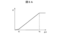
- FIG. 3A is an example of a graph showing the relationship between the rotational speed difference between the front and rear wheels and the first torque t1.
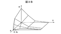
- FIG. 3B is an example of a graph showing the relationship with the accelerator opening second torque t2.
- FIG. 4 is a flowchart illustrating an example of processing executed by the control unit of the control device.
- FIG. 5 is a flowchart showing an example of processing executed by the control unit according to the second embodiment of the present invention.
- FIG. 1 is a schematic diagram showing a configuration example of a four-wheel drive vehicle according to a first embodiment of the present invention.
- the four-wheel drive vehicle 100 includes an engine 101 as a drive source, a transmission 103 as a transmission that changes the output of the engine 101, and torque transmission between the engine 101 and the transmission 103.
- the clutch 102 that can be disconnected and the output of the transmission 103 are applied to the left and right front wheels 104 (left front wheel 104L and right front wheel 104R), the driving force distribution control device 1, and the left and right rear wheels 105 (left rear wheel 105L and right rear wheel 105R).
- a driving force transmission system 110 for transmission is mounted.
- the driving force distribution control device 1 includes a driving force transmission device 2 capable of switching between a two-wheel driving state and a four-wheel driving state and capable of adjusting a transmission torque, and a control device 3 for controlling the driving force transmission device 2. Configured.
- an accelerator pedal 121, a brake pedal 122, a clutch pedal 123, and a shift lever 124 for the driver to operate are arranged in the passenger compartment of the four-wheel drive vehicle 100.
- the engine 101 is an internal combustion engine to which fuel corresponding to the depression amount of the accelerator pedal 121 is supplied, and generates a driving force for the four-wheel drive vehicle 100 to travel.
- the clutch 102 is a dry clutch that transmits torque by friction welding of a pair of rotating members, for example.
- the clutch 102 has a first disk 102a on the engine 101 side and a second disk 102b on the transmission 103 side that can rotate relative to the first disk 102a.
- the transmission 103 is a manual transmission that can change the gear ratio in a plurality of stages by a gear shift operation of the driver by the shift lever 124.
- the transmission 103 is a 5-speed transmission capable of changing the gear ratio in, for example, five stages from the first speed to the fifth speed (during forward movement). Transmission 103 can also form a neutral state in which the driving force of engine 101 is not transmitted to driving force transmission system 110.
- the driving force transmission system 110 includes a front differential device 112 that distributes torque to the left front wheel 104L and the right front wheel 104R, a first gear mechanism 111 that transmits the output of the transmission 103 to the differential case 112a of the front differential device 112, and a propeller shaft. 114, a second gear mechanism 113 that connects the differential case 112a and the propeller shaft 114, a pinion gear shaft 115 to which the torque of the propeller shaft 114 is transmitted via the driving force transmission device 2 of the driving force distribution control device 1, A rear differential device 116 that distributes the torque transmitted to the pinion gear shaft 115 to the left rear wheel 105L and the right rear wheel 105R is provided.
- the rear differential device 116 is accommodated in a differential carrier 116c.
- An oil temperature sensor 309 that detects the temperature of the differential oil that lubricates each gear of the rear differential device 116 is disposed in the differential carrier 116c.
- the oil temperature sensor 309 supplies an electric signal corresponding to the temperature of the differential oil to the control device 3.
- a ring gear 116b is provided on the outer peripheral portion of the differential case 116a of the rear differential device 116 so as not to be relatively rotatable.
- the ring gear 116b is engaged with the gear portion 115a of the pinion gear shaft 115, and transmits torque from the pinion gear shaft 115 to the differential case 116a.
- the ring gear 116b and the gear part 115a are made of hypoid gears, for example.
- the driving force transmission system 110 has drive shafts 112L and 112R respectively connected to a pair of side gears of the front differential device 112, and drive shafts 116L and 116R respectively connected to a pair of side gears of the rear differential device 116. ing.
- the drive shafts 112L and 112R transmit torque to the left front wheel 104L and the right front wheel 104R, and the drive shafts 116L and 116R transmit torque of the left rear wheel 105L and the right rear wheel 105R.
- the second gear mechanism 113, the propeller shaft 114, the pinion gear shaft 115, the rear differential device 116, and the drive shafts 116 ⁇ / b> L and 116 ⁇ / b> R are driven by the rear wheel 105 to drive the engine 101. It is an example of the driving force transmission member which transmits force.
- the torque output from the transmission 103 is always transmitted to the left front wheel 104L and the right front wheel 104R by the above configuration. Further, torque is transmitted to the left rear wheel 105L and the right rear wheel 105R according to the traveling state of the four-wheel drive vehicle 100 when necessary by the operation of the driving force transmission device 2. That is, in the four-wheel drive vehicle 100 of the present embodiment, the left front wheel 104L and the right front wheel 104R are main drive wheels, and the left rear wheel 105L and the right rear wheel 105R are auxiliary drive wheels.
- the control device 3 constituting the driving force distribution control device 1 includes a storage unit 31 having a storage element such as a ROM and a RAM, a control unit 32 including an arithmetic processing unit such as a CPU, and a current output controlled by the control unit 32. Circuit 33.
- the control device 3 is configured to function as an example of the “first control unit” and the “second control unit” according to the present invention when the control unit 32 executes the program stored in the storage unit 31. Has been. That is, the control device 3 has a first control unit and a second control unit.
- control unit 32 calculates a torque value to be transmitted to the rear wheel 105 according to the traveling state of the four-wheel drive vehicle 100 as an example of the first control means. Further, as an example of the second control unit, the control unit 32 calculates the torque calculated as the first control unit when the rotational speed of the engine 101 is equal to or higher than the first threshold value or the vehicle speed is equal to or lower than the second threshold value.
- the torque value calculated as the first control means is reduced to reduce the command torque. Value. Details of the operation of the control unit 32 will be described later.
- the current output circuit 33 supplies the driving force transmission device 2 with a current corresponding to the command torque obtained by the calculation process of the control unit 32.
- the current output circuit 33 is an inverter circuit that outputs a current supplied from a battery (not shown), for example, by adjusting a current amount by PWM (Pulse Width Modulation) control.
- PWM Pulse Width Modulation
- the control device 3 includes an engine rotation speed sensor 301 that detects the rotation speed (the number of rotations per hour) of the engine 101, and an accelerator opening that detects an accelerator opening (acceleration operation amount) corresponding to the amount of depression of the accelerator pedal 121. Detection signals of sensors 302, a clutch operation amount sensor 303 that detects a clutch operation amount corresponding to the depression amount of the clutch pedal 123, and a shift position sensor 304 that detects the position of the shift lever 124 are input.
- control device 3 is provided corresponding to each wheel of the left front wheel 104L, the right front wheel 104R, the left rear wheel 105L, and the right rear wheel 105R, and wheel speed sensors 305 to 308 for detecting the rotation speed of these wheels.
- the detection signal is input.
- control device 3 receives a detection signal from an outside air temperature sensor 310 that detects the outside air temperature.
- the outside air temperature sensor 310 is disposed inside a front bumper (not shown) of the four-wheel drive vehicle 100, for example.
- the detection signals of the sensors 301 to 310 may be directly input to the control device 3 via a signal line connected to the sensor body, or the control device 3 is communicated through an in-vehicle network such as CAN (Controller Area Network). May be entered.
- CAN Controller Area Network
- the driving force transmission device 2 transmits the torque of the engine 101 input via the propeller shaft 114 to the pinion gear shaft 115 according to the transmission torque value calculated by the control device 3 and distributes it to the rear wheel 105 side. .
- FIG. 2 is a cross-sectional view showing a configuration example of the driving force transmission device 2.
- the driving force transmission device 2 has a rotation axis O, a housing 21 as an outer rotating member, a cylindrical inner shaft 22 as an inner rotating member that can rotate relative to the housing 21, A main clutch 23 arranged between the peripheral surface and the outer peripheral surface of the inner shaft 22, a pilot clutch 24 arranged in parallel in the axial direction of the main clutch 23, and an axial pressing force acting on the pilot clutch 24
- An electromagnetic coil 25 and an armature 26 to be operated, and a cam mechanism 27 for converting the rotational force of the housing 21 transmitted by the pilot clutch 24 into a pressing force of the main clutch 23 are mainly configured.
- the housing 21 comprises a bottomed cylindrical front housing 211 and an annular rear housing 212 coupled to the front housing 211 so as to rotate integrally by screwing or the like, and is supported rotatably about the rotation axis O as a central axis. Has been.
- the housing 21 is filled with lubricating oil for lubricating between clutch plates described later.
- the front housing 211 is made of a nonmagnetic material, and a propeller shaft 114 (see FIG. 1) is connected to the bottom 211a of the front housing 211 through a cross joint, for example, so as not to be relatively rotatable.
- a plurality of spline teeth 211 b provided along the rotation axis O are formed on the inner peripheral surface of the front housing 211.
- the rear housing 212 includes a first member 212a made of a magnetic material coupled to the front housing 211, a second member 212b made of a non-magnetic material integrally joined to the inner peripheral side of the first member 212a by welding, and the like. It consists of a third member 212c made of a magnetic material integrally joined to the inner peripheral side of the two member 212b by welding or the like.
- the inner shaft 22 is supported on the inner peripheral side of the housing 21 by a ball bearing 281 and a needle roller bearing 282.
- a plurality of spline teeth 22 a provided along the rotation axis O are formed on the outer peripheral surface of the inner shaft 22.
- a plurality of spline teeth 22b are formed on the inner peripheral surface of the inner shaft 22 to connect one end of the pinion gear shaft 115 (see FIG. 1) so as not to be relatively rotatable.
- the main clutch 23 is a wet multi-plate clutch having a plurality of outer clutch plates 231 and a plurality of inner clutch plates 232 arranged alternately along the rotation axis O.
- a plurality of protrusions 231 a that fit into the plurality of spline teeth 211 b of the front housing 211 are provided on the outer peripheral portion of the outer clutch plate 231.
- a plurality of protrusions 232 a that fit into the plurality of spline teeth 22 a of the inner shaft 22 are provided on the inner peripheral portion of the inner clutch plate 232.
- the outer clutch plate 231 is not rotatable relative to the front housing 211 and is movable in the axial direction.
- the inner clutch plate 232 is not rotatable relative to the inner shaft 22 and is movable in the axial direction.
- the inner clutch plate 232 is formed with a plurality of oil holes 232b through which lubricating oil flows when the main clutch 23 is pressed in the axial direction.
- the pilot clutch 24 is a wet multi-plate clutch having a plurality of outer clutch plates 241 and a plurality of inner clutch plates 242 arranged alternately along the rotation axis O.
- a plurality of protrusions 241 a that fit into the plurality of spline teeth 211 b of the front housing 211 are provided on the outer peripheral portion of the outer clutch plate 241.
- a plurality of protrusions 242b that fit into a plurality of spline teeth 271a on an outer peripheral surface of a pilot cam 271 of the cam mechanism 27 described later are provided on the inner peripheral portion of the inner clutch plate 242.
- the outer clutch plate 241 is not rotatable relative to the front housing 211 and is movable in the axial direction. Further, the inner clutch plate 242 is not rotatable relative to the pilot cam 271 and is movable in the axial direction.
- the cam mechanism 27 includes a pilot cam 271, a main cam 273 that presses the main clutch 23 in the axial direction, and a plurality of spherical cam balls 272 disposed between the pilot cam 271 and the main cam 273. Yes.
- the main cam 273 has spline teeth 273a formed on the inner peripheral surface thereof engaged with the plurality of spline teeth 22a of the inner shaft 22, and relative rotation with the inner shaft 22 is restricted.
- a thrust needle roller bearing 284 is disposed between the pilot cam 271 and the third member 212c of the rear housing 212, and movement of the pilot cam 271 toward the rear housing 212 is restricted.
- a plurality of cam grooves 271b and 273b whose axial depth varies along the circumferential direction are formed on the opposing surfaces of the pilot cam 271 and the main cam 273.
- the cam mechanism 27 generates axial thrust that presses the main cam 273 against the main clutch 23 by the cam balls 272 rolling in these cam grooves.
- the electromagnetic coil 25 is held by an annular yoke 251 made of a magnetic material, and is disposed on the opposite side of the rear housing 212 from the pilot clutch 24.
- the yoke 251 is supported by the third member 212c by a ball bearing 283, and the outer peripheral surface thereof faces the inner peripheral surface of the first member 212a.
- the inner peripheral surface of the yoke 251 is opposed to the outer peripheral surface of the third member 212c. Excitation current is supplied to the electromagnetic coil 25 from the current output circuit 33 (see FIG. 1) of the control device 3 via the electric wire 252.
- the armature 26 is made of an annular magnetic material and is disposed so as to be movable in the axial direction facing the outer clutch plate 241 of the pilot clutch 24 so that the pilot clutch 24 is sandwiched between the armature 26 and the rear housing 212.
- a plurality of spline teeth 26 a that are fitted to the plurality of spline teeth 211 b of the front housing 211 are provided on the outer peripheral surface of the armature 26.
- the driving force transmission device 2 configured as described above, when an excitation current is supplied from the control device 3 to the electromagnetic coil 25, the yoke 251, the first member 212 a and the third member 212 c of the rear housing 212, and the pilot clutch 24. , And a magnetic flux is generated in the magnetic path G passing through the armature 26. The armature 26 is attracted toward the rear housing 212 by the magnetic force of the magnetic flux, and presses the pilot clutch 24.
- the outer clutch plate 241 and the inner clutch plate 242 of the pilot clutch 24 frictionally slide, the rotational force of the housing 21 is transmitted to the pilot cam 271 of the cam mechanism 27 via the pilot clutch 24, and the pilot cam 271 is transferred to the main cam 273.
- the main clutch 23 is pressed by the main cam 273 by the thrust of the cam mechanism 27.
- the rotational force transmitted to the pilot cam 271 due to the frictional sliding of the pilot clutch 24 changes according to the magnitude of the excitation current supplied to the electromagnetic coil 25. Accordingly, by controlling the excitation current to increase or decrease, the pressing force with which the main cam 273 presses the main clutch 23 can be changed. As a result, the torque transmitted from the housing 21 to the inner shaft 22 via the main clutch 23, that is, the propeller shaft. The transmission torque from 114 to the pinion gear shaft 115 side (see FIG. 1) can be adjusted.
- the control device 3 controls the amount of torque transmitted by the driving force transmission device 2 by adjusting the excitation current supplied to the electromagnetic coil 25.
- the control device 3 includes a normal control function for calculating a torque value to be transmitted to the rear wheel 105 based on the difference between the rotational speeds of the front and rear wheels and the acceleration operation amount of the driver, and the rotational speed of the engine 101 is lower than a predetermined value.
- a correction function for correcting the torque value calculated in the processing by the normal control function to be reduced is provided.
- the normal control function is realized by the aforementioned first control means, and the correction function is realized by the aforementioned second control means. Further, the control device 3 supplies an excitation current corresponding to the calculated or corrected torque value to the electromagnetic coil 25 of the driving force transmission device 2 by the current output circuit 33.
- the control unit 32 of the control device 3 obtains the detected value of the wheel speed sensor 305 for the left front wheel that detects the rotation speed of the left front wheel 104L and the rotation speed of the right front wheel 104R by operation according to the program stored in the storage unit 31.
- the detected value of the wheel speed sensor 306 for the right front wheel to be detected is averaged to calculate the rotational speed Vf of the front wheel 104, and the detected value of the wheel speed sensor 307 for the left rear wheel for detecting the rotational speed of the left rear wheel 105L and the right
- FIG. 3A is an example of a graph showing the relationship between the rotational speed difference ⁇ V and the first torque t1 based on the rotational speed difference ⁇ V.
- the storage unit 31 of the control device 3 stores information indicating the relationship between the rotational speed difference ⁇ V and the first torque t1, for example, in the form of a map.
- the control unit 32 refers to this information and the rotational speed difference.
- a first torque t1 corresponding to ⁇ V is obtained.
- the rotational speed difference [Delta] V is in the region of the small rotational speed difference is less than V 1, the first torque t1 is increased slowly in accordance with the increase in rotational speed difference [Delta] V.
- the first torque t1 increases rapidly than the area of the small rotational speed difference.
- the rotational speed difference ⁇ V is in the region of the V 2 or more giant slalom speed difference, the first torque t1 is a constant value.
- control unit 32 detects the accelerator opening ⁇ by the driver's operation based on the detected value of the accelerator opening sensor 302 provided corresponding to the accelerator pedal 121, and the control unit 32 detects the accelerator opening ⁇ according to the accelerator opening ⁇ . 2 Torque t2 is obtained.
- FIG. 3B is an example of a graph showing the relationship between the accelerator opening ⁇ and the second torque t2 based on the accelerator opening ⁇ .
- the vehicle speed S is added to the accelerator opening ⁇
- the graph shown in FIG. 3B shows the relationship between the accelerator opening ⁇ , the vehicle speed S, and the second torque t2.
- the storage unit 31 of the control device 3 stores information indicating the relationship between the accelerator opening ⁇ and the vehicle speed S and the second torque t2, for example, in the form of a map.
- the control unit 32 refers to this information.
- a second torque t2 corresponding to the accelerator opening ⁇ and the vehicle speed S is obtained.
- the vehicle speed S can be obtained, for example, by multiplying the average value of the rotational speed Vf of the front wheels 104 and the rotational speed Vr of the rear wheels 105 by a predetermined coefficient.
- the second torque t2 will increase relatively rapidly with an increase of the accelerator opening phi.
- the accelerator opening phi is in the region of phi 2 or more large accelerator opening, in accordance with the increase in the accelerator opening phi, further gentle second torque t2 is increased than the area of the middle accelerator opening.
- the second torque t2 is set so as to decrease as the vehicle speed S increases.
- the large driving force of the engine 101 at the time of sudden acceleration is evenly distributed between the front wheels 104 and the rear wheels 105, and the driving force is applied to the front wheels 104 side. It is possible to avoid the slip of the front wheel 104 that may occur when concentrated.
- the control device 3 also has a correction function for correcting the command torque tc obtained as described above based on the rotational speed Ve of the engine 101 and the vehicle speed S.
- this correction function when the rotation speed Ve of the engine 101 is lower than a predetermined value (first threshold value SH 1 ) and the vehicle speed S is higher than a predetermined value (second threshold value SH 2 ), the normal control function The command torque tc calculated based on the rotational speed difference ⁇ V between the front and rear wheels and the accelerator opening ⁇ is reduced.
- the driving state when the control device 3 reduces the command torque tc is that the clutch 102 is frictionally engaged by the driver's operation in a state where the driving force of the engine 101 is not transmitted to the driving force transmission system 110. This is a case where excessive torque in the deceleration direction can be generated in the driving force transmission system 110.
- the low gear (first speed; gear with the highest gear ratio) of the transmission 103 is operated by operating the shift lever 124. Assuming that the driving force transmission system 110 and the engine 101 are connected so that the driving force can be transmitted thereafter, excessive torque in the deceleration direction can be generated in the driving force transmission system 110.
- the control device 3 detects such a traveling state based on the rotational speed Ve and the vehicle speed S of the engine 101.
- the first threshold value SH 1 to be compared with the rotational speed Ve of the engine 101 can be set to, for example, 1000 ⁇ 2000rpm (revolution per minute) .
- the threshold SH 2 second to be compared with the vehicle speed S can be set to, for example, per hour 10 ⁇ 20km / h.
- the first threshold SH 1 is an engine when the four-wheel drive vehicle 100 travels at a vehicle speed set as the second threshold SH 2 in a state where the low gear of the transmission 103 is selected and the clutch 102 is frictionally engaged. A value smaller than the rotation speed of 101 is set.
- the first threshold value SH 1 may be a predetermined fixed value, or a value that varies according to vehicle speed S.
- the control unit 32 of the control device 3 When detecting that the rotational speed Ve of the engine 101 is lower than the first threshold value SH 1 and the vehicle speed S is higher than the second threshold value SH 2 , the control unit 32 of the control device 3 reduces the command torque tc.
- the current corresponding to the corrected command torque tc is supplied to the electromagnetic coil 25 of the driving force transmission device 2 as an excitation current.
- the command torque tc may be replaced with a predetermined torque value determined in advance.
- the coefficient k is, for example, 0.8 or less, more preferably 0.5 or less.
- the predetermined torque value is, for example, 80% or less, more preferably 50% or less, of the maximum torque transmission capacity by the driving force transmission device 2. Good.
- the reduction amount when the command torque tc is reduced is reduced. More specifically, based on the temperature of the differential oil detected by the oil temperature sensor 309, the reduction amount of the command torque tc due to the above correction (the difference in command torque before and after the correction) decreases the command torque tc as the temperature increases. Re-correct so that the amount is smaller.
- the higher the outside air temperature detected by the outside air temperature sensor 310 the smaller the reduction amount when the command torque tc is reduced. More specifically, based on the outside air temperature detected by the outside air temperature sensor 310, the reduction amount of the command torque tc due to the above correction is based on the outside air temperature detected by the outside air temperature sensor 310. Correct again so that becomes smaller.
- the re-correction processing of the command torque reduction amount based on the detection value of the oil temperature sensor 309 or the outside air temperature sensor 310 is, for example, a coefficient less than 1 that changes the value according to the temperature to the reduction amount of the command torque tc before re-correction.
- the value obtained by multiplying can be set as the re-corrected command torque tc.
- the control unit 3 is lower than the threshold SH 1 rotational speed Ve is the first engine 101, and between the vehicle speed S is higher than the second threshold value SH 2 continues the control for reducing corrected command torque tc , the rotational speed Ve of the engine 101 may become the first threshold value SH 1 or more, or when the vehicle speed S becomes the second threshold value SH 2 below, the processing is stopped reduction correction.
- FIG. 4 is a flowchart illustrating an example of processing executed by the control unit 32 of the control device 3.
- the control unit 32 repeatedly executes the processing shown in this flowchart every predetermined control cycle (for example, 100 ms).
- control unit 32 refers to the detection values of the wheel speed sensors 305 to 308 to calculate the rotational speed Vf of the front wheel 104 and the rotational speed Vr of the rear wheel 105 (S1). Then, based on the rotational speed Vf of the front wheel 104 and the rotational speed Vr of the rear wheel 105, a rotational speed difference ⁇ V between the front and rear wheels is calculated (S2).
- the control unit 32 refers to the torque map stored in the storage unit 31 and obtains the first torque t1 according to the rotational speed difference ⁇ V by calculation (S3).
- the control unit 32 detects the accelerator opening ⁇ based on the detection value of the accelerator opening sensor 302, and refers to the torque map stored in the storage unit 31, and the second torque t2 corresponding to the accelerator opening ⁇ . Is obtained by calculation (S4).
- the control unit 32 adds the second torque t2 to the first torque t1 to obtain the command torque tc as a torque value to be transmitted to the rear wheel 105 (S5).
- control unit 32 refers to the flag f indicating that the reduction correction process is being performed, and determines whether or not the reduction correction process is being performed (S6). If the reduction correction process is not in progress (the flag f is in an off state), the control unit 32 executes the processes in and after step S10 described later. The subsequent processing is executed. It is assumed that the flag f is initialized to the off state when the engine 101 is started.
- the control unit 32 obtains the rotational speed Ve of the engine 101 based on the detection value of the engine rotational speed sensor 301, and the rotational speed Ve of the engine 101 is the first threshold value. It is determined whether it is lower than SH 1 (S10). If the rotational speed Ve is lower than the first threshold value SH 1 (S10: Yes), the control unit 32, the vehicle speed S is determined whether the second higher than the threshold value SH 2 (S11).
- step S11 If the vehicle speed S is higher than the second threshold value SH 2 (S11: Yes), the control unit 32 turns on the flag f indicating that it is reduced correction process (S13), the command torque tc obtained in step S5 A reduction correction process is performed to reduce (S30). That is, steps S10 and S11 indicate a transition condition for shifting to the reduction correction processing mode for reducing the command torque tc.
- control unit 32 controls the current output circuit 33 according to the corrected command torque tc, and outputs a larger excitation current to the electromagnetic coil 25 of the driving force transmission device 2 as the command torque tc is higher (S31). .
- the control unit 32 obtains the rotational speed Ve of the engine 101 based on the detected value of the engine rotational speed sensor 301, and the rotational speed Ve of the engine 101 is the first. It is determined whether or not the threshold value SH is 1 or more (S20). If the rotational speed Ve is not the first threshold value SH 1 or more (S21: No), the control unit 32, the vehicle speed S is determined whether a second threshold value SH 2 or less (S21).
- the control unit 32 When the vehicle speed S is equal to or less than the second threshold value SH2 (S21: No), the control unit 32 performs a reduction correction process for reducing the command torque tc obtained in step S5 (S30), and sets the corrected command torque tc. A corresponding excitation current is output (S31).
- step S20 when the rotation speed Ve of the engine 101 is equal to or higher than the first threshold SH 1 (S20: Yes), or when the vehicle speed S is equal to or lower than the second threshold SH 2 (S21: Yes), the control unit 32
- the flag f indicating that the reduction correction process is being performed is turned off (S23), the current output circuit 33 is controlled, and the excitation coil current corresponding to the command torque tc obtained in step S5 is applied to the electromagnetic coil 25 of the driving force transmission device 2. (S31). That is, steps S20 and S21 indicate a cancel condition for canceling the reduction correction processing mode.
- the magnetic flux in the magnetic path G changes due to increase / decrease of the driving current, whereby the pressing force of the pilot clutch 24 by the armature 26 changes, and the torque transmitted via the pilot clutch 24 changes.
- the thrust generated by the cam mechanism 27 changes, the force with which the main cam 273 of the cam mechanism 27 presses the main clutch 23 fluctuates, and the transmission torque between the propeller shaft 114 and the pinion gear shaft 115 is adjusted.
- the transmission torque is adjusted with a time delay. Therefore, even if the low gear is selected by the driver's operation and the excitation current is reduced after the clutch 102 is frictionally engaged, a large torque in the deceleration direction is generated in the driving force transmission system 110.
- the transmission torque of the driving force transmission device 2 is reduced before the engine 101 and the driving force transmission system 110 are coupled so as to be able to transmit the driving force. It is possible to more reliably reduce the generated torque in the deceleration direction.
- the oil temperature sensor 309 and the outside air temperature sensor 310 are used to estimate the temperature of the lubricating oil of the driving force transmission device 2, but either the oil temperature sensor 309 or the outside air temperature sensor 310 is used.
- the reduction amount when reducing the command torque tc may be reduced based on the above.
- a temperature sensor may be provided in the yoke 251 that is a non-rotating part of the driving force transmission device 2, and the amount of reduction when the command torque tc is reduced may be reduced as the detected temperature is higher.
- the temperature of the lubricating oil in the driving force transmission device 2 may be estimated by calculation based on the rotational speed difference ⁇ V between the front and rear wheels and the excitation current supplied to the electromagnetic coil 25 of the driving force transmission device 2.
- FIG. 5 is a flowchart showing an example of processing executed by the control unit 32 according to the second embodiment of the present invention.
- steps having the same processing contents as those in the flowchart shown in FIG. 4 are denoted by the same step numbers and description thereof is omitted.
- the control unit 32 is lower than the threshold SH 1 rotational speed Ve is the first engine 101 (S10: Yes), and the vehicle speed S is second threshold SH 2 If it is higher (S11: Yes), it is determined whether the accelerator opening ⁇ based on the detected value of the accelerator opening sensor 302 is smaller than a predetermined value (third threshold value SH 3 ) (S12).
- the third threshold SH 3 can be set to a value of 1 to 20% of the accelerator opening when the accelerator is fully opened, for example.
- control unit 32 when the accelerator opening ⁇ is smaller than the third threshold value SH 3 (S12: Yes), the flag f is turned on (S13), performs the reduction correction processing (S30). That is, steps S10 to S12 show the transition conditions for shifting to the reduction correction processing mode in the present embodiment.
- the control unit 32 even if the flag f is on (reduction correction processing mode), the rotational speed Ve of the engine 101 is not the first threshold value SH 1 or more (S20: No), and the vehicle speed S is first If 2 not the threshold SH 2 or less (S21: no), determines whether the accelerator opening ⁇ is the third threshold value SH 3 or more (S22).
- steps S20 to S22 show the release conditions for releasing the reduction correction processing mode in the present embodiment.
- the command torque tc is reduced only when the accelerator opening ⁇ is less than the third threshold value SH3. Therefore, for example, when the driver depresses the accelerator pedal 121 prior to downshifting to increase the rotation speed of the engine 101, the reduction correction of the command torque tc is not executed. Therefore, the driving force of the engine 101 is distributed at a higher rate also on the rear wheel 105 side, and stable acceleration can be performed.
- Steps S10 and S11 the case of shifting to the reduction correction processing mode when the conditions of Steps S10 and S11 (see FIG. 4) or Steps S10 to S12 (see FIG. 5) are satisfied has been described.
- Other conditions may be added in addition to the conditions.
- the operation amount (depression amount) of the clutch pedal 123 detected based on the clutch operation amount sensor 303 is equal to or greater than a predetermined value, and the driving force is transmitted by the clutch 102 substantially. There may be no condition.
- it may be added as another condition that the transmission 103 is in a neutral state. In this case, the command torque tc can be reduced and corrected at a more appropriate timing.
- the front wheel 104 is the main driving wheel and the rear wheel 105 is the auxiliary driving wheel has been described.
- the front wheel 104 is the auxiliary driving wheel and the rear wheel 105 is the auxiliary driving wheel. It may be a main drive wheel.
- the command torque tc is calculated by adding the second torque t2 based on the accelerator opening ⁇ to the first torque t1 based on the rotational speed difference ⁇ V between the front wheels 104 and the rear wheels 105.
- the command torque tc may be calculated based on at least the first torque t1. That is, the control unit 32 of the control device 3 may calculate the command torque tc based only on the first torque t1 as the first control means.
- the rotation speed Ve of the engine 101 is obtained based on the detection value of the engine rotation speed sensor 301.
- the present invention is not limited to this.
- the gear based on the vehicle speed S and the detection value of the shift position sensor 304 The rotational speed Ve of the engine 101 may be obtained based on the gear ratio of the stage.
- the four-wheel drive vehicle 100 is a so-called MT vehicle equipped with a manual transmission (manual transmission)
- the vehicle can be downshifted by a driver's operation.
- the present invention may be applied to a so-called AT vehicle equipped with an automatic transmission (automatic transmission).
Landscapes
- Engineering & Computer Science (AREA)
- Transportation (AREA)
- Mechanical Engineering (AREA)
- Chemical & Material Sciences (AREA)
- Combustion & Propulsion (AREA)
- Automation & Control Theory (AREA)
- Arrangement And Driving Of Transmission Devices (AREA)
Abstract
Description
図1は、本発明の第1の実施の形態に係る四輪駆動車の構成例を示す概略図である。図1に示すように、この四輪駆動車100は、駆動源としてのエンジン101と、エンジン101の出力を変速する変速装置としてのトランスミッション103と、エンジン101とトランスミッション103との間のトルク伝達を遮断可能なクラッチ102と、トランスミッション103の出力を左右の前輪104(左前輪104L及び右前輪104R)及び駆動力配分制御装置1ならびに左右の後輪105(左後輪105L及び右後輪105R)に伝達する駆動力伝達系110と、を搭載している。駆動力配分制御装置1は、二輪駆動状態と四輪駆動状態とを切替可能であり、伝達トルクを調節可能な駆動力伝達装置2と、駆動力伝達装置2を制御する制御装置3とを備えて構成されている。
駆動力伝達系110は、左前輪104L及び右前輪104Rにトルクを配分するフロントデファレンシャル装置112と、トランスミッション103の出力をフロントデファレンシャル装置112のデフケース112aに伝達する第1のギヤ機構111と、プロペラシャフト114と、デフケース112aとプロペラシャフト114とを連結する第2のギヤ機構113と、駆動力配分制御装置1の駆動力伝達装置2を介してプロペラシャフト114のトルクが伝達されるピニオンギヤシャフト115と、ピニオンギヤシャフト115に伝達されたトルクを左後輪105L及び右後輪105Rに配分するリヤデファレンシャル装置116とを備えている。
駆動力配分制御装置1を構成する制御装置3は、ROMやRAM等の記憶素子を有する記憶部31と、CPU等の演算処理装置からなる制御部32と、制御部32によって制御される電流出力回路33とを備えている。制御装置3は、制御部32が記憶部31に記憶されたプログラムを実行することにより、本発明に係る「第1の制御手段」及び「第2の制御手段」の一例として機能するように構成されている。つまり、制御装置3は、第1の制御手段と第2の制御手段とを有している。
駆動力伝達装置2は、制御装置3が演算により求めた伝達トルク値に応じて、プロペラシャフト114を介して入力されたエンジン101のトルクをピニオンギヤシャフト115に伝達し、後輪105側に配分する。
制御装置3は、電磁コイル25に供給する励磁電流を調節することにより、駆動力伝達装置2によるトルクの伝達量を制御する。制御装置3は、前後輪の回転速度の差、及び運転者の加速操作量に基づいて後輪105に伝達すべきトルク値を算出する通常制御機能と、エンジン101の回転速度が所定値よりも低く、かつ車速が所定値よりも高い場合に、通常制御機能による処理において算出したトルク値を低減するように補正する補正機能とを有している。通常制御機能は前述の第1の制御手段によって実現され、補正機能は前述の第2の制御手段によって実現される。また、制御装置3は、算出又は補正されたトルク値に応じた励磁電流を、電流出力回路33によって駆動力伝達装置2の電磁コイル25に供給する。
制御装置3の制御部32は、記憶部31に記憶されたプログラムに従った動作により、左前輪104Lの回転速度を検出する左前輪の車輪速センサ305の検出値と右前輪104Rの回転速度を検出する右前輪の車輪速センサ306の検出値とを平均して前輪104の回転速度Vfを算出し、左後輪105Lの回転速度を検出する左後輪の車輪速センサ307の検出値と右後輪105Rの回転速度を検出する右後輪の車輪速センサ308の検出値とを平均して後輪105の回転速度Vrを算出する。そして、前輪104の回転速度Vfから後輪105の回転速度Vrを減算して前後輪の回転速差ΔV(ΔV=Vf-Vr)を得る。
制御装置3はまた、上記のように求めた指令トルクtcをエンジン101の回転速度Ve及び車速Sに基づいて補正する補正機能を有している。この補正機能では、エンジン101の回転速度Veが所定値(第1の閾値SH1)よりも低く、かつ車速Sが所定値(第2の閾値SH2)よりも高い場合に、通常制御機能によって前後輪の回転速差ΔV及びアクセル開度φに基づいて算出した指令トルクtcを低減する。
図4は、制御装置3の制御部32が実行する処理の一例を示すフローチャートである。制御部32は、このフローチャートに示す処理を所定の制御周期(例えば100ms)ごとに繰り返し実行する。
以上説明した第1の実施の形態によれば、エンジン101の回転速度Veが第1の閾値SH1よりも低く、かつ車速Sが第2の閾値SH2よりも高い場合に、前後輪の回転速差ΔV及びアクセル開度φに基づいて算出した指令トルクtcが低減される。このため、例えば運転者がローギヤを選択し、クラッチ102を急激に繋いだ場合に駆動力伝達系110に発生する減速方向のトルクを低減することが可能となる。これにより、プロペラシャフト114やリヤデファレンシャル装置116等の後輪105に駆動力を伝達する駆動力伝達部材に発生し得る減速方向のトルクの最大値を低減することが可能となる。
次に、本発明の第2の実施の形態について、図5を参照して説明する。本実施の形態では、四輪駆動車100の構成は第1の実施の形態と共通であるが、制御装置3の制御部32が実行する処理の内容が第1の実施の形態とは異なる。
以上説明した第2の実施の形態によれば、第1の実施の形態の作用及び効果に加え、アクセル開度φが第3の閾値SH3未満の場合に限って指令トルクtcが低減されるので、例えば運転者がシフトダウンに先駆けてアクセルペダル121を踏み込み操作し、エンジン101の回転速度を高めようとしている場合には、指令トルクtcの低減補正が実行されない。したがって、後輪105側にもエンジン101の駆動力がより高い割合で配分され、安定した加速を行うことが可能となる。
以上、本発明の駆動力配分制御装置、及び四輪駆動車を上記実施の形態に基づいて説明したが、本発明はこれらの実施の形態に限定されるものではなく、その要旨を逸脱しない範囲で種々の態様において実施することが可能である。
Claims (8)
- 駆動力を発生するエンジン、前記エンジンの出力を変速する変速装置、前記エンジンと前記変速装置との間のトルク伝達を遮断可能なクラッチ、及び前記変速装置の出力を前輪又は後輪の一方の主駆動輪と他方の補助駆動輪とに伝達することが可能な駆動力伝達系を有する四輪駆動車に搭載され、
前記補助駆動輪に伝達すべき指令トルク値を算出する制御装置と、
前記指令トルク値に応じたトルクを前記補助駆動輪に伝達する駆動力伝達装置とを備え、
前記制御装置は、
走行状態に応じて前記補助駆動輪に伝達すべきトルク値を算出する第1の制御手段と、
前記エンジンの回転速度が第1の閾値以上、又は、車速が第2の閾値以下の場合に、前記第1の制御手段が算出したトルク値を前記指令トルク値とし、前記エンジンの回転速度が第1の閾値よりも低く、かつ車速が第2の閾値よりも高い場合に前記第1の制御手段が算出したトルク値を低減して前記指令トルク値とする、第2の制御手段とを有する
駆動力配分制御装置。 - 前記第2の制御手段は、前記エンジンの回転速度が第1の閾値よりも低く、車速が第2の閾値よりも高く、かつ運転者による前記加速操作量が第3の閾値よりも小さい場合に、前記第1の制御手段が算出したトルク値を低減する
請求項1に記載の駆動力配分制御装置。 - 前記前輪は左前輪と右前輪とを含み、
前記後輪は左後輪と右後輪とを含み、
前記左前輪の回転速度を検出する左前輪の車輪速センサと、
前記右前輪の回転速度を検出する右前輪の車輪速センサと、
前記左後輪の回転速度を検出する左後輪の車輪速センサと、
前記右後輪の回転速度を検出する右後輪の車輪速センサと、
を備え、
前記左前輪の回転速度の検出値と前記右前輪の回転速度の検出値の平均から前記前輪の回転速度を算出し、
前記左後輪の回転速度の検出値と前記右後輪の回転速度の検出値の平均から前記後輪の回転速度を算出し、
前記前輪の回転速度と前記後輪の回転速度とを減算した回転速差を算出し、
前記第1の制御手段は、少なくとも前記回転速差に基づいて、前記補助駆動輪に伝達すべきトルク値を算出する、
請求項1または2に記載の駆動力配分制御装置。 - 前記主駆動輪が前輪であり、前記補助駆動輪が後輪である四輪駆動車に搭載される
請求項1乃至3の何れか1項に記載の駆動力配分制御装置。 - 前記第1の閾値は1000~2000rpmであり、前記第2の閾値は時速10~20km/hである請求項1乃至4の何れか1項に記載の駆動力配分制御装置。
- 前記駆動力伝達系は、前記駆動力伝達装置と前記補助駆動輪との間に配置されたディファレンシャル装置を含み、
前記制御装置は、前記ディファレンシャル装置を収容するデフキャリア内のデフオイルの温度が高いほど前記トルク値の低減量を小さくする
請求項1乃至5の何れか1項に記載の駆動力配分制御装置。 - 前記制御装置は、外気温が高いほど前記トルク値の低減量を小さくする
請求項1乃至5の何れか1項に記載の駆動力配分制御装置。 - 駆動力を発生するエンジンと、
前記エンジンの出力を変速する変速装置と、
前記エンジンと前記変速装置との間のトルク伝達を遮断可能なクラッチと、
前記変速装置の出力を前輪又は後輪の一方の主駆動輪と他方の補助駆動輪とに伝達することが可能な駆動力伝達系と、
請求項1乃至7の何れか1項に記載の駆動力配分制御装置とを備える
四輪駆動車。
Priority Applications (4)
| Application Number | Priority Date | Filing Date | Title |
|---|---|---|---|
| JP2013507403A JP5559421B2 (ja) | 2011-03-31 | 2012-03-19 | 駆動力配分制御装置及び四輪駆動車 |
| DE112012001518.5T DE112012001518T5 (de) | 2011-03-31 | 2012-03-19 | Antriebskraftverteilungssteuergerät und Fahrzeug mit Vierradantrieb |
| US14/008,803 US9020723B2 (en) | 2011-03-31 | 2012-03-19 | Driving force distribution controller and four-wheel drive vehicle |
| CN201280016007.1A CN103442922B (zh) | 2011-03-31 | 2012-03-19 | 驱动力分配控制装置和四轮驱动车 |
Applications Claiming Priority (2)
| Application Number | Priority Date | Filing Date | Title |
|---|---|---|---|
| JP2011-080042 | 2011-03-31 | ||
| JP2011080042 | 2011-03-31 |
Publications (1)
| Publication Number | Publication Date |
|---|---|
| WO2012132996A1 true WO2012132996A1 (ja) | 2012-10-04 |
Family
ID=46930728
Family Applications (1)
| Application Number | Title | Priority Date | Filing Date |
|---|---|---|---|
| PCT/JP2012/057020 Ceased WO2012132996A1 (ja) | 2011-03-31 | 2012-03-19 | 駆動力配分制御装置及び四輪駆動車 |
Country Status (5)
| Country | Link |
|---|---|
| US (1) | US9020723B2 (ja) |
| JP (1) | JP5559421B2 (ja) |
| CN (1) | CN103442922B (ja) |
| DE (1) | DE112012001518T5 (ja) |
| WO (1) | WO2012132996A1 (ja) |
Cited By (2)
| Publication number | Priority date | Publication date | Assignee | Title |
|---|---|---|---|---|
| JP2015013564A (ja) * | 2013-07-04 | 2015-01-22 | 株式会社ジェイテクト | 駆動力伝達装置 |
| FR3014775A1 (fr) * | 2013-12-12 | 2015-06-19 | Renault Sa | Systeme de commande d'un coupleur entre train avant et train arriere d'un vehicule automobile et procede de commande associe |
Families Citing this family (19)
| Publication number | Priority date | Publication date | Assignee | Title |
|---|---|---|---|---|
| GB2488529A (en) * | 2011-02-18 | 2012-09-05 | Land Rover Uk Ltd | Vehicle with power transfer clutch actuator which reduces mode chattering |
| JP5849770B2 (ja) * | 2012-02-29 | 2016-02-03 | 株式会社ジェイテクト | 四輪駆動車、及び四輪駆動車の制御装置 |
| JP5841584B2 (ja) * | 2013-12-06 | 2016-01-13 | 富士重工業株式会社 | パワートレインの制御装置 |
| EP3112200B1 (en) * | 2014-02-27 | 2018-05-02 | Nissan Motor Co., Ltd | Clutch control device for 4-wheel drive vehicle |
| US9688141B2 (en) | 2014-02-27 | 2017-06-27 | Nissan Motor Co., Ltd. | Clutch control device for four-wheel drive vehicle |
| DE102014016450B3 (de) | 2014-11-06 | 2016-02-25 | Audi Ag | Verfahren zum Betreiben eines Mehrachsantriebsstrangs für ein Kraftfahrzeug sowie entsprechender Mehrachsantriebsstrang |
| JP6380055B2 (ja) * | 2014-11-28 | 2018-08-29 | 株式会社ジェイテクト | 四輪駆動車の制御装置 |
| CN107208716B (zh) * | 2015-02-17 | 2019-10-01 | 本田技研工业株式会社 | 动力分配装置的油压控制装置 |
| DE102015113080B4 (de) | 2015-08-07 | 2018-02-22 | Gkn Automotive Ltd. | Verfahren zum Betrieb eines Antriebsstranges eines Fahrzeugs mit einem Kupplungsaggregat zur Verteilung von Drehmoment und Fahrzeug |
| JP6380444B2 (ja) * | 2016-03-29 | 2018-08-29 | マツダ株式会社 | ハイブリッド車及び車両 |
| JP6786986B2 (ja) * | 2016-09-16 | 2020-11-18 | 株式会社ジェイテクト | 四輪駆動車の制御装置 |
| WO2018110348A1 (ja) * | 2016-12-13 | 2018-06-21 | 本田技研工業株式会社 | トルク配分装置の制御装置 |
| JP6642517B2 (ja) * | 2017-05-16 | 2020-02-05 | トヨタ自動車株式会社 | 駆動力制御装置 |
| US10538245B2 (en) * | 2017-11-10 | 2020-01-21 | International Truck Intellectual Property Company, Llc | Multiple range independently disconnecting smart axle |
| JP7404824B2 (ja) * | 2019-11-29 | 2023-12-26 | 株式会社ジェイテクト | 駆動力伝達装置及び駆動力伝達装置の制御方法 |
| CN113715597B (zh) * | 2020-05-21 | 2023-02-03 | 华为数字能源技术有限公司 | 动力驱动系统及车辆 |
| BR102020020462A2 (pt) * | 2020-10-05 | 2022-04-19 | Fras Le S A | Veículo comercial automotor, eixo auxiliar para veículo comercial automotor, dispositivo e método de acoplamento e/ou desacoplamento de eixo de veículo comercial automotor |
| KR102895259B1 (ko) * | 2020-10-12 | 2025-12-03 | 현대자동차주식회사 | 차량의 구동력 제어 방법 |
| CN114094899A (zh) * | 2021-11-18 | 2022-02-25 | 苏州臻迪智能科技有限公司 | 一种电机控制方法、装置及系统 |
Citations (4)
| Publication number | Priority date | Publication date | Assignee | Title |
|---|---|---|---|---|
| JPS63180521A (ja) * | 1987-01-21 | 1988-07-25 | Nippon Denso Co Ltd | 4輪駆動車の駆動力可変分配装置 |
| JP2004189228A (ja) * | 2004-02-02 | 2004-07-08 | Toyota Motor Corp | 車両用トルク配分クラッチの制御装置 |
| JP2004262321A (ja) * | 2003-02-28 | 2004-09-24 | Toyoda Mach Works Ltd | 4輪駆動車のトルク配分制御装置 |
| JP2004306802A (ja) * | 2003-04-08 | 2004-11-04 | Toyota Motor Corp | 車両用駆動力配分装置の制御装置 |
Family Cites Families (4)
| Publication number | Priority date | Publication date | Assignee | Title |
|---|---|---|---|---|
| JPH0825398B2 (ja) * | 1986-07-10 | 1996-03-13 | マツダ株式会社 | 4輪駆動車のトルク制御装置 |
| JP3823072B2 (ja) | 2002-06-19 | 2006-09-20 | 株式会社ジェイテクト | 前後輪駆動車 |
| JP3582521B2 (ja) * | 2002-08-13 | 2004-10-27 | 日産自動車株式会社 | 4輪駆動車両の駆動力制御装置 |
| JP4120335B2 (ja) * | 2002-09-26 | 2008-07-16 | 日産自動車株式会社 | 4輪駆動車の駆動力配分制御装置 |
-
2012
- 2012-03-19 DE DE112012001518.5T patent/DE112012001518T5/de not_active Withdrawn
- 2012-03-19 US US14/008,803 patent/US9020723B2/en active Active
- 2012-03-19 WO PCT/JP2012/057020 patent/WO2012132996A1/ja not_active Ceased
- 2012-03-19 CN CN201280016007.1A patent/CN103442922B/zh active Active
- 2012-03-19 JP JP2013507403A patent/JP5559421B2/ja active Active
Patent Citations (4)
| Publication number | Priority date | Publication date | Assignee | Title |
|---|---|---|---|---|
| JPS63180521A (ja) * | 1987-01-21 | 1988-07-25 | Nippon Denso Co Ltd | 4輪駆動車の駆動力可変分配装置 |
| JP2004262321A (ja) * | 2003-02-28 | 2004-09-24 | Toyoda Mach Works Ltd | 4輪駆動車のトルク配分制御装置 |
| JP2004306802A (ja) * | 2003-04-08 | 2004-11-04 | Toyota Motor Corp | 車両用駆動力配分装置の制御装置 |
| JP2004189228A (ja) * | 2004-02-02 | 2004-07-08 | Toyota Motor Corp | 車両用トルク配分クラッチの制御装置 |
Cited By (2)
| Publication number | Priority date | Publication date | Assignee | Title |
|---|---|---|---|---|
| JP2015013564A (ja) * | 2013-07-04 | 2015-01-22 | 株式会社ジェイテクト | 駆動力伝達装置 |
| FR3014775A1 (fr) * | 2013-12-12 | 2015-06-19 | Renault Sa | Systeme de commande d'un coupleur entre train avant et train arriere d'un vehicule automobile et procede de commande associe |
Also Published As
| Publication number | Publication date |
|---|---|
| DE112012001518T5 (de) | 2014-01-09 |
| US20140129105A1 (en) | 2014-05-08 |
| JPWO2012132996A1 (ja) | 2014-07-28 |
| CN103442922A (zh) | 2013-12-11 |
| US9020723B2 (en) | 2015-04-28 |
| CN103442922B (zh) | 2016-03-30 |
| JP5559421B2 (ja) | 2014-07-23 |
Similar Documents
| Publication | Publication Date | Title |
|---|---|---|
| JP5559421B2 (ja) | 駆動力配分制御装置及び四輪駆動車 | |
| JP5808601B2 (ja) | 駆動力配分制御装置及び四輪駆動車 | |
| JP4267495B2 (ja) | 4輪駆動車両の駆動力制御方法 | |
| CN105644361B (zh) | 四轮驱动车的控制装置 | |
| US10245950B2 (en) | Control device of vehicular four-wheel drive system | |
| JP5827059B2 (ja) | 路面摩擦係数推定装置、駆動力配分制御装置、及び四輪駆動車 | |
| JP4554252B2 (ja) | 4輪駆動車両の制御方法 | |
| JP6216666B2 (ja) | 駆動力配分制御装置 | |
| JP4476742B2 (ja) | 4輪駆動車両の制御方法 | |
| JP2020192962A (ja) | 四輪駆動車 | |
| JP6786986B2 (ja) | 四輪駆動車の制御装置 | |
| EP1627763B1 (en) | Control method for four-wheel drive vehicle | |
| JP4417203B2 (ja) | 4輪駆動車両の駆動力制御方法 | |
| JP3570214B2 (ja) | 車両用摩擦係合装置の温度推定装置 | |
| JP2005289161A (ja) | 4輪駆動車両の駆動力制御方法 | |
| JP2010023734A (ja) | 前後輪駆動車両の駆動力配分制御装置 | |
| JP4155378B2 (ja) | 4輪駆動車の駆動制御装置 | |
| EP1582392A2 (en) | Control method for four-wheel drive vehicle | |
| JP4298564B2 (ja) | 4輪駆動車両の駆動力制御方法 | |
| JP2004314762A (ja) | 車両用摩擦係合装置の制御装置 | |
| JP4923126B2 (ja) | 4輪駆動車両の制御方法 | |
| JP2005289162A5 (ja) | ||
| JP2014080089A (ja) | 4輪駆動車両のトラクション制御装置 |
Legal Events
| Date | Code | Title | Description |
|---|---|---|---|
| WWE | Wipo information: entry into national phase |
Ref document number: 201280016007.1 Country of ref document: CN |
|
| 121 | Ep: the epo has been informed by wipo that ep was designated in this application |
Ref document number: 12765463 Country of ref document: EP Kind code of ref document: A1 |
|
| ENP | Entry into the national phase |
Ref document number: 2013507403 Country of ref document: JP Kind code of ref document: A |
|
| WWE | Wipo information: entry into national phase |
Ref document number: 112012001518 Country of ref document: DE Ref document number: 1120120015185 Country of ref document: DE |
|
| WWE | Wipo information: entry into national phase |
Ref document number: 14008803 Country of ref document: US |
|
| 122 | Ep: pct application non-entry in european phase |
Ref document number: 12765463 Country of ref document: EP Kind code of ref document: A1 |