WO2012132926A1 - 熱伝導性シートの製造方法および熱伝導性シート - Google Patents
熱伝導性シートの製造方法および熱伝導性シート Download PDFInfo
- Publication number
- WO2012132926A1 WO2012132926A1 PCT/JP2012/056682 JP2012056682W WO2012132926A1 WO 2012132926 A1 WO2012132926 A1 WO 2012132926A1 JP 2012056682 W JP2012056682 W JP 2012056682W WO 2012132926 A1 WO2012132926 A1 WO 2012132926A1
- Authority
- WO
- WIPO (PCT)
- Prior art keywords
- resin
- conductive sheet
- sheet
- thermally conductive
- resin composition
- Prior art date
- Legal status (The legal status is an assumption and is not a legal conclusion. Google has not performed a legal analysis and makes no representation as to the accuracy of the status listed.)
- Ceased
Links
Images
Classifications
-
- B—PERFORMING OPERATIONS; TRANSPORTING
- B29—WORKING OF PLASTICS; WORKING OF SUBSTANCES IN A PLASTIC STATE IN GENERAL
- B29C—SHAPING OR JOINING OF PLASTICS; SHAPING OF MATERIAL IN A PLASTIC STATE, NOT OTHERWISE PROVIDED FOR; AFTER-TREATMENT OF THE SHAPED PRODUCTS, e.g. REPAIRING
- B29C51/00—Shaping by thermoforming, i.e. shaping sheets or sheet like preforms after heating, e.g. shaping sheets in matched moulds or by deep-drawing; Apparatus therefor
- B29C51/18—Thermoforming apparatus
-
- H—ELECTRICITY
- H05—ELECTRIC TECHNIQUES NOT OTHERWISE PROVIDED FOR
- H05K—PRINTED CIRCUITS; CASINGS OR CONSTRUCTIONAL DETAILS OF ELECTRIC APPARATUS; MANUFACTURE OF ASSEMBLAGES OF ELECTRICAL COMPONENTS
- H05K7/00—Constructional details common to different types of electric apparatus
- H05K7/20—Modifications to facilitate cooling, ventilating, or heating
-
- C—CHEMISTRY; METALLURGY
- C09—DYES; PAINTS; POLISHES; NATURAL RESINS; ADHESIVES; COMPOSITIONS NOT OTHERWISE PROVIDED FOR; APPLICATIONS OF MATERIALS NOT OTHERWISE PROVIDED FOR
- C09K—MATERIALS FOR MISCELLANEOUS APPLICATIONS, NOT PROVIDED FOR ELSEWHERE
- C09K5/00—Heat-transfer, heat-exchange or heat-storage materials, e.g. refrigerants; Materials for the production of heat or cold by chemical reactions other than by combustion
- C09K5/08—Materials not undergoing a change of physical state when used
-
- C—CHEMISTRY; METALLURGY
- C09—DYES; PAINTS; POLISHES; NATURAL RESINS; ADHESIVES; COMPOSITIONS NOT OTHERWISE PROVIDED FOR; APPLICATIONS OF MATERIALS NOT OTHERWISE PROVIDED FOR
- C09K—MATERIALS FOR MISCELLANEOUS APPLICATIONS, NOT PROVIDED FOR ELSEWHERE
- C09K5/00—Heat-transfer, heat-exchange or heat-storage materials, e.g. refrigerants; Materials for the production of heat or cold by chemical reactions other than by combustion
- C09K5/08—Materials not undergoing a change of physical state when used
- C09K5/14—Solid materials, e.g. powdery or granular
-
- H—ELECTRICITY
- H05—ELECTRIC TECHNIQUES NOT OTHERWISE PROVIDED FOR
- H05K—PRINTED CIRCUITS; CASINGS OR CONSTRUCTIONAL DETAILS OF ELECTRIC APPARATUS; MANUFACTURE OF ASSEMBLAGES OF ELECTRICAL COMPONENTS
- H05K7/00—Constructional details common to different types of electric apparatus
- H05K7/20—Modifications to facilitate cooling, ventilating, or heating
- H05K7/2039—Modifications to facilitate cooling, ventilating, or heating characterised by the heat transfer by conduction from the heat generating element to a dissipating body
- H05K7/20436—Inner thermal coupling elements in heat dissipating housings, e.g. protrusions or depressions integrally formed in the housing
- H05K7/20445—Inner thermal coupling elements in heat dissipating housings, e.g. protrusions or depressions integrally formed in the housing the coupling element being an additional piece, e.g. thermal standoff
- H05K7/20472—Sheet interfaces
- H05K7/20481—Sheet interfaces characterised by the material composition exhibiting specific thermal properties
-
- H—ELECTRICITY
- H10—SEMICONDUCTOR DEVICES; ELECTRIC SOLID-STATE DEVICES NOT OTHERWISE PROVIDED FOR
- H10W—GENERIC PACKAGES, INTERCONNECTIONS, CONNECTORS OR OTHER CONSTRUCTIONAL DETAILS OF DEVICES COVERED BY CLASS H10
- H10W40/00—Arrangements for thermal protection or thermal control
- H10W40/10—Arrangements for heating
-
- H—ELECTRICITY
- H10—SEMICONDUCTOR DEVICES; ELECTRIC SOLID-STATE DEVICES NOT OTHERWISE PROVIDED FOR
- H10W—GENERIC PACKAGES, INTERCONNECTIONS, CONNECTORS OR OTHER CONSTRUCTIONAL DETAILS OF DEVICES COVERED BY CLASS H10
- H10W40/00—Arrangements for thermal protection or thermal control
- H10W40/20—Arrangements for cooling
- H10W40/25—Arrangements for cooling characterised by their materials
- H10W40/251—Organics
-
- B—PERFORMING OPERATIONS; TRANSPORTING
- B29—WORKING OF PLASTICS; WORKING OF SUBSTANCES IN A PLASTIC STATE IN GENERAL
- B29C—SHAPING OR JOINING OF PLASTICS; SHAPING OF MATERIAL IN A PLASTIC STATE, NOT OTHERWISE PROVIDED FOR; AFTER-TREATMENT OF THE SHAPED PRODUCTS, e.g. REPAIRING
- B29C43/00—Compression moulding, i.e. applying external pressure to flow the moulding material; Apparatus therefor
- B29C43/32—Component parts, details or accessories; Auxiliary operations
- B29C43/56—Compression moulding under special conditions, e.g. vacuum
- B29C2043/561—Compression moulding under special conditions, e.g. vacuum under vacuum conditions
Definitions
- the present invention relates to a method for producing a heat conductive sheet and a heat conductive sheet, and more specifically, a method for producing a heat conductive sheet used in power electronics technology, and a heat conductivity obtained by the method for producing the heat conductive sheet. Regarding the sheet.
- the boron nitride powder is oriented so that its long axis direction (direction orthogonal to the plate thickness of the boron nitride powder) is along the thickness direction of the sheet.
- the thermal conductivity in the thickness direction of the conductive sheet is improved.
- the thermal conductive sheet may be required to have high thermal conductivity in the orthogonal direction (plane direction) orthogonal to the thickness direction depending on the application and purpose.
- the heat conductive sheet of Patent Document 1 since the long axis direction of the boron nitride powder is orthogonal (crossed) to the surface direction, the heat conductivity in the surface direction is insufficient. There is a bug.
- such a heat conductive sheet tends to generate voids therein, and the voids may cause various electrical characteristics such as a decrease in thermal conductivity and a decrease in dielectric strength (dielectric breakdown voltage). .
- An object of the present invention is to provide a thermal conductive sheet having excellent thermal conductivity in the surface direction and having reduced internal voids, and a method for producing the same.
- the manufacturing method of the heat conductive sheet of this invention is a manufacturing method of the heat conductive sheet whose thermal conductivity of the orthogonal direction with respect to the thickness direction is 10 W / m * K or more, Comprising: Resin and a heat conductive inorganic particle are contained.
- the heat conductive inorganic particles can be dispersed in a form oriented in a predetermined direction, and the viscosity is in that state. Since it is increased, voids in the sheet can be reduced.
- the thermal conductivity in the surface direction perpendicular to the thickness direction is excellent, and further, the thermal conductivity is excellent in various electrical characteristics such as dielectric strength (dielectric breakdown voltage). Sheet can be produced.
- the sheet forming step includes a melting step in which the resin composition is hot-pressed under heating and pressurizing conditions in which the resin is thermally melted, and after the melting step. It is preferable to provide a holding step of lowering the temperature to a temperature at which the resin does not substantially flow and holding the resin in a pressurized state until the temperature is reached.
- the resin composition that has been heat-melted in the melting step lowers the temperature to a temperature at which the resin does not substantially flow in the holding step, and is in a pressurized state until reaching the temperature. Since it is hold
- the resin in the melting step, the resin is hot-pressed so that the viscosity of the resin is less than 5000 mPa ⁇ s, and in the holding step, the viscosity of the resin is 5000 mPa ⁇ s or more. It is preferable to hold the sheet until.
- the sheet that has been hot-pressed so that the viscosity of the resin is less than 5000 mPa ⁇ s is held in the holding step until it reaches 5000 mPa ⁇ s or more. Therefore, the orientation of the thermally conductive inorganic particles can be further improved and the voids in the sheet can be reduced.
- the said heat conductive inorganic particle is a scaly particle
- the said resin composition is the said heat
- the scaly heat conductive inorganic particles having an average primary particle diameter of 10 ⁇ m or more are contained in the resin composition in a proportion of 40% by volume or more. High thermal conductivity can be ensured.
- the heat conductive sheet of the present invention is obtained by the above-described method for producing a heat conductive sheet, and is characterized in that the porosity is 30% by volume or less.
- Such a heat conductive sheet is obtained by the above method, and has a porosity of 30% by volume or less, so that it has excellent thermal conductivity in the plane direction perpendicular to the thickness direction, and has a dielectric strength (dielectric breakdown voltage). ) And other various electrical characteristics.
- the heat conductive sheet of this invention while being excellent in the heat conductivity of the surface direction orthogonal to the thickness direction, the heat conductive sheet excellent in various electrical characteristics, such as a dielectric strength (dielectric breakdown voltage), can be obtained. .
- the process of defoaming etc. is not required in order to reduce the space
- the thermal conductive sheet of the present invention is excellent in thermal conductivity in the plane direction perpendicular to the thickness direction, and as a thermal conductive sheet excellent in various electric characteristics such as dielectric strength (dielectric breakdown voltage), and is used for various heat dissipation applications. be able to.
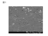
- the image processing figure of the SEM photograph of the cross section along the thickness direction of the heat conductive sheet of Example 1 is shown.
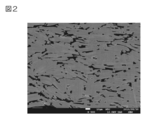
- the image processing figure of the SEM photograph of the cross section along the thickness direction of the heat conductive sheet of the comparative example 1 is shown.
- a resin composition containing a resin and heat conductive inorganic particles is prepared (preparation step).
- the resin is particularly limited as long as it can disperse the thermally conductive inorganic particles, that is, a dispersion medium (matrix) in which the thermally conductive inorganic particles are dispersed, and causes a change in viscosity in the sheet forming process described later.
- a dispersion medium matrix
- resin components such as a thermosetting resin component and a thermoplastic resin component, are mentioned.
- thermosetting resin component examples include epoxy resin, thermosetting polyimide, phenol resin, urea resin, melamine resin, unsaturated polyester resin, diallyl phthalate resin, silicone resin, thermosetting urethane resin, and the like.
- thermoplastic resin component examples include polyolefin (for example, polyethylene, polypropylene, ethylene-propylene copolymer, etc.), acrylic resin (for example, polymethyl methacrylate, etc.), polyvinyl acetate, ethylene-vinyl acetate copolymer, Polyvinyl chloride, polystyrene, polyacrylonitrile, polyamide (nylon (registered trademark)), polycarbonate, polyacetal, polyethylene terephthalate, polyphenylene oxide, polyphenylene sulfide, polysulfone, polyethersulfone, polyetheretherketone, polyallylsulfone, thermoplastic polyimide, Thermoplastic urethane resin, polyaminobismaleimide, polyamideimide, polyetherimide, bismaleimide triazine resin, polymethylpentene, Resin, liquid crystal polymer, an olefin - vinyl alcohol copolymer, ionomer, polyarylate, acryl
- These resins can be used alone or in combination of two or more.
- the thermosetting resin component is preferably an epoxy resin
- the thermoplastic resin component is preferably a polyolefin.
- the epoxy resin is in a liquid, semi-solid or solid form at normal temperature.
- epoxy resin for example, bisphenol type epoxy resin (for example, bisphenol A type epoxy resin, bisphenol F type epoxy resin, bisphenol S type epoxy resin, water-added bisphenol A type epoxy resin, dimer acid modified bisphenol type) Epoxy resin), novolak epoxy resin (eg, phenol novolac epoxy resin, cresol novolac epoxy resin, biphenyl epoxy resin), naphthalene epoxy resin, fluorene epoxy resin (eg, bisarylfluorene epoxy resin, etc.) ), Aromatic epoxy resins such as triphenylmethane type epoxy resin (for example, trishydroxyphenylmethane type epoxy resin), for example, triepoxypropyl isocyanur Nitrogen-containing ring epoxy resins such as benzoic acid (triglycidyl isocyanurate) and hydantoin epoxy resins, for example, aliphatic epoxy resins, alicyclic epoxy resins (for example, dicyclocyclic epoxy resins), glycidyl
- epoxy resins can be used alone or in combination of two or more.
- a semi-solid epoxy resin is used alone, more preferably a semi-solid aromatic epoxy resin is used alone. More specifically, such an epoxy resin includes a semi-solid fluorene type epoxy resin.
- a combination of a liquid epoxy resin and a solid epoxy resin is preferable, and a combination of a liquid aromatic epoxy resin and an aromatic solid epoxy resin is more preferable.
- a combination include a combination of a liquid bisphenol type epoxy resin and a solid triphenylmethane type epoxy resin, and a combination of a liquid bisphenol type epoxy resin and a solid bisphenol type epoxy resin.
- the epoxy resin has an epoxy equivalent of, for example, 100 to 1000 g / eqiv. , Preferably 180 to 700 g / eqiv.
- the softening temperature is, for example, 80 ° C. or lower (specifically 20 to 80 ° C.), preferably 70 ° C. or lower (specifically 35 to 70 ° C.).
- the melt viscosity of the epoxy resin at 80 ° C. is, for example, 10 to 20000 mPa ⁇ s, preferably 50 to 10000 mPa ⁇ s.
- the melt viscosity as a mixture thereof is set within the above-described range.
- the softening temperature is, for example, less than 45 ° C, preferably 35 ° C or less, and the softening temperature is, for example, 45 ° C or more, preferably The second epoxy resin having a temperature of 55 ° C. or higher is used together.
- kinematic viscosity conforming to JIS K 7233, described later
- the mass ratio of the first epoxy resin to the second epoxy resin (the mass of the first epoxy resin / the mass of the second epoxy resin) ) can be appropriately set according to the softening temperature of each epoxy resin (first epoxy resin and second epoxy resin), for example, 1/99 to 99/1, preferably 10/90 to 90 / 10.
- the epoxy resin can be prepared as an epoxy resin composition by containing a curing agent and a curing accelerator.
- the curing agent is a latent curing agent (epoxy resin curing agent) that can cure the epoxy resin by heating.
- a latent curing agent epoxy resin curing agent
- an imidazole compound, an amine compound, an acid anhydride compound, an amide compound, a hydrazide compound, an imidazoline compound, and the like Is mentioned.
- phenol compounds, urea compounds, polysulfide compounds and the like can also be mentioned.
- imidazole compound examples include 2-phenylimidazole, 2-methylimidazole, 2-ethyl-4-methylimidazole, 2-phenyl-4-methyl-5-hydroxymethylimidazole, and the like.
- amine compound examples include polyamines such as ethylenediamine, propylenediamine, diethylenetriamine, and triethylenetetramine, and amine adducts such as metaphenylenediamine, diaminodiphenylmethane, and diaminodiphenylsulfone.
- Examples of the acid anhydride compound include phthalic anhydride, maleic anhydride, tetrahydrophthalic anhydride, hexahydrophthalic anhydride, 4-methyl-hexahydrophthalic anhydride, methyl nadic acid anhydride, and pyromellitic acid.
- Anhydride, dodecenyl succinic anhydride, dichlorosuccinic anhydride, benzophenone tetracarboxylic acid anhydride, chlorendic acid anhydride and the like can be mentioned.
- amide compound examples include dicyandiamide and polyamide.
- Examples of the hydrazide compound include adipic acid dihydrazide.
- imidazoline compound examples include methyl imidazoline, 2-ethyl-4-methyl imidazoline, ethyl imidazoline, isopropyl imidazoline, 2,4-dimethyl imidazoline, phenyl imidazoline, undecyl imidazoline, heptadecyl imidazoline, 2-phenyl-4-methyl.
- These curing agents can be used alone or in combination of two or more.
- an imidazole compound is preferable.
- curing accelerator examples include tertiary amine compounds such as triethylenediamine and tri-2,4,6-dimethylaminomethylphenol, such as triphenylphosphine, tetraphenylphosphonium tetraphenylborate, tetra-n-butylphosphonium- Phosphorus compounds such as o, o-diethyl phosphorodithioate, for example, quaternary ammonium salt compounds, for example, organometallic salt compounds, for example, derivatives thereof and the like can be mentioned.
- tertiary amine compounds such as triethylenediamine and tri-2,4,6-dimethylaminomethylphenol, such as triphenylphosphine, tetraphenylphosphonium tetraphenylborate, tetra-n-butylphosphonium- Phosphorus compounds such as o, o-diethyl phosphorodithioate, for example, quaternary ammoni
- the blending ratio of the curing agent in the epoxy resin composition is, for example, 0.5 to 50 parts by weight, preferably 1 to 10 parts by weight with respect to 100 parts by weight of the epoxy resin.
- the blending ratio of the curing accelerator is For example, it is 0.1 to 10 parts by mass, preferably 0.2 to 5 parts by mass.
- the above-mentioned curing agent and / or curing accelerator can be prepared and used as a solvent solution and / or a solvent dispersion dissolved and / or dispersed with a solvent, if necessary.
- the solvent examples include organic solvents such as ketones such as acetone and methyl ethyl ketone, esters such as ethyl acetate, and amides such as N, N-dimethylformamide.
- organic solvents such as ketones such as acetone and methyl ethyl ketone, esters such as ethyl acetate, and amides such as N, N-dimethylformamide.
- examples of the solvent also include aqueous solvents such as water, for example, alcohols such as methanol, ethanol, propanol, and isopropanol.
- the solvent is preferably an organic solvent, more preferably a ketone.
- polyolefin examples include polyethylene and ethylene-propylene copolymer.
- polyethylene examples include low density polyethylene and high density polyethylene.
- Examples of the ethylene-propylene copolymer include a random copolymer, a block copolymer, or a graft copolymer of ethylene and propylene.
- polyolefins can be used alone or in combination of two or more.
- the weight average molecular weight and / or number average molecular weight of the polyolefin is, for example, 1000 to 10,000.
- the melting point of the polyolefin is, for example, 80 ° C. or lower (specifically 20 to 80 ° C.), preferably 70 ° C. or lower (specifically 35 to 70 ° C.).
- polyolefins can be used alone or in combination.
- thermosetting resin component is preferable, and an epoxy resin is more preferable.
- the resin includes, for example, a polymer precursor (for example, a low molecular weight polymer including an oligomer) and / or a monomer in addition to the above-described components (polymerized products).
- a polymer precursor for example, a low molecular weight polymer including an oligomer
- a monomer in addition to the above-described components (polymerized products).
- the viscosity of the resin at room temperature is, for example, 3000 mPa ⁇ s or more and less than 30000 mPa ⁇ s, and preferably 5000 mPa ⁇ s or more and less than 20000 m.
- the melting temperature of the resin (when the resin is a thermosetting resin component, its softening temperature (ring ball method), when it is a thermoplastic resin component, its melting point) is, for example, 80 ° C.
- the temperature is below (specifically, 20 to 80 ° C.), preferably below 70 ° C. (specifically, 35 to 70 ° C.).
- the thermal conductive inorganic particles are uniformly dispersed in the resin, and as described later, the thermal conductivity in the direction orthogonal to the thickness direction is not particularly limited as long as a thermal conductive sheet having a thermal conductivity of 10 W / m ⁇ K or more can be produced.
- a known filler can be used.
- oxide particles such as aluminum oxide, silicon dioxide, titanium dioxide, mica, potassium titanate, iron oxide, and talc
- nitride particles such as boron nitride, silicon nitride, and aluminum nitride
- carbide particles such as silicon carbide
- metal particles such as copper and aluminum.
- These heat conductive inorganic particles can be used alone or in combination of two or more.
- the thermally conductive inorganic particles are preferably nitride particles, more preferably boron nitride.
- examples of the shape of the thermally conductive inorganic particles include a plate shape, a scale shape, and a spherical shape, preferably a plate shape and a scale shape, and more preferably a scale shape.
- the scale-like (or plate-like, hereinafter the same) thermally conductive inorganic particles have an average length in the longitudinal direction (maximum length in the direction perpendicular to the thickness direction of the scale), for example, 1 to 100 ⁇ m, preferably 3 ⁇ 90 ⁇ m.
- the average length in the longitudinal direction of the thermally conductive inorganic particles is 5 ⁇ m or more, preferably 10 ⁇ m or more, more preferably 20 ⁇ m or more, particularly preferably 30 ⁇ m or more, and most preferably 40 ⁇ m or more. For example, it is 100 ⁇ m or less, preferably 90 ⁇ m or less.
- the average of the thickness of the thermally conductive inorganic particles (the length in the thickness direction of the scale, that is, the length in the short direction of the particles) is, for example, 0.01 to 20 ⁇ m, preferably 0.1 to 15 ⁇ m.
- the aspect ratio (length / thickness in the longitudinal direction) of the thermally conductive inorganic particles is, for example, 2 to 10,000, preferably 10 to 5000.
- the average primary particle diameter measured by the light scattering method of the boron nitride particles is, for example, 5 ⁇ m or more, preferably 10 ⁇ m or more, more preferably 20 ⁇ m or more, particularly preferably 30 ⁇ m or more, and most preferably 40 ⁇ m. That is the above, and it is usually 100 ⁇ m or less.
- the average primary particle diameter measured by the light scattering method is a volume average particle diameter measured by a dynamic light scattering particle size distribution analyzer.
- the thermally conductive sheet may become brittle and the handleability may deteriorate.
- the bulk density (JIS K 5101, apparent density) of the thermally conductive inorganic particles is, for example, 0.3 to 1.5 g / cm 3 , preferably 0.5 to 1.0 g / cm 3 .
- thermally conductive inorganic particles commercially available products or processed products obtained by processing them can be used.
- Examples of commercially available products include commercially available products of boron nitride particles, and specific examples of commercially available products of boron nitride particles include the “PT” series (for example, Momentive Performance Materials Japan) (for example, , “PT-110”, etc.), and “Shoby N UHP” series (for example, “Shoby N UHP-1”) manufactured by Showa Denko Co., Ltd., and the like.
- PT for example, Momentive Performance Materials Japan
- PT-110 for example, “PT-110”, etc.
- Shoby N UHP for example, “Shoby N UHP-1” manufactured by Showa Denko Co., Ltd., and the like.
- the volume-based content ratio of the thermally conductive inorganic particles solid content, that is, when the resin is composed of a thermoplastic resin component, the thermal conductivity with respect to the total volume of the thermoplastic resin component and the thermally conductive inorganic particles
- the volume percentage of the inorganic particles is 35% by volume or more, preferably 40% by volume or more, preferably 65% by volume or more, more preferably 75% by volume or more, and usually 95% by volume or less.
- the heat conductive inorganic particles When the volume-based content ratio of the heat conductive inorganic particles is less than the above range, the heat conductive inorganic particles may not be oriented in a predetermined direction in the heat conductive sheet. On the other hand, when the volume-based content ratio of the heat conductive inorganic particles exceeds the above-described range, the heat conductive sheet may become brittle and the handleability may be lowered.
- the blending ratio of the heat-conductive inorganic particles based on the mass with respect to 100 parts by mass (total amount of solid content) of each component (heat-conductive inorganic particles and resin) forming the heat-conductive sheet is, for example, 40 to 95 parts by mass.
- the blending ratio of the resin on the basis of the mass of the resin with respect to 100 parts by mass of the total amount of each component forming the heat conductive sheet is, for example, 5 to 60 parts by mass, preferably 10 to 35 parts by mass. Part.
- the blending ratio of the heat conductive inorganic particles based on mass with respect to 100 parts by mass of the resin is, for example, 60 to 1900 parts by mass, preferably 185 to 900 parts by mass.
- the preparation of the resin composition is not particularly limited, but the above-mentioned resin (a curing agent, a curing accelerator and a solvent, if necessary) and the thermally conductive inorganic particles are blended in the above-described ratio, Stir and mix by the method.
- a solvent can be blended with the above-mentioned components, or the resin (preferably, a thermoplastic resin component) can be melted by heating, for example.
- the solvent examples include the same organic solvents as described above.
- the solvent of the solvent solution and / or the solvent dispersion without adding a solvent in the stirring and mixing.
- a solvent can be further added as a mixed solvent in the stirring and mixing.
- the solvent for example, it is allowed to stand at room temperature for 1 to 48 hours, for example, heated at 40 to 100 ° C. for 0.5 to 3 hours, or reduced pressure of 0.001 to 50 kPa, for example. Heat at 20-60 ° C. for 0.5-3 hours under atmosphere.
- the heating temperature is, for example, a temperature near or above the softening temperature of the resin, specifically, 40 to 200 ° C., Preferably, it is 70 to 140 ° C.
- the resin composition prepared in the preparation step is in a solid state or a semi-solid state at room temperature (25 ° C.).
- the obtained resin composition is hot-pressed to change the resin composition from a molten state to a semi-solid state, and then, by further increasing the viscosity of the resin composition, a sheet is formed (sheet formation). Process).
- the resin composition is hot-pressed through, for example, two release films under heating and pressure conditions in which the resin is hot-melted (melting step).
- the conditions of the hot press are as long as the resin is melted.
- the temperature is, for example, 50 to 150 ° C., preferably 60 to 140 ° C.
- the pressure is, for example, 1 to 100 MPa, preferably 5 to 50 MPa.
- the resin composition is vacuum hot pressed.
- the degree of vacuum in the vacuum hot press is, for example, 1 to 100 Pa, preferably 5 to 50 Pa, and the temperature, pressure, and time are the same as those in the hot press described above.
- the porosity P (described later) of the heat conductive sheet may not be adjusted to a desired value.
- the resin composition is hot-pressed so that the viscosity of the resin is, for example, less than 10,000 mPa ⁇ s, preferably less than 5000 mPa ⁇ s, usually 50 mPa ⁇ s or more.
- the resin is a thermoplastic resin component, it is melted by hot pressing.
- the temperature is lowered to a temperature at which the resin hardly flows, and the pressure is maintained until the temperature is reached (holding step).
- the viscosity of the resin composition is increased (increased) by holding in a pressurized state under the pressure conditions described above and cooling the resin composition to a temperature at which the resin does not substantially flow. (Viscous process), to make a solid state (solidification process).
- the temperature at which the resin hardly flows is, for example, 0 to 150 ° C., preferably 5 to 100 ° C.
- the temperature at which the resin hardly flows is, for example, 0 to 150 ° C., preferably 5 to 100 ° C.
- the resin is a thermosetting resin component
- the progress of curing is suppressed by cooling, while the physical solidification accompanying the temperature decrease proceeds, and as a result, the resin composition is almost solidified.
- the resin when the resin is a thermoplastic resin component, physical solidification accompanying a temperature decrease proceeds by cooling, and the resin composition is almost solidified through a semi-solid state.
- the resin composition thermally melted in the melting step lowers the temperature to a temperature at which the resin hardly flows in the holding step, and is held in a pressurized state until reaching the temperature.
- the orientation of the inorganic particles can be improved and the voids in the sheet can be reduced.
- the holding time for holding the resin composition in a pressurized state is, for example, 5 minutes to 3 hours, preferably 15 minutes to 1 hour.
- the viscosity of the resin after increase is, for example, 3000 mPa ⁇ s or more, preferably 5000 mPa ⁇ s or more, usually less than 30000 mPa ⁇ s, preferably less than 20000 mPa ⁇ s.
- the sheet hot-pressed so that the viscosity of the resin is less than 5000 mPa ⁇ s in the melting step is held until it reaches 5000 mPa ⁇ s or more in the holding step, the orientation of the thermally conductive inorganic particles is further increased. At the same time, voids in the sheet can be reduced.
- the heat conductive inorganic particles can be dispersed in a form oriented in a predetermined direction, and in that state Since the viscosity is increased, voids in the sheet can be reduced.
- the thermal conductive sheet is excellent in thermal conductivity in the plane direction perpendicular to the thickness direction and in various electrical characteristics such as dielectric strength (dielectric breakdown voltage). Can be manufactured.
- the thickness of the heat conductive sheet (press sheet) obtained thereby is, for example, 50 to 1000 ⁇ m, preferably 100 to 800 ⁇ m.
- the volume-based content ratio of the thermally conductive inorganic particles in the thermally conductive sheet (solid content, that is, the volume percentage of the thermally conductive inorganic particles with respect to the total volume of the resin and the thermally conductive inorganic particles) is as described above. , 35% by volume or more, preferably 40% by volume or more, preferably 65% by volume or more, more preferably 75% by volume or more, and usually 95% by volume or less.
- the heat conductive inorganic particles may not be mixed in a predetermined direction in the heat conductive sheet.
- the longitudinal direction of the heat conductive inorganic particles is oriented along the plane direction intersecting (orthogonal) with the thickness direction of the heat conductive sheet.
- the arithmetic average of the angle formed by the longitudinal direction of the thermally conductive inorganic particles in the plane direction of the thermally conductive sheet is, for example, 25 degrees or less, preferably It is 20 degrees or less, and usually 0 degrees or more.
- the orientation angle of the thermally conductive inorganic particles with respect to the thermally conductive sheet is determined by cutting the thermally conductive sheet with a cross section polisher (CP) along the thickness direction, and the resulting cross section is scanned with an electron microscope (SEM). ), And photographed at a magnification of a field of view capable of observing 200 or more thermally conductive inorganic particles. From the obtained SEM photograph, the longitudinal direction of the thermally conductive inorganic particles, the surface direction (thickness direction) of the thermally conductive sheet Is obtained as an average value.
- the thermal conductivity in the surface direction of the heat conductive sheet is 10 W / m ⁇ K or more, preferably 20 W / m ⁇ K or more, and usually 200 W / m ⁇ K or less.
- the thermal conductivity in the plane direction of the thermal conductive sheet is less than the above range, the thermal conductivity in the plane direction is not sufficient, so that it can be used for heat dissipation applications that require such thermal conductivity in the plane direction SD. Can not.
- thermal conductivity in the surface direction of the thermal conductive sheet is measured by a pulse heating method.
- a xenon flash analyzer “LFA-447 type” manufactured by NETZSCH is used.
- the thermal conductivity in the thickness direction of the thermally conductive sheet is, for example, 0.5 to 15 W / m ⁇ K, and preferably 1 to 10 W / m ⁇ K.
- the thermal conductivity in the thickness direction of the heat conductive sheet is measured by a pulse heating method, a laser flash method, or a TWA method.
- a pulse heating method the same one as described above is used
- the laser flash method “TC-9000” (manufactured by ULVAC-RIKO) is used
- the TWA method “ai-Phase mobile” (manufactured by Eye Phase). Is used.
- the ratio of the thermal conductivity in the plane direction of the thermal conductive sheet to the thermal conductivity in the thickness direction of the thermal conductive sheet is, for example, 1. 5 or more, preferably 3 or more, more preferably 4 or more, and usually 20 or less.
- a gap is formed in the heat conductive sheet.
- the ratio of voids in the heat conductive sheet is the content ratio (volume basis) of the heat conductive inorganic particles, and further the temperature and pressure of the resin composition containing the heat conductive inorganic particles and the resin. And / or time, and further, it can be adjusted according to the holding time in the pressure condition, and specifically, by adjusting the temperature, pressure and / or time of the above-mentioned hot press within the above range. can do.
- the porosity P in the heat conductive sheet is, for example, 30% by volume or less, and preferably 10% by volume or less.
- the porosity P described above is obtained by first cutting a thermally conductive sheet by a cross section polisher (CP) along the thickness direction, and the resulting cross section is 200 times with a scanning electron microscope (SEM). The void portion and the other portion are binarized from the obtained image, and then the area ratio of the void portion to the cross-sectional area of the entire thermal conductive sheet is calculated. Is measured.
- CP cross section polisher
- SEM scanning electron microscope
- Such a heat conductive sheet is obtained by the above method and has a porosity of 30% by volume or less, so that it has excellent thermal conductivity in the plane direction perpendicular to the thickness direction and has a dielectric strength (insulation). Excellent electrical characteristics such as breakdown voltage.
- such a heat conductive sheet is excellent in thermal conductivity in the plane direction perpendicular to the thickness direction, and as a heat conductive sheet excellent in various electrical characteristics such as dielectric strength (dielectric breakdown voltage), various heat dissipation applications. Can be used.
- thermosetting resin component when the resin is a thermosetting resin component, the heat conductive sheet that is substantially solidified at the time of use can be thermally cured.
- the above-described hot press or dryer is used.
- a dryer is used.
- the temperature is, for example, 60 to 250 ° C., preferably 80 to 200 ° C.
- the pressure is, for example, 100 MPa or less, preferably 50 MPa or less.
- thermal conductivity in the surface direction of the thermally conductive sheet is substantially the same before and after thermosetting when the resin is a thermosetting resin component.
- the porosity P2 after curing is, for example, 100% or less, preferably 50% or less, with respect to the porosity P1 before curing.
- Such a heat conductive sheet has excellent thermal conductivity in the plane direction perpendicular to the thickness direction, and has various electrical properties such as dielectric strength (dielectric breakdown voltage). Can be used.
- heat conductive sheet employed in power electronics technology more specifically, for example, it can be used as a heat conductive sheet applied to LED heat dissipation substrates and battery heat dissipation materials.
- thermosetting resin components 1 g of epoxy monomer jER828 (manufactured by Japan Epoxy Resin Co., Ltd.), 2 g of EPPN-501HY (manufactured by Nippon Kayaku Co., Ltd.), and Curazole 2P4MHZ-PW (Shikoku Chemicals Co., Ltd.), an imidazole epoxy resin curing agent 5 g% methyl ethyl ketone solution and 12 g of PT-110 (Momentive Performance Materials Japan), which is a boron nitride filler, were mixed and stirred to prepare a resin composition (preparation step).
- the obtained resin composition is allowed to stand overnight in a room temperature (25 ° C.) atmosphere to volatilize methyl ethyl ketone. Thereafter, the resin composition is sandwiched between silicone-treated release films, and a vacuum heating press is used. , 110 ° C., 10 Pa, under a vacuum of 10 tons with a load of 5 t (melting step).
- the content ratio of boron nitride in the obtained heat conductive sheet was 70% by volume.
- thermosetting resin components 1 g of ogsol EG-200 (manufactured by Osaka Gas Chemical Co., Ltd.), which is an epoxy monomer, 2 g of EPPN-501HY (manufactured by Nippon Kayaku Co., Ltd.), and Curazole 2P4MHZ-PW (which is an imidazole-based epoxy resin curing agent) 3 g of 5% by mass methyl ethyl ketone solution (manufactured by Shikoku Kasei Co., Ltd.) and 12 g of PT-110 (made by Momentive Performance Materials Japan), a boron nitride filler, were mixed and stirred to prepare a resin composition (Preparation) Process).
- ogsol EG-200 manufactured by Osaka Gas Chemical Co., Ltd.
- EPPN-501HY manufactured by Nippon Kayaku Co., Ltd.
- Curazole 2P4MHZ-PW which is an imidazole-based epoxy resin curing agent
- the obtained resin composition is allowed to stand overnight in a room temperature (25 ° C.) atmosphere to volatilize methyl ethyl ketone. Thereafter, the resin composition is sandwiched between silicone-treated release films, and a vacuum heating press is used. , 110 ° C., 10 Pa, under a vacuum of 10 tons with a load of 5 t (melting step).
- the content ratio of boron nitride in the obtained heat conductive sheet was 70% by volume.
- Example 3 As a thermoplastic resin component, 1 g of polyethylene (manufactured by Sigma-Aldrich Japan) was melted at 130 ° C. In this, 3 g of boron nitride filler PT-110 (manufactured by Momentive Performance Materials Japan) was mixed and stirred to prepare a resin composition (preparation step).
- polyethylene manufactured by Sigma-Aldrich Japan
- boron nitride filler PT-110 manufactured by Momentive Performance Materials Japan
- the obtained resin composition was sandwiched with a silicone-treated release film, and pressurized with a 5 t load for 10 minutes at 110 ° C. under a vacuum of 10 Pa using a vacuum heating press (melting step).
- the content ratio of boron nitride in the obtained heat conductive sheet was 70% by volume.
- thermosetting resin components 1 g of epoxy monomer jER828 (manufactured by Japan Epoxy Resin Co., Ltd.), 2 g of EPPN-501HY (manufactured by Nippon Kayaku Co., Ltd.), and Curazole 2P4MHZ-PW (Shikoku Chemicals Co., Ltd.), an imidazole-based epoxy resin curing agent.
- the resin composition was prepared by mixing and stirring 3 g of a 5 mass% methyl ethyl ketone solution (manufactured) and 12 g of PT-110 (made by Momentive Performance Materials Japan), which is a boron nitride filler.
- the obtained resin composition is allowed to stand overnight in a room temperature (25 ° C.) atmosphere to volatilize methyl ethyl ketone. Thereafter, the resin composition is sandwiched between silicone-treated release films, and a vacuum heating press is used. , 110 ° C., 10 Pa, under a vacuum of 10 tons with a load of 5 t. Thereafter, the sheet was taken out from the press without holding the pressurized state, and a heat conductive sheet was obtained.
- the content ratio of boron nitride in the obtained heat conductive sheet was 70% by volume.
- Comparative Example 2 As a thermoplastic resin component, 1 g of polyethylene (manufactured by Sigma-Aldrich Japan) was melted at 130 ° C. In this, 3 g of boron nitride filler PT-110 (manufactured by Momentive Performance Materials Japan) was mixed and stirred to prepare a resin composition (preparation step).
- the obtained resin composition was sandwiched with a silicone-treated release film, and pressurized with a 5 t load under a vacuum condition of 110 ° C. and 10 Pa using a vacuum heating press for 10 minutes. Thereafter, the sheet was taken out from the press without holding the pressurized state, and a heat conductive sheet was obtained.
- the content ratio of boron nitride in the obtained heat conductive sheet was 70% by volume.
- Thermal conductivity For the thermal conductive sheets obtained in each of the examples and comparative examples, the thermal conductivity in the plane direction is determined by a pulse heating method using a xenon flash analyzer “LFA-447” (manufactured by NETZSCH). It was measured by.
- Example 3 and Comparative Example 2 using the thermoplastic resin component the viscosity could not be measured because the resin composition became liquid at the time of hot pressing. Since the adhesive sheet was solidified, the viscosity could not be measured.
- FIG. 1 shows an image processing diagram of the heat conductive sheet of Example 1
- FIG. 2 shows an image processing diagram of the heat conductive sheet of Comparative Example 1.
- the heat conductive sheet of Example 1 formed into a sheet by increasing the viscosity after hot pressing the resin composition from the molten state to the semi-solid state increases the viscosity. It was confirmed that the voids in the sheet were reduced as compared with the heat conductive sheet of Comparative Example 1 formed into a sheet without any problems.
- the heat conductive sheet of the present invention is effectively used in a field where power electronics technology is adopted.
Landscapes
- Engineering & Computer Science (AREA)
- Chemical & Material Sciences (AREA)
- Thermal Sciences (AREA)
- Physics & Mathematics (AREA)
- Materials Engineering (AREA)
- Combustion & Propulsion (AREA)
- Chemical Kinetics & Catalysis (AREA)
- Organic Chemistry (AREA)
- Microelectronics & Electronic Packaging (AREA)
- Mechanical Engineering (AREA)
- Compositions Of Macromolecular Compounds (AREA)
- Cooling Or The Like Of Semiconductors Or Solid State Devices (AREA)
- Cooling Or The Like Of Electrical Apparatus (AREA)
- Casting Or Compression Moulding Of Plastics Or The Like (AREA)
- Manufacture Of Macromolecular Shaped Articles (AREA)
Abstract
Description
熱硬化性樹脂成分として、エポキシモノマーであるjER828(ジャパンエポキシレジン社製)1gと、EPPN-501HY(日本化薬製)2gと、イミダゾール系エポキシ樹脂硬化剤であるキュアゾール2P4MHZ-PW(四国化成社製)の5質量%メチルエチルケトン溶液3gと、窒化ホウ素フィラーであるPT-110(モメンティブ・パフォーマンス・マテリアルズ・ジャパン社製)12gとを混合および攪拌し、樹脂組成物を準備した(準備工程)。
熱硬化性樹脂成分として、エポキシモノマーであるオグソールEG-200(大阪ガスケミカル社製)1gと、EPPN-501HY(日本化薬製)2gと、イミダソール系エポキシ樹脂硬化剤であるキュアゾール2P4MHZ-PW(四国化成社製)の5質量%メチルエチルケトン溶液3gと、窒化ホウ素フィラーであるPT-110(モメンティブ・パフォーマンス・マテリアルズ・ジャパン社製)12gとを混合および攪拌し、樹脂組成物を準備した(準備工程)。
熱可塑性樹脂成分として、ポリエチレン(シグマアルドリッチジャパン社製)1gを130℃にて熱溶融させた。この中に、窒化ホウ素フィラーであるPT-110(モメンティブ・パフォーマンス・マテリアルズ・ジャパン社製)3gを混合および攪拌し、樹脂組成物を準備した(準備工程)。
熱硬化性樹脂成分として、エポキシモノマーであるjER828(ジャパンエポキシレジン社製)1gと、EPPN-501HY(日本化薬製)2gと、イミダソール系エポキシ樹脂硬化剤であるキュアゾール2P4MHZ-PW(四国化成社製)の5質量%メチルエチルケトン溶液3gと、窒化ホウ素フィラーであるPT-110(モメンティブ・パフォーマンス・マテリアルズ・ジャパン社製)12gとを混合および攪拌し、樹脂組成物を準備した。
熱可塑性樹脂成分として、ポリエチレン(シグマアルドリッチジャパン社製)1gを130℃にて熱溶融させた。この中に、窒化ホウ素フィラーであるPT-110(モメンティブ・パフォーマンス・マテリアルズ・ジャパン社製)3gを混合および攪拌し、樹脂組成物を準備した(準備工程)。
(1)熱伝導率
各実施例および各比較例により得られた熱伝導性シートについて、面方向における熱伝導率を、キセノンフラッシュアナライザー「LFA-447型」(NETZSCH社製)を用いるパルス加熱法により測定した。
(2)樹脂粘度
各実施例および各比較例において用いられた樹脂の、熱プレス時における粘度と、プレス機からの取り出し時における粘度とを、それぞれ、B型粘度計(型番:TV-20(東機産業社製))を用いて測定した。

実施例1および比較例1において得られた熱伝導性シートを、クロスセクションポリッシャーによって厚み方向に沿って切断し、その切断面を、走査型電子顕微鏡(SEM)で、200倍で観察した。
Claims (5)
- 厚み方向に対する直交方向の熱伝導率が10W/m・K以上の熱伝導性シートの製造方法であって、
樹脂および熱伝導性無機粒子を含有する樹脂組成物を準備する準備工程と、
前記樹脂組成物を熱プレスし、溶融状態から半固形状態にした後、さらに、粘度を増加させることによりシート化するシート化工程と
を備えることを特徴とする、熱伝導性シートの製造方法。 - 前記シート化工程は、
前記樹脂組成物を、前記樹脂が熱溶融する加熱および加圧条件において熱プレスする溶融工程と、
前記溶融工程の後、前記樹脂がほぼ流動しない温度まで、温度を降下させるとともに、当該温度に至るまで、加圧状態で保持する保持工程と
を備えることを特徴とする、請求項1に記載の熱伝導性シートの製造方法。 - 前記溶融工程において、
前記樹脂の粘度が5000mPa・s未満となるように熱プレスし、
前記保持工程において、
前記樹脂の粘度が5000mPa・s以上になるまで前記シートを保持することを特徴とする、請求項2に記載の熱伝導性シートの製造方法。 - 前記熱伝導性無機粒子が、平均1次粒子径10μm以上の鱗片状粒子であり、
前記樹脂組成物が、その総量に対して、前記熱伝導性粒子を40体積%以上の割合で含有することを特徴とする、請求項1に記載の熱伝導性シートの製造方法。 - 厚み方向に対する直交方向の熱伝導率が10W/m・K以上の熱伝導性シートの製造方法であって、
樹脂および熱伝導性無機粒子を含有する樹脂組成物を準備する準備工程と、
前記樹脂組成物を熱プレスし、溶融状態から半固形状態にした後、さらに、粘度を増加させることによりシート化するシート化工程と
を備える熱伝導性シートの製造方法により得られ、
空隙率が30体積%以下であることを特徴とする、熱伝導性シート。
Priority Applications (3)
| Application Number | Priority Date | Filing Date | Title |
|---|---|---|---|
| CN201280013488.0A CN103430645B (zh) | 2011-03-30 | 2012-03-15 | 导热片的制造方法及导热片 |
| KR1020137023773A KR20140064721A (ko) | 2011-03-30 | 2012-03-15 | 열전도성 시트의 제조 방법 및 열전도성 시트 |
| US14/006,013 US20140008566A1 (en) | 2011-03-30 | 2012-03-15 | Producing method of thermally conductive sheet and thermally conductive sheet |
Applications Claiming Priority (2)
| Application Number | Priority Date | Filing Date | Title |
|---|---|---|---|
| JP2011-076542 | 2011-03-30 | ||
| JP2011076542A JP5738652B2 (ja) | 2011-03-30 | 2011-03-30 | 熱伝導性シートの製造方法および熱伝導性シート |
Publications (1)
| Publication Number | Publication Date |
|---|---|
| WO2012132926A1 true WO2012132926A1 (ja) | 2012-10-04 |
Family
ID=46930661
Family Applications (1)
| Application Number | Title | Priority Date | Filing Date |
|---|---|---|---|
| PCT/JP2012/056682 Ceased WO2012132926A1 (ja) | 2011-03-30 | 2012-03-15 | 熱伝導性シートの製造方法および熱伝導性シート |
Country Status (6)
| Country | Link |
|---|---|
| US (1) | US20140008566A1 (ja) |
| JP (1) | JP5738652B2 (ja) |
| KR (1) | KR20140064721A (ja) |
| CN (1) | CN103430645B (ja) |
| TW (1) | TW201248113A (ja) |
| WO (1) | WO2012132926A1 (ja) |
Cited By (2)
| Publication number | Priority date | Publication date | Assignee | Title |
|---|---|---|---|---|
| US20150252242A1 (en) * | 2014-03-07 | 2015-09-10 | Dupont Mitsui Fluorochemicals Co Ltd | High thermal conductivity resin composition |
| JP2016189412A (ja) * | 2015-03-30 | 2016-11-04 | 東洋インキScホールディングス株式会社 | 伝導性シートの製造方法 |
Families Citing this family (12)
| Publication number | Priority date | Publication date | Assignee | Title |
|---|---|---|---|---|
| JP6000749B2 (ja) * | 2012-08-23 | 2016-10-05 | 三菱電機株式会社 | 熱硬化性樹脂組成物、熱伝導性樹脂シートの製造方法と熱伝導性樹脂シート、並びに電力用半導体装置 |
| US20160032166A1 (en) * | 2014-01-22 | 2016-02-04 | Zhejiang Saintyear Electronic Technologies Co., Ltd. | Hot-melt adhesive composition and method for preparing the same, hot-melt adhesive thermal conductive sheet and method for preparing the same |
| JP6947158B2 (ja) * | 2016-02-25 | 2021-10-13 | 日本ゼオン株式会社 | 熱伝導シートおよびその製造方法、ならびに放熱装置 |
| JP6866799B2 (ja) * | 2017-08-01 | 2021-04-28 | 東洋インキScホールディングス株式会社 | 熱伝導性絶縁シートおよび複合部材 |
| JP6399176B1 (ja) | 2017-09-15 | 2018-10-03 | 東洋インキScホールディングス株式会社 | 熱伝導性絶縁シートおよび複合部材 |
| JPWO2019117156A1 (ja) * | 2017-12-13 | 2021-01-21 | Jnc株式会社 | 放熱シートの製造方法、放熱シート、基板、パワー半導体モジュール |
| CN113544798B (zh) * | 2019-03-22 | 2023-02-21 | 帝人株式会社 | 绝缘片材 |
| JP7413659B2 (ja) * | 2019-04-25 | 2024-01-16 | 住友ベークライト株式会社 | 樹脂組成物および電子部品構造体 |
| US20220344242A1 (en) * | 2019-09-26 | 2022-10-27 | Denka Company Limited | Heat-dissipating sheet |
| EP4020545B1 (en) * | 2019-09-26 | 2024-04-10 | Denka Company Limited | Heat dissipation sheet |
| CN111019578B (zh) * | 2019-12-26 | 2022-04-12 | 深圳德邦界面材料有限公司 | 一种环氧树脂导热粘接片及其制备方法 |
| CN118103447A (zh) * | 2021-10-20 | 2024-05-28 | 株式会社有泽制作所 | 热固性树脂组合物、散热片、散热板、散热片的制造方法及散热板的制造方法 |
Citations (5)
| Publication number | Priority date | Publication date | Assignee | Title |
|---|---|---|---|---|
| JP2000290613A (ja) * | 1999-04-13 | 2000-10-17 | Hitachi Chem Co Ltd | 熱硬化性接着シート |
| JP2002069392A (ja) * | 2000-08-31 | 2002-03-08 | Polymatech Co Ltd | 熱伝導性接着フィルムおよびその製造方法ならびに電子部品 |
| JP2006210597A (ja) * | 2005-01-27 | 2006-08-10 | Mitsubishi Electric Corp | 絶縁シートおよびその製造方法、並びに上記絶縁シートを用いたパワーモジュール |
| JP2008280436A (ja) * | 2007-05-10 | 2008-11-20 | Denki Kagaku Kogyo Kk | 電気部品用固定用接着シート、電気部品の固定方法 |
| WO2009041300A1 (ja) * | 2007-09-26 | 2009-04-02 | Mitsubishi Electric Corporation | 熱伝導性シート及びパワーモジュール |
Family Cites Families (3)
| Publication number | Priority date | Publication date | Assignee | Title |
|---|---|---|---|---|
| US7027304B2 (en) * | 2001-02-15 | 2006-04-11 | Integral Technologies, Inc. | Low cost thermal management device or heat sink manufactured from conductive loaded resin-based materials |
| TWI507516B (zh) * | 2008-05-23 | 2015-11-11 | 日立化成股份有限公司 | Heat sink and heat sink |
| US20110259564A1 (en) * | 2010-01-29 | 2011-10-27 | Nitto Denko Corporation | Thermal conductive sheet |
-
2011
- 2011-03-30 JP JP2011076542A patent/JP5738652B2/ja not_active Expired - Fee Related
-
2012
- 2012-03-15 KR KR1020137023773A patent/KR20140064721A/ko not_active Withdrawn
- 2012-03-15 US US14/006,013 patent/US20140008566A1/en not_active Abandoned
- 2012-03-15 CN CN201280013488.0A patent/CN103430645B/zh not_active Expired - Fee Related
- 2012-03-15 WO PCT/JP2012/056682 patent/WO2012132926A1/ja not_active Ceased
- 2012-03-30 TW TW101111549A patent/TW201248113A/zh unknown
Patent Citations (5)
| Publication number | Priority date | Publication date | Assignee | Title |
|---|---|---|---|---|
| JP2000290613A (ja) * | 1999-04-13 | 2000-10-17 | Hitachi Chem Co Ltd | 熱硬化性接着シート |
| JP2002069392A (ja) * | 2000-08-31 | 2002-03-08 | Polymatech Co Ltd | 熱伝導性接着フィルムおよびその製造方法ならびに電子部品 |
| JP2006210597A (ja) * | 2005-01-27 | 2006-08-10 | Mitsubishi Electric Corp | 絶縁シートおよびその製造方法、並びに上記絶縁シートを用いたパワーモジュール |
| JP2008280436A (ja) * | 2007-05-10 | 2008-11-20 | Denki Kagaku Kogyo Kk | 電気部品用固定用接着シート、電気部品の固定方法 |
| WO2009041300A1 (ja) * | 2007-09-26 | 2009-04-02 | Mitsubishi Electric Corporation | 熱伝導性シート及びパワーモジュール |
Cited By (2)
| Publication number | Priority date | Publication date | Assignee | Title |
|---|---|---|---|---|
| US20150252242A1 (en) * | 2014-03-07 | 2015-09-10 | Dupont Mitsui Fluorochemicals Co Ltd | High thermal conductivity resin composition |
| JP2016189412A (ja) * | 2015-03-30 | 2016-11-04 | 東洋インキScホールディングス株式会社 | 伝導性シートの製造方法 |
Also Published As
| Publication number | Publication date |
|---|---|
| US20140008566A1 (en) | 2014-01-09 |
| CN103430645A (zh) | 2013-12-04 |
| JP5738652B2 (ja) | 2015-06-24 |
| JP2012212727A (ja) | 2012-11-01 |
| CN103430645B (zh) | 2015-12-23 |
| KR20140064721A (ko) | 2014-05-28 |
| TW201248113A (en) | 2012-12-01 |
Similar Documents
| Publication | Publication Date | Title |
|---|---|---|
| JP5738652B2 (ja) | 熱伝導性シートの製造方法および熱伝導性シート | |
| JP5698932B2 (ja) | 熱伝導性シート | |
| JP5759191B2 (ja) | パワーモジュール | |
| CN101809734B (zh) | 导热性片材及其制造方法和功率模块 | |
| JP2013177565A (ja) | 熱伝導性シートの製造方法 | |
| JP2012238820A (ja) | 熱伝導性シート、絶縁シートおよび放熱部材 | |
| CN102190900A (zh) | 导热性片材 | |
| TW201634547A (zh) | 樹脂組成物及其製備方法 | |
| JP2012238819A (ja) | 熱伝導性シート、絶縁シートおよび放熱部材 | |
| JP2013062379A (ja) | 熱伝導性シートおよびその製造方法 | |
| US20110259568A1 (en) | Thermal conductive sheet | |
| JP2011178894A (ja) | 熱硬化性樹脂組成物、熱伝導性シート及びパワーモジュール | |
| JP2012039060A (ja) | 熱伝導性シート | |
| KR101898234B1 (ko) | 수지 조성물, 이로부터 제조된 물품 및 이의 제조 방법 | |
| JP2019119883A (ja) | 放熱絶縁シートおよび該シート硬化物を絶縁層とする積層構造体 | |
| WO2013118848A1 (ja) | 熱伝導性シートの製造方法 | |
| CN102140331A (zh) | 导热性片材 | |
| JP6715033B2 (ja) | 熱伝導性接着剤組成物、熱伝導性接着剤シートおよび積層体の製造方法 | |
| JP2012039064A (ja) | 熱伝導性シート | |
| JP2012039066A (ja) | 熱伝導性シート | |
| KR20220129549A (ko) | 열전도성 시트, 적층체, 및 반도체 장치 | |
| JP2012039063A (ja) | 熱伝導性シート | |
| JP2012036365A (ja) | 熱伝導性シート |
Legal Events
| Date | Code | Title | Description |
|---|---|---|---|
| 121 | Ep: the epo has been informed by wipo that ep was designated in this application |
Ref document number: 12765420 Country of ref document: EP Kind code of ref document: A1 |
|
| ENP | Entry into the national phase |
Ref document number: 20137023773 Country of ref document: KR Kind code of ref document: A |
|
| WWE | Wipo information: entry into national phase |
Ref document number: 14006013 Country of ref document: US |
|
| NENP | Non-entry into the national phase |
Ref country code: DE |
|
| 122 | Ep: pct application non-entry in european phase |
Ref document number: 12765420 Country of ref document: EP Kind code of ref document: A1 |