WO2012132831A1 - 車両の灯火装置 - Google Patents
車両の灯火装置 Download PDFInfo
- Publication number
- WO2012132831A1 WO2012132831A1 PCT/JP2012/056057 JP2012056057W WO2012132831A1 WO 2012132831 A1 WO2012132831 A1 WO 2012132831A1 JP 2012056057 W JP2012056057 W JP 2012056057W WO 2012132831 A1 WO2012132831 A1 WO 2012132831A1
- Authority
- WO
- WIPO (PCT)
- Prior art keywords
- lighting device
- base member
- substrate
- lens
- harness
- Prior art date
Links
Images


Classifications
-
- B—PERFORMING OPERATIONS; TRANSPORTING
- B62—LAND VEHICLES FOR TRAVELLING OTHERWISE THAN ON RAILS
- B62J—CYCLE SADDLES OR SEATS; AUXILIARY DEVICES OR ACCESSORIES SPECIALLY ADAPTED TO CYCLES AND NOT OTHERWISE PROVIDED FOR, e.g. ARTICLE CARRIERS OR CYCLE PROTECTORS
- B62J6/00—Arrangement of optical signalling or lighting devices on cycles; Mounting or supporting thereof; Circuits therefor
- B62J6/05—Direction indicators
- B62J6/055—Electrical means, e.g. lamps
-
- B—PERFORMING OPERATIONS; TRANSPORTING
- B60—VEHICLES IN GENERAL
- B60Q—ARRANGEMENT OF SIGNALLING OR LIGHTING DEVICES, THE MOUNTING OR SUPPORTING THEREOF OR CIRCUITS THEREFOR, FOR VEHICLES IN GENERAL
- B60Q1/00—Arrangement of optical signalling or lighting devices, the mounting or supporting thereof or circuits therefor
- B60Q1/0088—Details of electrical connections
-
- B—PERFORMING OPERATIONS; TRANSPORTING
- B60—VEHICLES IN GENERAL
- B60Q—ARRANGEMENT OF SIGNALLING OR LIGHTING DEVICES, THE MOUNTING OR SUPPORTING THEREOF OR CIRCUITS THEREFOR, FOR VEHICLES IN GENERAL
- B60Q1/00—Arrangement of optical signalling or lighting devices, the mounting or supporting thereof or circuits therefor
- B60Q1/26—Arrangement of optical signalling or lighting devices, the mounting or supporting thereof or circuits therefor the devices being primarily intended to indicate the vehicle, or parts thereof, or to give signals, to other traffic
- B60Q1/34—Arrangement of optical signalling or lighting devices, the mounting or supporting thereof or circuits therefor the devices being primarily intended to indicate the vehicle, or parts thereof, or to give signals, to other traffic for indicating change of drive direction
- B60Q1/38—Arrangement of optical signalling or lighting devices, the mounting or supporting thereof or circuits therefor the devices being primarily intended to indicate the vehicle, or parts thereof, or to give signals, to other traffic for indicating change of drive direction using immovably-mounted light sources, e.g. fixed flashing lamps
-
- F—MECHANICAL ENGINEERING; LIGHTING; HEATING; WEAPONS; BLASTING
- F21—LIGHTING
- F21S—NON-PORTABLE LIGHTING DEVICES; SYSTEMS THEREOF; VEHICLE LIGHTING DEVICES SPECIALLY ADAPTED FOR VEHICLE EXTERIORS
- F21S43/00—Signalling devices specially adapted for vehicle exteriors, e.g. brake lamps, direction indicator lights or reversing lights
- F21S43/10—Signalling devices specially adapted for vehicle exteriors, e.g. brake lamps, direction indicator lights or reversing lights characterised by the light source
- F21S43/13—Signalling devices specially adapted for vehicle exteriors, e.g. brake lamps, direction indicator lights or reversing lights characterised by the light source characterised by the type of light source
- F21S43/14—Light emitting diodes [LED]
-
- F—MECHANICAL ENGINEERING; LIGHTING; HEATING; WEAPONS; BLASTING
- F21—LIGHTING
- F21S—NON-PORTABLE LIGHTING DEVICES; SYSTEMS THEREOF; VEHICLE LIGHTING DEVICES SPECIALLY ADAPTED FOR VEHICLE EXTERIORS
- F21S43/00—Signalling devices specially adapted for vehicle exteriors, e.g. brake lamps, direction indicator lights or reversing lights
- F21S43/50—Signalling devices specially adapted for vehicle exteriors, e.g. brake lamps, direction indicator lights or reversing lights characterised by aesthetic components not otherwise provided for, e.g. decorative trim, partition walls or covers
-
- B—PERFORMING OPERATIONS; TRANSPORTING
- B60—VEHICLES IN GENERAL
- B60Q—ARRANGEMENT OF SIGNALLING OR LIGHTING DEVICES, THE MOUNTING OR SUPPORTING THEREOF OR CIRCUITS THEREFOR, FOR VEHICLES IN GENERAL
- B60Q1/00—Arrangement of optical signalling or lighting devices, the mounting or supporting thereof or circuits therefor
- B60Q1/26—Arrangement of optical signalling or lighting devices, the mounting or supporting thereof or circuits therefor the devices being primarily intended to indicate the vehicle, or parts thereof, or to give signals, to other traffic
- B60Q1/2657—Arrangement of optical signalling or lighting devices, the mounting or supporting thereof or circuits therefor the devices being primarily intended to indicate the vehicle, or parts thereof, or to give signals, to other traffic mounted on a shaft, e.g. telescopic
-
- F—MECHANICAL ENGINEERING; LIGHTING; HEATING; WEAPONS; BLASTING
- F21—LIGHTING
- F21S—NON-PORTABLE LIGHTING DEVICES; SYSTEMS THEREOF; VEHICLE LIGHTING DEVICES SPECIALLY ADAPTED FOR VEHICLE EXTERIORS
- F21S43/00—Signalling devices specially adapted for vehicle exteriors, e.g. brake lamps, direction indicator lights or reversing lights
- F21S43/20—Signalling devices specially adapted for vehicle exteriors, e.g. brake lamps, direction indicator lights or reversing lights characterised by refractors, transparent cover plates, light guides or filters
- F21S43/27—Attachment thereof
-
- F—MECHANICAL ENGINEERING; LIGHTING; HEATING; WEAPONS; BLASTING
- F21—LIGHTING
- F21S—NON-PORTABLE LIGHTING DEVICES; SYSTEMS THEREOF; VEHICLE LIGHTING DEVICES SPECIALLY ADAPTED FOR VEHICLE EXTERIORS
- F21S43/00—Signalling devices specially adapted for vehicle exteriors, e.g. brake lamps, direction indicator lights or reversing lights
- F21S43/30—Signalling devices specially adapted for vehicle exteriors, e.g. brake lamps, direction indicator lights or reversing lights characterised by reflectors
- F21S43/31—Optical layout thereof
- F21S43/315—Optical layout thereof using total internal reflection
Definitions
- the present invention relates to a vehicle lighting device using a light emitting diode as a light source.
- a wiring (harness) for supplying power to the light emitting diode is hidden in order to improve the appearance (aesthetic appearance).
- Japanese Patent No. 4437952 discloses a tail lamp structure in which a light emitting diode is applied as a light source.
- a light emitting diode substrate (substrate) on which a light emitting diode is mounted is attached to a housing (base member), and a harness connected to the substrate is a lower part of the base member. It is extended from the side.
- the harness is configured not to be visually recognized from the outside by a mudguard cover that covers the lower part of the lens.
- the light emission area of a lighting device will reduce.
- the harness is covered with the vehicle body cover while ensuring the light emitting area of the lighting device, the board on which the light emitting diode is mounted is enlarged, the harness is connected to a position away from the light emitting diode, and the harness is covered with the vehicle body cover.
- a configuration in which it is covered with can be considered.
- the substrate becomes large, there arises a problem that an increase in manufacturing cost and an increase in size of the lighting device occur, which may be contrary to the purpose of improving the appearance.
- the present invention has been made in view of the above circumstances, and by making it difficult to see the harness connected to the substrate with a simple configuration, the appearance of the lighting device is improved, and the light emitting area at the time of irradiation
- An object of the present invention is to provide a lighting device for a vehicle that can sufficiently ensure the above.
- the invention according to claim 1 is a base member, an outer lens attached to a front portion of the base member, a substrate mounted with a light emitting diode and housed in an internal space formed by the base member and the outer lens,
- a lighting device for a vehicle comprising an outer lens and an inner lens disposed between the substrate, and the inner lens has a lens cut portion that diffuses light from the substrate toward the outer lens in a front view;
- a protrusion that protrudes toward the light emitting diode at a position facing the light emitting diode; and a flange that extends inward in the vehicle width direction from the base end side of the protrusion, and the internal space includes the substrate.
- a harness is formed in which a partial space surrounded by the protrusion and the flange is formed, and is electrically connected to the light emitting diode. , Through the subspace, characterized in that it is connected to the substrate.
- the flange portion is integrally formed with the protruding portion, and is formed in a flat plate shape that is thinner than the protruding portion.
- the base member includes a hole portion that communicates from the outer surface to the partial space, and a holding member that holds the harness is attached to the hole portion.
- the flange portion extends to the end of the holding member protruding into the partial space.
- connection portion of the substrate and the harness overlaps the protruding portion when viewed from the front.
- the invention according to claim 5 is the lighting device according to claim 1, wherein the inner lens is mounted on the base member, and an imaginary straight line extending in the vehicle width direction through the mounting portion of the base member and the inner lens is assumed.
- the inner lens is configured such that the base end side of the protruding portion is arranged closer to the outer lens than the virtual straight line, and the top side of the protruding portion is arranged closer to the substrate than the virtual straight line.
- the invention according to claim 6 is the lighting device according to claim 5, wherein the base member has a flat surface that substantially coincides with the extending direction of the virtual straight line, and the flat surface includes the outer lens and the The inner lens is attached by welding, and a wall portion is provided between the welded portion of the outer lens and the welded portion of the inner lens.
- a support portion for supporting the base member when the outer lens and the inner lens are welded is formed on the outer peripheral surface of the base member. It is characterized by.
- the substrate is provided with a plurality of substrate welding portions to be welded to the base member, and the light emitting diodes are composed of a plurality of light emitting diodes. It is mounted on the substrate so that a predetermined distance is provided between the terminals of the substrate and the plurality of substrate welds.
- the harness electrically connected to the light emitting diode is connected to the substrate through the partial space surrounded by the protruding portion and the flange portion of the inner lens having the lens cut portion.
- the harness can be made difficult to be seen from the outside by the collar portion when viewed from the front.
- a protruding portion that protrudes toward the light emitting diode is formed on the outer side in the vehicle width direction than the collar portion, when the lighting device is viewed from an obliquely outer side in the vehicle width direction, the thickness of the protruding portion and the lens The cut portion can make the harness more difficult to see.
- the lighting device can make it difficult to see the harness by the inner lens without applying another member such as a vehicle body cover, so that the appearance can be improved and the light emitting area can be sufficiently secured.
- the harness can be connected to the board at a position close to the LED, the board can be downsized, and the lighting device can be downsized.
- substrate becomes wide because a collar part is thinner than a protrusion part, and is formed in flat form, and wiring a harness easily can do. Further, by integrally molding the collar portion and the protruding portion, the number of parts can be reduced, and assembling becomes easy and the manufacturing cost can be reduced.
- the harness extended to the partial space from the edge part of a holding member is covered with a collar part because the collar part is extended to the edge part of the holding member which has protruded in the partial space. It is possible to make the harness more difficult to see.
- substrate and a harness overlaps with a protrusion part by a front view
- this connection part can be hidden with a protrusion part, and it becomes much harder to see a harness from the outside. Can do.
- the base end side of the protruding portion is arranged closer to the outer lens than the virtual straight line, and the top side of the protruding portion is arranged closer to the substrate than the virtual straight line, thereby opening the base member.
- the inner lens can be wrapped around the part, and the harness can be further concealed by the collar and the protrusion, making it difficult to see the harness when the lighting device is viewed obliquely from the outside in the vehicle width direction. can do.
- the outer lens and the inner lens are welded to the same flat surface, the outer lens and the inner lens can be easily welded without largely changing the height position of the welding surface.
- the wall portion is erected between the welded portion of the outer lens and the welded portion of the inner lens, it prevents the welded material from entering the welded portion of the outer lens and the inner lens. be able to.
- the number of screws for screwing the substrate is reduced by welding the substrate and the base member. For this reason, the number of parts can be reduced, and since it is not necessary to provide a plurality of screw holes in the base member, it is possible to reduce the size of the base member. Furthermore, by mounting the terminals of the plurality of light emitting diodes and the plurality of substrate welded portions so as to be separated from each other by a predetermined distance, it is possible to prevent the welded material from adhering to the terminals of the light emitting diodes by welding the substrate and the base member. be able to.
- FIG. 1 is a schematic side view showing a straddle-type motorcycle having a lighting device according to an embodiment of the present invention.
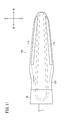
- FIG. 2 is a partial front view showing an enlarged front upper portion of the motorcycle shown in FIG.
- FIG. 3 is an explanatory diagram showing a state of the motorcycle shown in FIG. 1 as viewed from the direction of arrow A.
- FIG. 4 is a table showing the lighting timing of the ON indicator and OFF indicator of the TCS of FIG.
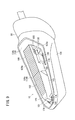
- FIG. 5 is a front view showing the blinker lamp of FIG. 6 is a cross-sectional view taken along the line VI-VI of the blinker lamp of FIG. 7 is a cross-sectional view of the blinker lamp of FIG. 5 taken along the line VII-VII.
- FIG. 5 is a schematic side view showing a straddle-type motorcycle having a lighting device according to an embodiment of the present invention.
- FIG. 2 is a partial front view showing an enlarged front upper portion of the motorcycle shown in FIG.
- FIG. 3 is an
- FIG. 8 is a front view showing a state in which the outer lens of the blinker lamp of FIG. 5 is removed.
- FIG. 9 is a perspective view showing the blinker lamp of FIG.
- FIG. 10 is a front view showing a state in which the inner lens of the blinker lamp of FIG. 8 is removed.
- FIG. 11 is a rear view of the blinker lamp of FIG.
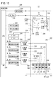
- FIG. 12 is a block diagram schematically showing a circuit configuration of a blinker lamp lighting control system.
- FIG. 1 is a schematic side view showing a straddle-type motorcycle (hereinafter also simply referred to as a motorcycle) 12 having a lighting device (blinker lamp) 10 according to an embodiment of the present invention.
- a straddle-type motorcycle hereinafter also simply referred to as a motorcycle
- a lighting device blink lamp
- the present invention will be described in detail by exemplifying the saddle riding type motorcycle.
- the present invention is not limited to this, and various vehicles (for example, other types of motor vehicles capable of traveling on the road) are described.
- the present invention can also be applied to a two-wheeled vehicle, a motor-driven bicycle, or an automobile.
- the front and rear and up and down directions will be described with reference to the arrow direction shown in FIG. 1, and the direction viewed from the driver seated on the vehicle body will be the reference.
- the left and right directions (see the arrow direction in FIG. 2) will be described.
- a motorcycle 12 includes a vehicle body frame 14 constituting a vehicle body, and a pair of left and right front forks 18 rotatably supported by a head pipe 16 provided at a front end portion of the vehicle body frame 14.
- the front wheel (steering wheel) 20 attached to the front fork 18, the engine 22 that is a driving source of the motorcycle 12 supported by the body frame 14, and the pivot portion 24 below the body frame 14 are swingably supported.
- a swing arm 26 and a rear wheel (drive wheel) 28 attached to the rear end of the swing arm 26 are provided.
- the body frame 14 is constituted by, for example, a tube frame made of cast aluminum having high rigidity.
- the vehicle body frame 14 includes a pair of left and right main frames 30 that branch left and right from the head pipe 16 and extend obliquely downward, and a pivot portion 24 that is connected to the rear portion of the main frame 30 and extends downward.
- a pair of left and right seat frames 32 attached to the rear portion of the main frame 30 and extending obliquely upward. That is, the motorcycle 12 according to the present embodiment has a frame structure that can support the internal mechanism of the vehicle body while reducing the number of frames of the vehicle body frame 14.
- the pair of left and right front forks 18 extend substantially in the vertical direction at the front portion of the vehicle body, and a top bridge 34 (see FIG. 3) is attached to the upper end portion thereof.
- a headlight 36 that lights the front of the vehicle body is disposed on the upper side of the front fork 18.
- a handle 38 capable of steering the front wheel 20 is attached to the top bridge 34.
- the handle 38 includes a handle bar 39 that extends symmetrically toward the outer side in the vehicle width direction, and grips 38 a that are attached to both left and right ends of the handle bar 39.
- a pair of left and right rearview mirrors 40 are attached to the middle portion of the handle bar 39.
- the front wheel 20 is rotatably supported at the lower end portion of the front fork 18, and a brake device (disc brake) 20a is mounted on the side surface thereof.
- a front fender 42 that covers the upper side of the front wheel 20 is attached to the lower side of the front fork 18 (upper side of the front wheel 20).
- the engine 22 can be, for example, a water-cooled 4-stroke V-type 4-cylinder engine.
- the engine 22 is provided with a crankcase 44 disposed on the lower side, a front cylinder 46 extending obliquely forward and upward from the crankcase 44, and obliquely rearward and upward behind the crankcase 44. And a rear cylinder 48.
- the engine 22 is fixed and supported by the main frame 30 at an intermediate portion sandwiched between the front cylinder 46 and the rear cylinder 48, and the posture is fixed by the rear portion of the rear cylinder 48 being fixedly supported by the pivot portion 24.
- a spark plug for performing combustion Inside the front cylinder 46 and the rear cylinder 48 are accommodated a spark plug for performing combustion and a piston for performing compression (both not shown).
- a crankshaft and an engine output shaft connected to the piston via a connecting rod are supported inside the crankcase 44.
- the engine 22 employs a dual clutch transmission (DCT) that can switch between two clutches. Thereby, the motorcycle 12 can select two types of travel modes (for example, automatic mode and manual mode).
- the rotational driving force of the engine 22 is transmitted by a drive shaft (not shown) extending rearward from the crankcase 44 and transmitted to the rear wheel 28 via the drive shaft.
- a radiator 50 that dissipates heat from the engine 22 is disposed in front of the front cylinder 46.
- a fuel tank 52 and an intake device 54 are mounted above the engine 22.
- the intake device 54 includes a throttle body 56 connected to the upper inside of the front cylinder 46 and the rear cylinder 48, and an air cleaner 58 connected to the upstream end of the throttle body 56 via an intake pipe (not shown).
- the throttle body 56 employs TBW (throttle-by-wire) that changes the cross-sectional area of the internal throttle valve by driving an actuator.
- the intake device 54 removes dust and the like of air taken in during traveling by an air cleaner 58 and injects the air from the throttle body 56 to the front cylinder 46 and the rear cylinder 48 together with fuel.
- an exhaust device 60 is provided below the engine 22.
- the exhaust device 60 is connected to the front of the front cylinder 46 and the rear of the rear cylinder 48 and extends rearward so as to wrap around the lower portion of the crankcase 44.
- the exhaust device 60 communicates with the exhaust tube 62 and An exhaust muffler 64 disposed on the right side, and has a function of exhausting exhaust gas from the engine 22.
- the swing arm 26 extends substantially horizontally rearward from the pivot portion 24, and a rear wheel 28 is rotatably supported at the rear end portion thereof.
- a rear wheel brake device (disc brake) 28 a is mounted on a side surface of the rear wheel 28.
- a rear cushion 66 that elastically connects the main frame 30 and the swing arm 26 is attached to the front upper portion of the swing arm 26.
- the rear cushion 66 has a function to absorb timely vibration during traveling of the motorcycle 12.
- the seat frame 32 is provided with a seat 68 on which a passenger (driver and passenger) is placed.
- a so-called tandem seat is adopted, which includes a front seat 68a on which a driver sits and a rear seat 68b on which a passenger sits behind the front seat 68a.
- a rear fender 70 is attached to the rear part of the seat frame 32 and extends rearward and extends obliquely downward from the lower side of the rear part.
- a tail lamp unit 72 is attached to the rear fender 70 as an illumination part on the rear side of the vehicle body.
- the tail lamp unit 72 is provided with a brake lamp 72a and a rear side blinker lamp 73, and a lighting operation is performed based on the operation of the driver.
- the motorcycle 12 is provided with a vehicle body cover 74 that forms a design surface (appearance) of the vehicle body in the longitudinal direction of the vehicle body.
- the vehicle body cover 74 is made of, for example, a polymer material such as acrylonitrile / butadiene / styrene (ABS), fiber reinforced plastic (FRP), or polypropylene (PP).
- the body cover 74 includes a headlight cover 76 that covers the periphery of the headlight 36, a screen support cover 80 that supports the screen 78 at the top of the headlight 36, a handle cover 82 that covers the front of the handle 38, and the headlight 36.
- a pair of left and right side cowls 84 extending rearward from both side surfaces and a rear cowl 86 extending rearward and upward together with the seat frame 32 and covering both side surfaces of the seat frame 32 are provided.
- the vehicle body cover 74 includes a cowl support stay 88 that supports the headlight 36 and the screen support cover 80, and the cowl support stay 88 is fixed to the front portion of the main frame 30.
- the cowl support stay 88 supports a meter unit 90 disposed on the rear side of the headlight 36, and a blinker lamp (front blinker lamp) 10 is attached to both side surfaces thereof.
- FIG. 2 is a partial front view showing an enlarged front upper portion of the motorcycle 12 of FIG.
- the headlight cover 76 and the screen 78 (screen support cover 80) constitute a design at the front upper part of the vehicle body, and are formed in a streamline that gently inclines in the vehicle width direction and upward from the center of the tip toward the rear. Has been.
- the headlight cover 76 has a substantially triangular design surface with the left and right end portions on the upper side and the central portion on the lower side as vertices in front view by covering both sides with the side cowls 84.
- the headlight cover 76 has an opening 76a so that the lens surface 36a of the headlight 36 is visually recognized in a substantially heart shape.
- the left and right side portions of the headlight cover 76 are formed with recesses 76b.
- the recesses 76b are engaged with the side cowls 84 to form openings that communicate with the inside of the vehicle body cover 74. Is guided to the air cleaner 58.
- the headlight 36 is housed inside the headlight cover 76, and the lens surface 36a is exposed forward.
- the headlight 36 includes a low beam bulb 92 on the upper side of the central portion and a high beam bulb 94 on the lower side of the central portion, and enables low beam and high beam lighting as a headlamp.
- a pair of left and right position light bulbs 96 are attached to the outside of the headlight 36 in the vehicle width direction.
- the winker lamp 10 has a base end portion 10a attached to a cowl support stay 88 (see FIG. 1) via an attachment member 98, and extends substantially horizontally outward in the vehicle width direction.
- the front end portion 10b of the blinker lamp 10 on the outer side in the vehicle width direction is set when a line segment Ls connecting the lower end top portion of the opening 76a of the headlight cover 76 and the front end top portion of the handle cover 82 on the outer side in the vehicle width direction is set.
- the blinker lamp 10 is disposed obliquely to the position light bulb 96 of the headlight 36 when the upper part of the vehicle body is viewed from the front. In addition to blinking as a direction instruction signal during traveling, the blinker lamp 10 is lit with a light amount smaller than that of the direction instruction signal simultaneously with the lighting of the position light bulb 96. Thereby, the blinker lamp 10 has a role as a position light (auxiliary light). That is, in the motorcycle 12 according to the present embodiment, the position lights are turned on from a total of four of the right and left two position light bulbs 96 of the headlight 36 and the two left and right blinker lamps 10. Visibility from the vehicle can be improved.
- the vehicle body cover 74 extends around the side cowls 84 from the side surfaces of the pair of left and right main frames 30 and extends forward, and is connected to the lower portion of the headlight cover 76.
- a guard pipe 100 is provided.
- the cowl guard pipe 100 constitutes the design of the front portion of the vehicle body and prevents the vehicle body cover 74 from being scratched when the vehicle body rolls over.
- FIG. 3 is an explanatory diagram showing a state of the motorcycle 12 shown in FIG.
- a handle switch case 41 of the switch unit 208 (see FIG. 12) is provided in the vicinity of the handle 38 of the motorcycle 12.
- a hazard switch HS that operates blinking of a hazard (hazard operation)
- a headlight changeover switch HLS that operates switching between high beam and low beam of the headlight 36
- blinking of a blinker a winker switch WS for operating (a winker operation) is provided.
- the motorcycle 12 has a meter unit 90 that digitally displays the traveling speed and the rotational speed of the engine 22, and this meter unit 90 is located behind the headlight 36 (see FIG. 1). Is supported by a cowl support stay 88.
- the meter unit 90 is disposed in front of the handle 38, and a speedometer liquid crystal screen 102 for displaying the speed and a tachometer liquid crystal screen 104 for displaying the rotational speed of the engine 22 are provided on the facing surface facing the driver. Yes.
- a plurality of indicators (display lamps) for notifying the state of the driving system and the electric system of the motorcycle 12 are provided on the upper side of the opposing surface of the meter unit 90. Specifically, the left winker indicator 106, the high beam indicator 108, the neutral indicator 110, the TCS (Traction Control System) ON indicator 112, the TCS OFF indicator 114, and the right winker indicator 116 in order from the left as viewed from the driver. Is provided.
- the left blinker indicator 106 and the right blinker indicator 116 are turned on when a direction is indicated by the left and right front blinker lamps 10 and the rear blinker lamp 73, and the high beam indicator 108 is a high beam when the headlight 36 lights.
- the neutral indicator 110 is lit when the clutch is neutral, and the ON indicator 112 and the OFF indicator 114 of the TCS perform a predetermined lighting operation based on the state of the TCS.
- TCS is a system that controls the driving of the motorcycle 12 by calculating the slip ratio from the vehicle speed signals of the front wheels 20 and the rear wheels 28 when the motorcycle 12 is traveling. For example, if the TCS determines that the rear wheel 28 has slipped based on the calculated slip ratio, the TCS adjusts the throttle (TH) opening by the TBW of the throttle body 56 so that the target slip ratio is set in advance. And configured to control the output of the fuel. Thereby, the motorcycle 12 can control the rotation of the engine 22, that is, the rotation of the rear wheel 28, and can prevent slipping during traveling.
- TH throttle
- the TCS is switched between an ON (control execution) state and an OFF (control stop) state when a switching operation is performed by the driver.
- the TCS switching button 118 is provided in a notch recess 84 a formed on the upper surface of the left side cowl 84. More specifically, the switch button 118 of the TCS is provided at a front position separated from the handle switch case 41 attached to the handle 38 by a predetermined distance D1 (see FIG. 1), and when the motorcycle 12 travels. This prevents the driver from releasing the handle 38 and inadvertently operating the switch button 118 of the TCS.
- the driver can switch from ON to OFF by long-pressing the switching button 118, and can switch from OFF to ON by long-pressing the switching button again. Further, for example, the TCS OFF state continues until IGN (ignition: not shown) is stopped (that is, the engine 22 is stopped), and automatically returns to the ON state when IGN driving is started again. You may comprise.
- FIG. 4 is a table showing the lighting timing of the ON indicator 112 and the OFF indicator 114 of the TCS of FIG.
- the TCS ON indicator 112 and the OFF indicator 114 appropriately display the TCS state of the motorcycle 12 by two lighting states. In this case, when the motorcycle 12 starts to drive the IGN, both the ON indicator 112 and the OFF indicator 114 of the TCS are turned on for about 2 seconds in order to notify that electricity is supplied to the electric system.
- the motorcycle 12 checks whether the TCS operates normally as a self-diagnosis (initial diagnosis) before driving. At this time, the TCS OFF indicator 114 is turned off, and only the TCS ON indicator 112 is turned on. When the initial diagnosis of TCS is completed, the TCS ON indicator 112 is automatically turned off.
- the TCS ON indicator 112 and the OFF indicator 114 are displayed during normal travel (while it is determined that the rear wheel 28 has not slipped by the TCS). Both are turned off.
- the TCS performs the drive control of the TBW as described above.
- the TCS ON indicator 112 is blinked. This can inform the driver that the TCS is operating.
- the TCS switching button 118 is pressed and held by the driver to drive the motorcycle 12 with the TCS turned OFF (control stop)
- the TSC OFF indicator 114 is always lit. As a result, the driver can be notified that the TCS control is not being performed.
- the TCS ON indicator 112 is turned on. This can inform the driver that the TCS is not operating normally.
- the motorcycle 12 can easily inform the driver of the operation status of the TCS by the lighting state of the ON indicator 112 and the OFF indicator 114 of the TCS.
- the configuration of the blinker lamp (front blinker lamp) 10 according to the present invention will be described with reference to FIGS.
- the blinker lamp 10 on the right side as viewed from the driver will be described in detail, and the description of the blinker lamp 10 on the left side that can have a symmetrical configuration with the blinker lamp 10 will be omitted.
- FIG. 5 is a front view showing the winker lamp 10 of FIG. 1
- FIG. 6 is a cross-sectional view taken along the line VI-VI of the winker lamp 10 of FIG. 5
- FIG. 8 is a cross-sectional view taken along line VII
- FIG. 8 is a front view showing a state in which the outer lens of the winker lamp 10 of FIG. 5 is removed
- FIG. 9 is a perspective view showing the winker lamp 10 of FIG.
- the blinker lamp 10 includes a base member 120, an outer lens 122 attached to the front portion of the base member 120, and a light emitting diode (hereinafter referred to as LED 124).
- a substrate 126 housed in an internal space 125 formed by the member 120 and the outer lens 122 and an inner lens 128 disposed between the outer lens 122 and the substrate 126 are provided.
- a harness 130 that is electrically connected to the LED 124 is connected to a mounting surface 126 a of a substrate 126 on which the LED 124 is mounted.
- the base member 120 is attached to the attachment member 98 on the base end side, and gradually widens in the vertical direction from the base end side in a front view, and is located in the middle 120 a near the base end. It is formed in an outer shape that gradually becomes narrower from the top to the center of the top and bottom. As shown in FIGS. 6 and 7, the base member 120 is formed in a substantially concave shape (a bowl shape) in a side sectional view, and a substrate 126 is accommodated in the concave portion.
- a substantially concave shape a bowl shape
- the base member 120 has a plurality of (three in FIG. 6) protruding support portions 132 protruding forward from the rear side wall portion (substantially concave bottom portion) 120b.
- the protruding support portion 132 supports the substrate 126 at a predetermined interval from the rear side wall portion 120b. Thereby, the blinker lamp 10 can diffuse (heat radiate) the heat accompanying the light emission of the LED 124 to the surrounding air.
- the base member 120 is formed of a synthetic resin material that can withstand the temperature rise accompanying the light emission of the LED 124.
- a synthetic resin material for example, BMC (Bulk Molding Compound) resin or the like is preferably used.
- an attachment surface 134 to which the outer lens 122 and the inner lens 128 are attached is formed on the front surface side of the base member 120.
- a flat portion (flat surface) 134a is formed on the mounting surface 134 from the midway location 120a toward the vehicle width direction outer side, and an inclined portion is inclined obliquely forward from the midway location 120a toward the vehicle width direction inner side. 134b is formed.
- a harness passage 136 is formed inside the attachment member 98, and this harness passage 136 is formed in a crank shape from the base end side toward the outer side in the vehicle width direction.
- the harness 130 is guided from the proximal end side of the attachment member 98 to the base member 120 via the harness passage 136.
- a mounting screw 138 is inserted through the washer 138a toward the outer side in the vehicle width direction inside the harness passage 136, and the base member 120 is screwed to the mounting screw 138 to be mounted on the mounting member 98.
- the attachment member 98 is preferably molded from a synthetic resin material having an elastic force such as synthetic rubber. Thus, since the attachment member 98 has an elastic force, the vibration etc. at the time of driving
- the head of the mounting bolt 142 is embedded in the base end side of the mounting member 98, and the tip of the mounting bolt 142 extends inward in the vehicle width direction (base end direction).
- the mounting bolt 142 is embedded in the mounting member 98 with the flange member 144 mounted when the mounting member 98 is molded. Thus, the mounting bolt 142 is fixed to the mounting member 98 and is prevented from falling off.
- the attachment bolt 142 is attached to the support member 140 attached to the cowl support stay 88.
- the support member 140 is formed of a resin material so as to be fitted to the cowl support stay 88.
- the mounting bolt 142 is inserted into the bolt insertion hole 140a of the support member 140, and is fixedly supported by the support member 140 by tightening the distal end side to the nut 142a. Accordingly, the winker lamp 10 is supported by the cowl support stay 88 via the attachment member 98 and the support member 140.
- the base member 120 has two holes (a first hole 146 and a second hole 148) formed on an end surface to which the mounting member 98 is attached.
- the first hole 146 and the second hole 148 are formed as follows.
- the internal space 125 (partial space 172 described later) communicates with the base member 120 and the outer lens 122.
- the first hole 146 has a larger diameter than the second hole 148, and a grommet (holding member) 150 that holds the harness 130 is inserted into the first hole 146.
- the grommet 150 has an insertion passage 152 through which the harness 130 is inserted, and a plurality of protrusions 152 a that are closely attached to the outer peripheral surface of the harness 130 are formed on the inner peripheral surface of the insertion passage 152.
- the grommet 150 has a flange 150a having a diameter larger than that of the first hole 146 of the base member 120 at one end disposed on the inner space 125 side, and a substantially intermediate portion that extends inward in the vehicle width direction.
- the projection 150b has a configuration in which the flange 150a and the projection 150b are engaged with both opening ends of the first hole 146. That is, the grommet 150 has a function of inserting and holding the harness 130 while preventing water from entering between the harness 130 and the insertion passage 152 and between the first hole 146 and the grommet 150.
- the second hole 148 of the mounting member 98 is formed at a position where the opening end on the inner space 125 side faces the substrate 126 and the LED 124, and has a function of ventilating the inner space 125.
- the blinker lamp 10 can be made equal to the external air pressure with respect to the pressure change in the internal space 125 due to heat generated by the light emission of the LED 124 through the second hole 148.
- a vent sheet 154 that absorbs water and allows only air to flow is attached to the opening end on the proximal end side of the second hole portion 148 to prevent water from entering the internal space 125. .
- the outer lens 122 of the blinker lamp 10 is formed of a synthetic resin material having high transparency, and is attached to the front portion of the base member 120, thereby constituting a lens surface on the front surface of the blinker lamp 10. As shown in FIG. 5, the outer lens 122 is formed in an outer shape that substantially matches the peripheral edge of the base member 120 in a front view. Further, the outer lens 122 is formed in a substantially concave shape in a side sectional view (see FIG. 6 and FIG. 7), and the rear opening end portion 122a is a surface shape (flat portion 134a) of the mounting surface 134 of the base member 120. And an inclined portion 134b). In other words, the outer lens 122 can be engaged with the mounting surface 134 of the base member 120 without any gap, and can be welded to the base member 120.
- the outer lens 122 is attached to the base member 120 by vibration welding that is vibrated and joined to the base member 120 in the horizontal direction.
- the winker lamp 10 is configured such that rainwater or the like does not enter the internal space 125 by this vibration welding.
- a lens cut (hereinafter referred to as an outer side lens cut portion 122b) is applied to the inner surface (the surface on the inner space 125 side) of the outer lens 122.
- the outer lens cut portion 122b has a function of diffusing light emitted from the LED 124 up and down, with a cut line extending in the left-right direction (vehicle width direction).
- the outer surface of the outer lens 122 is formed on a smooth surface that is not subjected to lens cutting so that mud, dust, and the like are less likely to adhere to the outer lens 122.
- the board 126 attached to the base member 120 is a long plate-like member extending in the vehicle width direction, and two LEDs 124 are mounted on the surface (mounting surface 126a).
- the LED 124 is mounted on the predetermined conductive pattern (not shown) printed on the mounting surface 126a of the substrate 126 by reflow soldering.
- the substrate 126 employs a structure in which a substrate material (for example, a glass epoxy substrate or paper phenol) and copper foil are alternately laminated. Further, a hollow cylindrical through hole (not shown) is formed at a position opposite to the mounting position of the LED 124, and a conductive pattern formed on the front surface (mounting surface 126a) and a back surface side are formed. The conductive pattern is routed. A copper foil is also applied to the surface of the through hole.
- the substrate 126 can easily guide the heat generated by the light emission of the LED 124 from the surface (mounting surface 126a) to the lower layer and the space on the back side by the laminated structure and the through hole. Thereby, since heat diffuses, it is possible to prevent heat from concentrating around the LED 124 and to improve the heat dissipation of the blinker lamp 10.
- the board 126 has a fixing screw insertion hole 156 at the center, and a protruding support part insertion hole (substrate welding part) 158 between the outer end part in the vehicle width direction and the connection part between the LED 124 and the harness 130.
- a fixing screw 160 is inserted into the fixing screw insertion hole 156, and the fixing screw 160 is screwed into the screw hole 132 a of the central protruding support portion 132 protruding from the rear side wall portion 120 b of the base member 120.
- left and right protruding support portions 132 are inserted into the protruding support portion insertion holes 158, and the protruding support portions 132 are subjected to high-frequency caulking.
- the protrusion support part insertion hole 158 and its peripheral part are welded to the protrusion support part 132.
- the protruding support portion insertion hole 158 it is possible to reduce the number of screws for screwing the substrate 126 and to reduce the number of components.
- a harness 130 that is electrically connected to the two LEDs 124 via a conductive pattern is connected to the mounting surface 126a of the substrate 126.
- the harness 130 has a base end connected to the electric system of the motorcycle 12 and has a function of supplying power to the LED 124.
- the material of the harness 130 is not particularly limited, but it is preferable to apply a synthetic resin material having insulation and flexibility, and a synthetic resin material that can withstand the heat generated by the light emission of the LED 124 is preferable.
- the two LEDs 124 mounted on the substrate 126 those that emit a light amount and a color temperature that can be used as a light source of the blinker lamp 10 are applied.
- the blinker lamp 10 since the blinker lamp 10 is intended to inform the surroundings of the turn direction of the vehicle body, it is preferable to apply an element that emits light with high brightness and wide directivity. Thereby, the diffusion (irradiation range) of light at the time of irradiation of the blinker lamp 10 can be widened.
- the inner lens 128 disposed in the internal space 125 is directed toward the LED 124 at a position facing the lens cut portion 162 formed on the front surface of the base portion 161 extending in the vehicle width direction and the LED 124.
- the protrusion part 164 which protrudes, and the collar part 166 extended in the vehicle width direction inner side from the base 161 side of the protrusion part 164 are provided.
- the base portion 161 of the inner lens 128 has welding protrusions 168 that are welded to the base member 120 on the front end side (the vehicle width direction outer side) and the vehicle width direction inner side. Is provided.
- the welding protrusion 168 is welded to the mounting surface 134 of the base member 120 by vibration welding. Accordingly, the inner lens 128 is supported by the base member 120 and is disposed at a predetermined position in the internal space 125 of the blinker lamp 10.
- the lens cut portion 162 has a cut line extending in the vertical direction, and a plurality of the cut lines are arranged in the vehicle width direction. As shown in FIGS. 6 and 9, the lens surface between the two cut lines is curved in an arc shape. The arc-shaped lens surface can diffuse the light of the LED 124 transmitted through the inner lens 128 in the left-right direction. That is, the lens cut portion 162 has a function of dispersing the transmission of light linearly traveling from the substrate 126 to the outer lens 122 in a front view.
- the protrusions 164 are provided side by side on the back surface (rear surface) side of the inner lens 128 corresponding to the two LEDs 124 mounted on the substrate 126.
- the protruding portion 164 is formed in a substantially spindle shape that is reduced in a curved shape from the base 161 side (lens cut portion 162 side) toward the LED 124 in a plan sectional view, and a top portion thereof. Is a cutout portion 170 cut out in the proximal direction.
- the protruding portion 164 is separated from the LED 124 by the notch portion 170 at a predetermined interval, and heat generated by the light emission of the LED 124 can be prevented from being transmitted to the inner lens 128.
- the collar portion 166 is a portion extending further inward in the vehicle width direction from the protruding portion 164 on the inner side in the vehicle width direction (right side in FIG. 6).
- the flange portion 166 is thinner than the protruding portion 164 and is formed in a flat plate shape, and a lens cut portion 162 is continuously provided on the front surface thereof. Further, the back surface (rear surface) of the flange portion 166 is formed in a flat shape that is connected to the base end side (base portion 161) of the protruding portion 164 and is parallel to the substrate 126 facing rearward.
- the inner lens 128 is welded to the base member 120 and supported at a predetermined position in the internal space 125, so that the back surface of the flange portion 166 to the front surface of the substrate 126.
- a relatively wide partial space 172 is formed between them. That is, the partial space 172 is a space surrounded by the protruding portion 164 and the flange portion 166 of the inner lens 128, the board 126, and the side surface on the inner side in the vehicle width direction of the base member 120, and the harness 130 is arranged in the partial space 172.
- the harness 130 extends from the insertion path 152 of the grommet 150 provided on the side surface of the base member 120 to the partial space 172 and is connected to the surface of the substrate 126 (mounting surface 126a).
- the collar part 166 has a function of hiding the harness 130 extending to the partial space 172 in the front view by having the lens cut part 162 on the front surface. That is, the visual recognition of the harness 130 is made by reflecting external light incident from the outside to the harness 130, but since the light reflected by the harness 130 can be diffused at the lens cut portion 162, the harness 130 can be diffused. It can be difficult to see.
- the flange portion 166 extends until the end portion on the inner side in the vehicle width direction substantially coincides with one end portion of the grommet 150.
- the collar portion 166 extends to one end portion of the grommet 150 protruding into the partial space 172, so that the harness 130 extending from the end portion of the grommet 150 to the partial space 172 is covered with the collar portion 166. It is possible to make the harness 130 more difficult to see.
- the assembly of the blinker lamp 10 according to the present embodiment is performed by sequentially welding each member (the substrate 126, the inner lens 128, and the outer lens 122) to the base member 120.
- each member the substrate 126, the inner lens 128, and the outer lens 122
- a pair of groove portions (support portions) 174 are formed on the back surface (rear surface) of the base member 120, as shown in FIG. 11, a pair of groove portions (support portions) 174 are formed.
- the pair of grooves 174 are cut in the vehicle width direction at the top and bottom of the base member 120, and the bottoms thereof are formed flat (see FIG. 7).
- the protruding support portion insertion hole 158 is fitted into the protruding support portion 132 of the base member 120, and the fixing screw 160 is screwed into the screw hole 132 a via the fixing screw insertion hole 156.
- the substrate 126 is primarily fixed (screwed).
- substrate 126 and the base member 120 are firmly fixed by performing the high frequency crimping of the protrusion support part 132 inserted in the protrusion support part insertion hole 158.
- FIG. As described above, by partially welding the substrate 126 and the base member 120, the number of screws for screwing the substrate 126 is reduced. For this reason, the number of parts can be reduced, and since it is not necessary to provide a plurality of screw holes 132a in the base member 120, the size of the base member 120 can be reduced.
- the two LEDs 124 are mounted on the substrate 126 so that the terminal 124a of the LED 124 and the two protruding support portion insertion holes 158 are separated by a predetermined distance D2. Thereby, it is possible to prevent the welded material of the protruding support portion 132 from adhering to the terminal 124a of the LED 124 by high-frequency caulking.
- the inner lens 128 is welded to the flat portion 134a of the base member 120.
- the welding protrusion 168 provided in the base 161 of the inner lens 128 and the mounting surface 134 of the base member 120 are fixed by vibration welding.
- a plurality of wall portions 176 are erected on the upper and lower sides of the welded portion to which the welding protrusion 168 is welded.
- the wall portion 176 has a function of preventing a welded product generated by vibration welding the inner lens 128 from popping out on the attachment surface 134 and further toward the welded portion side of the outer lens 122. Thereby, it can suppress that a welding thing adheres on the attachment surface 134 etc., and it becomes difficult to weld the outer lens 122, or an external appearance property is impaired.
- 162 and the flange portion 166 are arranged closer to the outer lens 122 than the virtual straight line Li, and the top side of the protrusion 164 is arranged closer to the substrate 126 than the virtual straight line Li.
- the blinker lamp 10 is provided with the inner lens 128 (projecting portion 164) so as to fill most of the internal space 125 in a plan view. ) And the left and right direction (vehicle width direction), the LED 124 and the harness 130 can be prevented from being visually recognized.
- the outer lens 122 is welded to the outer surface of the mounting surface 134 of the base member 120 relative to the mounting surface of the inner lens 128.
- the outer lens 122 is placed on the mounting surface 134 of the base member 120, and a boundary portion (welding portion) between the rear opening end of the outer lens 122 and the peripheral portion of the mounting surface 134 is formed. It is fixed by vibration welding.
- the outer lens 122 and the inner lens 128 are welded to the same flat portion 134a, the outer lens 122 and the inner lens 128 can be easily welded without greatly changing the height position of the welding surface.
- the wall portion 176 provided on the attachment surface 134 can prevent the welded material from moving toward the welded portion of the inner lens 128.
- the blinker lamp 10 is assembled as one unit to which the mutual members are fixed by welding the substrate 126, the inner lens 128, and the outer lens 122.
- FIG. 12 is a block diagram schematically showing a circuit configuration of the lighting control system 11 of the blinker lamp 10.
- the lighting control system 11 includes a pair of left and right (a total of four) blinker lamps (front blinker lamps) 10 and a rear blinker lamp 73 described above. Therefore, in the following description, in order to distinguish the four blinker lamps on the circuit, as shown in FIG. 12, the left front blinker lamp is denoted by reference numeral LF, the left rear blinker lamp is denoted by reference numeral LR, The lamp control system 11 will be described in detail with the reference symbol RF attached to the right front blinker lamp and the reference symbol RR attached to the right rear blinker lamp.
- the lighting control system 11 includes a blinker switch WS and a hazard switch HS for operating blinking of the blinker lamps LF, LR, RF, and RR, and further controls a blinking operation of the blinker lamps LF, LR, RF, and RR.
- a control unit) 200 In this case, the control circuit 200 blinks one of the left blinker lamps LF and LR and the right blinker lamps RF and RR based on the ON operation of the blinker switch WS by the driver (left blinker operation). Or the right blinker operation), and the hazard operation of blinking the left and right blinker lamps LF, LR, RF and RR together is controlled based on the ON operation of the hazard switch HS by the driver.
- the ignition switch IS, the winker switch WS, and the hazard switch HS are connected to the input side port of the control circuit 200. Further, a battery (power source) 202 is connected to the high side of each switch IS, WS, HS. That is, the lighting control system 11 according to the present embodiment employs a circuit structure in which the ignition switch IS, the blinker switch WS, and the hazard switch HS are disposed between the control circuit 200 and the battery 202. As a result, the control circuit 200 can detect the input voltage (signal) based on the ON operation of the winker switch WS and the hazard switch HS using the supply voltage of the battery 202, and the ON / OFF of the ignition switch IS and the winker switch WS. It is possible to accurately determine whether or not an OFF operation has been performed.
- an LED array (LF-LED, LR-LED, RF-LED and RR-LED) which is a light source of the blinker lamps LF, LR, RF and RR and a left blinker indicator 106 are provided at the output side port of the control circuit 200.
- the LED 204 that is the light source of the right blinker indicator 116 and the LED 206 that is the light source of the right blinker indicator 116 are connected.
- the LF-LED, LR-LED, RF-LED, RR-LED, and LEDs 204 and 206 are grounded to a common ground with the battery 202 on the downstream side.
- the ignition switch IS is a switch for starting and stopping the engine 22, and is connected between the control circuit 200 and the battery 202 via a wiring path.
- a key switch can be applied as the ignition switch IS.
- the ignition switch IS is turned on (for example, the key is rotated)
- the battery 202 and the control circuit 200 are energized and power supply to the control circuit 200 is started.
- a power supply voltage of 5 V is supplied from the battery 202 to the control circuit 200.
- the winker switch WS and the hazard switch HS are applied with a changeover switch that can convert a mechanical ON / OFF operation by the driver into an open / close of an electric circuit.
- These switches WS and HS are integrally disposed as a switch unit 208 on the left handlebar 39 (see FIG. 3). In this case, the winker switch WS and the hazard switch HS are connected in parallel in the unit.
- the winker switch WS includes two output side contacts (left switch contact 210a, right switch contact 210b) 210 connected to the control circuit 200, and one input side contact 212 connected to the battery 202 side. Is provided in the switch unit 208.
- the left switch contact 210a is a connection terminal for instructing blinking of the left blinker lamps LF and LR
- the right switch contact 210b is a connection terminal for instructing blinking of the right blinker lamps RF and RR.
- the winker switch WS is connected to either the left switch contact 210a or the right switch contact 210b when an operator (not shown) provided on the input contact 212 is tilted by the driver.
- the input voltage can be sent to the control circuit 200 from one of the output side contacts to which the connection is made.
- the hazard switch HS includes two output side contacts (left switch contact 214a, right switch contact 214b) 214 connected to the control circuit 200 and one input side contact connected to the battery 202 side. 216, and the respective contacts 214 and 216 are connected in parallel to the respective contacts 210 and 212 of the winker switch WS.
- a three-contact switch that mechanically connects three contacts by operating a button (not shown) can be applied.
- the switch device becomes a simple and inexpensive switch device.
- the hazard switch HS is turned on, the three contacts become conductive, and the input voltage can be simultaneously sent to the control circuit 200 from the left switch contact 214a and the right switch contact 214b.
- a harness (wiring) 218 that conducts to the control circuit 200 and a harness (wiring) 220 that conducts to the battery 202 are connected by connecting the winker switch WS and the hazard switch HS in parallel.
- the lighting control system 11 can wire from the battery 202 to the control circuit 200 by the harnesses 218 and 220 as described above, and the number of harnesses is reduced as compared with the configuration in which the winker switch WS and the hazard switch HS are separately connected. can do.
- the LF-LED, LR-LED, RF-LED, and RR-LED which are the light sources of the blinker lamps LF, LR, RF, and RR connected to the output port side of the control circuit 200, are explanations of the configuration of the blinker lamp 10.
- the LED 124 shown at times is applied.
- the light source is configured by connecting two LEDs 124 in series.
- the LF-LED, LR-LED, RF-LED, and RR-LED emit light when power is supplied from the control circuit 200 at a predetermined timing.
- the LEDs 204 and 206 of the left blinker indicator 106 and the right blinker indicator 116 emit light on the instrument panel 90a of the meter unit 90, and an LED having a light amount smaller than that of the LED 124 can be applied.
- the control circuit 200 of the lighting control system includes, as an internal circuit configuration, a left switch input port 222, a right switch input port 224, a SW input circuit (input voltage determination unit) 226, a holding circuit (holding unit) 228, It has a 5V regulator 230, a constant current circuit 232, a current detection circuit 234, an indicator driver 236, and a CPU (discriminating means) 238.
- the left switch input port 222 and the right switch input port 224 constitute part of the input side port of the control circuit 200.
- the left switch input port 222 has a high side connected to the left switch contacts 210a and 214a of the winker switch WS and the hazard switch HS, and a low side connected to the SW input circuit 226. That is, the left switch input port 222 inputs the input voltage sent from the left switch contacts 210 a and 214 a into the control circuit 200.
- the right switch input port 224 has a high side connected to the right switch contacts 210b and 214b of the winker switch WS and the hazard switch HS, and a low side connected to the SW input circuit 226. That is, the right switch input port 224 inputs the input voltage sent from the right switch contacts 210 b and 214 b into the control circuit 200.
- the SW input circuit 226 is provided between the left switch input port 222 and the CPU 238, and between the right switch input port 224 and the CPU 238, and receives the input voltage sent from the left switch input port 222 or the right switch input port 224. It has a circuit structure for discriminating voltage values.
- the voltage based on the leak current is input.
- the This leakage current is generated, for example, when rainwater or the like enters the winker switch WS or the hazard switch HS exposed to the external environment and the input side contacts 212 and 216 and the output side contacts 210 and 214 become conductive.
- the SW input circuit 226 cuts off the voltage based on the leakage current in the circuit, detects only the input voltage based on the ON operation of the winker switch WS and the hazard switch HS, and sends a predetermined signal (voltage value) to the downstream CPU 238. ) Is output.
- the holding circuit 228 has an input terminal connected to the CPU 238 and the battery 202 and an output terminal connected to the 5V regulator 230.
- the holding circuit 228 has a function of holding the connection state between the CPU 238 and the battery 202 based on the hazard operation of the blinker lamps LF, LR, RF, and RR determined by the CPU 238. That is, an ON signal is input to the holding circuit 228 from the CPU 238 during the hazard operation, and the holding circuit 228 connects the CPU 238 and the battery 202 while the ON signal is input.
- the lighting control system 11 includes the holding circuit 228, so that the hazard switch (HS) is turned off even if the ignition switch IS is turned off (the engine 22 is stopped) during the hazard operation. Until this is done, a power supply voltage is supplied from the battery 202 to the CPU 238 by the holding circuit 228 to perform the hazard operation. Thereby, the hazard operation can be maintained based on the drive control of the CPU 238. Therefore, the visibility of the vehicle can be improved even when the engine 22 is stopped.
- the hazard switch HS
- the holding circuit 228 cuts off the connection state between the battery 202 and the CPU 238 and stops the supply of the power supply voltage to the CPU 238. In this case, unless the ignition switch IS is turned on again, the power supply voltage from the battery 202 is cut off to the CPU 238.
- the blinker switch WS or the hazard switch HS is turned on.
- the 5V regulator 230 has an input terminal connected to the ignition switch IS and the output terminal of the holding circuit 228, and an output terminal connected to the CPU 238.
- the 5V regulator 230 has a function of stepping down the power supply voltage from the battery 202 and stably supplying 5V, which is a driving voltage value, to the CPU 238.
- the constant current circuit 232 has a function of supplying a predetermined amount of current to the blinker lamps LF, LR, RF, RR, and four constant current circuits 232 are provided corresponding to the blinker lamps LF, LR, RF, RR. Yes.
- Each constant current circuit 232 has an input terminal connected to the CPU 238 and the battery 202, and an output terminal connected to the current detection circuit 234 and the blinker lamps LF, LR, RF, RR LF-LED, LR-LED, RF-LED and RR- Connected to LED.
- the constant current circuit 232 has another circuit that supplies a constant current for position light from the battery 202.
- the current detection circuit 234 can feed back the operation of the constant current circuit 232 by connecting the input terminal to the constant current circuit 232 and connecting the output terminal to the CPU 238. That is, the constant current circuit 232 and LF-LED, LR-LED, if the RF-LED and RR-LED is broken, winker from CPU238 blink signal S L, S R, even when subjected to S H to the constant current circuit 232 Since no current flows, the disconnection state of the lighting control system 11 can be confirmed by detecting the current value with the current detection circuit 234.
- By providing the current detection circuit 234 for each of the four constant current circuits 232 it becomes possible to check the disconnection state of each constant current circuit 232, and it is possible to improve the accuracy of the disconnection detection.
- the indicator driver 236 has a function of supplying a predetermined amount of current to the LEDs 204 and 206 of the left blinker indicator 106 and the right blinker indicator 116, and two indicator drivers 236 are provided corresponding to the LEDs 204 and 206.
- Indicator driver 236 has an input terminal connected to the CPU 238, the output terminal is connected to LED204,206 left winker indicator 106 and the right winker indicator 116 receives the winker blink signal S L, S R, the S H from CPU 238 Then, a predetermined current is supplied to the LEDs 204 and 206 to emit light.
- the CPU 2308 for example, a well-known microprocessor (microcomputer) having an input / output interface and performing arithmetic processing therein can be applied.
- the CPU 238 may be provided in an ECU (Engine Control Unit: not shown) that controls the driving of the engine 22.
- the CPU 238 discriminates ON / OFF operations of the blinker switch WS and the hazard switch HS, and based on the discrimination results, the LF-LED, the LR-LED, the RF-LED and the RR-LED, the left blinker indicator 106, and the right blinker indicator
- the driving (light emission) of LEDs 204 and 206 of 116 is controlled.
- the CPU 238 stores in advance a discrimination program (not shown) for discriminating ON / OFF operations of the blinker switch WS and the hazard switch HS, and a predetermined discrimination processing flow is performed based on this program.
- the CPU 238 includes a register (not shown) having at least 3 bits for managing lighting of the blinker lamps LF, LR, RF, and RR for each operation.
- the left and right winker operations (left winker operation and right winker operation) and hazard operations by the blinker lamps LF, LR, RF, and RR set flags (left winker operation flag, right winker operation flag, and hazard operation flag) in predetermined registers. Is controlled by
- CPU238, for example, when the left winker operation flag 1 (True) by discriminating the process flow, and outputs the left winker lamp LF, the winker blink signal S L for blinking the LR to the constant current circuit 232, the right winker operation flag If There was a 1, and outputs the right winker lamps LF, winker blink signal S R for blinking the LR. Further, CPU 238, for example, if the flag hazard operation becomes 1 by discriminating the process flow, and outputs winker lamps LF, LR, RF, the winker blink signal S H for blinking the RR.
- the winker blink signal S L, S R, S H is a pulse signal that repeats ON-OFF in a predetermined cycle
- the left winker operation is determined by the determination processing flow, based on the right winker operation and the hazard operation, predetermined It is sent to the constant current circuit 232.
- the CPU 238 performs blinking by setting different flags for the left blinker operation, the right blinker operation, and the hazard operation, for example, the left blinker operation (or right blinker operation) and the blinking hazard operation
- the timing can be changed, and the blinker lamps LF, LR, RF, RR can be blinked with a high degree of freedom.
- the blinker lamp 10 according to the present embodiment is basically configured as described above. Next, the function and effect of the blinker lamp 10 will be described.
- the motorcycle 12 lights up with a small amount of light using the left and right blinker lamps 10 as position lights (auxiliary lights) during traveling, while the driver operates the blinker switch WS in the vicinity of the handle 38.
- the blinker lamp 10 on one side based on this operation is blinked with a large amount of light. Further, when the hazard switch HS is turned on, the left and right blinker lamps 10 are simultaneously blinked with a large amount of light.
- the LED 124 of the blinker lamp 10 is supplied with electric power whose light emission amount and light emission timing are controlled based on the above-described lighting operation from the control unit (not shown) of the electric system via the harness 130.
- the LED 124 when predetermined power is supplied, the LED 124 emits light LL that spreads radially from the front surface in accordance with the light emission characteristics.
- the light LL emitted from the LED 124 enters the protrusion 164 from the notch 170 of the inner lens 128 and is guided in the forward direction by the outer shape of the protrusion 164. Therefore, it is preferable that the protrusion 164 is formed in a curved shape so that the light LL emitted from the LED 124 can be totally reflected forward.
- the light LL emitted from the LED 124 can be easily guided to the front surface of the inner lens 128.
- the light LL transmitted through the protruding portion 164 reaches the lens cut portion 162 on the front surface of the inner lens 128, the light LL is diffused in the vehicle width direction (left-right direction) by the lens surface of the lens cut portion 162.
- the inner lens 128 can emit a large number of light rays traveling obliquely forward in the vehicle width direction from the front surface of the lens cut portion 162.
- the light traveling diagonally forward in the vehicle width direction enters the outer lens cut portion 122b of the outer lens 122 and is further diffused in the vertical direction.
- the blinker lamp 10 can irradiate the light beam of the LED 124 diffused in the vehicle width direction and the vertical direction from the front surface of the outer lens 122.
- the harness 130 for supplying power to the LED 124 is connected to the substrate 126 from the grommet 150 through the partial space 172.
- the partial space 172 is formed in a relatively wide space because the flange portion 166 is thinner than the protruding portion 164 and formed in a flat plate shape, and the harness 130 can be easily routed.
- the harness 130 is routed in the partial space 172 so that it is difficult to see from the outside of the blinker lamp 10. That is, since the collar part 166 located in front of the partial space 172 has the lens cut part 162 on the front surface, the light LH1 (for example, light reflected by the harness 130 from outside light) traveling forward from the harness 130 is received. It can diffuse in the vehicle width direction. For this reason, even if the collar part 166 is viewed from the front, the light LH1 from the harness 130 is dispersed into light rays that are hardly discernable, so that the harness 130 can be prevented from being visually recognized. In addition to this, the blinker lamp 10 diffuses the light LH1 from the harness 130 also in the vertical direction by the outer side lens cut portion 122b of the outer lens 122, so that the visibility of the harness 130 is further prevented.
- the light LH1 for example, light reflected by the harness 130 from outside light traveling forward from the harness 130 is received. It can diffuse in the vehicle width direction. For this reason, even if the
- the protrusion part 164 is arrange
- the blinker lamp 10 can make the harness 130 extending in the partial space 172 difficult to see by the inner lens 128. Thereby, for example, even if the harness 130 is not covered with another member such as the vehicle body cover 74, the harness 130 can be hidden. Therefore, when the blinker lamp 10 is irradiated, it is possible to secure a sufficient light emission area of the blinker lamp 10, thereby realizing a good lighting.
- the harness 130 can be connected to the board 126 at a position close to the LED 124, the board 126 can be downsized, and the blinker lamp 10 can be downsized.
- the blinker lamp 10 may set the connection portion of the board 126 and the harness 130 at a position overlapping the protruding portion 164 in front view. Thereby, the connection part of the board
- the inner lens 128 when assuming a virtual straight line Li extending in the vehicle width direction through the welded portion of the base member 120 and the inner lens 128, the inner lens 128 has a base 161 side outer than the virtual straight line Li.
- the top side of the protrusion 164 is closer to the substrate 126 than the virtual straight line Li. That is, the protruding portion 164 protrudes greatly, and when the blinker lamp 10 is viewed from an obliquely outer side in the vehicle width direction, the harness 130 is further difficult to see.
- the flange 166 and the protrusion 164 of the inner lens 128 are integrally formed, it is not necessary to prepare the flange 166 in addition to the inner lens 128, and the number of components can be reduced. As a result, the blinker lamp 10 can be easily assembled and the manufacturing cost can be reduced.
- the present invention is not limited to the above-described embodiment, and it is needless to say that various configurations and processes can be adopted without departing from the gist of the present invention.
- the inner lens 128 may be provided with the lens cut portion 162 on the back surface (rear surface) of the inner lens 128 without using the lens cut portion 162 on the front surface as in the present embodiment.
Priority Applications (7)
| Application Number | Priority Date | Filing Date | Title |
|---|---|---|---|
| CA2830363A CA2830363C (en) | 2011-03-31 | 2012-03-09 | Lighting device for vehicle |
| ES12764225.4T ES2546631T3 (es) | 2011-03-31 | 2012-03-09 | Dispositivo de iluminación para vehículo |
| AU2012234966A AU2012234966B2 (en) | 2011-03-31 | 2012-03-09 | Lighting device for vehicle |
| EP12764225.4A EP2693104B1 (en) | 2011-03-31 | 2012-03-09 | Lighting device for vehicle |
| US14/006,505 US9366407B2 (en) | 2011-03-31 | 2012-03-09 | Lighting device for vehicle |
| JP2013507334A JP5543665B2 (ja) | 2011-03-31 | 2012-03-09 | 車両の灯火装置 |
| CN201280015799.0A CN103502725B (zh) | 2011-03-31 | 2012-03-09 | 车辆的照明装置 |
Applications Claiming Priority (2)
| Application Number | Priority Date | Filing Date | Title |
|---|---|---|---|
| JP2011-081234 | 2011-03-31 | ||
| JP2011081234 | 2011-03-31 |
Publications (1)
| Publication Number | Publication Date |
|---|---|
| WO2012132831A1 true WO2012132831A1 (ja) | 2012-10-04 |
Family
ID=46930570
Family Applications (1)
| Application Number | Title | Priority Date | Filing Date |
|---|---|---|---|
| PCT/JP2012/056057 WO2012132831A1 (ja) | 2011-03-31 | 2012-03-09 | 車両の灯火装置 |
Country Status (9)
| Country | Link |
|---|---|
| US (1) | US9366407B2 (es) |
| EP (1) | EP2693104B1 (es) |
| JP (1) | JP5543665B2 (es) |
| CN (1) | CN103502725B (es) |
| AR (1) | AR088731A1 (es) |
| AU (1) | AU2012234966B2 (es) |
| CA (1) | CA2830363C (es) |
| ES (1) | ES2546631T3 (es) |
| WO (1) | WO2012132831A1 (es) |
Cited By (2)
| Publication number | Priority date | Publication date | Assignee | Title |
|---|---|---|---|---|
| WO2015098446A1 (ja) * | 2013-12-24 | 2015-07-02 | 本田技研工業株式会社 | ウインカ装置 |
| JP2019073059A (ja) * | 2017-10-12 | 2019-05-16 | 岡谷電機産業株式会社 | 鞍乗型車両用方向指示器 |
Families Citing this family (15)
| Publication number | Priority date | Publication date | Assignee | Title |
|---|---|---|---|---|
| US9216686B2 (en) * | 2011-03-31 | 2015-12-22 | Honda Motor Co., Ltd. | Vehicle lighting control system |
| JP5502238B1 (ja) * | 2012-08-06 | 2014-05-28 | 新電元工業株式会社 | 方向指示装置 |
| US9150149B2 (en) * | 2012-08-06 | 2015-10-06 | Shindengen Electric Manufacturing Co., Ltd. | Direction indicating apparatus |
| FR3011784B1 (fr) * | 2013-10-11 | 2017-04-21 | Valeo Vision Belgique | Dispositif d'eclairage ou de signalisation de vehicule automobile et procede d'assemblage correspondant |
| USD740983S1 (en) * | 2013-10-28 | 2015-10-13 | Koninklijke Philips N.V. | LED lamp for motorcycle |
| US9826594B2 (en) * | 2014-03-31 | 2017-11-21 | Honda Motor Co., Ltd. | Vehicle LED lighting device system |
| US20150377444A1 (en) * | 2014-06-26 | 2015-12-31 | Chin-Shu Yin | Headlight Switching Device for Car |
| JP6758874B2 (ja) * | 2016-03-29 | 2020-09-23 | 本田技研工業株式会社 | 灯火装置 |
| IT201600082345A1 (it) * | 2016-08-04 | 2018-02-04 | Piaggio & C Spa | Motociclo con controllo elettronico delle luci di emergenza |
| AU201617382S (en) * | 2016-12-30 | 2017-02-20 | 360 Two Pty Ltd | Motorcycle turn Indicator |
| USD866819S1 (en) * | 2017-10-31 | 2019-11-12 | T.Y.C. Brother Industrial Co., Ltd. | Vehicle lamp |
| JP6779952B2 (ja) * | 2018-09-21 | 2020-11-04 | 本田技研工業株式会社 | 鞍乗り型車両の灯体構造 |
| JP6911065B2 (ja) * | 2019-01-23 | 2021-07-28 | 本田技研工業株式会社 | ポジションライト一体型ウィンカ装置 |
| DE102020003849B4 (de) * | 2020-06-26 | 2023-07-20 | Motogadget Gmbh | Motorradleuchte zur Realisierung mindestens einer Leuchtenfunktion |
| CN112283670B (zh) * | 2020-12-28 | 2021-04-06 | 宁波雅佳达车业有限公司 | 一种电瓶车转向指示灯及电瓶车 |
Citations (4)
| Publication number | Priority date | Publication date | Assignee | Title |
|---|---|---|---|---|
| JP2008166023A (ja) * | 2006-12-27 | 2008-07-17 | Toyoda Gosei Co Ltd | 車両用灯具 |
| JP2008171604A (ja) * | 2007-01-10 | 2008-07-24 | Toyoda Gosei Co Ltd | リアコンビネーションランプ |
| JP4437952B2 (ja) | 2004-10-12 | 2010-03-24 | 本田技研工業株式会社 | 車両のテールランプ構造 |
| JP2010086687A (ja) * | 2008-09-30 | 2010-04-15 | Sakae Riken Kogyo Co Ltd | 車両用ランプ装置 |
Family Cites Families (11)
| Publication number | Priority date | Publication date | Assignee | Title |
|---|---|---|---|---|
| JPH0446322Y2 (es) * | 1988-08-02 | 1992-10-30 | ||
| US6520669B1 (en) * | 2000-06-19 | 2003-02-18 | Light Sciences Corporation | Flexible substrate mounted solid-state light sources for exterior vehicular lighting |
| US6502975B1 (en) * | 2001-08-20 | 2003-01-07 | Grote Industries, Inc. | Theft resistant lamp |
| US7374322B2 (en) * | 2002-02-06 | 2008-05-20 | Steen Ronald L | Center high mounted stop lamp including leds and tir lens |
| US6840661B2 (en) * | 2003-04-25 | 2005-01-11 | Gregg P. Desjardins | Flush fitting LED turn signal |
| US7452113B2 (en) * | 2004-03-09 | 2008-11-18 | Gentex Corporation | Optics for controlling the direction of light rays and assemblies incorporating the optics |
| US7513664B2 (en) * | 2004-05-10 | 2009-04-07 | Ichikoh Industries, Ltd. | Outside mirror apparatus including lighting device for vehicle |
| US20060028830A1 (en) * | 2004-08-04 | 2006-02-09 | Kevin Tsai | Automobile compound waterproof tail light |
| US20070183165A1 (en) * | 2006-02-07 | 2007-08-09 | Honeywell International Inc. | Direct Lighting Vehicular Lamp |
| JP4733006B2 (ja) * | 2006-12-11 | 2011-07-27 | 豊田合成株式会社 | 車両用灯具 |
| US7476014B1 (en) * | 2007-08-17 | 2009-01-13 | Visteon Global Technologies, Inc. | Vehicle headlamp unit |
-
2012
- 2012-03-09 ES ES12764225.4T patent/ES2546631T3/es active Active
- 2012-03-09 AU AU2012234966A patent/AU2012234966B2/en not_active Ceased
- 2012-03-09 EP EP12764225.4A patent/EP2693104B1/en active Active
- 2012-03-09 CN CN201280015799.0A patent/CN103502725B/zh active Active
- 2012-03-09 US US14/006,505 patent/US9366407B2/en active Active
- 2012-03-09 JP JP2013507334A patent/JP5543665B2/ja active Active
- 2012-03-09 WO PCT/JP2012/056057 patent/WO2012132831A1/ja active Application Filing
- 2012-03-09 CA CA2830363A patent/CA2830363C/en not_active Expired - Fee Related
- 2012-03-28 AR ARP120101060A patent/AR088731A1/es unknown
Patent Citations (4)
| Publication number | Priority date | Publication date | Assignee | Title |
|---|---|---|---|---|
| JP4437952B2 (ja) | 2004-10-12 | 2010-03-24 | 本田技研工業株式会社 | 車両のテールランプ構造 |
| JP2008166023A (ja) * | 2006-12-27 | 2008-07-17 | Toyoda Gosei Co Ltd | 車両用灯具 |
| JP2008171604A (ja) * | 2007-01-10 | 2008-07-24 | Toyoda Gosei Co Ltd | リアコンビネーションランプ |
| JP2010086687A (ja) * | 2008-09-30 | 2010-04-15 | Sakae Riken Kogyo Co Ltd | 車両用ランプ装置 |
Non-Patent Citations (1)
| Title |
|---|
| See also references of EP2693104A4 |
Cited By (3)
| Publication number | Priority date | Publication date | Assignee | Title |
|---|---|---|---|---|
| WO2015098446A1 (ja) * | 2013-12-24 | 2015-07-02 | 本田技研工業株式会社 | ウインカ装置 |
| US9975593B2 (en) | 2013-12-24 | 2018-05-22 | Honda Motor Co., Ltd. | Blinker device |
| JP2019073059A (ja) * | 2017-10-12 | 2019-05-16 | 岡谷電機産業株式会社 | 鞍乗型車両用方向指示器 |
Also Published As
| Publication number | Publication date |
|---|---|
| EP2693104A4 (en) | 2015-01-07 |
| AR088731A1 (es) | 2014-07-02 |
| JPWO2012132831A1 (ja) | 2014-07-28 |
| CN103502725B (zh) | 2015-11-25 |
| CA2830363C (en) | 2015-11-03 |
| AU2012234966B2 (en) | 2014-09-11 |
| AU2012234966A1 (en) | 2013-10-03 |
| US20140016336A1 (en) | 2014-01-16 |
| CA2830363A1 (en) | 2012-10-04 |
| EP2693104B1 (en) | 2015-08-26 |
| ES2546631T3 (es) | 2015-09-25 |
| EP2693104A1 (en) | 2014-02-05 |
| US9366407B2 (en) | 2016-06-14 |
| JP5543665B2 (ja) | 2014-07-09 |
| CN103502725A (zh) | 2014-01-08 |
Similar Documents
| Publication | Publication Date | Title |
|---|---|---|
| JP5543665B2 (ja) | 車両の灯火装置 | |
| JP5577457B2 (ja) | 車両の灯火制御システム | |
| US9593817B2 (en) | Headlight device of motorcycle | |
| EP2281738B1 (en) | Switch unit for a motorcycle | |
| EP2269900A1 (en) | Lighting system | |
| JP5335617B2 (ja) | 自動二輪車 | |
| JP6490728B2 (ja) | 鞍乗り型車両のヘッドライト構造 | |
| JP4086227B2 (ja) | バックミラー装置 | |
| EP3115286B1 (en) | Straddled vehicle | |
| JP5460182B2 (ja) | 自動二輪車のメータユニット | |
| WO2019187427A1 (ja) | 鞍乗型車両のコーナリングライト | |
| EP2327613B1 (en) | Warning lamp device for vehicles | |
| EP1780104B1 (en) | Winker mounting structure | |
| JP2019151315A (ja) | 鞍乗型車両のウインカランプ取付構造 | |
| CN115520305A (zh) | 跨乘式车辆 |
Legal Events
| Date | Code | Title | Description |
|---|---|---|---|
| 121 | Ep: the epo has been informed by wipo that ep was designated in this application |
Ref document number: 12764225 Country of ref document: EP Kind code of ref document: A1 |
|
| ENP | Entry into the national phase |
Ref document number: 2013507334 Country of ref document: JP Kind code of ref document: A |
|
| ENP | Entry into the national phase |
Ref document number: 2830363 Country of ref document: CA |
|
| WWE | Wipo information: entry into national phase |
Ref document number: 14006505 Country of ref document: US |
|
| WWE | Wipo information: entry into national phase |
Ref document number: 2012764225 Country of ref document: EP |
|
| NENP | Non-entry into the national phase |
Ref country code: DE |
|
| WWE | Wipo information: entry into national phase |
Ref document number: 1301005486 Country of ref document: TH |
|
| ENP | Entry into the national phase |
Ref document number: 2012234966 Country of ref document: AU Date of ref document: 20120309 Kind code of ref document: A |