WO2012132702A1 - 車両用駆動装置 - Google Patents
車両用駆動装置 Download PDFInfo
- Publication number
- WO2012132702A1 WO2012132702A1 PCT/JP2012/054779 JP2012054779W WO2012132702A1 WO 2012132702 A1 WO2012132702 A1 WO 2012132702A1 JP 2012054779 W JP2012054779 W JP 2012054779W WO 2012132702 A1 WO2012132702 A1 WO 2012132702A1
- Authority
- WO
- WIPO (PCT)
- Prior art keywords
- rotational speed
- internal combustion
- combustion engine
- electrical machine
- rotating electrical
- Prior art date
- Legal status (The legal status is an assumption and is not a legal conclusion. Google has not performed a legal analysis and makes no representation as to the accuracy of the status listed.)
- Ceased
Links
Images










Classifications
-
- F—MECHANICAL ENGINEERING; LIGHTING; HEATING; WEAPONS; BLASTING
- F02—COMBUSTION ENGINES; HOT-GAS OR COMBUSTION-PRODUCT ENGINE PLANTS
- F02N—STARTING OF COMBUSTION ENGINES; STARTING AIDS FOR SUCH ENGINES, NOT OTHERWISE PROVIDED FOR
- F02N15/00—Other power-operated starting apparatus; Component parts, details, or accessories, not provided for in, or of interest apart from groups F02N5/00 - F02N13/00
- F02N15/02—Gearing between starting-engines and started engines; Engagement or disengagement thereof
- F02N15/022—Gearing between starting-engines and started engines; Engagement or disengagement thereof the starter comprising an intermediate clutch
- F02N15/025—Gearing between starting-engines and started engines; Engagement or disengagement thereof the starter comprising an intermediate clutch of the friction type
-
- B—PERFORMING OPERATIONS; TRANSPORTING
- B60—VEHICLES IN GENERAL
- B60K—ARRANGEMENT OR MOUNTING OF PROPULSION UNITS OR OF TRANSMISSIONS IN VEHICLES; ARRANGEMENT OR MOUNTING OF PLURAL DIVERSE PRIME-MOVERS IN VEHICLES; AUXILIARY DRIVES FOR VEHICLES; INSTRUMENTATION OR DASHBOARDS FOR VEHICLES; ARRANGEMENTS IN CONNECTION WITH COOLING, AIR INTAKE, GAS EXHAUST OR FUEL SUPPLY OF PROPULSION UNITS IN VEHICLES
- B60K6/00—Arrangement or mounting of plural diverse prime-movers for mutual or common propulsion, e.g. hybrid propulsion systems comprising electric motors and internal combustion engines
- B60K6/20—Arrangement or mounting of plural diverse prime-movers for mutual or common propulsion, e.g. hybrid propulsion systems comprising electric motors and internal combustion engines the prime-movers consisting of electric motors and internal combustion engines, e.g. HEVs
- B60K6/22—Arrangement or mounting of plural diverse prime-movers for mutual or common propulsion, e.g. hybrid propulsion systems comprising electric motors and internal combustion engines the prime-movers consisting of electric motors and internal combustion engines, e.g. HEVs characterised by apparatus, components or means specially adapted for HEVs
- B60K6/38—Arrangement or mounting of plural diverse prime-movers for mutual or common propulsion, e.g. hybrid propulsion systems comprising electric motors and internal combustion engines the prime-movers consisting of electric motors and internal combustion engines, e.g. HEVs characterised by apparatus, components or means specially adapted for HEVs characterised by the driveline clutches
- B60K6/387—Actuated clutches, i.e. clutches engaged or disengaged by electric, hydraulic or mechanical actuating means
-
- B—PERFORMING OPERATIONS; TRANSPORTING
- B60—VEHICLES IN GENERAL
- B60K—ARRANGEMENT OR MOUNTING OF PROPULSION UNITS OR OF TRANSMISSIONS IN VEHICLES; ARRANGEMENT OR MOUNTING OF PLURAL DIVERSE PRIME-MOVERS IN VEHICLES; AUXILIARY DRIVES FOR VEHICLES; INSTRUMENTATION OR DASHBOARDS FOR VEHICLES; ARRANGEMENTS IN CONNECTION WITH COOLING, AIR INTAKE, GAS EXHAUST OR FUEL SUPPLY OF PROPULSION UNITS IN VEHICLES
- B60K6/00—Arrangement or mounting of plural diverse prime-movers for mutual or common propulsion, e.g. hybrid propulsion systems comprising electric motors and internal combustion engines
- B60K6/20—Arrangement or mounting of plural diverse prime-movers for mutual or common propulsion, e.g. hybrid propulsion systems comprising electric motors and internal combustion engines the prime-movers consisting of electric motors and internal combustion engines, e.g. HEVs
- B60K6/42—Arrangement or mounting of plural diverse prime-movers for mutual or common propulsion, e.g. hybrid propulsion systems comprising electric motors and internal combustion engines the prime-movers consisting of electric motors and internal combustion engines, e.g. HEVs characterised by the architecture of the hybrid electric vehicle
- B60K6/44—Series-parallel type
- B60K6/445—Differential gearing distribution type
-
- B—PERFORMING OPERATIONS; TRANSPORTING
- B60—VEHICLES IN GENERAL
- B60L—PROPULSION OF ELECTRICALLY-PROPELLED VEHICLES; SUPPLYING ELECTRIC POWER FOR AUXILIARY EQUIPMENT OF ELECTRICALLY-PROPELLED VEHICLES; ELECTRODYNAMIC BRAKE SYSTEMS FOR VEHICLES IN GENERAL; MAGNETIC SUSPENSION OR LEVITATION FOR VEHICLES; MONITORING OPERATING VARIABLES OF ELECTRICALLY-PROPELLED VEHICLES; ELECTRIC SAFETY DEVICES FOR ELECTRICALLY-PROPELLED VEHICLES
- B60L15/00—Methods, circuits, or devices for controlling the traction-motor speed of electrically-propelled vehicles
- B60L15/20—Methods, circuits, or devices for controlling the traction-motor speed of electrically-propelled vehicles for control of the vehicle or its driving motor to achieve a desired performance, e.g. speed, torque, programmed variation of speed
- B60L15/2072—Methods, circuits, or devices for controlling the traction-motor speed of electrically-propelled vehicles for control of the vehicle or its driving motor to achieve a desired performance, e.g. speed, torque, programmed variation of speed for drive off
-
- B—PERFORMING OPERATIONS; TRANSPORTING
- B60—VEHICLES IN GENERAL
- B60L—PROPULSION OF ELECTRICALLY-PROPELLED VEHICLES; SUPPLYING ELECTRIC POWER FOR AUXILIARY EQUIPMENT OF ELECTRICALLY-PROPELLED VEHICLES; ELECTRODYNAMIC BRAKE SYSTEMS FOR VEHICLES IN GENERAL; MAGNETIC SUSPENSION OR LEVITATION FOR VEHICLES; MONITORING OPERATING VARIABLES OF ELECTRICALLY-PROPELLED VEHICLES; ELECTRIC SAFETY DEVICES FOR ELECTRICALLY-PROPELLED VEHICLES
- B60L50/00—Electric propulsion with power supplied within the vehicle
- B60L50/10—Electric propulsion with power supplied within the vehicle using propulsion power supplied by engine-driven generators, e.g. generators driven by combustion engines
- B60L50/16—Electric propulsion with power supplied within the vehicle using propulsion power supplied by engine-driven generators, e.g. generators driven by combustion engines with provision for separate direct mechanical propulsion
-
- B—PERFORMING OPERATIONS; TRANSPORTING
- B60—VEHICLES IN GENERAL
- B60W—CONJOINT CONTROL OF VEHICLE SUB-UNITS OF DIFFERENT TYPE OR DIFFERENT FUNCTION; CONTROL SYSTEMS SPECIALLY ADAPTED FOR HYBRID VEHICLES; ROAD VEHICLE DRIVE CONTROL SYSTEMS FOR PURPOSES NOT RELATED TO THE CONTROL OF A PARTICULAR SUB-UNIT
- B60W10/00—Conjoint control of vehicle sub-units of different type or different function
- B60W10/02—Conjoint control of vehicle sub-units of different type or different function including control of driveline clutches
-
- B—PERFORMING OPERATIONS; TRANSPORTING
- B60—VEHICLES IN GENERAL
- B60W—CONJOINT CONTROL OF VEHICLE SUB-UNITS OF DIFFERENT TYPE OR DIFFERENT FUNCTION; CONTROL SYSTEMS SPECIALLY ADAPTED FOR HYBRID VEHICLES; ROAD VEHICLE DRIVE CONTROL SYSTEMS FOR PURPOSES NOT RELATED TO THE CONTROL OF A PARTICULAR SUB-UNIT
- B60W10/00—Conjoint control of vehicle sub-units of different type or different function
- B60W10/04—Conjoint control of vehicle sub-units of different type or different function including control of propulsion units
- B60W10/06—Conjoint control of vehicle sub-units of different type or different function including control of propulsion units including control of combustion engines
-
- B—PERFORMING OPERATIONS; TRANSPORTING
- B60—VEHICLES IN GENERAL
- B60W—CONJOINT CONTROL OF VEHICLE SUB-UNITS OF DIFFERENT TYPE OR DIFFERENT FUNCTION; CONTROL SYSTEMS SPECIALLY ADAPTED FOR HYBRID VEHICLES; ROAD VEHICLE DRIVE CONTROL SYSTEMS FOR PURPOSES NOT RELATED TO THE CONTROL OF A PARTICULAR SUB-UNIT
- B60W10/00—Conjoint control of vehicle sub-units of different type or different function
- B60W10/04—Conjoint control of vehicle sub-units of different type or different function including control of propulsion units
- B60W10/08—Conjoint control of vehicle sub-units of different type or different function including control of propulsion units including control of electric propulsion units, e.g. motors or generators
-
- B—PERFORMING OPERATIONS; TRANSPORTING
- B60—VEHICLES IN GENERAL
- B60W—CONJOINT CONTROL OF VEHICLE SUB-UNITS OF DIFFERENT TYPE OR DIFFERENT FUNCTION; CONTROL SYSTEMS SPECIALLY ADAPTED FOR HYBRID VEHICLES; ROAD VEHICLE DRIVE CONTROL SYSTEMS FOR PURPOSES NOT RELATED TO THE CONTROL OF A PARTICULAR SUB-UNIT
- B60W30/00—Purposes of road vehicle drive control systems not related to the control of a particular sub-unit, e.g. of systems using conjoint control of vehicle sub-units
- B60W30/18—Propelling the vehicle
- B60W30/18009—Propelling the vehicle related to particular drive situations
- B60W30/18027—Drive off, accelerating from standstill
-
- F—MECHANICAL ENGINEERING; LIGHTING; HEATING; WEAPONS; BLASTING
- F02—COMBUSTION ENGINES; HOT-GAS OR COMBUSTION-PRODUCT ENGINE PLANTS
- F02D—CONTROLLING COMBUSTION ENGINES
- F02D29/00—Controlling engines, such controlling being peculiar to the devices driven thereby, the devices being other than parts or accessories essential to engine operation, e.g. controlling of engines by signals external thereto
- F02D29/02—Controlling engines, such controlling being peculiar to the devices driven thereby, the devices being other than parts or accessories essential to engine operation, e.g. controlling of engines by signals external thereto peculiar to engines driving vehicles; peculiar to engines driving variable pitch propellers
-
- F—MECHANICAL ENGINEERING; LIGHTING; HEATING; WEAPONS; BLASTING
- F02—COMBUSTION ENGINES; HOT-GAS OR COMBUSTION-PRODUCT ENGINE PLANTS
- F02N—STARTING OF COMBUSTION ENGINES; STARTING AIDS FOR SUCH ENGINES, NOT OTHERWISE PROVIDED FOR
- F02N11/00—Starting of engines by means of electric motors
- F02N11/08—Circuits specially adapted for starting of engines
-
- B—PERFORMING OPERATIONS; TRANSPORTING
- B60—VEHICLES IN GENERAL
- B60W—CONJOINT CONTROL OF VEHICLE SUB-UNITS OF DIFFERENT TYPE OR DIFFERENT FUNCTION; CONTROL SYSTEMS SPECIALLY ADAPTED FOR HYBRID VEHICLES; ROAD VEHICLE DRIVE CONTROL SYSTEMS FOR PURPOSES NOT RELATED TO THE CONTROL OF A PARTICULAR SUB-UNIT
- B60W20/00—Control systems specially adapted for hybrid vehicles
- B60W20/40—Controlling the engagement or disengagement of prime movers, e.g. for transition between prime movers
-
- B—PERFORMING OPERATIONS; TRANSPORTING
- B60—VEHICLES IN GENERAL
- B60W—CONJOINT CONTROL OF VEHICLE SUB-UNITS OF DIFFERENT TYPE OR DIFFERENT FUNCTION; CONTROL SYSTEMS SPECIALLY ADAPTED FOR HYBRID VEHICLES; ROAD VEHICLE DRIVE CONTROL SYSTEMS FOR PURPOSES NOT RELATED TO THE CONTROL OF A PARTICULAR SUB-UNIT
- B60W2710/00—Output or target parameters relating to a particular sub-units
- B60W2710/06—Combustion engines, Gas turbines
- B60W2710/0644—Engine speed
-
- B—PERFORMING OPERATIONS; TRANSPORTING
- B60—VEHICLES IN GENERAL
- B60W—CONJOINT CONTROL OF VEHICLE SUB-UNITS OF DIFFERENT TYPE OR DIFFERENT FUNCTION; CONTROL SYSTEMS SPECIALLY ADAPTED FOR HYBRID VEHICLES; ROAD VEHICLE DRIVE CONTROL SYSTEMS FOR PURPOSES NOT RELATED TO THE CONTROL OF A PARTICULAR SUB-UNIT
- B60W2710/00—Output or target parameters relating to a particular sub-units
- B60W2710/08—Electric propulsion units
- B60W2710/083—Torque
-
- F—MECHANICAL ENGINEERING; LIGHTING; HEATING; WEAPONS; BLASTING
- F02—COMBUSTION ENGINES; HOT-GAS OR COMBUSTION-PRODUCT ENGINE PLANTS
- F02N—STARTING OF COMBUSTION ENGINES; STARTING AIDS FOR SUCH ENGINES, NOT OTHERWISE PROVIDED FOR
- F02N2300/00—Control related aspects of engine starting
- F02N2300/10—Control related aspects of engine starting characterised by the control output, i.e. means or parameters used as a control output or target
- F02N2300/102—Control of the starter motor speed; Control of the engine speed during cranking
-
- Y—GENERAL TAGGING OF NEW TECHNOLOGICAL DEVELOPMENTS; GENERAL TAGGING OF CROSS-SECTIONAL TECHNOLOGIES SPANNING OVER SEVERAL SECTIONS OF THE IPC; TECHNICAL SUBJECTS COVERED BY FORMER USPC CROSS-REFERENCE ART COLLECTIONS [XRACs] AND DIGESTS
- Y02—TECHNOLOGIES OR APPLICATIONS FOR MITIGATION OR ADAPTATION AGAINST CLIMATE CHANGE
- Y02T—CLIMATE CHANGE MITIGATION TECHNOLOGIES RELATED TO TRANSPORTATION
- Y02T10/00—Road transport of goods or passengers
- Y02T10/60—Other road transportation technologies with climate change mitigation effect
- Y02T10/62—Hybrid vehicles
-
- Y—GENERAL TAGGING OF NEW TECHNOLOGICAL DEVELOPMENTS; GENERAL TAGGING OF CROSS-SECTIONAL TECHNOLOGIES SPANNING OVER SEVERAL SECTIONS OF THE IPC; TECHNICAL SUBJECTS COVERED BY FORMER USPC CROSS-REFERENCE ART COLLECTIONS [XRACs] AND DIGESTS
- Y02—TECHNOLOGIES OR APPLICATIONS FOR MITIGATION OR ADAPTATION AGAINST CLIMATE CHANGE
- Y02T—CLIMATE CHANGE MITIGATION TECHNOLOGIES RELATED TO TRANSPORTATION
- Y02T10/00—Road transport of goods or passengers
- Y02T10/60—Other road transportation technologies with climate change mitigation effect
- Y02T10/64—Electric machine technologies in electromobility
-
- Y—GENERAL TAGGING OF NEW TECHNOLOGICAL DEVELOPMENTS; GENERAL TAGGING OF CROSS-SECTIONAL TECHNOLOGIES SPANNING OVER SEVERAL SECTIONS OF THE IPC; TECHNICAL SUBJECTS COVERED BY FORMER USPC CROSS-REFERENCE ART COLLECTIONS [XRACs] AND DIGESTS
- Y02—TECHNOLOGIES OR APPLICATIONS FOR MITIGATION OR ADAPTATION AGAINST CLIMATE CHANGE
- Y02T—CLIMATE CHANGE MITIGATION TECHNOLOGIES RELATED TO TRANSPORTATION
- Y02T10/00—Road transport of goods or passengers
- Y02T10/60—Other road transportation technologies with climate change mitigation effect
- Y02T10/70—Energy storage systems for electromobility, e.g. batteries
-
- Y—GENERAL TAGGING OF NEW TECHNOLOGICAL DEVELOPMENTS; GENERAL TAGGING OF CROSS-SECTIONAL TECHNOLOGIES SPANNING OVER SEVERAL SECTIONS OF THE IPC; TECHNICAL SUBJECTS COVERED BY FORMER USPC CROSS-REFERENCE ART COLLECTIONS [XRACs] AND DIGESTS
- Y02—TECHNOLOGIES OR APPLICATIONS FOR MITIGATION OR ADAPTATION AGAINST CLIMATE CHANGE
- Y02T—CLIMATE CHANGE MITIGATION TECHNOLOGIES RELATED TO TRANSPORTATION
- Y02T10/00—Road transport of goods or passengers
- Y02T10/60—Other road transportation technologies with climate change mitigation effect
- Y02T10/7072—Electromobility specific charging systems or methods for batteries, ultracapacitors, supercapacitors or double-layer capacitors
-
- Y—GENERAL TAGGING OF NEW TECHNOLOGICAL DEVELOPMENTS; GENERAL TAGGING OF CROSS-SECTIONAL TECHNOLOGIES SPANNING OVER SEVERAL SECTIONS OF THE IPC; TECHNICAL SUBJECTS COVERED BY FORMER USPC CROSS-REFERENCE ART COLLECTIONS [XRACs] AND DIGESTS
- Y02—TECHNOLOGIES OR APPLICATIONS FOR MITIGATION OR ADAPTATION AGAINST CLIMATE CHANGE
- Y02T—CLIMATE CHANGE MITIGATION TECHNOLOGIES RELATED TO TRANSPORTATION
- Y02T10/00—Road transport of goods or passengers
- Y02T10/60—Other road transportation technologies with climate change mitigation effect
- Y02T10/72—Electric energy management in electromobility
Definitions
- the present invention includes an input member drivingly connected to an internal combustion engine, an output member drivingly connected to a wheel, a first rotating electrical machine, a second rotating electrical machine, and a differential gear device having at least three rotating elements, And a vehicle drive device including the control device.
- a differential gear device is configured by a planetary gear mechanism having three rotating elements, a first rotating electrical machine is drivingly connected to a sun gear, an input member is drivingly connected to a carrier, and a second rotating electrical machine is connected to a ring gear. And the structure by which the output member was drive-connected was described.
- the vehicle drive device includes a friction engagement device capable of releasing the drive connection between the carrier and the input member (internal combustion engine), and causes the vehicle to run with the torque of the second rotating electrical machine while the internal combustion engine is stopped. During execution of the electric travel mode, the internal combustion engine can be disconnected with the friction engagement device released.
- the rotational speed of the sun gear (first rotating electrical machine) and the carrier can be set independently of the vehicle speed.
- the first rotating electrical machine By actively controlling the rotational speed of the carrier, the carrier can be rotated, and the accessory can be driven by utilizing the rotation of the carrier.
- a configuration is described in which the combined device is switched from the released state to the directly coupled state, and then the rotational speed of the first rotating electrical machine is increased until the rotational speed of the internal combustion engine is equal to or higher than the rotational speed at which ignition is possible. That is, in the configuration of Patent Document 1, the rotational speed of the first rotating electrical machine is decreased until the state indicated by the thick broken line in FIG. 9 of the document is applied, and then the friction engagement device is engaged. 9, it is necessary to increase the rotation speed of the first rotating electrical machine until the state indicated by the thick solid line is reached.
- JP 2010-76678 A paragraphs 0073 to 0076, FIG. 9 etc.
- the vehicle drive device comprising the control device is characterized in that the input member, the output member, and the first rotating electrical machine are respectively connected to different rotating elements of the differential gear device.
- the second rotating electrical machine is connected to the rotating element of the differential gear device other than the rotating element to which the first rotating electrical machine is drive-coupled.
- a friction engagement device that is drive-coupled without any rotation element and can release the drive connection between any one of the input member, the output member, and the first rotating electrical machine and the rotation element of the differential gear device.
- the target rotational speed of the first rotating electrical machine A rotation speed control unit that sets a start target value that is a value and performs a rotation speed control for making the rotation speed of the first rotating electrical machine coincide with the start target value; and on the condition that the rotation speed control is executed, Performing asynchronous engagement control for engaging the friction engagement device in an asynchronous state in which a rotational speed difference between two engagement members engaged with each other in the friction engagement device is equal to or greater than a differential rotation threshold; On the condition that the friction engagement device is in a direct engagement state in which the friction engagement device is in an engagement state in which there is no differential rotation between the two engagement members; Start command section that commands the engine to start The rotational speed control unit is capable of starting in which the rotational speed at the time of direct connection, which is the rotational speed of the internal combustion engine when the direct engagement state is established, is within a
- driving connection refers to a state where two rotating elements are connected so as to be able to transmit a driving force, and the two rotating elements are connected so as to rotate integrally, or the two
- the rotating element is used as a concept including a state in which the driving force is connected to be transmitted through one or more transmission members.
- a transmission member include various members that transmit rotation at the same speed or a variable speed, and include, for example, a shaft, a gear mechanism, a belt, a chain, and the like.
- an engagement element that selectively transmits rotation and driving force for example, a friction engagement element, a meshing engagement element, or the like may be included.
- a differential gear mechanism having three rotating elements such as a planetary gear mechanism having a sun gear, a carrier, and a ring gear is used, and the differential gear mechanism alone or a plurality of differential gear mechanisms are used.
- the device obtained by combining is called a differential gear device.
- the “rotary electric machine” is used as a concept including any of a motor (electric motor), a generator (generator), and a motor / generator that functions as both a motor and a generator as necessary.
- the rotational speed of the internal combustion engine when the friction engagement device is in the direct engagement state is the rotational speed at which the internal combustion engine can be started. It is possible to promptly start the internal combustion engine without changing the rotational speed of the first rotating electrical machine after the state is set. Therefore, compared with the case where the rotational speed of the first rotating electrical machine needs to be changed after the friction engagement device is brought into the direct engagement state, the time from the establishment of the internal combustion engine start condition to the start of the internal combustion engine is reduced. Shortening can be achieved.
- the starting rotational speed is set to a rotational speed at which the internal combustion engine required torque required for the internal combustion engine to drive the vehicle can be output.
- the time from when the internal combustion engine start condition is satisfied to when the internal combustion engine is started can be reduced, and torque according to the driver's request is transmitted from the internal combustion engine to the output member. It is possible to output promptly. Therefore, for example, when the vehicle is accelerated, the torque required by the driver can be realized with good response.
- the rotation speed control unit is configured to set the start target value based on the rotation speed of the output member, the start rotation speed, and the gear ratio of the differential gear device.
- the start target value can be appropriately set according to the vehicle speed, and the time from when the internal combustion engine start condition is satisfied to when the internal combustion engine is started can be more reliably reduced.
- the rotation speed when the start condition is satisfied which is the rotation speed of the first rotating electrical machine when the internal combustion engine start condition is satisfied, is the first speed for setting the rotation speed during direct connection within the startable rotation speed range.
- the rotation speed control unit is configured to set the rotation speed when the start condition is satisfied to the start target value.
- the internal combustion engine can be instructed to start with the friction engagement device in the direct engagement state without changing the rotation speed of the first rotating electrical machine.
- the rotational speed control unit when the internal combustion engine required torque required for the internal combustion engine to run the vehicle is less than a predetermined request determination threshold, the rotational speed control unit, regardless of the starting rotational speed, The rotation speed of the first rotating electrical machine for achieving a synchronized state in which the rotation speed difference between the two engagement members is less than the differential rotation threshold is set to the start target value, and the engagement control unit Instead of the asynchronous engagement control, the synchronous engagement control for engaging the friction engagement device in the synchronous state is executed, the friction engagement device is set to the direct engagement state, and the start command unit is The rotational speed of the first rotating electrical machine is changed with the rotational speed of the first rotating electrical machine within the startable rotational speed range as the target value, and then the internal combustion engine is started. It is preferable to have a configuration to command .
- the start control of the internal combustion engine with the asynchronous engagement control is appropriately considered in consideration of the degree of request for shortening the time from when the internal combustion engine start condition is satisfied until the internal combustion engine is started. It is possible to suppress execution more than necessary. Therefore, when high responsiveness is required while appropriately ensuring the durability of the friction engagement device, the internal combustion engine can be started quickly.
- the engagement control unit is configured to perform a difference in rotational speed between the two engaging members in a slip engagement state in which the two engaging members are engaged in a state having a rotational speed difference. It is preferable that the control is performed so that the direct engagement state is executed on the condition that the rotation speed difference between the two engaging members is less than the differential rotation threshold value. is there.
- the second rotating electrical machine is drivingly connected to a rotating element of the differential gear device to which the output member is drivingly connected without passing through another rotating element of the differential gear device. It is.
- the internal combustion engine can be used as any of the input member, the output member, and the first rotating electrical machine as a member that can be released from the drive connection with the rotating element of the differential gear device by the friction engagement device.
- the stopped state it is possible to realize the electric travel mode in which the torque of the second rotating electrical machine is transmitted to the output member to drive the wheels. Therefore, the degree of freedom in design with respect to the arrangement of the friction engagement devices is increased, and the vehicle drive device according to the present invention can be applied in a wide range.
- the differential gear device includes the first rotation element in order of rotation speed
- the first rotating electrical machine is drive-coupled to the first rotating element without the other rotating element of the differential gear device, and has three rotating elements that are the second rotating element and the third rotating element.
- the input member is drivingly connected to the second rotating element
- the second rotating electrical machine and the output member are drivingly connected to the third rotating element
- the friction engagement device includes the input member and the second rotating member.
- a configuration provided in a power transmission path between the elements is preferable.
- the "rotation speed order” is either the order from the high speed side to the low speed side or the order from the low speed side to the high speed side, and can be either depending on the rotation state of each differential gear mechanism. In the case of, the order of the rotating elements does not change.
- the second rotating electrical machine may be connected to a rotating element of the differential gear device other than the rotating element to which the first rotating electrical machine is drivingly connected and the rotating element to which the output member is drivingly connected.
- the friction engagement device is driven and connected without any other rotating element, and the input member and the rotating element of the differential gear device in which the input member is driven and connected without any other rotating element. It is also suitable as a configuration provided in the power transmission path between.
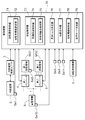
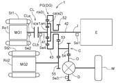
- FIG. 1 is a schematic diagram showing a system configuration of a vehicle drive device according to a first embodiment of the present invention. It is a velocity diagram for demonstrating operation
- the vehicle drive device 1 is a drive for driving a vehicle (hybrid vehicle) that includes both an internal combustion engine E and rotating electrical machines MG1 and MG2 as wheel driving force sources. It is considered as a device (drive device for a hybrid vehicle).
- the vehicle drive device 1 which concerns on this embodiment is provided with the control apparatus 70 (refer FIG. 2), and this control apparatus 70 is operation
- a broken line indicates a power transmission path
- a solid arrow indicates a transmission path for various information.
- the differential gear device DG provided in the vehicle drive device 1 is constituted by a planetary gear mechanism PG having a sun gear s, a carrier ca, and a ring gear r as rotating elements.
- the first rotating electrical machine MG1 is drivingly connected to the sun gear s
- the input member I is drivingly connected to the carrier ca
- the second rotating electrical machine MG2 and the ring gear r are not connected to the other rotating elements of the planetary gear mechanism PG.
- the output member O is drivingly connected.
- the input member I is drivingly connected to the internal combustion engine E
- the output member O is drivingly connected to the wheels W.
- the vehicle drive device 1 includes a frictional engagement device CL that can release the drive connection between the input member I and the carrier ca.
- driving connection is released refers to a state of connection between two rotational elements that are drivingly connected, a state in which no driving force is transmitted between the two rotational elements (non-connected state). Means to.
- the internal combustion engine E is The energy efficiency can be improved by avoiding idling (dragging) of the first rotating electrical machine MG1, and driving of an auxiliary machine (for example, an oil pump) using the rotation of the carrier ca is possible.
- an auxiliary machine for example, an oil pump
- the vehicle drive device 1 includes an input member I that is drivingly connected to the internal combustion engine E, an output member O that is drivingly connected to the wheels W, a first rotating electrical machine MG1, a second rotating electrical machine MG2, and at least three rotations.
- a differential gear device DG having elements and a control device 70 are provided.
- the vehicle drive device 1 according to the present embodiment distributes the output torque of the internal combustion engine E to the first rotating electrical machine MG1 side and the wheels W and the second rotating electrical machine MG2 side. It is configured as a drive device for a so-called two-motor split type hybrid vehicle including the device DG.
- the differential gear device DG is constituted by a single pinion type planetary gear mechanism PG. That is, the differential gear device DG has three rotating elements in this example. Then, when these three rotating elements are designated as the first rotating element e1, the second rotating element e2, and the third rotating element e3 in the order of the rotation speed (that is, the arrangement order in the speed diagram (collinear diagram)),
- the sun gear s of the planetary gear mechanism PG constitutes the first rotating element e1
- the carrier ca of the planetary gear mechanism PG constitutes the second rotating element e2
- the ring gear r of the planetary gear mechanism PG rotates third.
- Element e3 is configured.
- the vehicle drive device 1 includes a friction engagement device CL capable of releasing the drive connection between any one of the input member I, the output member O, and the first rotating electrical machine MG1 and the rotation element of the differential gear device DG. ing.
- a rotating element connecting member that rotates integrally with the rotating element is connected to each rotating element of the differential gear device DG.
- a first rotating element connecting member 41 is connected to the sun gear s as the first rotating element e1
- a second rotation is connected to the carrier ca as the second rotating element e2.
- the element connecting member 42 is connected, and the third rotating element connecting member 43 is connected to the ring gear r as the third rotating element e3.
- each of the input member I, the output member O, the first rotating electrical machine MG1, and the second rotating electrical machine MG2 is drivingly connected to any of these rotating element connecting members, so that any of the differential gear devices DG It is drivingly connected to the rotating element.
- the input member I is drivingly connected to the internal combustion engine E.
- the input member I is a shaft member (input shaft).
- the internal combustion engine E is a prime mover that outputs power by combustion of fuel.
- a spark ignition engine such as a gasoline engine or a compression ignition engine such as a diesel engine can be used.
- the input member I is drivingly connected to an output shaft of an internal combustion engine such as a crankshaft of the internal combustion engine E.
- the input member I is drivingly connected so as to rotate integrally with the output shaft of the internal combustion engine, and the rotational speed of the input member I becomes equal to the rotational speed of the internal combustion engine E.
- the internal combustion engine E is drivingly connected to the input member I via another device such as a damper or a flywheel.
- the output member O is drivingly connected to the wheel W.
- the output member O is a gear member, and specifically, a differential input gear provided in the output differential gear device D.
- the output differential gear device D is configured by a differential gear mechanism using a plurality of bevel gears that mesh with each other, and the torque transmitted to the output member O is applied to the left and right wheels W that serve as drive wheels. Distribute.
- the first rotating electrical machine MG1 has a first stator St1 fixed to a case (not shown) and a first rotor Ro1 that is rotatably supported on the radially inner side of the first stator St1.
- the second rotating electrical machine MG2 includes a second stator St2 fixed to a case (not shown) and a second rotor Ro2 that is rotatably supported on the radially inner side of the second stator St2.
- the second rotor Ro2 is drivingly connected to rotate integrally with the second rotating electrical machine output gear 55 via a second rotor shaft to which the second rotor Ro2 is fixed.
- the first rotating electrical machine MG1 is electrically connected to the power storage device B via the first inverter 4, and the second rotating electrical machine MG2 is connected to the power storage device B via the second inverter 5. Is electrically connected.
- the power storage device B various known power storage devices such as a battery and a capacitor can be used.
- each of the first rotating electrical machine MG1 and the second rotating electrical machine MG2 has a function as a motor (electric motor) that receives power supplied from the power storage device B and generates power (torque), It is possible to function as a generator (generator) that receives supply to generate electric power and supplies the generated electric power to the power storage device B.
- the friction engagement device CL includes two engagement members, and a member that is drivingly connected to a first engagement member CLa that is one engagement member and a second engagement member CLb that is the other engagement member.
- This is a device for selectively driving and connecting the members that are drivingly connected.
- the friction engagement device CL is configured as a wet multi-plate clutch that operates by hydraulic pressure.
- the friction engagement device CL is provided so as to be able to release the drive connection between the input member I and the rotation element (second rotation element e2 in this example) of the differential gear device DG. That is, in this embodiment, the friction engagement device CL is provided in the power transmission path between the input member I and the rotation element (second rotation element e2 in this example) of the differential gear device DG.
- the first engagement member CLa is an input side engagement member that is drivingly connected so as to rotate integrally with the input member I, and the second engagement member CLb rotates integrally with the second rotation element connection member 42.
- the output side engaging member is drive-connected.
- the first rotating electrical machine MG1 is connected to the sun gear s (first rotating element e1) without passing through other rotating elements of the planetary gear mechanism PG (differential gear device DG).
- the input member I is drivingly connected to the carrier ca (second rotating element e2)
- the second rotating electrical machine MG2 and the output member O are drivingly connected to the ring gear r (third rotating element e3).
- the second rotating electrical machine MG2 is connected to the ring gear r (third rotating element e3), which is the rotating element of the differential gear device DG to which the output member O is drivingly connected, with the differential gear device DG. Drive-connected without any other rotating element.
- the first rotating electrical machine MG1 is drivingly connected to the sun gear s by drivingly connecting the first rotor shaft to which the first rotor Ro1 is fixed so as to rotate integrally with the first rotating element connecting member 41. ing. That is, in the present embodiment, the rotational speed of the sun gear s (first rotating element e1) is always equal to the rotational speed of the first rotor Ro1 (first rotating electrical machine MG1).
- the input member I is selectively connected to the carrier ca via the friction engagement device CL by being driven and connected to the first engagement member CLa of the friction engagement device CL so as to rotate integrally.
- “selectively drive-coupled” means that a state in which a driving force is transmitted between two rotational elements that are drive-coupled is selectively realized. That is, in the present embodiment, when the friction engagement device CL is in the direct engagement state, the rotation speed of the carrier ca (second rotation element e2) is equal to the rotation speed of the input member I (internal combustion engine E). Become. In the present embodiment, the rotational speed difference between the two engaging members of the frictional engagement device CL is such that the rotational speed of the input member I (internal combustion engine E) and the carrier ca (second rotating element connecting member 42). It becomes the difference with the rotation speed.
- the second rotating electrical machine MG2 and the output member O are drivingly connected to the ring gear r via the counter gear mechanism C.
- the counter gear mechanism C includes a first counter gear 53, a second counter gear 54, and a counter shaft that is coupled so as to rotate integrally.
- the third rotating element connecting member 43 has a counter drive gear 52 that meshes with the first counter gear 53.
- the second rotating electrical machine output gear 55 is arranged so as to mesh with the first counter gear 53 at a position different from the counter drive gear 52 in the circumferential direction (the circumferential direction of the first counter gear 53).
- the electric machine MG2 is drivingly connected to the ring gear r.
- the output member O is disposed so as to mesh with the second counter gear 54, so that it is drivingly connected to the ring gear r. That is, in the present embodiment, the rotational speed relationships among the ring gear r, the second rotating electrical machine MG2 and the output member O are proportional to each other, and the proportionality coefficient (that is, the rotational speed ratio) is interposed therebetween. It becomes a value according to the number of teeth of the gear to be operated.
- the vehicle drive device 1 includes a hybrid travel mode (split travel mode) in which the vehicle is driven by the output torques of both the internal combustion engine E and the rotary electric machines MG1, MG2, and the rotary electric machine MG1, An electric travel mode (EV travel mode) that travels only by the output torque of MG2 (in this example, only the second rotating electrical machine MG2) is provided.
- a hybrid travel mode split travel mode
- EV travel mode electric travel mode that travels only by the output torque of MG2 (in this example, only the second rotating electrical machine MG2) is provided.
- the friction engagement device CL is brought into the direct engagement state, and the output torque of the internal combustion engine E is applied to the sun gear s (first rotating electrical machine MG1) and the ring gear r (counter drive gear 52) by the planetary gear mechanism PG. It becomes a state to be distributed.
- the friction engagement device CL is released and the internal combustion engine E is stopped. Further, the rotational speed of the internal combustion engine output shaft (input member I) is basically zero due to the internal friction force of the internal combustion engine E, and the rotational speed of the first rotating electrical machine MG1 is basically controlled to be zero. Is done.
- the control device 70 includes a travel mode determination unit 79, a rotating electrical machine control unit 78, a rotation speed control unit 71, an engagement control unit 73, a required torque determination unit 76, and a start command.
- a portion 77 is provided.
- the control device 70 includes an arithmetic processing device such as a CPU as a core, and includes a storage device such as a RAM and a ROM. Each functional unit of the control device 70 is configured by software (program) stored in a ROM or the like, hardware such as a separately provided arithmetic circuit, or both. Each of these functional units is configured to exchange information with each other.
- the control device 70 is configured to be able to acquire information from a sensor or the like provided in each part of the vehicle in order to acquire information of each part of the vehicle on which the vehicle drive device 1 is mounted.
- the control device 70 includes an input member sensor Se1, an output member sensor Se3, an accelerator opening sensor Se11, a first rotor shaft sensor Se2, a release target rotation element sensor Se4, and a storage state. Information from the sensor Se10 can be acquired.
- the input member sensor Se1 is a sensor that detects the rotational speed of the input member I.
- the rotational speed of the input member I detected by the input member sensor Se1 is equal to the rotational speed of the internal combustion engine E in this example.
- the output member sensor Se3 is a sensor that detects the rotation speed of the output member O.
- the control device 70 derives the vehicle speed based on the rotational speed of the output member O detected by the output member sensor Se3.
- the accelerator opening sensor Se11 is a sensor that detects the accelerator opening by detecting an operation amount of an accelerator pedal (not shown).
- the first rotor shaft sensor Se2 is a sensor that detects the rotational speed of the first rotating electrical machine MG1 (first rotor shaft). In this example, the rotation of the first rotating electrical machine MG1 detected by the first rotor shaft sensor Se2. The speed is equal to the rotational speed of the first rotating element connecting member 41 (sun gear s).
- the first rotor shaft sensor Se2 can be, for example, a rotation sensor (such as a resolver) provided in the first rotating electrical machine MG1.
- the release target rotation element sensor Se4 is a sensor that detects the rotational speed of the release target rotation element en among the rotation elements of the differential gear device DG.
- the release target rotation element en is a rotation element that can be released from the driving connection with any of the input member I, the output member O, and the first rotating electrical machine MG1 by the friction engagement device CL.
- the carrier ca is the release target rotation element en
- the release target rotation element sensor Se4 detects the rotation speed of the second rotation element connecting member 42.
- the power storage state sensor Se10 is a sensor that detects the state of the power storage device B (in this example, temperature and amount of power storage).
- the storage state sensor Se10 includes a voltage sensor, a current sensor, and the like, and detects the amount of storage by detecting SOC (state of charge).
- the power storage state sensor Se10 includes a temperature sensor and detects the temperature of the power storage device B.
- the vehicle is provided with an internal combustion engine control unit 3.
- the internal combustion engine control unit 3 controls the operation of the internal combustion engine E by controlling each part of the internal combustion engine E. Specifically, the internal combustion engine control unit 3 sets a target torque and a target rotational speed as control targets for the output torque and rotational speed of the internal combustion engine E, and operates the internal combustion engine E according to the control target. Then, the operation control of the internal combustion engine E is performed.
- the target torque and the target rotation speed are set based on a command from the control device 70. Further, when the internal combustion engine control unit 3 receives a start command from the control device 70 while the internal combustion engine E is stopped, the internal combustion engine control unit 3 starts fuel injection and ignition, and changes the internal combustion engine E to the start state. Further, when the internal combustion engine control unit 3 receives a stop command from the control device 70 in the start state of the internal combustion engine E, the internal combustion engine control unit 3 stops the fuel injection and ignition and changes the internal combustion engine E to the stop state. .
- the travel mode determination unit 79 is a functional unit that determines the travel mode of the vehicle.
- the traveling mode determination unit 79 for example, the vehicle speed derived based on the detection result of the output member sensor Se3, the accelerator opening detected by the accelerator opening sensor Se11, and the storage state (storage) detected by the storage state sensor Se10.
- the travel mode to be realized by the vehicle drive device 1 is determined based on the amount, temperature, and the like.
- the driving modes that can be determined by the driving mode determination unit 79 include an electric driving mode and a hybrid driving mode.
- the driving mode determination part 79 is a mode that prescribes the relationship between the vehicle speed, the accelerator opening, the storage state, and the driving mode, which is basically stored in a storage device composed of a memory or the like.
- a travel mode is determined with reference to a selection map (not shown).
- the internal combustion engine start condition is a condition for starting the internal combustion engine E in a stopped state, and is satisfied when the vehicle is in a situation that requires the torque of the internal combustion engine E. For example, when the driver strongly depresses the accelerator pedal while the vehicle is stopped or in the electric travel mode, the torque required for the vehicle cannot be obtained with only the rotating electrical machines MG1 and MG2.
- the internal combustion engine start condition is established.
- the rotating electric machine control unit 78 is a functional unit that performs operation control of the first rotating electric machine MG1 and the second rotating electric machine MG2. Specifically, the rotating electrical machine control unit 78 sets a target torque and a target rotational speed as control targets for the output torque and rotational speed of the first rotating electrical machine MG1, and the first rotating electrical machine MG1 is set according to this control target.
- the first inverter 4 is controlled so as to operate.
- the rotating electrical machine control unit 78 controls the operation of the first rotating electrical machine MG1 by torque control or rotational speed control.
- the torque control is a control in which a target torque for the first rotating electrical machine MG1 is set and the output torque of the first rotating electrical machine MG1 is brought close to (follows) the target torque.
- the rotational speed control sets a target rotational speed for the first rotating electrical machine MG1, controls the output torque of the first rotating electrical machine MG1, and brings the rotational speed of the first rotating electrical machine MG1 closer to (follows) the target rotational speed.
- the control for the second rotating electrical machine MG2 is the same as that for the first rotating electrical machine MG1 except that the first inverter 4 is replaced with the second inverter 5.
- the requested torque determining unit 76 is a functional unit that determines the vehicle required torque.
- the vehicle required torque is a torque required from the vehicle side to the driving force source (in this example, the internal combustion engine E and the rotating electrical machines MG1, MG2), and is manually operated by the driver (for example, an accelerator operation). Torque necessary for realizing the behavior according to the vehicle, torque required for maintaining the running performance of the vehicle (for example, torque for charging the power storage device B), and the like. That is, the vehicle required torque is a torque required to drive the vehicle.
- the required torque determination unit 76 determines a predetermined value based on the vehicle speed derived based on the detection result of the output member sensor Se3 (rotational speed of the output member O) and the detection result of the accelerator opening sensor Se11 (accelerator opening). The vehicle required torque is determined by referring to a map (not shown). The required torque determining unit 76 determines the vehicle required torque based on the power storage state of the power storage device B detected by the power storage state sensor Se10 in addition to the vehicle speed and the accelerator opening as necessary. .
- the required torque determining unit 76 determines the internal combustion engine required torque based on the vehicle required torque, and outputs information on the internal combustion engine required torque to the internal combustion engine control unit 3.
- the internal combustion engine required torque is a torque required for the internal combustion engine E, in other words, an output torque required for the internal combustion engine E to run the vehicle. Then, the internal combustion engine control unit 3 sets a target torque and a target rotation speed for the internal combustion engine E based on the internal combustion engine required torque, and controls the operation of the internal combustion engine E.
- the required torque determining unit 76 determines the first rotating electrical machine required torque and the second rotating electrical machine required torque based on the vehicle required torque, and rotates the information on the first rotating electrical machine required torque and the second rotating electrical machine required torque. Output to the electric machine control unit 78.
- the first rotating electrical machine required torque is a torque required for the first rotating electrical machine MG1, in other words, an output torque required for the first rotating electrical machine MG1 to run the vehicle.
- the second rotating electrical machine required torque is a torque required for the second rotating electrical machine MG2, in other words, an output torque required for the second rotating electrical machine MG2 to run the vehicle.
- the rotating electrical machine control unit 78 sets a target torque and a target rotational speed for the first rotating electrical machine MG1 and the second rotating electrical machine MG2 based on the first rotating electrical machine required torque and the second rotating electrical machine required torque, The first rotating electrical machine MG1 and the second rotating electrical machine MG2 are controlled.
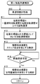
- Rotational speed control unit 71 starts internal combustion engine E from a state in which friction engagement device CL is in a released state and internal combustion engine E is stopped (hereinafter referred to as a “release stop state”). Is a functional unit that performs rotation speed control for making the rotation speed of the first rotating electrical machine MG1 coincide with the start target value Ni when the internal combustion engine start condition is satisfied. For example, when the travel mode determination unit 79 determines to switch to the hybrid travel mode during travel in the electric travel mode, the rotational speed control unit 71 executes rotational speed control.
- the rotation speed control by the rotation speed control unit 71 is executed via the rotating electrical machine control unit 78.
- the rotating electrical machine control unit 78 sets the starting target value Ni to the target rotational speed, and calculates the target rotational speed and the actual rotational speed of the first rotating electrical machine MG1 detected by the first rotor shaft sensor Se2. Based on the difference, the rotational speed control of the first rotating electrical machine MG1 is executed by the rotational speed feedback control.
- the starting target value Ni is a target value for the rotational speed of the first rotating electrical machine MG1 when the rotational speed control is executed, and is set by the starting target value setting unit 72 provided in the rotational speed control unit 71.
- the configuration of the starting target value setting unit 72 will be described later in “1-2-8. Configuration of the starting target value setting unit”.
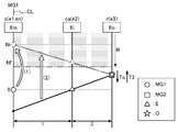
- FIG. 3 is a velocity diagram showing the operating state of the differential gear device DG (the planetary gear mechanism PG in this example).
- the vertical axis corresponds to the rotational speed of each rotating element. That is, “0” described corresponding to the vertical axis indicates that the rotation speed is zero, the upper side is positive rotation (rotation speed is positive), and the lower side is negative rotation (rotation speed is negative). It is.
- each of the plurality of vertical lines arranged in parallel corresponds to each rotation element of the differential gear device DG.
- the interval between the vertical lines corresponding to each rotating element corresponds to the gear ratio ⁇ of the differential gear device DG.
- the differential gear device DG is configured by a planetary gear mechanism PG, and the gear ratio ⁇ is the gear ratio between the sun gear s and the ring gear r.
- “Em”, “Ei”, and “Eo” surrounded by a rectangle described above each vertical line are a reaction force transmission element Em, an input rotation element Ei, The output rotation element Eo is shown.
- the rotational speed of the first rotating electrical machine MG1, the rotational speed of the second rotating electrical machine MG2, the rotational speed of the internal combustion engine E (input member I), and the rotational speed of the output member O are mutually different. Shown with different symbols.
- the rotational speeds of the first rotating electrical machine MG1, the second rotating electrical machine MG2, the internal combustion engine E, and the output member O are the rotational elements (rotating elements) of the differential gear device DG.
- Rotational speed after conversion (shift) by a transmission member (excluding the engagement element that selectively transmits rotation and torque, such as the friction engagement device CL) provided in the power transmission path to the connecting member) Represents.
- the description relating to the rotation speed of each member in the following description basically means the rotation speed after conversion of the rotation speed by the transmission member.
- the first rotating electrical machine MG1 since the first rotating electrical machine MG1 is drivingly coupled so as to rotate integrally with the first rotating element coupling member 41, the first rotating electrical machine MG1 (sun gear s on the speed diagram). ) Matches the actual rotation speed of the first rotating electrical machine MG1. Further, the internal combustion engine E (input member I) rotates at the same rotational speed as that of the second rotating element connecting member 42 when the friction engagement device CL is in the direct engagement state, and therefore the internal combustion engine on the speed diagram. The rotational speed of the engine E (carrier ca) matches the actual rotational speed of the internal combustion engine E.
- the rotational speed of the second rotating electrical machine MG2 (ring gear r) on the speed diagram is The actual rotational speed of the second rotating electrical machine MG2 is multiplied by the gear ratio of the power transmission system including the second rotating electrical machine output gear 55, the first counter gear 53, and the counter drive gear 52.
- the output member O is also drivingly connected to the third rotating element connecting member 43 via the counter gear mechanism C, the rotational speed of the output member O on the speed diagram is the actual rotational speed of the output member O.
- a gear ratio of a power transmission system composed of a differential input gear (output member O), a second counter gear 54, a first counter gear 53, and a counter drive gear 52.
- T2 indicates the torque (second rotating electrical machine torque) transmitted from the second rotating electrical machine MG2 to the rotating element (ring gear r in this example) of the differential gear device DG
- To indicates the output member O ( The torque (running torque, running resistance) transmitted from the wheel W) to the rotating element (ring gear r in this example) of the differential gear device DG is shown.
- the downward arrow represents the torque in the negative direction.
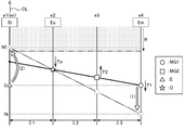
- Each speed diagram referred to below also shows the operating state of the differential gear device DG, as in FIG. Moreover, in FIG. 17 etc. referred later, "T1" has shown the torque (1st rotary electric machine torque) transmitted to the rotation element of 1st rotary electric machine MG1 to the differential gear apparatus DG.
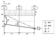
- the solid line indicates the operation in the electric travel mode in which the friction engagement device CL is in the released state and travels only by the output torque of the rotating electrical machines MG1 and MG2 (in this example, only the second rotating electrical machine MG2).
- the second rotating electrical machine MG2 is controlled to output the second rotating electrical machine torque T2 corresponding to the vehicle required torque determined based on the vehicle speed, the accelerator opening, and the like.
- torque for accelerating or cruising the vehicle is required, and the second rotating electrical machine MG2 is powered while rotating in the positive direction against the traveling torque To acting on the ring gear r in the negative direction.
- the case where the second rotating electrical machine torque T2 in the positive direction is output is illustrated.
- the friction engagement device CL In the electric travel mode, the friction engagement device CL is released, and the release target rotating element en of the differential gear device DG is freely rotatable.
- the release target rotating element en is the carrier ca, and the friction engagement device CL is provided in the power transmission path between the carrier ca and the internal combustion engine E. Therefore, in the electric travel mode, the carrier ca and the internal combustion engine E are disconnected from each other (disconnected state), so that the internal combustion engine E is disconnected from the carrier ca and the carrier ca can freely rotate.
- the present embodiment as shown by a solid line in FIG.
- the rotation speed of the first rotating electrical machine MG1 is basically zero, and the carrier ca has a rotation speed of the ring gear r determined according to the vehicle speed, It rotates at a rotational speed determined based on the rotational speed of the sun gear s determined according to the rotational speed of the first rotating electrical machine MG1.
- the rotational speed control is executed by the rotational speed control unit 71, and the rotational speed of the first rotating electrical machine MG1 matches the start target value Ni. (The process indicated by the arrow “(1)” in FIG. 3). That is, the rotational speed control unit 71 changes the rotational speed of the first rotating electrical machine MG1 using the starting target value Ni as a target value.
- the starting target value Ni is higher than the rotation speed (zero in this example) of the first rotating electrical machine MG1 when the electric travel mode is executed, so the first rotating electrical machine MG1 generates a torque in the positive direction. Output to increase the rotation speed.
- the rotational speed of the carrier ca to which the internal combustion engine E is drivingly connected when the friction engagement device CL is engaged also increases.
- “increase” in the rotational speed means that the rotational speed is changed in the positive direction
- “decrease” in the rotational speed means that the rotational speed is changed in the negative direction.
- the engagement control unit 73 performs the engagement process of the friction engagement device CL in a state where the rotation speed of the first rotating electrical machine MG1 has reached the start target value Ni. Then, on the condition that the friction engagement device CL is in the direct engagement state, the internal combustion engine E is instructed to start.
- the target rotational speed for example, the rotational speed of the first rotating electrical machine MG1
- target rotational speed the rotational speed of the first rotating electrical machine MG1
- the rotational speed of the output member O is the same as the rotational speed of the internal combustion engine E. Similarly, the direction is positive.
- the process indicated by “(1) arrow” represents the rotational speed control by the rotational speed controller 71.
- the starting target value Ni is lower than the rotational speed (zero in this example) of the first rotating electrical machine MG1 when the electric travel mode is executed.
- the electric machine MG1 outputs a torque in the negative direction to reduce the rotation speed, and accordingly, the rotation speed of the carrier ca to which the internal combustion engine E is drivingly connected is also reduced when the friction engagement device CL is engaged.
- the engagement control unit 73 is a functional unit that controls the operation of the friction engagement device CL.
- the engagement control unit 73 controls the operation of the friction engagement device CL by controlling the hydraulic pressure (supply pressure to the friction engagement device CL) supplied to the friction engagement device CL via the hydraulic control device 2. Do. Specifically, the engagement control unit 73 generates a hydraulic pressure command value for the friction engagement device CL, and the hydraulic pressure control device 2 supplies a hydraulic pressure corresponding to the hydraulic pressure command value to the friction engagement device CL.
- the state of engagement between the two engagement members of the friction engagement device CL includes a “released state” in which rotation and torque are not transmitted between the two engagement members, and the two engagements.
- a “slip engagement state” in which the members engage with each other with a rotational speed difference
- a “direct engagement state” in which the two engagement members engage with each other in an integrally rotating state. That is, the “slip engagement state” is an engagement state in which torque is transmitted between the two engagement members in a state where the two engagement members of the friction engagement device CL rotate relative to each other.
- the “directly engaged state” is an engaged state in which the two engaging members of the friction engagement device CL are directly connected and there is no differential rotation between the two engaging members.
- the magnitude of torque that can be transmitted between the two engagement members by the friction engagement device CL is determined according to the engagement pressure of the friction engagement device CL at that time.
- the magnitude of the torque at this time is defined as the transmission torque capacity of the friction engagement device CL.
- frictional engagement is achieved by continuously controlling the amount of oil supplied to the frictional engagement device CL and the magnitude of the supply pressure with a proportional solenoid valve in accordance with the hydraulic pressure command value for the frictional engagement device CL.
- the increase / decrease of the transmission torque capacity of the device CL can be continuously controlled.
- the engagement control unit 73 controls the operation of the friction engagement device CL by torque control or rotation speed control.
- torque control a target transmission torque capacity is set for the friction engagement device CL, and the hydraulic pressure command value is set so that the transmission torque capacity of the friction engagement device CL approaches (follows) the target transmission torque capacity. It is the control which produces
- rotational speed control sets the target differential rotational speed for the friction engagement device CL, and makes the rotational speed difference between the two engaging members approach (follow) the target differential rotational speed. This is control for generating a command value.
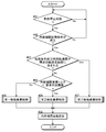
- the engagement control unit 73 includes a synchronous engagement control unit 74 and an asynchronous engagement control unit 75. Then, the engagement control unit 73 executes the engagement control of the friction engagement device CL by the synchronous engagement control unit 74 or the asynchronous engagement control unit 75 on condition that the rotation speed control by the rotation speed control unit 71 is executed. Then, the friction engagement device CL in the released state is changed to the direct engagement state.
- the synchronous engagement control unit 74 is a functional unit that performs synchronous engagement control that starts the engagement of the friction engagement device CL in a synchronized state and engages the friction engagement device CL.
- the synchronized state is a state in which a difference in rotational speed between two target rotating members (here, two engaging members of the friction engagement device CL) is less than a differential rotation threshold.
- This synchronized state includes a state where the rotational speed of one or both of the rotating members is zero.
- the state where the rotational speed difference between the two target rotating members is equal to or greater than the differential rotation threshold is an asynchronous state.
- This differential rotation threshold is a predetermined threshold set in advance, and can be set to a value of, for example, 10 rpm to 100 rpm.
- the synchronous engagement control unit 74 sends a hydraulic pressure command value for the friction engagement device CL to the friction engagement device CL in order to change the friction engagement device CL from the released state to the direct engagement state. Control is performed so that the transmission torque capacity increases at a predetermined rate of change (for example, a constant rate of change) from zero to a value (hereinafter, referred to as a “steady direct connection value”) that is in a steady direct connection state.
- a predetermined rate of change for example, a constant rate of change
- the change rate is set to a relatively large value
- the friction engagement device CL is set in a relatively short time. Is increased to a steady direct coupling engagement value.
- the hydraulic pressure for setting the transmission torque capacity of the friction engagement device CL to the steady direct engagement value is “steady hydraulic pressure”
- the hydraulic pressure command value for the friction engagement device CL is reduced to the steady hydraulic pressure in a relatively short time. Raise.
- the “steady direct coupling engagement state” means a state in which the direct coupling engagement state is maintained regardless of a change in torque transmitted by the friction engagement device CL.
- the steady hydraulic pressure for obtaining such a steady direct engagement state is, for example, a line pressure generated by the hydraulic control device 2.
- the asynchronous engagement control unit 75 is a functional unit that performs asynchronous engagement control for starting the engagement of the friction engagement device CL in an asynchronous state and engaging the friction engagement device CL.
- the process indicated by “arrow (2)” represents the asynchronous engagement control
- the process indicated by “arrow (1)” is shown.
- Asynchronous engagement control is shown.
- the asynchronous engagement control unit 75 reduces the rotational speed difference between the two engagement members of the friction engagement device CL in the slip engagement state, and is directly connected on the condition that the synchronization state is achieved. Execute the control to be in the combined state.
- the asynchronous engagement control unit 75 sends the hydraulic command value for the friction engagement device CL to the transmission torque of the friction engagement device CL in order to change the friction engagement device CL from the released state to the slip engagement state.
- Control is performed so that the capacity increases from zero at a predetermined change rate (for example, a constant change rate).
- a predetermined change rate for example, a constant change rate.
- the change rate of the transmission torque capacity is set to a smaller value than in the case of the synchronous engagement control. The That is, in the asynchronous engagement control, the transmission torque capacity of the friction engagement device CL is increased over time than the synchronous engagement control.
- the asynchronous engagement control unit 75 keeps the transmission torque capacity of the friction engagement device CL at the value at that time.
- the hydraulic pressure command value for the friction engagement device CL is controlled. Thereby, the friction engagement device CL is maintained in the slip engagement state.
- the asynchronous engagement control unit 75 uses a preset target transmission torque capacity for slip engagement, and controls the hydraulic pressure command value so that the transmission torque capacity is held at the target transmission torque capacity, whereby friction is achieved. It can also be set as the structure which maintains the engagement apparatus CL in a slip engagement state.
- the asynchronous engagement control unit 75 Controls the hydraulic pressure command value for the friction engagement device CL so as to change the friction engagement device CL from the slip engagement state to the direct engagement state.
- the asynchronous engagement control unit 75 maintains the transmission torque capacity in the slip engagement state even after the two engagement members of the friction engagement device CL are in the synchronized state, so that the friction engagement is achieved.
- the device CL is brought into a direct coupling engagement state.
- the asynchronous engagement control unit 75 changes the hydraulic pressure command value for the frictional engagement device CL to the above-described steady hydraulic pressure at a predetermined change rate (for example, a constant change rate). Control to ascend. As a result, the transmission torque capacity of the friction engagement device CL increases to a steady direct engagement value at a predetermined change rate (for example, a constant change rate), and the friction engagement device enters a steady direct engagement state.
- a predetermined change rate for example, a constant change rate
- the rotating electrical machine control unit 78 sets the rotational speed of the first rotating electrical machine MG1 to the rotational speed of the rotational speed control unit 71 until the frictional engagement device CL is in the direct engagement state by executing the asynchronous engagement control.
- Rotational speed control (rotational speed feedback control in this example) is executed so as to maintain the rotational speed reached by speed control (that is, the starting target value Ni).
- the input member I internal combustion engine E
- the second rotation element e2 carrier ca
- the rotation speed of the carrier ca is uniquely determined according to the vehicle speed and the rotation speed of the first rotating electrical machine MG1, if the vehicle speed is constant during the asynchronous engagement control, the rotation speed of the carrier ca is also It is maintained at a constant value.
- the rotation speed of the internal combustion engine E increases toward the rotation speed of the carrier ca (the process indicated by “arrow (2)” in FIG. 3, the arrow “(1)” in FIG. 5.
- the rotational speed of the internal combustion engine E becomes equal to the rotational speed of the carrier ca.
- the first rotating electrical machine MG1 outputs its torque in the positive direction to maintain its own rotational speed at the start target value Ni.
- the rotary electric machine control unit 78 starts the engagement of the friction engagement device CL, and the output torque of the first rotary electric machine MG1 transmitted to the wheels W via the ring gear r and the load torque caused by the internal combustion engine E.
- the control for correcting the output torque of the second rotating electrical machine MG2 is executed so as to cancel out.
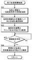
- the start command unit 77 is provided on the condition that the friction engagement device CL is in the direct engagement state and that the rotation speed of the internal combustion engine E becomes a start rotation speed Nf (described later). It is a functional part which commands the start. As described above, the vehicle is provided with the internal combustion engine control unit 3 that controls the operation of the internal combustion engine E, and the start command unit 77 commands the internal combustion engine control unit 3 to start the internal combustion engine E. Then, the internal combustion engine E is started. In the following, the control to be performed after the internal combustion engine start condition is satisfied and the friction engagement device CL is brought into the direct engagement state and the rotation speed of the internal combustion engine E is set to the start rotation speed Nf is referred to as “start preparation”. It is called “control”. The start preparation control is executed with the rotation speed control unit 71 and the engagement control unit 73 as the core.
- the rotational speed of the internal combustion engine E needs to be a rotational speed at which ignition is possible. That is, if the range of the rotational speed at which the internal combustion engine can be started is the startable rotational speed range R, the rotational speed at the start of the internal combustion engine E needs to be a value within the startable rotational speed range R.
- the startable rotation speed range R is a range having a lower limit value as shown in FIG. 3, and the target value of the rotation speed of the internal combustion engine E for starting the internal combustion engine E is within the startable rotation speed range R.
- the starting rotational speed Nf is set. Note that the lower limit value of the startable rotation speed range R is set to, for example, the idle rotation speed of the internal combustion engine E.
- the starting rotational speed Nf can be set to any value within the startable rotational speed range R.
- the starting rotational speed Nf can be set to a lower limit value of the startable rotational speed range R or a value higher than the lower limit value by a predetermined rotational speed.
- the predetermined rotation speed can be a rotation speed determined from 50 to 500 rpm, for example.
- the starting rotational speed Nf is a rotational speed within the startable rotational speed range R, and the internal combustion engine E can output the required torque. It can also be set to speed.
- the rotation speed having the lowest fuel consumption rate (good fuel consumption) among the rotation speeds that can output the internal combustion engine required torque included in the startable rotation speed range R is set as the start rotation speed Nf. Can do.
- the start target value setting unit 72 is a functional unit that sets the start target value Ni.
- the starting target value Ni is a target value of the rotational speed of the first rotating electrical machine MG1 when the rotational speed control by the rotational speed control unit 71 is executed as described above.
- the start target value setting unit 72 sets the start target value Ni when the internal combustion engine start condition is satisfied in the release stop state.
- the start target value setting unit 72 is first based on the rotation speed of the first rotating electrical machine MG1 when the internal combustion engine start condition is satisfied (hereinafter referred to as “rotation speed when the start condition is satisfied”). Then, it is determined whether or not the rotation speed when the start condition is satisfied is included in the specific rotation speed range.
- the specific rotation speed range is referred to as a rotation speed of the internal combustion engine E (hereinafter referred to as “direct rotation speed”) when the friction engagement device CL is in a direct engagement state under the control of the engagement control unit 73.
- the rotating element to which the first rotating electrical machine MG1 is drivingly connected rotates at the rotation speed when the start condition of the first rotating electrical machine MG1 is satisfied, and the rotating element to which the output member O is driven is connected to start the internal combustion engine.
- the rotation speed of the rotary element to which the internal combustion engine E is drivingly connected is assumed to be equal to or higher than the lower limit value of the startable rotation speed range R when the rotation is performed at the rotation speed of the output member O when the condition is satisfied.
- the rotation speed when the start condition is satisfied is included in the specific rotation speed range.
- the internal combustion engine E is drivingly connected to the carrier ca via the friction engagement device CL, and the rotation speed of the internal combustion engine E is equal to the rotation speed of the carrier ca in the direct engagement state. Therefore, in this embodiment, if the rotation speed of the carrier ca when the internal combustion engine start condition is satisfied is equal to or greater than the lower limit value of the startable rotation speed range R, the rotation speed when the start condition is satisfied of the first rotating electrical machine MG1 is the specific rotation. Included in the speed range. 3 to 5, the state indicated by the solid line represents the state when the internal combustion engine start condition is satisfied. Therefore, in the examples shown in FIGS. 3 and 4, the rotation speed of the carrier ca when the start condition is satisfied is the startable rotation.
- the rotation speed of the carrier ca when the start condition is satisfied is equal to or higher than the lower limit value of the startable rotation speed range R, and the rotation speed when the start condition is satisfied is included in the specific rotation speed range.
- the rotational speed of the sun gear s when the internal combustion engine start condition is satisfied is acquired based on detection information of the first rotor shaft sensor Se2 (essentially zero in this example), and when the internal combustion engine start condition is satisfied.
- the rotational speed of the ring gear r is acquired based on the detection information of the output member sensor Se3. Since the rotational speed of the ring gear r is proportional to the rotational speed of the second rotating electrical machine MG2, the rotational speed of the ring gear r is based on the detection result of a rotation sensor (such as a resolver) provided in the second rotating electrical machine MG2. It can also be set as the structure acquired.
- the start target value setting unit 72 further determines the required internal combustion engine torque when the rotation speed when the start condition is satisfied is not included in the specific rotation speed range. It is determined whether or not the request determination threshold is exceeded.
- the request determination threshold is a threshold for determining the magnitude of the internal combustion engine required torque, and can be an arbitrary value.
- the request determination threshold value can be a fixed value or a variable value. For example, when the driver can select the driving mode of the vehicle (for example, eco mode, sports mode, etc.), the request determination threshold value can be variably set to a different value depending on the driving mode. . In such a configuration, when the driver selects a driving mode with high driving force (torque) responsiveness such as a sports mode, the request determination threshold can be set small.
- the starting target value setting unit 72 causes the rotational speed at the time of direct connection of the internal combustion engine E to be the starting rotational speed Nf, as shown in FIG.
- a starting target value Ni is set.
- the starting target value Ni in this case is uniquely determined as shown in the following equation (2) based on the rotational speed (Nri) of the ring gear r, the starting rotational speed Nf, and the gear ratio ⁇ .
- first setting method such a setting method of the starting target value Ni
- the start preparation control including execution of the first setting method is referred to as “first start preparation control”.
- Ni ⁇ (1 + ⁇ ) ⁇ Nf ⁇ Nri ⁇ / ⁇ (2)
- the start target value setting unit 72 synchronizes the two engagement members of the friction engagement device CL regardless of the start rotational speed Nf. Therefore, the synchronous rotational speed Ns that is the rotational speed of the first rotating electrical machine MG1 is set to the starting target value Ni.
- the synchronous rotational speed Ns is uniquely determined as shown in the following formula (3) based on the rotational speed (Nri) of the ring gear r and the gear ratio ⁇ .
- second setting method such a setting method of the start target value Ni
- the start preparation control including execution of the second setting method is referred to as “second start preparation control”.
- Ns ⁇ Nri / ⁇ (3)
- the starting target value setting unit 72 sets the starting target value Ni based on the first setting method and the second setting method, the calculation based on the above formulas (2) and (3) is performed.
- the starting target value Ni is derived.
- the rotational speed of the ring gear r is uniquely determined based on the rotational speed of the output member O
- the setting of the starting target value Ni based on the first setting method is performed on the output member O. This is based on the rotational speed, the starting rotational speed Nf, and the gear ratio ⁇ of the differential gear device DG.
- the start target value setting unit 72 is satisfied when the internal combustion engine start condition is satisfied.
- the storage device it is also possible to obtain data of the start target value Ni corresponding to the rotational speed of the ring gear r when the internal combustion engine start condition is satisfied.
- the starting target value setting unit 72 sets the starting speed when the starting condition is satisfied to the starting target value Ni when the starting speed when the starting condition is satisfied is included in the specific rotation speed range as shown in FIG. To do.
- the start target value Ni is set to zero.
- the rotation speed by the rotation speed control unit 71 executed after the start target value Ni is set.
- control for maintaining the rotation speed of the first rotating electrical machine MG1 is executed.
- such a setting method of the start target value Ni is referred to as “third setting method”
- the start preparation control including execution of the third setting method is referred to as “third start preparation control”.
- the situation where the rotation speed when the start condition is satisfied is included in the specific rotation speed range can occur when the vehicle speed is relatively high as shown in FIG.
- the first rotating electrical machine MG1 rotates at a predetermined rotational speed to drive the auxiliary machine.
- a situation may occur in which the rotation speed when the start condition is satisfied is included in the specific rotation speed range.
- FIG. 5 shows an example in which the rotation speed of the carrier ca when the internal combustion engine start condition is satisfied matches the start rotation speed Nf, so that the rotation speed when the internal combustion engine E is directly connected matches the start rotation speed Nf.
- the setting of the starting target value Ni based on the third setting method is not limited to such a case. That is, in the present embodiment, even when the rotation speed of the carrier ca when the internal combustion engine start condition is satisfied does not coincide with the start rotation speed Nf, the rotation speed when the start condition is satisfied is included in the specific rotation speed range.
- the contents of the first start preparation control will be described with reference to FIG.
- the first start preparation control when the internal combustion engine start condition is satisfied, the start target value Ni is set based on the first setting method, and then the rotation speed control by the rotation speed control unit 71 and the asynchronous engagement control are performed.
- This is control for executing asynchronous engagement control by the unit 75 in order. That is, the first start preparation control is executed when the rotation speed when the start condition is satisfied is not included in the specific rotation speed range and the internal combustion engine required torque is equal to or greater than a predetermined request determination threshold value. Preparation control.
- the friction engagement device CL is brought into the direct engagement state and the rotation speed of the internal combustion engine E is set to the start rotation speed Nf.
- a start command is executed.
- FIG. 6 is a diagram showing an example of a time chart when the internal combustion engine E is started by executing the first start preparation control during traveling in the electric traveling mode.
- FIG. 6 it is assumed that there is a request for starting the internal combustion engine E at time T0 (the transition to the hybrid travel mode is determined by the travel mode determination unit 79), and the internal combustion engine E starts a self-sustained operation at time T4. is doing.
- the transmission torque capacity of the friction engagement device CL is zero, and the vehicle is running with the output torque of the second rotating electrical machine MG2 while the internal combustion engine E is stopped.
- the rotation speed of the first rotating electrical machine MG1 is set to zero and torque is not output.
- the carrier ca is rotated at a predetermined rotation speed (see the solid line in FIG. 3).
- the rotational speed control unit 71 executes rotational speed control to change the rotational speed of the first rotating electrical machine MG1.
- the rotational speed of the first rotating electrical machine MG1 is controlled so as to change using the target start value Ni set by the target start value setting unit 72 based on the first setting method as a target value.
- the first rotating electrical machine MG1 is controlled by the rotational speed feedback control, and the rotational speed is increased by outputting the torque in the positive direction. Accordingly, the rotational speed of the carrier ca is also increased (FIG. 3). “Process indicated by arrow (1)”).
- the rotation speed of the first rotating electrical machine MG1 reaches the starting target value Ni that is the target value (see the two-dot chain line in FIG. 3).
- the asynchronous engagement control unit 75 starts the engagement of the friction engagement device CL, and the friction engagement device CL is released from the released state.
- the state is changed to the direct engagement state (processing indicated by “arrow (2)” in FIG. 3).
- the asynchronous engagement control unit 75 controls the hydraulic pressure command value for the friction engagement device CL so that the transmission torque capacity of the friction engagement device CL increases from zero at a constant rate at time T1.
- the hydraulic pressure command value for the friction engagement device CL is changed to the value at that time of the transmission torque capacity of the friction engagement device CL. Control to keep. Thereby, the friction engagement device CL is maintained in the slip engagement state.
- the rotation speed of the first rotating electrical machine MG1 is maintained at the start target value Ni by the rotation speed feedback control until the friction engagement device CL is in the direct engagement state after the time T1. Therefore, after the friction engagement device CL is in the slip engagement state, the first rotating electrical machine MG1 is controlled to output a positive torque, and the rotational speed of the internal combustion engine E is directed toward the starting rotational speed Nf. To rise. Then, as time elapses after the slip engagement state is reached, the rotational speed difference between the carrier ca and the internal combustion engine E becomes small, and at time T2, the rotational speed of the internal combustion engine E reaches the starting rotational speed Nf.
- the rotational speeds of the carrier ca and the internal combustion engine E coincide with each other, and the friction engagement device CL enters the direct engagement state.
- the rotation speed of the internal combustion engine E automatically reaches the start rotation speed Nf.
- the asynchronous engagement control unit 75 executes control for changing the friction engagement device CL to the steady direct engagement state. Specifically, the asynchronous engagement control unit 75 increases the hydraulic pressure so that the transmission torque capacity of the friction engagement device CL increases at a constant change rate to a steady direct connection value (transmission torque capacity corresponding to the steady hydraulic pressure). The hydraulic pressure command value for the control device 2 is controlled.
- the start command unit 77 issues a start command for the internal combustion engine E to the internal combustion engine control unit 3, and the internal combustion engine control unit. 3 starts the internal combustion engine E.
- the output torque of the first rotating electrical machine MG1 changes in the negative direction according to the magnitude of the positive direction torque output from the internal combustion engine E, and the internal combustion engine E becomes self-supporting at time T4.
- the first rotating electrical machine MG1 is controlled so as to output a reaction force (torque in the negative direction) against the torque of the internal combustion engine E.
- Second Start Preparation Control The contents of the second start preparation control will be described with reference to FIG.
- the second start preparation control when the internal combustion engine start condition is established, the start target value Ni is set based on the second setting method, and then the rotation speed control and the synchronous engagement control by the rotation speed control unit 71 are performed.
- the synchronous engagement control by the unit 74 is executed in order, and further, the control is executed to change the rotation speed of the first rotating electrical machine MG1 with the post-synchronized start target value Nj (described later) as a target value. That is, the second start preparation control is executed when the rotation speed when the start condition is satisfied is not included in the specific rotation speed range, and when the internal combustion engine required torque is less than a predetermined request determination threshold value.
- FIG. 7 is a diagram showing an example of a time chart when the internal combustion engine E is started by executing the second start preparation control during traveling in the electric travel mode.
- FIG. 7 it is assumed that there is a request for starting the internal combustion engine E at time T10 (the shift to the hybrid travel mode is determined by the travel mode determination unit 79), and the internal combustion engine E starts a self-sustained operation at time T14. is doing.
- the transmission torque capacity of the friction engagement device CL is zero, and the vehicle is running with the output torque of the second rotating electrical machine MG2 while the internal combustion engine E is stopped.
- the rotation speed of the first rotating electrical machine MG1 is set to zero and torque is not output.
- the carrier ca is rotated at a predetermined rotation speed (see the solid line in FIG. 4).
- the rotational speed control unit 71 executes rotational speed control to change the rotational speed of the first rotating electrical machine MG1.
- the rotation speed of the first rotating electrical machine MG1 is controlled so as to change with the start target value Ni (that is, the synchronous rotation speed Ns) set by the start target value setting unit 72 based on the second setting method as a target value.
- the first rotating electrical machine MG1 is controlled by the rotational speed feedback control, and the rotational speed is reduced by outputting the torque in the negative direction (the process indicated by “arrow (1)” in FIG. 4).
- the rotation speed of the first rotating electrical machine MG1 reaches the start target value Ni (synchronous rotation speed Ns) that is the target value (see the broken line in FIG. 4).
- the synchronous engagement control unit 74 When the rotational speed of the first rotating electrical machine MG1 reaches the start target value Ni (synchronous rotational speed Ns) at time T11 and the two engaging members of the frictional engagement device CL are in a synchronized state, the synchronous engagement control unit 74. However, the engagement of the frictional engagement device CL is started, and the frictional engagement device CL is changed from the released state to the directly coupled engagement state. That is, in the second start preparation control, synchronous engagement control is executed instead of asynchronous engagement control.
- the synchronous engagement control unit 74 is configured such that the transmission torque capacity of the friction engagement device CL is increased from zero to a steady direct engagement value (a transmission torque capacity corresponding to a steady hydraulic pressure) at a constant change rate.
- the hydraulic pressure command value for the hydraulic pressure control device 2 is controlled. During this time, the rotation speed of the first rotating electrical machine MG1 is maintained at the start target value Ni (synchronous rotation speed Ns).
- the control device 70 performs synchronous engagement via the rotating electrical machine control unit 78.
- the rotational speed of the first rotating electrical machine MG1 is changed using the post-start target value Nj as a target value (processing indicated by “arrow (2)” in FIG. 4).
- the start target value Nj after synchronous engagement is a first value for setting the rotational speed of the internal combustion engine E to a value within the startable rotational speed range R (starting rotational speed Nf in this example) as shown in FIG. This is the rotational speed of the rotating electrical machine MG1.
- This post-synchronized start target value Nj is uniquely determined based on the rotational speed of the ring gear r, the start rotational speed Nf, and the gear ratio ⁇ , as is the start target value Ni in the first start preparation control.
- the friction engagement device CL When changing the rotation speed of the first rotating electrical machine MG1 using the start target value Nj after the synchronous engagement as the target value, the friction engagement device CL is in the direct engagement state, so the rotation speed of the first rotating electrical machine MG1 As the speed increases, the rotational speed of the internal combustion engine E also increases.
- the rotation speed of the first rotating electrical machine MG1 is controlled by the rotation speed feedback control so that the rotation speed of the internal combustion engine E increases at a constant rate of change.
- the rotary electric machine control unit 78 outputs the output of the second rotary electric machine MG2 so as to cancel the output torque of the first rotary electric machine MG1 transmitted to the wheels W via the ring gear r and the load torque caused by the internal combustion engine E. Control to correct torque is executed.
- the start command unit 77 issues a start command for the internal combustion engine E to the internal combustion engine control unit 3, and the internal combustion engine E is started by the internal combustion engine control unit 3.
- the output torque of the first rotating electrical machine MG1 changes in the negative direction in accordance with the magnitude of the positive direction torque output from the internal combustion engine E, and the internal combustion engine E is self-supporting at time T14.
- the first rotating electrical machine MG1 is controlled so as to output a reaction force (torque in the negative direction) against the torque of the internal combustion engine E.
- third start preparation control Contents of third start preparation control
- the third start preparation control when the internal combustion engine start condition is satisfied, the start target value Ni is set based on the third setting method, and then the rotation speed control and the asynchronous engagement control by the rotation speed control unit 71 are performed. This is control for executing asynchronous engagement control by the unit 75 in order. That is, the third start preparation control is start preparation control that is executed when the rotation speed when the start condition is satisfied is included in the specific rotation speed range.
- the friction engagement device CL is brought into the direct engagement state and the rotation speed of the internal combustion engine E is set to the start rotation speed Nf, and the start command unit 77 performs the operation with respect to the internal combustion engine E.
- a start command is executed.
- the content of the third start preparation control is basically the same as the first start preparation control except for the method of setting the start target value Ni, and will be briefly described below.
- the third start preparation control since the start target value Ni is set based on the third setting method, the period from when the internal combustion engine start condition is satisfied until the engagement control by the asynchronous engagement control unit 75 is started. Is the rotational speed of the first rotating electrical machine MG1 (zero in the example shown in FIG. 5), the output torque of the first rotating electrical machine MG1 (zero in the example shown in FIG. 5), and the rotational speed of the carrier ca (in the example shown in FIG. 5).
- the same as the starting rotational speed Nf) is basically constant.
- each part after the start of the engagement control by the asynchronous engagement control unit 75 is basically the same as the operation after the time T1 of the first start preparation control described above with reference to FIG. .
- the rotation speed of the first rotating electrical machine MG1 is maintained near zero.
- FIG. 8 is a flowchart showing the overall processing procedure of the internal combustion engine start control.
- FIG. 9 is a flowchart showing the processing procedure of the first start preparation control in step # 05 of FIG.
- FIG. 10 is a flowchart showing the procedure of the second start preparation control in step # 06 of FIG.
- FIG. 11 is a flowchart showing the procedure of the third start preparation control in step # 07 of FIG.
- Each processing procedure described below is executed by each functional unit of the control device 70.
- the arithmetic processing device included in the control device 70 operates as a computer that executes the program that configures each functional unit described above.
- step # 01: Yes in the release stop state in which the friction engagement device CL is in the released state and the internal combustion engine E is stopped (step # 01: Yes), the internal combustion engine start condition Is established (step # 02: Yes), the start target value setting unit 72 acquires vehicle speed information and rotates when the start condition is satisfied, which is the rotation speed of the first rotating electrical machine MG1 when the internal combustion engine start condition is satisfied. It is determined whether or not the speed is included in the specific rotation speed range (step # 03).
- step # 04 determines whether or not the internal combustion engine required torque is less than a predetermined request determination threshold value. Is determined (step # 04).
- the internal combustion engine required torque is not less than the request determination threshold, that is, when the internal combustion engine required torque is equal to or greater than the request determination threshold (step # 04: No)
- step # 04 after the first start preparation control is executed (step # 04) # 05), a start command for the internal combustion engine E is executed by the start command unit 77 (step # 08).
- step # 08 when the internal combustion engine required torque is less than the request determination threshold (step # 04: Yes)
- the second start preparation control is executed (step # 06)
- the start command unit 77 starts the internal combustion engine E.
- the command is executed (step # 08).
- step # 03 If it is determined in step # 03 that the rotation speed when the start condition is satisfied is within the specific rotation speed range (step # 03: Yes), the third start preparation control is executed (step # 07), and then the start is started. A command for starting the internal combustion engine E is executed by the command unit 77 (step # 08).
- the starting target value setting unit 72 acquires vehicle speed information (step # 10), and based on the vehicle speed information, sets the rotation speed of the first rotating electrical machine MG1 with the rotation speed during direct connection of the internal combustion engine E as the starting rotation speed Nf.
- a starting target value Ni is set (step # 11).
- the vehicle speed information the vehicle speed information acquired for performing the determination at step # 03 can be used.
- control is performed to change the rotational speed of the first rotating electrical machine MG1 by rotational speed feedback control (step # 12).
- the asynchronous engagement control unit 75 increases the transmission torque capacity of the friction engagement device CL, and the friction engagement device CL. Is in a slip engagement state (step # 13). Until the friction engagement device CL is in the direct engagement state (step # 14: No), the friction engagement device CL is in the slip engagement state.
- the asynchronous engagement control unit 75 Control for bringing the frictional engagement device CL into a steady direct coupling state is executed (step # 15), and the first start preparation control is ended.
- the starting target value setting unit 72 acquires vehicle speed information (step # 20), and based on the vehicle speed information, rotates the first rotating electrical machine MG1 to synchronize the two engaging members of the friction engagement device CL.
- the starting target value Ni is set to the synchronous rotational speed Ns that is the speed (step # 21).
- the vehicle speed information the vehicle speed information acquired for performing the determination at step # 03 can be used.
- control is performed to change the rotational speed of the first rotating electrical machine MG1 by rotational speed feedback control (step # 22).
- the synchronous engagement control unit 74 increases the transmission torque capacity of the friction engagement device CL, and the friction engagement device CL. Is in a regular direct engagement state (step # 23).
- step # 23 the control device 70 is synchronized with the rotation speed of the first rotating electrical machine MG1 for setting the rotation speed of the internal combustion engine E to the start rotation speed Nf.
- a post-start start target value Nj is set (step # 24).
- the rotational speed feedback control is performed to change the rotational speed of the first rotating electrical machine MG1 by using the post-synchronized starting target value Nj as a target value (step # 25), and the first rotating electrical machine MG1.
- the second start preparation control ends.
- the starting target value setting unit 72 sets the starting speed when the starting condition is satisfied to the starting target value Ni (step # 30), and controls the rotating speed of the first rotating electrical machine MG1 using the starting target value Ni as a target value (step). # 31). In this case, since the rotation speed when the start condition is satisfied, which is the current rotation speed of the first rotating electrical machine MG1, matches the start target value Ni, the rotation speed of the first rotating electrical machine MG1 is controlled in step # 31. Control to maintain the is executed.
- the asynchronous engagement control unit 75 increases the transmission torque capacity of the friction engagement device CL, and puts the friction engagement device CL into the slip engagement state (step # 32). Until the friction engagement device CL is in the direct engagement state (step # 33: No), the friction engagement device CL is in the slip engagement state. When the rotational speed difference between the two engagement members of the friction engagement device CL decreases and the friction engagement device CL enters the direct engagement state (step # 33: Yes), the asynchronous engagement control unit 75 Control for bringing the frictional engagement device CL into a steady direct coupling state is executed (step # 34), and the third start preparation control ends.
- the vehicle drive device 1 according to the present embodiment is basically configured in the same manner as in the first embodiment except for the arrangement position of the friction engagement device CL.
- the structure of the vehicle drive device 1 which concerns on this embodiment is demonstrated centering on difference with said 1st embodiment. Note that points not particularly described are the same as those in the first embodiment.
- the friction engagement device CL is not between the input member I and the rotation element (second rotation element e2) of the differential gear device DG.
- the power transmission path between the output member O and the rotating element (third rotating element e3) of the differential gear device DG is provided.
- the friction engagement device CL is provided so as to be able to release the drive connection between the output member O and the rotation element (third rotation element e3) of the differential gear device DG.
- the counter engagement gear 52 is drivingly connected to the first engagement member CLa, which is one engagement member of the friction engagement device CL, so as to integrally rotate, and is the other engagement member.
- the third rotating element connecting member 43 is drivingly connected to the second engaging member CLb so as to rotate integrally. Therefore, the friction engagement device CL is also located in the power transmission path between the second rotating electrical machine MG2 and the rotation element (third rotation element e3) of the differential gear device DG, and the friction engagement device CL is released.
- the second rotary electric machine MG2 is also released from the drive connection with the rotation element (third rotation element e3) of the differential gear device DG.
- the release target rotation element en is the ring gear r, as shown in FIG. 12, the release target rotation element sensor Se4 is arranged so as to be able to detect the rotational speed of the ring gear r.
- the input member I is drivingly connected so as to rotate integrally with the second rotating element connecting member 42, and the rotational speed of the carrier ca is always equal to the rotational speed of the internal combustion engine E.
- FIG. 13 is a speed diagram for explaining the operation of the first start preparation control (rotational speed control and asynchronous engagement control) executed by the vehicle drive device 1 according to the present embodiment.
- the friction engagement device CL is released, and the ring gear r is separated from the output member O and the second rotating electrical machine MG2 and is free. Ready to rotate. Since the internal combustion engine E is in a stopped state, its rotational speed is zero, and the first rotating electrical machine MG1 is also controlled so that its rotational speed and output torque are zero, so that the rotational speed of the ring gear r is also zero.
- the solid line in FIG. 13 in a state where the vehicle is traveling in the electric travel mode, the friction engagement device CL is released, and the ring gear r is separated from the output member O and the second rotating electrical machine MG2 and is free. Ready to rotate. Since the internal combustion engine E is in a stopped state, its rotational speed is zero, and the first rotating electrical machine MG1 is also controlled so that its rotational speed and output torque are zero, so
- the rotational speed control by the rotational speed control unit 71 is executed with the starting target value Ni set by the starting target value setting unit 72 as a target value. Is done. Specifically, the first rotating electrical machine MG1 increases the rotational speed by outputting a torque in the positive direction, and accordingly, the rotational speed of the ring gear r decreases ("(1) arrow" in FIG. 13). Processing shown in FIG. The broken line in FIG. 13 shows a state in which the rotation speed of the first rotating electrical machine MG1 has reached the start target value Ni by the execution of the rotation speed control.
- the asynchronous engagement control is executed in a state where the rotation speed of the first rotating electrical machine MG1 reaches the start target value Ni that is the target value (a process indicated by “arrow (2)” in FIG. 13).
- the rotation speed of the ring gear r is raised to the rotation speed of the output member O, and accordingly, the internal combustion engine E that rotates integrally with the carrier ca. Rotational speed will also increase.
- the friction engagement device CL is in the direct engagement state, the rotation speed of the internal combustion engine E reaches the start rotation speed Nf. Thereafter, a start command for the internal combustion engine E by the start command unit 77 is executed.
- the second start preparation control is executed. That is, when the target rotational speed of the first rotating electrical machine in the rotational speed control is set to the synchronous rotational speed Ns, and the rotational speed of the first rotating electrical machine MG1 reaches the synchronous rotational speed Ns that is the target value by executing the rotational speed control, Synchronous engagement control is executed.
- the rotational speed of the first rotating electrical machine MG1 is controlled using the post-synchronized engagement starting target value Nj as a target value, and the rotational speed of the first rotating electrical machine MG1 is A start command for the internal combustion engine E by the start command unit 77 is executed in a state where the start target value Nj after the synchronous engagement is reached.
- the third start preparation control is executed as in the first embodiment. That is, the target rotational speed of the first rotating electrical machine MG1 in the rotational speed control is set to the rotational speed when the start condition is satisfied.
- the friction engagement device CL is in the direct engagement state, and the rotational speed of the internal combustion engine E reaches a rotational speed within the startable rotational speed range R (for example, the starting rotational speed Nf).
- the start command for the internal combustion engine E by the start command unit 77 is executed.
- the vehicle drive device 1 according to the present embodiment is basically configured in the same manner as in the first embodiment except for the arrangement position of the friction engagement device CL.
- the structure of the vehicle drive device 1 which concerns on this embodiment is demonstrated centering on difference with said 1st embodiment. Note that points not particularly described are the same as those in the first embodiment.
- the friction engagement device CL is not between the input member I and the rotating element (second rotating element e2) of the differential gear device DG.
- the power transmission path between the first rotating electrical machine MG1 and the rotating element (first rotating element e1) of the differential gear device DG is provided.
- the friction engagement device CL is provided so as to be able to release the drive connection between the first rotating electrical machine MG1 and the rotating element (first rotating element e1) of the differential gear device DG.
- the first engagement member CLa which is one engagement member of the friction engagement device CL, is drive-coupled so that the first rotor shaft 7 of the first rotating electrical machine MG1 rotates integrally, and the friction engagement.
- the first rotating element connecting member 41 is drivingly connected to the second engaging member CLb, which is the other engaging member of the combined device CL, so as to rotate integrally.
- the release target rotation element en is the sun gear s, as shown in FIG. 17, the release target rotation element sensor Se4 is arranged so as to detect the rotational speed of the sun gear s.
- the input member I is drivingly connected so as to rotate integrally with the second rotating element connecting member 42, and the rotational speed of the carrier ca is always equal to the rotational speed of the internal combustion engine E.
- FIG. 15 is a velocity diagram for explaining the operation of the first start preparation control (rotational speed control and asynchronous engagement control) executed by the vehicle drive device 1 according to the present embodiment.
- the friction engagement device CL in a state where the vehicle is traveling in the electric travel mode, the friction engagement device CL is in a released state, and the sun gear s is separated from the first rotating electrical machine MG1 and can freely rotate. It becomes. Since the internal combustion engine E is in a stopped state, its rotational speed is zero, and the sun gear s rotates at a rotational speed determined based on the rotational speed of the ring gear r (determined according to the vehicle speed). At this time, the first rotating electrical machine MG1 is controlled so that the rotation speed and the output torque become zero.
- the rotational speed control by the rotational speed control unit 71 is executed with the start target value Ni set by the start target value setting unit 72 as the target value. Is done.
- the first rotating electrical machine MG1 increases the rotational speed by outputting a torque in the positive direction (a process indicated by an arrow “(1)” in FIG. 15).
- a broken-line circle representing the first rotating electrical machine MG1 in FIG. 15 indicates a state where the rotational speed of the first rotating electrical machine MG1 has reached the start target value Ni by the execution of the rotational speed control. If the vehicle speed is constant, the rotational speed of the sun gear s during execution of the rotational speed control is also constant.
- the asynchronous engagement control is executed in a state where the rotation speed of the first rotating electrical machine MG1 has reached the start target value Ni that is the target value (processing indicated by “arrow (2)” in FIG. 15).
- the rotational speed of the first rotating electrical machine MG1 is maintained at the start target value Ni, the rotational speed of the sun gear s is raised to the rotational speed of the first rotating electrical machine MG1, and accordingly, the internal combustion engine that rotates integrally with the carrier ca.
- the rotational speed of the engine E also increases.
- the friction engagement device CL is in the direct engagement state, the rotation speed of the internal combustion engine E reaches the start rotation speed Nf.
- a start command for the internal combustion engine E by the start command unit 77 is executed.
- the second start preparation control and the third start preparation control are also executed in the same manner as in the first and second embodiments.
- the first rotating electrical machine MG1 is drivingly connected to the first rotating element e1 without passing through other rotating elements of the differential gear device DG.
- the configuration in which the input member I is drivingly connected to the second rotating element e2 and the second rotating electrical machine MG2 and the output member O are drivingly connected to the third rotating element e3 has been described as an example.
- the embodiment of the present invention is not limited to this, and as shown in FIG. 16, the input member I is drivingly connected to the first rotating element e1, and the second rotating electrical machine MG2 and the second rotating element e2 are connected.
- the output member O may be drivingly connected, and the first rotating electrical machine MG1 may be drivingly connected to the third rotating element e3.
- the internal combustion engine in the hybrid travel mode that travels by the output torque of both the internal combustion engine E and the rotating electrical machines MG1, MG2, the internal combustion engine is basically used.
- the torque converter mode in which the torque amplified with respect to the output torque of the engine E is transmitted to the output member O is set.
- the friction engagement device CL is a rotation element of the input member I and the differential gear device DG (in this example, the first rotation element e1). Is provided in the power transmission path between the two.
- FIG. 16 is a velocity diagram for explaining the operation of the first start preparation control (rotational speed control and asynchronous engagement control) executed by the vehicle drive device 1 according to the present embodiment.
- ⁇ 1 and ⁇ 2 shown in the figure represent the gear ratio of the differential gear device DG, and these values are determined based on the gear ratio of the differential gear mechanism constituting the differential gear device DG. Since the speed diagram notation method is the same as in each of the above-described embodiments, detailed description is omitted here.
- the rotational speed control by the rotational speed control unit 71 (“(1 )
- the asynchronous engagement control (the process indicated by “arrow (2)” in FIG. 16) is executed.
- the starting target value Ni is the rotational speed of the output member O (in this example, the rotational speed of the second rotating element e2), the starting rotational speed Nf, and the gear ratio ⁇ 1, of the differential gear device DG. It is uniquely determined based on ⁇ 2.
- the second start preparation control and the third start preparation control are also executed in the same manner as in the first, second, and third embodiments.
- the friction engagement device CL is not a power transmission path between the input member I and the rotating element of the differential gear device DG, but the output member O and the differential gear device.
- the first start preparation control, the second start preparation control, and the third start preparation control can be executed also in the configuration provided in the power transmission path with the element e3).
- the second embodiment is used.
- the friction engagement device CL is also configured to be located in the power transmission path between the second rotating electrical machine MG2 and the rotating element of the differential gear device DG (in this example, the second rotating element e2). .
- the second rotating electrical machine MG2 is connected to the rotating element of the differential gear device DG to which the output member O is drive-connected without passing through the other rotating elements of the differential gear device DG.
- the drive-coupled configuration has been described as an example.
- the embodiment of the present invention is not limited to this, and the second rotating electrical machine MG2 is connected to a rotating element other than the rotating element of the differential gear device DG to which the output member O is drivingly connected. It is also possible to adopt a configuration in which the drive connection is established without using another rotating element of the device DG.
- the first rotating electrical machine MG1 is drivingly connected to the first rotating element e1 without passing through another rotating element of the differential gear device DG, and the second rotating element
- the input member I and the second rotating electrical machine MG2 are drivingly connected to e2, and the output member O is drivingly connected to the third rotating element e3.
- the frictional engagement device CL includes an input member I and a rotating element (in this example, the second rotating element e2) of the differential gear device DG to which the input member I is drivingly connected without any other rotating element. )
- the device CL is not located.
- the second rotating electrical machine MG2 passes the other rotating element of the differential gear device DG to the rotating element other than the rotating element of the differential gear device DG to which the output member O is drivingly connected.
- the frictional engagement device CL includes an input member I and a rotating element of the differential gear device DG in which the input member I is drivingly connected without any other rotating element (in this example, the first rotating element e1).
- the first rotating element e1 Between the second rotating electrical machine MG2 and the rotating element of the differential gear device DG (in this example, the first rotating element e1) includes a friction engagement device. The CL is not located.
- the rotational speed of the output member O is basically the same as the rotational speed of the internal combustion engine E.
- the configuration is described as an example.
- the embodiment of the present invention is not limited to this.
- the rotation speed of the member O may be a negative direction.
- the input member I is drivingly connected to the first rotating element e1 and the first rotating electrical machine MG1 is drivingly connected to the second rotating element e2 without any other rotating element of the differential gear device DG.
- the second rotating electrical machine MG2 and the output member O are drivingly connected to the third rotating element e3.
- the friction engagement device CL includes an input member I, and a rotation element (first rotation element e1 in this example) of the differential gear device DG to which the input member I is drivingly connected without any other rotation element. It is provided in the power transmission path between.
- the friction engagement device CL is not a power transmission path between the input member I and the rotating element of the differential gear device DG, but the first rotating electrical machine MG1.
- the structure provided in the power transmission path between the rotating elements of the differential gear device DG (in this example, the second rotating element e2), the rotation of the output member O, the second rotating electrical machine MG2, and the differential gear device DG. It can also be set as the structure provided in the power transmission path
- the second rotary electric machine MG2 may be driven and connected to the first rotary element e1 instead of the third rotary element e3.
- the frictional engagement device CL includes an input member I and a rotating element of the differential gear device DG in which the input member I is drivingly connected without any other rotating element (in this example, the first rotating element e1).
- the CL is not located.
- the differential gear device DG may include four or more rotating elements.
- the differential gear device DG becomes a first rotation element e1, a second rotation element e2, a third rotation element e3, and a fourth rotation element e4 in the order of the rotation speed. It can be set as the structure which has four rotation elements.
- ⁇ 1, ⁇ 2, and ⁇ 3 shown in FIGS. 19 to 21 represent the gear ratio of the differential gear device DG, and these values are determined based on the gear ratio of the differential gear mechanism that constitutes the differential gear device DG.
- the starting target value Ni is uniquely determined based on the rotational speed of the output member O, the starting rotational speed Nf, and the gear ratios ⁇ 1, ⁇ 2, and ⁇ 3 of the differential gear device DG.
- the input member I, the output member O, the first rotating electrical machine MG1, and the second rotating electrical machine MG2 are respectively connected to different rotating elements of the differential gear device DG. Drive-coupled without any other rotating element. That is, in the examples shown in FIGS. 19 to 21, unlike the above embodiments, the second rotating electrical machine MG2 is a differential gear in which the input member I, the output member O, and the first rotating electrical machine MG1 are drivingly connected. It is drivingly connected to a rotating element other than the rotating element of the device DG without passing through another rotating element of the differential gear device DG.
- the input member I is drivingly connected to the first rotating element e1 and the output member O is connected to the second rotating element e2 without passing through another rotating element of the differential gear device DG.
- the second rotating electrical machine MG2 is drivingly connected to the third rotating element e3
- the first rotating electrical machine MG1 is drivingly connected to the fourth rotating element e4.
- the first rotating electrical machine MG1 is drivingly connected to the first rotating element e1 and the input member I is connected to the second rotating element e2 without any other rotating element of the differential gear device DG.
- the output member O is drivingly connected to the third rotating element e3, and the second rotating electrical machine MG2 is drivingly connected to the fourth rotating element e4.
- the input member I is drivingly connected to the first rotating element e1 and the first rotating electrical machine MG1 is connected to the second rotating element e2 without passing through the other rotating elements of the differential gear device DG.
- the second rotating electrical machine MG2 is drivingly connected to the third rotating element e3, and the output member O is drivingly connected to the fourth rotating element e4.
- the friction engagement device CL is provided between the input member I and the rotating element of the differential gear device DG to which the input member I is drive-connected without passing through another rotating element. Is provided in the power transmission path.
- the configuration in which the differential gear device DG includes four rotating elements is not limited to the example illustrated in FIGS. 19 to 21.
- the order of the two rotating elements is switched. It is also possible to do.
- it can be set as the structure by which the 2nd rotation element e2 and the 3rd rotation element e3 were replaced.
- it can also be set as the structure by which the 3rd rotation element e3 and the 4th rotation element e4 were replaced.
- the structure shown in FIG. 20 after the 3rd rotation element e3 and the 4th rotation element e4 are replaced, it can also be set as the structure by which the 2nd rotation element e2 and the 3rd rotation element e3 were replaced. .
- the start target value Ni is set based on the second setting method.
- the second start preparation control may be executed.
- the differential gear device DG is configured by a single pinion type planetary gear mechanism PG
- the embodiment of the present invention is not limited to this, and the differential gear device DG may be configured by a double pinion type planetary gear mechanism or a Ravigneaux type planetary gear mechanism.
- the configuration of the differential gear device DG is arbitrary. This mechanism can be adopted.
- the differential gear device DG having four or more rotating elements can use a configuration in which some rotating elements of two or more planetary gear mechanisms are connected to each other.
- the configuration in which the friction engagement device CL is a friction engagement device that operates by hydraulic pressure has been described as an example.
- the embodiment of the present invention is not limited to this, and an electromagnetic friction engagement device in which the engagement pressure is controlled according to the electromagnetic force can be adopted as the friction engagement device CL. is there.
- the present invention includes an input member drivingly connected to an internal combustion engine, an output member drivingly connected to a wheel, a first rotating electrical machine, a second rotating electrical machine, and a differential gear device having at least three rotating elements, It can utilize suitably for the drive device for vehicles provided with the control apparatus.
Landscapes
- Engineering & Computer Science (AREA)
- Chemical & Material Sciences (AREA)
- Combustion & Propulsion (AREA)
- Mechanical Engineering (AREA)
- Transportation (AREA)
- General Engineering & Computer Science (AREA)
- Power Engineering (AREA)
- Automation & Control Theory (AREA)
- Electric Propulsion And Braking For Vehicles (AREA)
- Hybrid Electric Vehicles (AREA)
- Control Of Vehicle Engines Or Engines For Specific Uses (AREA)
- Control Of Driving Devices And Active Controlling Of Vehicle (AREA)
Abstract
Description
また、本願では、サンギヤ、キャリヤ、リングギヤを備えた遊星歯車機構等のような3つの回転要素を備えた差動歯車機構を用い、当該差動歯車機構単独で、若しくは複数の差動歯車機構を組み合わせて得られる装置を差動歯車装置と呼ぶ。
また、本願において「回転電機」は、モータ(電動機)、ジェネレータ(発電機)、及び必要に応じてモータ及びジェネレータの双方の機能を果たすモータ・ジェネレータのいずれをも含む概念として用いている。
本発明に係る車両用駆動装置の第一の実施形態について図面を参照して説明する。図1に示すように、本実施形態に係る車両用駆動装置1は、車輪の駆動力源として内燃機関E及び回転電機MG1,MG2の双方を備えた車両(ハイブリッド車両)を駆動するための駆動装置(ハイブリッド車両用駆動装置)とされている。そして、本実施形態に係る車両用駆動装置1は制御装置70(図2参照)を備え、この制御装置70は、図2に示すシステム構成に基づき各駆動力源及び摩擦係合装置CLの動作を制御する。なお、図2において、破線は電力の伝達経路を示し、実線矢印は各種情報の伝達経路を示している。
まず、本実施形態に係る車両用駆動装置1の機械的構成について説明する。車両用駆動装置1は、内燃機関Eに駆動連結される入力部材Iと、車輪Wに駆動連結される出力部材Oと、第一回転電機MG1と、第二回転電機MG2と、少なくとも3つの回転要素を有する差動歯車装置DGと、制御装置70と、を備えている。そして、本実施形態に係る車両用駆動装置1は、内燃機関Eの出力トルクを、第一回転電機MG1側と、車輪W及び第二回転電機MG2側とに分配する動力分配用の差動歯車装置DGを備えた、いわゆる2モータスプリット方式のハイブリッド車両用の駆動装置として構成されている。
1-2-1.システムの全体構成
本実施形態に係る車両用駆動装置1のシステム構成について説明する。図2に示すように、本実施形態に係る制御装置70は、走行モード決定部79、回転電機制御部78、回転速度制御部71、係合制御部73、要求トルク決定部76、及び始動指令部77を備えている。
走行モード決定部79は、車両の走行モードを決定する機能部である。走行モード決定部79は、例えば、出力部材センサSe3の検出結果に基づき導出される車速と、アクセル開度センサSe11により検出されるアクセル開度と、蓄電状態センサSe10により検出される蓄電状態(蓄電量や温度等)に基づいて、車両用駆動装置1が実現すべき走行モードを決定する。本実施形態では、走行モード決定部79が決定可能な走行モードには、電動走行モードとハイブリッド走行モードとが含まれる。そして、走行モード決定部79は、基本的に、メモリ等で構成される記憶装置に記憶して備えられた、車速、アクセル開度、及び蓄電状態と、走行モードと、の関係を規定したモード選択マップ(図示せず)を参照して、走行モードを決定する。
回転電機制御部78は、第一回転電機MG1や第二回転電機MG2の動作制御を行う機能部である。具体的には、回転電機制御部78は、第一回転電機MG1の出力トルク及び回転速度の制御目標としての目標トルク及び目標回転速度を設定し、この制御目標に応じて第一回転電機MG1が動作するように、第一インバータ4を制御する。本例では、回転電機制御部78は、トルク制御或いは回転速度制御により第一回転電機MG1の動作制御を行う。ここで、トルク制御は、第一回転電機MG1に対する目標トルクを設定し、第一回転電機MG1の出力トルクを当該目標トルクに近づける(追従させる)制御である。また、回転速度制御は、第一回転電機MG1に対する目標回転速度を設定し、第一回転電機MG1の出力トルクを制御して第一回転電機MG1の回転速度を当該目標回転速度に近づける(追従させる)制御である。また、第二回転電機MG2についての制御は、第一インバータ4が第二インバータ5に置き換わる点を除いて第一回転電機MG1と同様である。
要求トルク決定部76は、車両要求トルクを決定する機能部である。ここで、車両要求トルクとは、車両側から駆動力源(本例では、内燃機関E及び回転電機MG1,MG2)に要求されるトルクであり、運転者の人為的な操作(例えばアクセル操作)に応じた挙動を実現するために必要となるトルクや、車両の走行性能を維持するために必要となるトルク(例えば、蓄電装置Bを充電するためのトルク)等が含まれる。すなわち、車両要求トルクは、車両を走行させるために必要とされるトルクである。要求トルク決定部76は、出力部材センサSe3の検出結果(出力部材Oの回転速度)に基づき導出される車速と、アクセル開度センサSe11の検出結果(アクセル開度)とに基づいて、所定のマップ(図示せず)を参照する等して車両要求トルクを決定する。なお、要求トルク決定部76は、必要に応じて、上記の車速とアクセル開度に加えて、蓄電状態センサSe10により検出される蓄電装置Bの蓄電状態にも基づいて、車両要求トルクを決定する。
回転速度制御部71は、摩擦係合装置CLが解放状態とされているとともに内燃機関Eが停止している状態(以下、「解放停止状態」という。)から内燃機関Eを始動する内燃機関始動条件が成立した際に、第一回転電機MG1の回転速度を始動目標値Niに一致させるための回転速度制御を行う機能部である。例えば、電動走行モードでの走行中に、走行モード決定部79によりハイブリッド走行モードへの切替が決定された場合に、回転速度制御部71が回転速度制御を実行する。
係合制御部73は、摩擦係合装置CLの動作を制御する機能部である。係合制御部73は、油圧制御装置2を介して摩擦係合装置CLに供給される油圧(摩擦係合装置CLへの供給圧)を制御することにより、摩擦係合装置CLの動作制御を行う。具体的には、係合制御部73は、摩擦係合装置CLに対する油圧指令値を生成し、油圧制御装置2が当該油圧指令値に相当する油圧を摩擦係合装置CLに供給する。
始動指令部77は、摩擦係合装置CLが直結係合状態となり、更に内燃機関Eの回転速度が始動回転速度Nf(後述する)となったことを条件に、内燃機関Eに対して始動を指令する機能部である。上記のように、車両には内燃機関Eの動作制御を行う内燃機関制御ユニット3が備えられており、始動指令部77は、内燃機関制御ユニット3に対して内燃機関Eの始動を指令することで、内燃機関Eを始動させる。以下では、内燃機関始動条件が成立した後に実行される、摩擦係合装置CLを直結係合状態とするとともに、内燃機関Eの回転速度を始動回転速度Nfとするための制御を、「始動準備制御」という。なお、この始動準備制御は、回転速度制御部71及び係合制御部73を中核として実行される。
始動目標値設定部72は、始動目標値Niを設定する機能部である。始動目標値Niは、上記のように、回転速度制御部71による回転速度制御が実行される際の、第一回転電機MG1の回転速度の目標値である。始動目標値設定部72は、解放停止状態において内燃機関始動条件が成立した際に、始動目標値Niを設定する。
Nca=(Nri+λ・Nsu)/(1+λ)・・・(1)
そのため、始動目標値設定部72は、始動条件成立時回転速度が特定回転速度範囲に含まれるか否かの判定を行うに際し、始動条件が成立した際のサンギヤsの回転速度とリングギヤrの回転速度との双方を取得して当該判定を行う。なお、内燃機関始動条件が成立した際のサンギヤsの回転速度は、第一ロータ軸センサSe2の検出情報に基づき取得され(本例では基本的に零)、内燃機関始動条件が成立した際のリングギヤrの回転速度は、出力部材センサSe3の検出情報に基づき取得される。なお、リングギヤrの回転速度は、第二回転電機MG2の回転速度と比例関係にあるため、第二回転電機MG2に備えられた回転センサ(レゾルバ等)の検出結果に基づきリングギヤrの回転速度が取得される構成とすることもできる。
Ni={(1+λ)・Nf-Nri}/λ・・・(2)
Ns=-Nri/λ・・・(3)
第一始動準備制御の内容について、図6を参照して説明する。なお、第一始動準備制御は、内燃機関始動条件が成立した際に、上記第一設定方法に基づき始動目標値Niを設定した後、回転速度制御部71による回転速度制御、及び非同期係合制御部75による非同期係合制御を順に実行する制御である。すなわち、第一始動準備制御は、始動条件成立時回転速度が特定回転速度範囲に含まれない場合であって、内燃機関要求トルクが予め定められた要求判定閾値以上である場合に実行される始動準備制御である。そして、第一始動準備制御の実行により、摩擦係合装置CLが直結係合状態となるとともに内燃機関Eの回転速度が始動回転速度Nfとなった状態で、始動指令部77により内燃機関Eに対する始動指令が実行される。
第二始動準備制御の内容について、図7を参照して説明する。なお、第二始動準備制御は、内燃機関始動条件が成立した際に、上記第二設定方法に基づき始動目標値Niを設定した後、回転速度制御部71による回転速度制御、及び同期係合制御部74による同期係合制御を順に実行し、更に、同期係合後始動目標値Nj(後述する)を目標値として第一回転電機MG1の回転速度を変化させる制御を実行する制御である。すなわち、第二始動準備制御は、始動条件成立時回転速度が特定回転速度範囲に含まれない場合であって、内燃機関要求トルクが予め定められた要求判定閾値未満である場合に実行される始動準備制御である。そして、第二始動準備制御の実行により、摩擦係合装置CLが直結係合状態となるとともに内燃機関Eの回転速度が始動回転速度Nfとなった状態で、始動指令部77により内燃機関Eに対する始動指令が実行される。
第三始動準備制御の内容について説明する。なお、第三始動準備制御は、内燃機関始動条件が成立した際に、上記第三設定方法に基づき始動目標値Niを設定した後、回転速度制御部71による回転速度制御、及び非同期係合制御部75による非同期係合制御を順に実行する制御である。すなわち、第三始動準備制御は、始動条件成立時回転速度が特定回転速度範囲に含まれる場合に実行される始動準備制御である。そして、第三始動準備制御の実行により、摩擦係合装置CLが直結係合状態となるとともに内燃機関Eの回転速度が始動回転速度Nfとなった状態で、始動指令部77により内燃機関Eに対する始動指令が実行される。
次に、本実施形態に係る内燃機関始動制御の処理手順について、図8から図11のフローチャートを参照して説明する。なお、図8は、内燃機関始動制御の全体の処理手順を示すフローチャートである。図9は、図8のステップ#05における第一始動準備制御の処理手順を示すフローチャートである。図10は、図8のステップ#06における第二始動準備制御の処理手順を示すフローチャートである。図11は、図8のステップ#07における第三始動準備制御の処理手順を示すフローチャートである。以下に説明する各処理手順は、制御装置70の各機能部により実行される。各機能部がプログラムにより構成される場合には、制御装置70が備える演算処理装置が、上記の各機能部を構成するプログラムを実行するコンピュータとして動作する。
図8に示すように、摩擦係合装置CLが解放状態とされているとともに内燃機関Eが停止している解放停止状態において(ステップ#01:Yes)内燃機関始動条件が成立すると(ステップ#02:Yes)、始動目標値設定部72は、車速情報を取得して、内燃機関始動条件が成立した際の第一回転電機MG1の回転速度である始動条件成立時回転速度が、特定回転速度範囲に含まれるか否かの判定を行う(ステップ#03)。
次に、ステップ#05の第一始動準備制御の処理手順について、図9を参照して説明する。始動目標値設定部72は、車速情報を取得し(ステップ#10)、当該車速情報に基づき、内燃機関Eの直結時回転速度を始動回転速度Nfとする第一回転電機MG1の回転速度に、始動目標値Niを設定する(ステップ#11)。なお、車速情報は、ステップ#03の判定を行うために取得した車速情報を用いることができる。そして、始動目標値Niを目標値として、本例では回転速度フィードバック制御により、第一回転電機MG1の回転速度を変化させる制御を実行する(ステップ#12)。
次に、ステップ#06の第二始動準備制御の処理手順について、図10を参照して説明する。始動目標値設定部72は、車速情報を取得し(ステップ#20)、当該車速情報に基づき、摩擦係合装置CLの2つの係合部材を同期状態とするための第一回転電機MG1の回転速度である同期回転速度Nsに、始動目標値Niを設定する(ステップ#21)。なお、車速情報は、ステップ#03の判定を行うために取得した車速情報を用いることができる。そして、始動目標値Niを目標値として、本例では回転速度フィードバック制御により、第一回転電機MG1の回転速度を変化させる制御を実行する(ステップ#22)。
次に、ステップ#07の第三始動準備制御の処理手順について、図11を参照して説明する。始動目標値設定部72は、始動条件成立時回転速度を始動目標値Niに設定し(ステップ#30)、当該始動目標値Niを目標値として第一回転電機MG1の回転速度を制御する(ステップ#31)。なお、この場合は、現在の第一回転電機MG1の回転速度である始動条件成立時回転速度が、始動目標値Niと一致するため、ステップ#31の制御では、第一回転電機MG1の回転速度を維持する制御が実行される。
次に、本発明に係る車両用駆動装置の第二の実施形態について、図12及び図13を参照して説明する。図12に示すように、本実施形態に係る車両用駆動装置1は、摩擦係合装置CLの配設位置を除いて、基本的に上記第一の実施形態と同様に構成されている。以下では、本実施形態に係る車両用駆動装置1の構成について、上記第一の実施形態との相違点を中心に説明する。なお、特に説明しない点については、上記第一の実施形態と同様とする。
次に、本発明に係る車両用駆動装置の第三の実施形態について、図14及び図15を参照して説明する。図14に示すように、本実施形態に係る車両用駆動装置1は、摩擦係合装置CLの配設位置を除いて、基本的に上記第一の実施形態と同様に構成されている。以下では、本実施形態に係る車両用駆動装置1の構成について、上記第一の実施形態との相違点を中心に説明する。なお、特に説明しない点については、上記第一の実施形態と同様とする。
上記第一、第二、及び第三の実施形態では、差動歯車装置DGの他の回転要素を介することなく、第一回転要素e1に第一回転電機MG1が駆動連結され、第二回転要素e2に入力部材Iが駆動連結され、第三回転要素e3に第二回転電機MG2及び出力部材Oが駆動連結された構成を例として説明した。しかし、本発明の実施形態はこれに限定されるものではなく、図16に示すように、第一回転要素e1に入力部材Iが駆動連結され、第二回転要素e2に第二回転電機MG2及び出力部材Oが駆動連結され、第三回転要素e3に第一回転電機MG1が駆動連結された構成とすることもできる。
最後に、本発明に係るその他の実施形態を説明する。なお、以下の各々の実施形態で開示される特徴は、その実施形態でのみ利用できるものではなく、矛盾が生じない限り、別の実施形態にも適用可能である。
CLa:第一係合部材(係合部材)
CLb:第二係合部材(係合部材)
DG:差動歯車装置
E:内燃機関
I:入力部材
MG1:第一回転電機
MG2:第二回転電機
Ni:始動目標値
Nf:始動回転速度
O:出力部材
R:始動可能回転速度範囲
W:車輪
e1:第一回転要素
e2:第二回転要素
e3:第三回転要素
λ:ギヤ比
1:車両用駆動装置
70:制御装置
71:回転速度制御部
73:係合制御部
77:始動指令部
Claims (9)
- 内燃機関に駆動連結される入力部材と、車輪に駆動連結される出力部材と、第一回転電機と、第二回転電機と、少なくとも3つの回転要素を有する差動歯車装置と、制御装置と、を備えた車両用駆動装置であって、
前記入力部材、前記出力部材、及び前記第一回転電機が、それぞれ前記差動歯車装置の異なる回転要素に、当該差動歯車装置の他の回転要素を介することなく駆動連結され、
前記第二回転電機が、前記第一回転電機が駆動連結された回転要素以外の前記差動歯車装置の回転要素に、当該差動歯車装置の他の回転要素を介することなく駆動連結され、
前記入力部材、前記出力部材、及び前記第一回転電機のいずれかと、前記差動歯車装置の回転要素との駆動連結を解除可能な摩擦係合装置を備え、
前記制御装置は、前記摩擦係合装置が解放状態とされているとともに前記内燃機関が停止している状態から前記内燃機関を始動する内燃機関始動条件が成立した際に、前記第一回転電機の回転速度の目標値である始動目標値を設定し、前記第一回転電機の回転速度を前記始動目標値に一致させるための回転速度制御を行う回転速度制御部と、
前記回転速度制御の実行を条件に、前記摩擦係合装置における互いに係合される2つの係合部材の間の回転速度差が差回転閾値以上である非同期状態で、前記摩擦係合装置を係合させる非同期係合制御を実行し、前記摩擦係合装置を前記2つの係合部材の間に差回転がない係合状態である直結係合状態とする係合制御部と、
前記直結係合状態となったことを条件に、前記内燃機関に対して始動を指令する始動指令部と、を備え、
前記回転速度制御部は、前記直結係合状態となったときの前記内燃機関の回転速度である直結時回転速度が、当該内燃機関を始動可能な回転速度の範囲である始動可能回転速度範囲内に設定される始動回転速度となるように、前記始動目標値を設定する車両用駆動装置。 - 前記始動回転速度が、車両を走行させるために前記内燃機関に必要とされる内燃機関要求トルクを前記内燃機関が出力可能な回転速度に設定される請求項1に記載の車両用駆動装置。
- 前記回転速度制御部は、前記出力部材の回転速度と、前記始動回転速度と、前記差動歯車装置のギヤ比とに基づき、前記始動目標値を設定する請求項1又は2に記載の車両用駆動装置。
- 前記内燃機関始動条件が成立した際の前記第一回転電機の回転速度である始動条件成立時回転速度が、前記直結時回転速度を前記始動可能回転速度範囲内とするための前記第一回転電機の回転速度範囲に含まれる場合には、
前記回転速度制御部は、前記始動条件成立時回転速度を前記始動目標値に設定する請求項1から3のいずれか一項に記載の車両用駆動装置。 - 車両を走行させるために前記内燃機関に必要とされる内燃機関要求トルクが予め定められた要求判定閾値未満である場合には、
前記回転速度制御部は、前記始動回転速度に関わらず、前記2つの係合部材の間の回転速度差が前記差回転閾値未満である同期状態とするための前記第一回転電機の回転速度を前記始動目標値に設定し、
前記係合制御部は、前記非同期係合制御に代えて、前記同期状態で前記摩擦係合装置を係合させる同期係合制御を実行して、前記摩擦係合装置を前記直結係合状態とし、
前記始動指令部は、前記内燃機関の回転速度を前記始動可能回転速度範囲内とする前記第一回転電機の回転速度を目標値として前記第一回転電機の回転速度を変化させた後、前記内燃機関に対して始動を指令する請求項1から4のいずれか一項に記載の車両用駆動装置。 - 前記係合制御部は、前記非同期係合制御として、前記2つの係合部材が回転速度差を有する状態で係合するスリップ係合状態で当該2つの係合部材の間の回転速度差を減少させ、当該2つの係合部材の間の回転速度差が前記差回転閾値未満である同期状態となったことを条件に、前記直結係合状態とする制御を実行する請求項1から5のいずれか一項に記載の車両用駆動装置。
- 前記第二回転電機が、前記出力部材が駆動連結された前記差動歯車装置の回転要素に、当該差動歯車装置の他の回転要素を介することなく駆動連結されている請求項1から6のいずれか一項に記載の車両用駆動装置。
- 前記差動歯車装置は、回転速度の順に第一回転要素、第二回転要素、及び第三回転要素となる3つの回転要素を有し、
前記差動歯車装置の他の回転要素を介することなく、前記第一回転要素に前記第一回転電機が駆動連結され、前記第二回転要素に前記入力部材が駆動連結され、前記第三回転要素に前記第二回転電機及び前記出力部材が駆動連結され、
前記摩擦係合装置は、前記入力部材と前記第二回転要素との間の動力伝達経路に設けられている請求項1から7のいずれか一項に記載の車両用駆動装置。 - 前記第二回転電機が、前記第一回転電機が駆動連結された回転要素及び前記出力部材が駆動連結された回転要素以外の前記差動歯車装置の回転要素に、当該差動歯車装置の他の回転要素を介することなく駆動連結され、
前記摩擦係合装置が、前記入力部材と、当該入力部材が他の回転要素を介することなく駆動連結された前記差動歯車装置の回転要素との間の動力伝達経路に設けられている請求項1から6のいずれか一項に記載の車両用駆動装置。
Priority Applications (2)
| Application Number | Priority Date | Filing Date | Title |
|---|---|---|---|
| CN201280002584.5A CN103079923B (zh) | 2011-03-25 | 2012-02-27 | 车辆用驱动装置 |
| DE112012000092T DE112012000092T5 (de) | 2011-03-25 | 2012-02-27 | Antriebsvorrichtung für ein fahrzeug |
Applications Claiming Priority (2)
| Application Number | Priority Date | Filing Date | Title |
|---|---|---|---|
| JP2011-068475 | 2011-03-25 | ||
| JP2011068475A JP5435305B2 (ja) | 2011-03-25 | 2011-03-25 | 車両用駆動装置 |
Publications (1)
| Publication Number | Publication Date |
|---|---|
| WO2012132702A1 true WO2012132702A1 (ja) | 2012-10-04 |
Family
ID=46878027
Family Applications (1)
| Application Number | Title | Priority Date | Filing Date |
|---|---|---|---|
| PCT/JP2012/054779 Ceased WO2012132702A1 (ja) | 2011-03-25 | 2012-02-27 | 車両用駆動装置 |
Country Status (5)
| Country | Link |
|---|---|
| US (1) | US8594876B2 (ja) |
| JP (1) | JP5435305B2 (ja) |
| CN (1) | CN103079923B (ja) |
| DE (1) | DE112012000092T5 (ja) |
| WO (1) | WO2012132702A1 (ja) |
Families Citing this family (12)
| Publication number | Priority date | Publication date | Assignee | Title |
|---|---|---|---|---|
| JP5761570B2 (ja) * | 2011-11-22 | 2015-08-12 | アイシン・エィ・ダブリュ株式会社 | 制御装置 |
| JP2013112190A (ja) * | 2011-11-29 | 2013-06-10 | Aisin Aw Co Ltd | 制御装置 |
| CN104812642B (zh) * | 2012-11-26 | 2018-01-23 | 丰田自动车株式会社 | 混合动力车辆的动力传递装置及混合动力系统 |
| JP5950036B2 (ja) | 2013-04-30 | 2016-07-13 | トヨタ自動車株式会社 | ハイブリッド車両用駆動装置 |
| JP2015020590A (ja) | 2013-07-19 | 2015-02-02 | トヨタ自動車株式会社 | ハイブリッド車両の制御装置 |
| JP2015024764A (ja) * | 2013-07-26 | 2015-02-05 | トヨタ自動車株式会社 | 動力伝達装置 |
| US10246082B2 (en) | 2013-12-23 | 2019-04-02 | Scania Cv Ab | Propulsion system for a vehicle |
| WO2015099595A1 (en) | 2013-12-23 | 2015-07-02 | Scania Cv Ab | A method of unlocking a planetary gearing when driving a vehicle |
| KR101794898B1 (ko) | 2013-12-23 | 2017-12-01 | 스카니아 씨브이 악티에볼라그 | 차량용 추진 시스템 |
| JP6060955B2 (ja) | 2014-10-14 | 2017-01-18 | トヨタ自動車株式会社 | ハイブリッド車の駆動制御装置 |
| JP6156319B2 (ja) * | 2014-10-14 | 2017-07-05 | トヨタ自動車株式会社 | ハイブリッド車の駆動制御装置 |
| JP7439704B2 (ja) * | 2020-09-02 | 2024-02-28 | トヨタ自動車株式会社 | ハイブリッド車両の制御装置 |
Citations (1)
| Publication number | Priority date | Publication date | Assignee | Title |
|---|---|---|---|---|
| JP2010076678A (ja) * | 2008-09-26 | 2010-04-08 | Aisin Aw Co Ltd | ハイブリッド駆動装置 |
Family Cites Families (11)
| Publication number | Priority date | Publication date | Assignee | Title |
|---|---|---|---|---|
| JP3173319B2 (ja) | 1995-04-28 | 2001-06-04 | 株式会社エクォス・リサーチ | ハイブリッド型車両 |
| JP3547735B2 (ja) * | 2001-11-22 | 2004-07-28 | 本田技研工業株式会社 | エンジンシステムとその運転方法およびエンジン始動装置 |
| JP4274150B2 (ja) * | 2005-05-19 | 2009-06-03 | トヨタ自動車株式会社 | 車両用駆動装置の制御装置 |
| JP4263709B2 (ja) * | 2005-06-23 | 2009-05-13 | トヨタ自動車株式会社 | 動力出力装置およびこれを搭載する自動車並びに動力出力装置の制御方法 |
| JP4742992B2 (ja) * | 2006-05-30 | 2011-08-10 | トヨタ自動車株式会社 | 動力出力装置およびそれを備えた車両 |
| JP4957538B2 (ja) * | 2007-12-27 | 2012-06-20 | アイシン・エィ・ダブリュ株式会社 | コンバータ装置,回転電機制御装置および駆動装置 |
| JP5278214B2 (ja) * | 2009-07-15 | 2013-09-04 | 日産自動車株式会社 | ハイブリッド車両の制御装置 |
| JP5207080B2 (ja) * | 2009-10-30 | 2013-06-12 | アイシン・エィ・ダブリュ株式会社 | 車両用制御装置 |
| JP5714239B2 (ja) * | 2010-04-14 | 2015-05-07 | トヨタ自動車株式会社 | 車両の制御システム |
| CN102612456B (zh) * | 2010-04-14 | 2014-12-31 | 丰田自动车株式会社 | 车辆的控制装置 |
| JP5408506B2 (ja) * | 2011-04-20 | 2014-02-05 | アイシン・エィ・ダブリュ株式会社 | 車両用駆動装置 |
-
2011
- 2011-03-25 JP JP2011068475A patent/JP5435305B2/ja not_active Expired - Fee Related
-
2012
- 2012-02-27 WO PCT/JP2012/054779 patent/WO2012132702A1/ja not_active Ceased
- 2012-02-27 DE DE112012000092T patent/DE112012000092T5/de not_active Withdrawn
- 2012-02-27 CN CN201280002584.5A patent/CN103079923B/zh not_active Expired - Fee Related
- 2012-03-22 US US13/427,415 patent/US8594876B2/en not_active Expired - Fee Related
Patent Citations (1)
| Publication number | Priority date | Publication date | Assignee | Title |
|---|---|---|---|---|
| JP2010076678A (ja) * | 2008-09-26 | 2010-04-08 | Aisin Aw Co Ltd | ハイブリッド駆動装置 |
Also Published As
| Publication number | Publication date |
|---|---|
| CN103079923A (zh) | 2013-05-01 |
| US8594876B2 (en) | 2013-11-26 |
| DE112012000092T5 (de) | 2013-11-14 |
| JP5435305B2 (ja) | 2014-03-05 |
| CN103079923B (zh) | 2015-11-25 |
| US20120245774A1 (en) | 2012-09-27 |
| JP2012201255A (ja) | 2012-10-22 |
Similar Documents
| Publication | Publication Date | Title |
|---|---|---|
| JP5435305B2 (ja) | 車両用駆動装置 | |
| JP5382467B2 (ja) | 車両用駆動装置 | |
| JP5435304B2 (ja) | 車両用駆動装置 | |
| CN104470744B (zh) | 混合动力车辆用驱动装置 | |
| JP6015770B2 (ja) | ハイブリッド車両用駆動装置 | |
| CN106882179B (zh) | 混合动力车辆的驱动控制装置 | |
| CN109720333B (zh) | 混合动力车辆的控制装置 | |
| JP2019055717A (ja) | 車両の制御装置 | |
| JP6888497B2 (ja) | 車両用動力伝達装置の制御装置 | |
| JP5884897B2 (ja) | ハイブリッド車両の駆動制御装置 | |
| US20150166042A1 (en) | Hybrid Vehicle Driving Device | |
| JP2012224243A (ja) | 車両用駆動装置 | |
| CN104411523A (zh) | 混合动力车辆用驱动装置 | |
| JP2013169852A (ja) | 車両の制御装置 | |
| JP5825422B2 (ja) | 制御装置 | |
| CN113753020A (zh) | 混合动力车辆的控制装置 | |
| JP2012210833A (ja) | 車両用駆動装置 | |
| JP2019166939A (ja) | ハイブリッド車両の駆動装置 | |
| JP2018103690A (ja) | ハイブリッド車両の制御装置 | |
| JP2012210834A (ja) | 車両用駆動装置 | |
| CN103895638B (zh) | 用于混合动力车辆的控制设备和控制方法 | |
| JP2022049811A (ja) | ハイブリッド車両の制御装置 | |
| JP2022042168A (ja) | 車両の制御装置 | |
| JP6801616B2 (ja) | 車両の制御装置 | |
| JP6863197B2 (ja) | 車両の制御装置 |
Legal Events
| Date | Code | Title | Description |
|---|---|---|---|
| WWE | Wipo information: entry into national phase |
Ref document number: 201280002584.5 Country of ref document: CN |
|
| 121 | Ep: the epo has been informed by wipo that ep was designated in this application |
Ref document number: 12764299 Country of ref document: EP Kind code of ref document: A1 |
|
| WWE | Wipo information: entry into national phase |
Ref document number: 1120120000927 Country of ref document: DE Ref document number: 112012000092 Country of ref document: DE |
|
| 122 | Ep: pct application non-entry in european phase |
Ref document number: 12764299 Country of ref document: EP Kind code of ref document: A1 |