WO2012132683A1 - 砒素化合物の除去方法、脱硝触媒の再生方法、並びに、脱硝触媒 - Google Patents
砒素化合物の除去方法、脱硝触媒の再生方法、並びに、脱硝触媒 Download PDFInfo
- Publication number
- WO2012132683A1 WO2012132683A1 PCT/JP2012/054538 JP2012054538W WO2012132683A1 WO 2012132683 A1 WO2012132683 A1 WO 2012132683A1 JP 2012054538 W JP2012054538 W JP 2012054538W WO 2012132683 A1 WO2012132683 A1 WO 2012132683A1
- Authority
- WO
- WIPO (PCT)
- Prior art keywords
- arsenic
- denitration catalyst
- compound
- catalyst
- denitration
- Prior art date
- Legal status (The legal status is an assumption and is not a legal conclusion. Google has not performed a legal analysis and makes no representation as to the accuracy of the status listed.)
- Ceased
Links
Images

Classifications
-
- B—PERFORMING OPERATIONS; TRANSPORTING
- B01—PHYSICAL OR CHEMICAL PROCESSES OR APPARATUS IN GENERAL
- B01J—CHEMICAL OR PHYSICAL PROCESSES, e.g. CATALYSIS OR COLLOID CHEMISTRY; THEIR RELEVANT APPARATUS
- B01J38/00—Regeneration or reactivation of catalysts, in general
- B01J38/04—Gas or vapour treating; Treating by using liquids vaporisable upon contacting spent catalyst
-
- B—PERFORMING OPERATIONS; TRANSPORTING
- B01—PHYSICAL OR CHEMICAL PROCESSES OR APPARATUS IN GENERAL
- B01J—CHEMICAL OR PHYSICAL PROCESSES, e.g. CATALYSIS OR COLLOID CHEMISTRY; THEIR RELEVANT APPARATUS
- B01J19/00—Chemical, physical or physico-chemical processes in general; Their relevant apparatus
- B01J19/24—Stationary reactors without moving elements inside
-
- B—PERFORMING OPERATIONS; TRANSPORTING
- B01—PHYSICAL OR CHEMICAL PROCESSES OR APPARATUS IN GENERAL
- B01J—CHEMICAL OR PHYSICAL PROCESSES, e.g. CATALYSIS OR COLLOID CHEMISTRY; THEIR RELEVANT APPARATUS
- B01J21/00—Catalysts comprising the elements, oxides, or hydroxides of magnesium, boron, aluminium, carbon, silicon, titanium, zirconium, or hafnium
- B01J21/20—Regeneration or reactivation
-
- B—PERFORMING OPERATIONS; TRANSPORTING
- B01—PHYSICAL OR CHEMICAL PROCESSES OR APPARATUS IN GENERAL
- B01J—CHEMICAL OR PHYSICAL PROCESSES, e.g. CATALYSIS OR COLLOID CHEMISTRY; THEIR RELEVANT APPARATUS
- B01J23/00—Catalysts comprising metals or metal oxides or hydroxides, not provided for in group B01J21/00
- B01J23/90—Regeneration or reactivation
- B01J23/92—Regeneration or reactivation of catalysts comprising metals, oxides or hydroxides provided for in groups B01J23/02 - B01J23/36
-
- B—PERFORMING OPERATIONS; TRANSPORTING
- B01—PHYSICAL OR CHEMICAL PROCESSES OR APPARATUS IN GENERAL
- B01J—CHEMICAL OR PHYSICAL PROCESSES, e.g. CATALYSIS OR COLLOID CHEMISTRY; THEIR RELEVANT APPARATUS
- B01J38/00—Regeneration or reactivation of catalysts, in general
- B01J38/04—Gas or vapour treating; Treating by using liquids vaporisable upon contacting spent catalyst
- B01J38/12—Treating with free oxygen-containing gas
-
- B—PERFORMING OPERATIONS; TRANSPORTING
- B01—PHYSICAL OR CHEMICAL PROCESSES OR APPARATUS IN GENERAL
- B01J—CHEMICAL OR PHYSICAL PROCESSES, e.g. CATALYSIS OR COLLOID CHEMISTRY; THEIR RELEVANT APPARATUS
- B01J21/00—Catalysts comprising the elements, oxides, or hydroxides of magnesium, boron, aluminium, carbon, silicon, titanium, zirconium, or hafnium
- B01J21/06—Silicon, titanium, zirconium or hafnium; Oxides or hydroxides thereof
- B01J21/063—Titanium; Oxides or hydroxides thereof
-
- B—PERFORMING OPERATIONS; TRANSPORTING
- B01—PHYSICAL OR CHEMICAL PROCESSES OR APPARATUS IN GENERAL
- B01J—CHEMICAL OR PHYSICAL PROCESSES, e.g. CATALYSIS OR COLLOID CHEMISTRY; THEIR RELEVANT APPARATUS
- B01J2219/00—Chemical, physical or physico-chemical processes in general; Their relevant apparatus
- B01J2219/00049—Controlling or regulating processes
- B01J2219/00051—Controlling the temperature
-
- B—PERFORMING OPERATIONS; TRANSPORTING
- B01—PHYSICAL OR CHEMICAL PROCESSES OR APPARATUS IN GENERAL
- B01J—CHEMICAL OR PHYSICAL PROCESSES, e.g. CATALYSIS OR COLLOID CHEMISTRY; THEIR RELEVANT APPARATUS
- B01J2219/00—Chemical, physical or physico-chemical processes in general; Their relevant apparatus
- B01J2219/24—Stationary reactors without moving elements inside
-
- B—PERFORMING OPERATIONS; TRANSPORTING
- B01—PHYSICAL OR CHEMICAL PROCESSES OR APPARATUS IN GENERAL
- B01J—CHEMICAL OR PHYSICAL PROCESSES, e.g. CATALYSIS OR COLLOID CHEMISTRY; THEIR RELEVANT APPARATUS
- B01J23/00—Catalysts comprising metals or metal oxides or hydroxides, not provided for in group B01J21/00
- B01J23/16—Catalysts comprising metals or metal oxides or hydroxides, not provided for in group B01J21/00 of arsenic, antimony, bismuth, vanadium, niobium, tantalum, polonium, chromium, molybdenum, tungsten, manganese, technetium or rhenium
- B01J23/20—Vanadium, niobium or tantalum
- B01J23/22—Vanadium
-
- B—PERFORMING OPERATIONS; TRANSPORTING
- B01—PHYSICAL OR CHEMICAL PROCESSES OR APPARATUS IN GENERAL
- B01J—CHEMICAL OR PHYSICAL PROCESSES, e.g. CATALYSIS OR COLLOID CHEMISTRY; THEIR RELEVANT APPARATUS
- B01J23/00—Catalysts comprising metals or metal oxides or hydroxides, not provided for in group B01J21/00
- B01J23/16—Catalysts comprising metals or metal oxides or hydroxides, not provided for in group B01J21/00 of arsenic, antimony, bismuth, vanadium, niobium, tantalum, polonium, chromium, molybdenum, tungsten, manganese, technetium or rhenium
- B01J23/24—Chromium, molybdenum or tungsten
- B01J23/30—Tungsten
Definitions
- the present invention relates to a method for removing an arsenic compound, a method for regenerating a denitration catalyst, and a denitration catalyst.
- the present invention relates to a method of removing an arsenic compound adsorbed on a catalyst for removing nitrogen oxides in combustion exhaust gas from a denitration catalyst.
- NOx nitrogen oxides
- the selective catalytic reduction method is a method in which NOx is reacted with ammonia to decompose and detoxify by using a reduction catalyst.
- the selective catalytic reduction method is widely industrialized as the most economical and effective method.
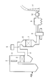
- FIG. 4 illustrates the configuration of a denitration apparatus using a selective catalytic reduction method.
- the combustion exhaust gas generated in the boiler 1 reaches the flue 4 via the super heater 2 and the economizer 3 and is led to the denitration reactor 6.
- An ammonia injector 5 is provided in the flue 4, and ammonia gas necessary for the denitration reaction is injected into the flue 4 from the ammonia injector 5.
- NOx in the combustion exhaust gas is decomposed into nitrogen and water while passing through the catalyst layer 7 disposed in the denitration reactor 6. Thereafter, the combustion exhaust gas passes through the air heater 8, the electric dust collector 9, and the combustion exhaust gas fan 10, and is discharged from the chimney 11 into the atmosphere.
- the catalyst layer 7 disposed in the denitration reactor 6 is mainly a gas parallel flow type catalyst having a lattice shape or a plate shape.
- a gas parallel flow type catalyst the combustion exhaust gas flows in parallel along the denitration catalyst surface. Therefore, there are few opportunities for the dust in the combustion exhaust gas to come into contact with the denitration catalyst surface, and there is an advantage that the deposition of the dust on the denitration catalyst surface is small. Therefore, it is widely used in denitration equipment for coal burning, denitration equipment for heavy oil burning, and the like.
- a denitration catalyst employed in such a denitration apparatus uses titanium oxide (TiO 2 ) as a base material.
- the base material carries active components such as vanadium pentoxide (V 2 O 5 ), tungsten oxide (WO 3 ), and molybdenum oxide (MoO 3 ).
- the above-mentioned denitration catalyst can obtain high denitration performance over a wide temperature range, but there is a problem that the denitration performance gradually deteriorates when used for a long time.
- the reasons for the reduction in NOx removal performance are (1) dust adhering to the surface of the NOx removal catalyst and blocking the gas passage hole, and (2) poisoning components in the dust adhering to the surface of the NOx removal catalyst diffuse into the NOx removal catalyst.
- the substance that becomes the catalyst poison contained in the fuel is gasified in the furnace and is physically adsorbed on the denitration catalyst, or chemically reacts with the catalyst components, For example, preventing the progress of the denitration reaction.
- the performance degradation caused by the deposition of dust on the surface of the denitration catalyst is caused by the amount of dust reaching the catalyst layer 7 by providing a dust removal device on the combustion exhaust gas inlet side of the catalyst layer 7. It can be expected to reduce the NOx reduction performance.
- the denitration catalyst is poisoned by the gaseous component, there is currently no measure for preventing the poisoning component from flying to the catalyst layer 7. Therefore, the durability of the denitration catalyst greatly depends on the type and amount of harmful substances contained in the fuel.
- coal In coal-fired boilers, coal is used as fuel. Coal quality varies greatly depending on the production area, and some coals contain a lot of arsenic. Arsenic is a poisoned component and has a strong effect as a catalyst poison. When coal containing arsenic in ppm order is used as a fuel, arsenic adheres to the active sites of the denitration catalyst and deactivates the active sites in tens of thousands of hours. Therefore, in coal-fired boilers, arsenic countermeasures are important in installing denitration equipment.
- Arsenic in the fuel is mostly gasified when the fuel burns in the furnace and exists in the form of arsenic trioxide (As 2 O 3 ).
- As 2 O 3 gas is expected to undergo a thermodynamic reaction of formula (I) or formula (II) in the temperature range near the denitration device.
- As 2 O 3 reacts with surrounding oxygen to change to solid state diarsenic pentoxide (As 2 O 5 ). In the formula (II), As 2 O 3 reacts with CaO contained in soot and changes to solid calcium arsenate (Ca 3 (AsO 4 ) 2 ).
- Patent Document 3 and Patent Document 4 propose a method of cleaning a denitration catalyst in a wet manner with an acid aqueous solution having a pH of 4 or less and quaternary ammonium hydroxide.
- Patent Document 5 proposes a method of separating arsenic from a denitration catalyst using an inert gas such as Ar, N 2 and He containing a reducing agent.
- the reducing agent is H 2 , CO or CH 4 and is contained in an inert gas at 2% (on a vol basis).
- treatment with an inert gas containing a reducing agent is performed at a temperature condition of 500 ° C. or higher, preferably 700 ° C. to 900 ° C.
- Patent Document 6 proposes a method in which HCl is added to SO 2 , CO, H 2 , CH 4 , NH 3, etc., and reduction treatment is performed, followed by washing treatment with a polyfunctional complex formation product.
- JP-A 63-65937 Japanese Patent Publication No. 07-029049 JP 2005-87901 A JP 2004-66101 A US Pat. No. 5,942,458 US Pat. No. 6,596,661
- Patent Document 1 and Patent Document 2 have not been put into practical use, and the denitration catalyst for coal-fired boilers that have been used for a long time has been replaced as a consumable because the denitration performance is reduced due to arsenic. ing.
- Patent Document 6 describes that a method using a reducing agent cannot be treated with As, and therefore needs to be washed with a polyfunctional complex-forming product. That is, similarly to Patent Document 3 and Patent Document 4, a wet cleaning step is essential.
- the denitration catalyst since there is no practical technique for separating arsenic from the denitration catalyst, the denitration catalyst whose performance has been degraded due to arsenic has been discarded.
- the denitration catalyst contains many rare metals such as titanium dioxide, tungsten, molybdenum, vanadium, etc., and a technique for recovering and recycling the rare metal is desired.
- the present invention has been made in view of such circumstances, and an object thereof is to provide a practical method for separating an arsenic compound in a dry manner from a denitration catalyst contaminated with used arsenic.
- the present invention heat-treats a denitration catalyst contaminated with an arsenic compound at a predetermined temperature while exposing it to a hydrocarbon compound or oxygen-containing carbon compound excluding CH 4 in a reducing atmosphere.
- a method for removing an arsenic compound is provided.
- the denitration catalyst contaminated with an arsenic compound is exposed to a hydrocarbon compound (excluding CH 4 ) or an oxygen-containing carbon compound and subjected to heat treatment, whereby the arsenic compound is separated and removed from the denitration catalyst.
- the hydrocarbon compound and the oxygen-containing carbon compound are preferably gases at the predetermined temperature.
- the denitration catalyst contaminated with an arsenic compound may be exposed to a gaseous hydrocarbon compound or oxygen-containing carbon compound.
- the arsenic compound can be separated and removed at a low temperature by a dry process that has not been possible in the past.
- the predetermined temperature is preferably higher than 300 ° C. and 600 ° C. or lower.
- the denitration catalyst contaminated with the arsenic compound is exposed to a hydrocarbon compound (except CH 4 ) or an oxygen-containing carbon compound, denitration is performed even when heat treatment is performed at a low temperature of 600 ° C. or lower. It becomes possible to separate and remove the arsenic compound from the catalyst. If the temperature of the heat treatment is too low, the arsenic compound cannot be separated and removed from the denitration catalyst.
- the denitration catalyst contaminated with the arsenic compound may be exposed to the hydrocarbon compound or the oxygen-containing carbon compound after being made into a product shape or a particle shape by pulverization treatment.
- the denitration catalyst contaminated with an arsenic compound may be in the shape of a product used in an actual machine or in the shape of particles produced by pulverizing a product.
- the arsenic compound can be separated and removed from the denitration catalyst by heating at a predetermined temperature and exposing to a hydrocarbon compound or an oxygen-containing carbon compound.
- the present invention provides a method for regenerating a denitration catalyst that removes an arsenic compound by the method for removing an arsenic compound.
- a denitration catalyst used for a long time is contaminated with an arsenic compound, and the catalyst performance decreases.
- the denitration catalyst can be recycled without being discarded as a consumable.
- since the arsenic compound can be separated and removed by a dry process it is not necessary to discard the cleaning liquid containing arsenic.
- the arsenic compound can be removed from the denitration catalyst while suppressing the deterioration of the denitration catalyst.
- the rare metal such as titanium dioxide, tungsten, molybdenum, vanadium and the like contained in the denitration catalyst can be reused without being discarded.
- the denitration catalyst from which the arsenic compound has been removed is preferably heat-treated at 250 ° C. or higher in an oxygen atmosphere.
- the arsenic compound can be separated and removed at a low temperature by a dry process that has not been possible in the past.
- the present invention provides a denitration catalyst regenerated by the above denitration catalyst regeneration method. Since the denitration catalyst regenerated as described above has improved catalyst performance, it can be reused as a denitration catalyst.
- an arsenic compound can be separated at a low temperature by a dry process from a denitration catalyst contaminated with a used arsenic compound by a practical method.
- the denitration catalyst contaminated with the arsenic compound is subjected to heat treatment at a predetermined temperature while being exposed to a hydrocarbon compound (excluding CH 4 ) or an oxygen-containing carbon compound in a reducing atmosphere.
- a hydrocarbon compound excluding CH 4
- an oxygen-containing carbon compound in a reducing atmosphere.
- the denitration catalyst from which the arsenic compound has been removed is preferably heat-treated at 250 ° C. or higher in an oxygen atmosphere.
- the carbon compound excessively attached to the denitration catalyst can be removed from the denitration catalyst.
- the denitration catalyst includes any component of titanium dioxide (TiO 2 ), tungsten oxide (WO 3 ), molybdenum oxide (MoO 3 ), and vanadium pentoxide (V 2 O 5 ), which are rare metals.
- TiO 2 titanium dioxide
- WO 3 tungsten oxide
- MoO 3 molybdenum oxide
- V 2 O 5 vanadium pentoxide
- contaminated with an arsenic compound refers to a state in which the arsenic compound is physically attached to the surface of the denitration catalyst, or a state in which arsenic or an arsenic compound is chemically bonded to the surface of the denitration catalyst.
- Hydrocarbon compounds (except CH 4 ) or oxygen-containing carbon compounds (alcohols) act as reducing agents. By setting the number of carbon atoms to 2 or more, it is possible to ensure the reactivity as the reducing agent.
- the hydrocarbon compound (excluding CH 4 ) or the oxygen-containing carbon compound preferably has a characteristic of being present in a gas when heat-treated at a predetermined temperature.
- the carbon number is preferably C 2 to C 18 and more preferably C 2 to C 4 .
- hydrocarbon compounds (except CH 4 ) are ethane (C 2 H 6 ), propane (C 3 H 8 ), cyclopropane (C 3 H 6 ), propene (C 3 H 6 ), butane.
- the denitration catalyst may be in product shape or particle shape.
- the product shape of the denitration catalyst is a honeycomb.
- the particle-shaped denitration catalyst can be prepared by pulverizing a denitration catalyst product by an appropriate method.
- the size of the particles is not particularly limited, but the reaction area can be increased by finely grinding the product.
- the predetermined temperature during the heat treatment is higher than 300 ° C. and 600 ° C. or lower, preferably 350 ° C. or higher and 600 ° C. or lower, more preferably 400 ° C. or higher and 500 ° C. or lower. If the predetermined temperature is too low, arsenic cannot be removed from the denitration catalyst. If the predetermined temperature is too higher than the firing temperature of the denitration catalyst, the denitration catalyst is deteriorated and the catalyst performance is lowered.
- the heat treatment time is appropriately set according to the shape of the denitration catalyst, the amount of the denitration catalyst, the heat treatment temperature, the heated gas composition, and the like.
- the denitration catalyst from which arsenic has been removed has improved denitration performance and can be used again as a denitration catalyst.
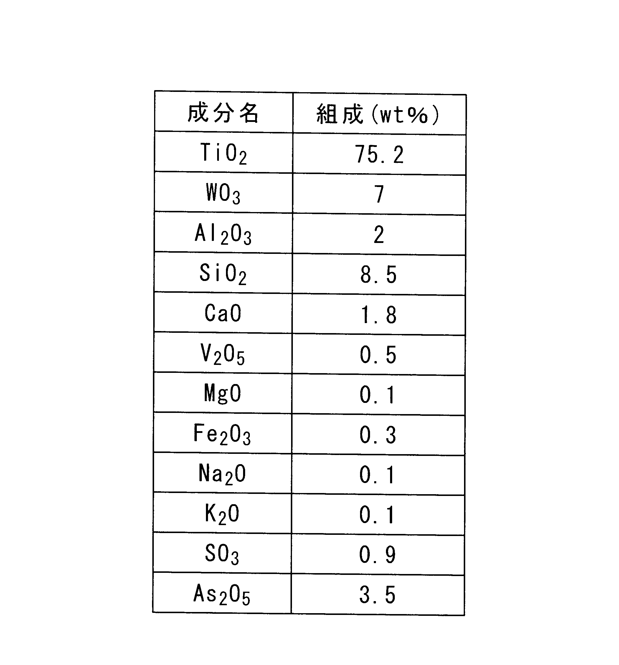
- Example 1 As the denitration catalyst A, a catalyst having the composition shown in Table 1 was used. The composition of the denitration catalyst A was analyzed by ICP (Induced Coupled Plasma Emission Spectroscopy). The denitration catalyst A is a denitration apparatus in an actual machine of a coal-fired boiler and is a catalyst actually used for 3500 hours. The denitration catalyst A contains diarsenic pentoxide at a rate of 3.5 wt%.
- the denitration catalyst A was pulverized with a mill to produce particles A of 200 mesh or less.
- 0.2 g of particle A was put in a reaction tube of a silica tube.
- a test of the following conditions was carried out in an electric furnace using the reaction tube, and the state of arsenic desorption from the catalyst was investigated.
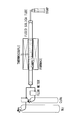
- FIG. 1 shows a schematic diagram of a test apparatus.
- the reaction tube is put in an electric furnace, and gaseous hydrocarbon compound (C 3 H 6 gas) is supplied into the electric furnace at the above processing gas flow rate while raising the electric furnace at a temperature rising rate of 10 ° C. per minute. did.
- the C 3 H 6 gas filled in the electric furnace is exhausted to the outside of the electric furnace via a trap having an absorbing solution capable of absorbing an arsenic component.
- a new sample powder was put into a reaction tube for each test, and five tests of room temperature to 100 ° C., room temperature to 200 ° C., room temperature to 300 ° C., room temperature to 400 ° C., and room temperature to 500 ° C. were performed.
- the volatilization amount was calculated from the difference from the concentration before processing by measuring the arsenic content of the powder after the test using an ICP (Emission Spectrometer).
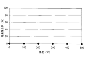
- FIG. 2 shows the arsenic ratio in the volatile component when treated with C 3 H 6 gas.
- the horizontal axis represents temperature and the vertical axis represents the arsenic removal rate.
- the arsenic removal rate was set to 100 when all the arsenic components contained in the particles A before treatment were removed.
- the arsenic component is vaporized and separated from the particles A by heat-treating the arsenic-containing catalyst in a C 3 H 6 gas atmosphere at a temperature ranging from over 300 ° C. to about 500 ° C. I understood that. That is, it was shown that the arsenic compound can be separated and removed from the denitration catalyst.
- Example 2 the same results as in Example 1 were obtained even when the denitration catalyst A was exposed to a hydrocarbon compound other than CH 4 in a reducing atmosphere in the honeycomb shape before pulverization.
- Example 1 The same denitration catalyst A as in Example 1 was used. In the same manner as in Example 1, the denitration catalyst A was pulverized to produce particles A of 200 mesh or less. An equal amount (on a weight basis) of granular solid carbon produced by carbonizing phenolphthalein as a reducing agent was mixed with 0.2 g of particles A, and the mixed particles were put into a reaction tube of a silica tube. A test of the following conditions was carried out in an electric furnace using the reaction tube, and the state of arsenic desorption from the catalyst was investigated.
- FIG. 3 shows the arsenic ratio in the volatile component when treated with N 2 gas.
- the horizontal axis represents temperature and the vertical axis represents the arsenic removal rate.
- the arsenic removal rate was set to 100 when all the arsenic components contained in the particles A before treatment were removed.
- FIG. 3 shows that the arsenic compound cannot be removed even when solid carbon is mixed with a catalyst containing the arsenic compound in a N 2 gas atmosphere and heat treatment ( ⁇ 500 ° C.).
Landscapes
- Chemical & Material Sciences (AREA)
- Organic Chemistry (AREA)
- Chemical Kinetics & Catalysis (AREA)
- Engineering & Computer Science (AREA)
- Materials Engineering (AREA)
- Exhaust Gas Treatment By Means Of Catalyst (AREA)
- Catalysts (AREA)
Abstract
Description
これに対して、上記(3)のように、ガス状成分によって脱硝触媒が被毒される場合は、触媒層7への被毒成分の飛来を防ぐ策がないのが現状である。そのため、脱硝触媒の耐久性は、燃料中に含まれる有害物質の種類や、その量によって大きく左右されることとなる。
As2O3+O2→As2O5・・・・・・(I)
3CaO+As2O3+O2→Ca3(AsO4)2・・・・・・(II)
(II)式では、As2O3が煤塵中に含まれるCaOと反応して固体状態の砒酸カルシウム(Ca3(AsO4)2)に変化する。
長時間使用した脱硝触媒は、砒素化合物で汚染され、触媒性能が低下する。上記発明によれば、上記方法により砒素化合物を除去することで、脱硝触媒を消耗品として廃棄せずに、再生利用することが可能となる。上記発明によれば、乾式プロセスにより砒素化合物を分離・除去することができるため、砒素を含有する洗浄液を廃棄処理する必要がない。上記発明によれば、低温で処理するため、脱硝触媒の劣化を抑制しつつ、脱硝触媒から砒素化合物を除去することができる。上記発明によれば、脱硝触媒に含まれている、二酸化チタン、タングステン、モリブデン、バナジウム等のレアーメタルを廃棄することなく再利用することができる。
上記のように再生された脱硝触媒は、触媒性能が改善されているため、脱硝触媒として再利用することができる。
本実施形態において、脱硝触媒は、砒素を含む石炭を燃料とする石炭焚きボイラで長時間使用されたものとする。砒素を含む石炭を燃料とする石炭焚きボイラにおいて、長時間使用した脱硝触媒は、煤塵中に含まれる砒素化合物で汚染される。砒素は、脱硝触媒にとって被毒成分である。脱硝触媒が砒素化合物で汚染されると、脱硝触媒の触媒性能が低下する。ここで「砒素化合物で汚染される」とは、砒素化合物が脱硝触媒の表面に物理的に付着した状態、あるいは、砒素または砒素化合物が脱硝触媒の表面に化学的に結合した状態を指す。
脱硝触媒Aとして、表1に示す組成の触媒を使用した。脱硝触媒Aの組成は、ICP(Induced Coupled Plasma Emission Spectroscopy)により分析した。脱硝触媒Aは、石炭焚きボイラの実機中の脱硝装置で、実際に3500時間使用された触媒である。脱硝触媒Aは、五酸化二砒素を3.5wt%の割合で含む。
温度;100℃~500℃
温度上昇率;10℃/min
処理ガス;C3H6(プロペン)
処理ガス流量;100NTP-mL/min(NTP:標準状態、normal temperature and pressure)
脱硝触媒Aは実施例1と同様のものを使用した。実施例1と同様に、脱硝触媒Aを粉砕し、200mesh以下の粒子Aを作製した。0.2gの粒子Aに、還元剤としてフェノールフタレインを炭化させて作製した粒状の固体炭素を等量(重量ベースで)混合し、この混合粒子をシリカチューブの反応管に入れた。該反応管を用いて電気炉で下記条件の試験を実施し、触媒からの砒素の脱離状況を調査した。
温度;100℃~500℃
温度上昇率;10℃/min
処理ガス;N2
処理ガス流量;100NTP-mL/min(NTP:normal temperature and pressure)
詳細には、粒子Aに固体炭素の粒子を混合させ、処理ガスをN2とした以外は、実施例1と同様に処理し、揮発成分中の砒素含有量を測定した。
2 スーパーヒータ
3 エコノマイザ
4 煙道
5 アンモニア注入器
6 脱硝反応器
7 触媒層
8 エアヒータ
9 電気集塵器
10 燃焼排ガスファン
11 煙突
Claims (7)
- 砒素化合物で汚染された脱硝触媒を、還元雰囲気下で、CH4を除く炭化水素化合物または含酸素炭素化合物に曝露させつつ、所定温度で加熱処理する砒素化合物の除去方法。
- 前記炭化水素化合物及び前記含酸素炭素化合物が、前記所定温度にて気体である請求項1に記載の砒素化合物の除去方法。
- 前記所定温度を、300℃より高く600℃以下とする請求項1または請求項2に記載の砒素化合物の除去方法。
- 前記砒素化合物で汚染された脱硝触媒を、製品形状のまま、または粉砕処理により粒子形状とした後、前記炭化水素化合物または前記含酸素炭素化合物に曝露させる請求項1乃至請求項3のいずれかに記載の砒素化合物の除去方法。
- 請求項1乃至請求項4に記載の砒素化合物の除去方法にて砒素化合物を除去する脱硝触媒の再生方法。
- 砒素を除去した前記脱硝触媒を、酸素雰囲気において250℃以上で加熱処理する請求項5に記載の脱硝触媒の再生方法。
- 請求項5または請求項6に記載の方法で再生された脱硝触媒。
Priority Applications (3)
| Application Number | Priority Date | Filing Date | Title |
|---|---|---|---|
| JP2013507282A JP5716188B2 (ja) | 2011-03-29 | 2012-02-24 | 砒素化合物の除去方法および除去装置、並びに脱硝触媒の再生方法および再生装置 |
| US14/007,940 US9114391B2 (en) | 2011-03-29 | 2012-02-24 | Method for removing arsenic compound, method for regenerating NOx removal catalyst, and NOx removal catalyst |
| US14/793,974 US9399213B2 (en) | 2011-03-29 | 2015-07-08 | Apparatus for removing arsenic compound |
Applications Claiming Priority (2)
| Application Number | Priority Date | Filing Date | Title |
|---|---|---|---|
| US201161468788P | 2011-03-29 | 2011-03-29 | |
| US61/468,788 | 2011-03-29 |
Related Child Applications (2)
| Application Number | Title | Priority Date | Filing Date |
|---|---|---|---|
| US14/007,940 A-371-Of-International US9114391B2 (en) | 2011-03-29 | 2012-02-24 | Method for removing arsenic compound, method for regenerating NOx removal catalyst, and NOx removal catalyst |
| US14/793,974 Division US9399213B2 (en) | 2011-03-29 | 2015-07-08 | Apparatus for removing arsenic compound |
Publications (1)
| Publication Number | Publication Date |
|---|---|
| WO2012132683A1 true WO2012132683A1 (ja) | 2012-10-04 |
Family
ID=46930443
Family Applications (1)
| Application Number | Title | Priority Date | Filing Date |
|---|---|---|---|
| PCT/JP2012/054538 Ceased WO2012132683A1 (ja) | 2011-03-29 | 2012-02-24 | 砒素化合物の除去方法、脱硝触媒の再生方法、並びに、脱硝触媒 |
Country Status (3)
| Country | Link |
|---|---|
| US (2) | US9114391B2 (ja) |
| JP (1) | JP5716188B2 (ja) |
| WO (1) | WO2012132683A1 (ja) |
Families Citing this family (2)
| Publication number | Priority date | Publication date | Assignee | Title |
|---|---|---|---|---|
| JP5748895B1 (ja) * | 2014-11-07 | 2015-07-15 | 三菱日立パワーシステムズ株式会社 | 排ガス処理システム及び処理方法 |
| JP5748894B1 (ja) * | 2014-11-07 | 2015-07-15 | 三菱重工業株式会社 | 排ガス処理方法及び脱硝・so3還元装置 |
Citations (6)
| Publication number | Priority date | Publication date | Assignee | Title |
|---|---|---|---|---|
| JPS6480444A (en) * | 1987-09-22 | 1989-03-27 | Mitsubishi Heavy Ind Ltd | Regeneration of denitration catalyst |
| JPH01139146A (ja) * | 1987-08-14 | 1989-05-31 | Mitsubishi Heavy Ind Ltd | 砒素分による劣化脱硝触媒の再生方法及び同装置 |
| JPH04161230A (ja) * | 1990-10-25 | 1992-06-04 | Osaka Gas Co Ltd | NOxの分解除去方法 |
| JP2000037635A (ja) * | 1998-07-24 | 2000-02-08 | Mitsubishi Heavy Ind Ltd | 脱硝触媒の再生方法 |
| JP2009226388A (ja) * | 2008-02-29 | 2009-10-08 | Mitsubishi Heavy Ind Ltd | 排ガス処理触媒の再生方法及びこの方法を使用した排ガス処理触媒 |
| JP4574851B2 (ja) * | 1998-07-16 | 2010-11-04 | アルギロン ゲゼルシャフト ミット ベシュレンクテル ハフツング | 不活性化した触媒の再生方法 |
Family Cites Families (9)
| Publication number | Priority date | Publication date | Assignee | Title |
|---|---|---|---|---|
| JPS6365937A (ja) | 1986-09-08 | 1988-03-24 | Mitsubishi Heavy Ind Ltd | 排煙脱硝方法 |
| JPH0729049B2 (ja) | 1987-04-30 | 1995-04-05 | 三菱重工業株式会社 | 燃焼排ガス中の砒素化合物除去方法 |
| FR2752175B1 (fr) | 1996-08-12 | 1998-09-11 | Pro Catalyse | Procede de traitement d'un catalyseur presentant une phase active a base de plomb et contamine par un compose de l'arsenic |
| US6395665B2 (en) | 1998-07-24 | 2002-05-28 | Mitsubishi Heavy Industries, Ltd. | Methods for the regeneration of a denitration catalyst |
| JP4149760B2 (ja) | 2002-08-06 | 2008-09-17 | バブコック日立株式会社 | 脱硝触媒の再生法 |
| JP4264643B2 (ja) | 2003-09-18 | 2009-05-20 | 日立造船株式会社 | 劣化触媒の再生方法 |
| JP5223085B2 (ja) | 2007-03-13 | 2013-06-26 | 国立大学法人秋田大学 | 塩化揮発法によるレアメタルの分離精製方法 |
| JP2009132960A (ja) | 2007-11-29 | 2009-06-18 | Akita Univ | 塩化揮発法による分離精製方法 |
| JP5504531B2 (ja) | 2009-09-29 | 2014-05-28 | 国立大学法人秋田大学 | 金属元素の分離方法及び分離装置 |
-
2012
- 2012-02-24 JP JP2013507282A patent/JP5716188B2/ja active Active
- 2012-02-24 US US14/007,940 patent/US9114391B2/en active Active
- 2012-02-24 WO PCT/JP2012/054538 patent/WO2012132683A1/ja not_active Ceased
-
2015
- 2015-07-08 US US14/793,974 patent/US9399213B2/en active Active
Patent Citations (6)
| Publication number | Priority date | Publication date | Assignee | Title |
|---|---|---|---|---|
| JPH01139146A (ja) * | 1987-08-14 | 1989-05-31 | Mitsubishi Heavy Ind Ltd | 砒素分による劣化脱硝触媒の再生方法及び同装置 |
| JPS6480444A (en) * | 1987-09-22 | 1989-03-27 | Mitsubishi Heavy Ind Ltd | Regeneration of denitration catalyst |
| JPH04161230A (ja) * | 1990-10-25 | 1992-06-04 | Osaka Gas Co Ltd | NOxの分解除去方法 |
| JP4574851B2 (ja) * | 1998-07-16 | 2010-11-04 | アルギロン ゲゼルシャフト ミット ベシュレンクテル ハフツング | 不活性化した触媒の再生方法 |
| JP2000037635A (ja) * | 1998-07-24 | 2000-02-08 | Mitsubishi Heavy Ind Ltd | 脱硝触媒の再生方法 |
| JP2009226388A (ja) * | 2008-02-29 | 2009-10-08 | Mitsubishi Heavy Ind Ltd | 排ガス処理触媒の再生方法及びこの方法を使用した排ガス処理触媒 |
Also Published As
| Publication number | Publication date |
|---|---|
| US20150306593A1 (en) | 2015-10-29 |
| JP5716188B2 (ja) | 2015-05-13 |
| JPWO2012132683A1 (ja) | 2014-07-24 |
| US20140018231A1 (en) | 2014-01-16 |
| US9114391B2 (en) | 2015-08-25 |
| US9399213B2 (en) | 2016-07-26 |
Similar Documents
| Publication | Publication Date | Title |
|---|---|---|
| JP3272367B2 (ja) | 脱硝用熱処理活性炭素繊維、その製造方法、それを用いた脱硝方法、及びそれを用いた脱硝システム | |
| Chen et al. | The enhancement of CuO modified V2O5-WO3/TiO2 based SCR catalyst for Hg° oxidation in simulated flue gas | |
| KR101345444B1 (ko) | 상용 탈질 scr 폐촉매의 현장 재제조 방법 | |
| JP2007530256A (ja) | 煙道ガスからの水銀除去を向上させるための臭素添加 | |
| KR101298305B1 (ko) | 배기가스 중 미량 유해물질의 제거장치 및 그 운전방법 | |
| JP5051977B2 (ja) | 排ガス中微量有害物質の除去装置及びその運転方法 | |
| Chiu et al. | Simultaneous control of elemental mercury/sulfur dioxide/nitrogen monoxide from coal-fired flue gases with metal oxide-impregnated activated carbon | |
| CN103619467B (zh) | 具有改善的抗中毒性能的催化剂 | |
| JP4936002B2 (ja) | 排ガス処理方法及び排ガス処理装置 | |
| Zhao et al. | Impact of individual flue gas components on mercury oxidation over a V 2 O 5–MoO 3/TiO 2 catalyst | |
| JP5716188B2 (ja) | 砒素化合物の除去方法および除去装置、並びに脱硝触媒の再生方法および再生装置 | |
| KR101154040B1 (ko) | 선택적촉매환원용 폐활성탄 촉매의 활성화 재생방법 | |
| CN112774687A (zh) | 一种协同脱除NO和VOCs的SCR催化剂及其制备方法 | |
| Chen et al. | Mechanism of Hg0 oxidation in the presence of HCl over a CuCl2-modified SCR catalyst | |
| KR20160075928A (ko) | NOx 및 SOx 동시 제거용 Fe-Cr/C 복합 촉매 및 이의 제조방법 | |
| KR100973675B1 (ko) | 배기가스 중 질소산화물 환원 및 원소수은 산화용 촉매 및 상기 촉매를 이용한 배기가스 중 질소산화물과 원소수은의 동시제거 방법 | |
| CN101024161B (zh) | 用于去除燃烧烟气中少量有害空气污染物的吸附剂及其制备方法 | |
| JP6400379B2 (ja) | 燃焼排ガスの脱硝方法 | |
| KR102472334B1 (ko) | 배가스 내 먼지 및 휘발성 유기화합물 동시처리 집진장치 | |
| JP2008030017A (ja) | 排ガス中微量有害物質の除去装置及びその運転方法 | |
| KR102201771B1 (ko) | 화력발전소 scr 반응기에서 금속수은 산화 촉진을 위한 염화암모늄 주입장치 및 이를 이용한 주입방법 | |
| JP2009226298A (ja) | 排ガス処理方法及び排ガス処理装置 | |
| JP5186699B2 (ja) | 排ガス中の金属水銀の酸化触媒及び該触媒を用いた金属水銀の酸化処理方法 | |
| JP2010022974A (ja) | 排ガス処理方法及び排ガス処理装置 | |
| Qin et al. | Experimental Research on Mercury Catalytic Oxidation over Ce Modified SCR Catalyst |
Legal Events
| Date | Code | Title | Description |
|---|---|---|---|
| 121 | Ep: the epo has been informed by wipo that ep was designated in this application |
Ref document number: 12765087 Country of ref document: EP Kind code of ref document: A1 |
|
| WWE | Wipo information: entry into national phase |
Ref document number: 14007940 Country of ref document: US |
|
| ENP | Entry into the national phase |
Ref document number: 2013507282 Country of ref document: JP Kind code of ref document: A |
|
| NENP | Non-entry into the national phase |
Ref country code: DE |
|
| 122 | Ep: pct application non-entry in european phase |
Ref document number: 12765087 Country of ref document: EP Kind code of ref document: A1 |