WO2012132272A1 - Machine à laver à tambour - Google Patents
Machine à laver à tambour Download PDFInfo
- Publication number
- WO2012132272A1 WO2012132272A1 PCT/JP2012/001716 JP2012001716W WO2012132272A1 WO 2012132272 A1 WO2012132272 A1 WO 2012132272A1 JP 2012001716 W JP2012001716 W JP 2012001716W WO 2012132272 A1 WO2012132272 A1 WO 2012132272A1
- Authority
- WO
- WIPO (PCT)
- Prior art keywords
- water
- drum
- rotary drum
- drainage
- laundry
- Prior art date
Links
Images


Classifications
-
- D—TEXTILES; PAPER
- D06—TREATMENT OF TEXTILES OR THE LIKE; LAUNDERING; FLEXIBLE MATERIALS NOT OTHERWISE PROVIDED FOR
- D06F—LAUNDERING, DRYING, IRONING, PRESSING OR FOLDING TEXTILE ARTICLES
- D06F33/00—Control of operations performed in washing machines or washer-dryers
- D06F33/30—Control of washing machines characterised by the purpose or target of the control
- D06F33/32—Control of operational steps, e.g. optimisation or improvement of operational steps depending on the condition of the laundry
-
- D—TEXTILES; PAPER
- D06—TREATMENT OF TEXTILES OR THE LIKE; LAUNDERING; FLEXIBLE MATERIALS NOT OTHERWISE PROVIDED FOR
- D06F—LAUNDERING, DRYING, IRONING, PRESSING OR FOLDING TEXTILE ARTICLES
- D06F2103/00—Parameters monitored or detected for the control of domestic laundry washing machines, washer-dryers or laundry dryers
- D06F2103/18—Washing liquid level
-
- D—TEXTILES; PAPER
- D06—TREATMENT OF TEXTILES OR THE LIKE; LAUNDERING; FLEXIBLE MATERIALS NOT OTHERWISE PROVIDED FOR
- D06F—LAUNDERING, DRYING, IRONING, PRESSING OR FOLDING TEXTILE ARTICLES
- D06F2103/00—Parameters monitored or detected for the control of domestic laundry washing machines, washer-dryers or laundry dryers
- D06F2103/24—Spin speed; Drum movements
-
- D—TEXTILES; PAPER
- D06—TREATMENT OF TEXTILES OR THE LIKE; LAUNDERING; FLEXIBLE MATERIALS NOT OTHERWISE PROVIDED FOR
- D06F—LAUNDERING, DRYING, IRONING, PRESSING OR FOLDING TEXTILE ARTICLES
- D06F2105/00—Systems or parameters controlled or affected by the control systems of washing machines, washer-dryers or laundry dryers
- D06F2105/06—Recirculation of washing liquids, e.g. by pumps or diverting valves
-
- D—TEXTILES; PAPER
- D06—TREATMENT OF TEXTILES OR THE LIKE; LAUNDERING; FLEXIBLE MATERIALS NOT OTHERWISE PROVIDED FOR
- D06F—LAUNDERING, DRYING, IRONING, PRESSING OR FOLDING TEXTILE ARTICLES
- D06F2105/00—Systems or parameters controlled or affected by the control systems of washing machines, washer-dryers or laundry dryers
- D06F2105/08—Draining of washing liquids
-
- D—TEXTILES; PAPER
- D06—TREATMENT OF TEXTILES OR THE LIKE; LAUNDERING; FLEXIBLE MATERIALS NOT OTHERWISE PROVIDED FOR
- D06F—LAUNDERING, DRYING, IRONING, PRESSING OR FOLDING TEXTILE ARTICLES
- D06F39/00—Details of washing machines not specific to a single type of machines covered by groups D06F9/00 - D06F27/00
- D06F39/08—Liquid supply or discharge arrangements
- D06F39/083—Liquid discharge or recirculation arrangements
Definitions
- the present invention relates to a drum-type washing machine for washing by sequentially controlling each step such as washing, rinsing and dewatering.
- the stopped rotating drum is rotated at low speed, and the dewatering step is started early.
- the conventional drum-type washing machine stops the rotary drum from the start of drainage until the driving condition is reached. That is, after the drive condition is reached, the rotation of the rotary drum is started. Therefore, although the washing time can be shortened, there is a problem that the rinsing performance becomes insufficient because the water level in the water tank is lowered and the rinsing starts.
- the drum-type washing machine comprises a rotary drum for containing laundry, a water tank for rotatably supporting the rotary drum, a motor for rotatably driving the rotary drum, a water supply valve for supplying water into the water tank, and
- the control unit has a drainage unit for draining and a control unit having a control unit for controlling at least washing, rinsing, and dewatering steps, and the control unit rotates the rotating drum in a certain direction in the rinsing step before draining by the drainage unit.
- the rotation speed of the rotary drum is controlled so that the laundry adheres to the inner peripheral wall of the rotary drum at least during drainage.
- FIG. 1 is a cross-sectional view of a drum-type washing machine according to a first embodiment of the present invention.
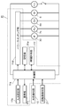
- FIG. 2 is a block diagram for explaining a control circuit of the drum type washing machine.
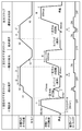
- FIG. 3 is a time chart showing the operation of the rinsing step and the dewatering step of the drum type washing machine.
- FIG. 4 is a time chart showing the operation of the rinsing step and the dewatering step of the drum-type washing machine in Embodiment 2 of the present invention.
- Embodiment 1 the drum type washing machine of Embodiment 1 of this invention is demonstrated using FIG.
- FIG. 1 is a cross-sectional view of a drum-type washing machine according to a first embodiment of the present invention.
- the drum-type washing machine includes at least a rotating drum 4, a water tank 3, a motor 6, a water supply valve 7 b, a drainage valve 8 b which is a drainage portion, and a control device 11. And.
- the water tank 3 is swingably provided inside the main body 1, and a rotating drum 4 is rotatably provided inside the water tank 3. Then, the rotary drum 4 is rotationally driven in the forward and reverse directions about the rotation shaft 4 a by the motor 6 attached to the outside on the back side of the water tank 3.
- the inner circumferential wall 4 c of the rotary drum 4 is provided with, for example, a plurality of stirring protrusions 4 b for stirring laundry such as clothes, and a plurality of through holes 4 e communicating with the water tank 3.
- the rear wall 4 d which is the bottom of the rotary drum 4 is formed with a plurality of rear openings 4 g along the circumferential direction.
- the back opening 4 g is provided to face the air guide opening 18 formed on the back side of the water tank 3.
- the rotary shaft 4a of the rotary drum 4 is inclined downward, for example, at an angle ⁇ of 20 ⁇ 15 degrees, from the horizontal direction X from the front side to the rear side.
- the opening 13 of the water tank 3 can be provided upward by inclining the rotation shaft 4a.
- the user can take laundry in and out of the rotary drum 4 through the opening 13 of the water tank 3 without taking a posture of bending greatly.
- the water tank 3 is provided inside the main body 1 at the same inclination as the rotating drum 4.
- a deep water storage state can be obtained even with a small amount of water accumulated in the water tank 3 on the back side.
- the rinse effect can be further enhanced. Therefore, even if the water level in the rotary drum 4 drops during drainage, the laundry can be made to penetrate water for a long time as compared with the case where the rotary shaft 4a is horizontal, and the rinse performance can be improved.
- the rotational axis 4a may be horizontal or the inclination angle ⁇ may be less than 5 degrees. This improves the degree of freedom in the design of the drum-type washing machine.
- a door 5 which can be opened and closed is provided opposite to the opening 13 of the water tank 3, and the user can load laundry such as clothes into the rotating drum 4 via the door 5. .
- an annular seal member 14 having elasticity is attached. Then, even if the water tank 3 swings up and down, right and left, and back and forth, the sealing material 14 is deformed and pressed to the back side of the door 5, so the tightness between the water tank 3 and the door 5 is maintained.
- the drainage unit 8 for draining water from the water tank 3 is provided below the water tank 3 below the water tank 3 .
- the drainage unit 8 is composed of a drainage pipe 8a whose one end is connected to the bottom of the water tank 3 and a drainage valve 8b.
- the drainage valve 8b drains the water in the water tank 3 in the open state through the drainage pipe 8a and stops the drainage in the closed state, as necessary after the end of the washing step or at the end of the rinsing step.
- a drying unit 9 is provided below the back side of the water tank 3.
- the drying unit 9 includes a blower 9c, an air blowing path 9d, an inlet 9e, an outlet 9f, a dehumidifying unit 9g, and a heating unit 9h.
- the blower 9 c sucks in air from an outlet 9 f for discharging the air from the water tank 3 and the rotary drum 4.
- the inlet 9 e is provided on the back side of the water tank 3, and blows the air sucked by the blower 9 c into the rotating drum 4.
- the high humidity air from the outlet 9f is dehumidified by the dehumidifying part 9g.
- the dehumidified air is heated by the heating unit 9 h provided downstream of the dehumidifying unit 9 g to become high temperature air.
- the dehumidifying part 9g and the heating part 9h are provided in the air flow path 9d which connects the air blower 9c and the inlet 9e.
- the dehumidifying unit 9g and the heating unit 9h may be configured by a heat pump unit, or the heating unit 9h may be configured by a heater, and the dehumidifying unit 9g may be configured by a water cooling system or an air cooling system. .
- the circulating water jet pipe 32 of the circulating water channel 31 is connected from the door 5 side to the injection port 51 provided on the front end wall 3 f at the end peripheral edge of the opening 13 of the water tank 3. Then, as indicated by arrow A in FIG. 1, the rotary drum 4 is formed through the flow path formed between the back surface of the front end wall 3f of the water tank 3 and the front surface of the front end wall 4f corresponding to the back surface of the front end wall 3f. Spout water inside.
- the water in the water tank 3 is circulated as needed at each step such as washing preparation, washing, rinsing, etc. for detecting the amount of clothes, etc. to prevent early dissolution of detergent and bias of laundry, and washing And improve the rinse performance.
- a DC brushless motor capable of controlling the number of rotations is used to adjust the flow rate and flow rate of the injected water.
- the motor 6 is driven to rotate.
- the number of rotations of the rotary drum 4 is increased to such an extent that the laundry sticks to the inner peripheral wall 4c of the rotary drum 4, for example, about 100 to 140 rpm.
- the energization of the motor 6 is turned off.
- the rotating drum 4 continues to rotate due to the inertia of the rotating drum 4.
- the rotary drum 4 is in the state of rotating the motor 6. After that, the rotation drum 4 stops its rotation due to resistance such as friction.
- the time from the stop of energization to the stop of the rotary drum 4 is long when the amount of laundry is large and short when the amount of laundry is small. Therefore, the amount of laundry is detected using the fact that the difference in the time required to stop the rotary drum 4 is proportional to the amount of laundry.
- a water level detection unit 10 for detecting the amount of water supplied to the inside of the rotary drum 4 is provided.
- the water level detection unit 10 is configured by connecting an air trap unit 10a provided at a predetermined position near the lower portion 3b of the rotary drum 4 and a pressure detection unit (not shown) by a hose 10b.
- the pressure detection unit includes, for example, a ferrite integrated in a bellows portion moved by pressure, and a stationary coil surrounding the periphery of the ferrite. Then, the movement stroke distance is converted to the pressure in the air trap portion 10a by utilizing the inductance change between the ferrite and the coil.
- the water level detection unit 10 is open to the atmosphere, and the output of the pressure detection unit is constant.
- the water level detection unit 10 generally senses by measuring the internal pressure of the air trap unit 10 a by the air trap mechanism, and measures the time until the internal pressure of the air trap unit 10 a changes from the stable open air pressure.
- the water level in the water tank 3 can be properly calculated without being affected by the variation of the water level sensor.
- the control device 11 to be described later has a table of a plurality of frequencies and water levels corresponding to the number of revolutions of the rotary drum 4. That is, the water level can be detected even when the rotating drum 4 is stationary or rotating.
- a rotation number detection unit 21 that detects the rotation number of the rotary drum 4 and a control device 11 are provided.
- control device 11 includes at least a control unit 11 a including, for example, a microprocessor, an input setting unit 11 b, a display unit 11 c, a storage unit 11 e, and a time measurement unit 11 f. Be done.
- a control unit 11 a including, for example, a microprocessor, an input setting unit 11 b, a display unit 11 c, a storage unit 11 e, and a time measurement unit 11 f. Be done.
- the control unit 11a of the control device 11 displays the information on the display unit 11c. Then, according to the input mode setting and control program stored in the storage unit 11e, the control unit 11a of the control device 11 controls the motor 6, the drain valve 8b, the circulation pump 30, the water supply valve 7b and the like via the power switching unit 11d. Automatic control. Thereby, the control device 11 controls a series of steps such as washing, rinsing and dewatering.
- the control unit 11a drives the water supply and drainage and the rotary drum 4 based on the signals from the time measurement unit 11f that measures time, the water level detection unit 10, and the rotation speed detection unit 21.
- the control unit 11a drives the water supply and drainage and the rotary drum 4 based on the signals from the time measurement unit 11f that measures time, the water level detection unit 10, and the rotation speed detection unit 21.
- the operation of dewatering while draining will be described as drainage dewatering.
- the drainage dewatering during the rinsing step is an operation of intermediate drainage dewatering
- the drainage dewatering during the dehydration step is the final drainage dewatering It explains as an operation.
- the door 5 is opened, and laundry such as clothes is thrown into the rotating drum 4 from the opening 13 of the water tank 3.
- the start switch (not shown) is operated to start the operation, the laundry amount is detected by the rotation of the rotary drum 4 and the laundry amount is detected.
- the water supply valve 7b is opened, and water of a water amount set in advance is supplied to the water tank 3 according to the detected laundry amount.
- the detergent contained in the detergent containing portion 7 a is introduced into the water tank 3 using the water supply.
- the control unit 11a When the water level in the water tank 3 exceeds a predetermined level, the control unit 11a operates the circulation pump 30 to accelerate the dissolution of the detergent. Further, the control unit 11 a controls the motor 6 to rotationally drive the rotary drum 4. As a result, the laundry in the rotary drum 4 is lifted in the rotational direction by the stirring projections 4 b and falls onto the surface of the water in which the detergent is dissolved from above the rotary drum 4 by its own weight. Is repeated. As a result, the penetration of the detergent into the laundry and the discharge of the detergent from the laundry cause the soil to be removed. Next, after a predetermined time has elapsed, the control unit 11a opens the drain valve 8b via the power switching unit 11d, drains the contaminated water in the water tank 3 from the drain pipe 8a, and ends the washing step Do.
- FIG. 3 is a time chart showing operations of the rinsing step and the dewatering step of the drum-type washing machine in the first embodiment of the present invention.
- each operation of intermediate dewatering mainly for dewatering and water supply stirring mainly for rinsing is sequentially performed.
- the control unit 11a is a balance for reducing the vibration generated when the rotary drum 4 is rotated at high speed by the laundry in the rotary drum 4.
- Start control The balance control usually rotates the rotary drum 4 at a rotational speed of, for example, 50 rpm, and detects the vibration of the rotary drum 4 with a general vibration detection sensor (not shown) such as an acceleration sensor, for example. To be executed.
- the control unit 11a After completion of the balance control, the control unit 11a increases the number of revolutions of the rotary drum 4 to a predetermined number of revolutions, for example, about 900 rpm, and removes water from the laundry by centrifugal force. After reaching a predetermined number of rotations, the number of rotations of the rotary drum 4 is maintained for a predetermined time t1. Thereafter, the drive of the motor 6 is stopped. Then, when the rotation of the rotary drum 4 is stopped, the operation of intermediate dewatering is ended, and the process shifts to the next water supply stirring. At this time, the laundry is stuck to the inner peripheral wall 4 c of the rotary drum 4.
- a predetermined number of revolutions for example, about 900 rpm
- the control unit 11a opens the water supply valve 7b and stores water in the water tank 3 while rotating the rotary drum 4 in a predetermined direction.
- the rotational speed of the rotary drum 4 is, for example, about 80 rpm such that the laundry sticks to the inner peripheral wall 4 c of the rotary drum 4.
- the control unit 11a controls the water supply valve 7b to stop the water supply and simultaneously turns on the circulation pump 30. Thereby, water is spouted from the spout 51 to the laundry in the rotating drum 4. At this time, the rotational speed of the rotary drum 4 is increased from 80 rpm to, for example, about 170 rpm, and lint of the laundry is removed by the drainage filter 8c.
- control unit 11 a reduces the number of rotations of the motor 6.
- the control unit 11a performs the tumbling operation of agitating the laundry in the rotary drum 4, and at the same time, starts the water supply into the water tank 3 and stops the operation of the circulation pump 30.
- the rotational direction of the rotary drum 4 may be forward or reverse, or may be rotation in a fixed direction.
- the laundry is pulled off from the inner peripheral wall 4c of the rotary drum 4, stirred in the water accumulated in the water tank 3, and rinsing is performed.
- the control unit 11 a rotates the rotating drum 4 in a fixed direction.
- the rotation direction may be the same as or opposite to the rotation direction at the time of the operation of water supply agitation in the first rinse step.
- a time t3 which is a first predetermined time is a time until the rotating drum 4 reaches a fixed rotation number in a fixed direction.
- the first number of rotations of the rotary drum 4 in the middle drainage dewatering of the second rinse step is lower than the second number of rotations in the middle dehydration of the first rinse step. That is, by lowering the number of revolutions of the rotary drum 4, it is possible to prevent all the water of the laundry from being removed. As a result, the rinse performance can be maintained without reducing the centrifugal force by the weight of the laundry containing water.
- control unit 11 a starts driving of the circulation pump 30 before starting drainage of the water in the water tank 3 while the rotary drum 4 is rotating.
- the predetermined water level h3 is a level at which the circulation pump 30 does not see air.
- the air in the circulation pump 30 can be prevented from leaking, and the water in the water tank 3 can be efficiently circulated through the circulation water jet pipe 32.
- the control unit 11a stops the rotation of the rotary drum 4. Then, when the rotation of the rotary drum 4 is stopped, the operation of intermediate drainage dewatering is finished, and the operation shifts to the operation of water supply and agitation of the next second rinse step.
- control unit 11a controls the water supply valve 7b to stop the water supply and simultaneously start the driving of the circulation pump 30.
- the control unit 11a stops the operation of the rotary drum 4 and the circulation pump 30, and the operation of the water supply stirring is ended.
- the second rinse step is completed, and the process proceeds to the final drainage dewatering of the next dewatering step.
- control unit 11a rotates the rotating drum 4 in a fixed direction.
- the direction of rotation may be the same as or opposite to the direction of rotation of the water supply and agitation operation in the first and second rinse steps.
- the laundry adheres to the inner circumferential wall 4c of the rotary drum 4, and the rotary drum 4 is rotated in a fixed direction at a predetermined rotational speed such as 80 rpm.
- the rotational speed of the rotary drum 4 may be, for example, 50 to 120 rpm, as long as the laundry adheres to the inner peripheral wall 4c of the rotary drum 4, and preferably, for example, a rotational speed in the range of 80 to 100 rpm.
- the number of rotations of the rotary drum 4 may not be constant, and may be increased stepwise or proportionally to a predetermined number of rotations.
- the control unit 11a controls the drain valve 8b to start draining water in the water tank 3. Thereby, the water level in the water tank 3 falls gradually.
- the control unit 11a increases the rotational speed of the rotary drum 4 to a high speed rotational speed of, for example, about 900 rpm. At this time, the laundry in the rotary drum 4 rotates in a state of being stuck to the inner peripheral wall 4 c of the rotary drum 4.
- control unit 11a starts driving of the circulation pump 30 before starting to drain water in the water tank 3 while the rotary drum 4 is rotating in a predetermined direction.
- the control unit 11a starts driving of the circulation pump 30. Then, the water which has passed through the circulation channel 31 from the water tank 3 by the circulation pump 30 is spouted from the injection port 51 to the laundry in the rotary drum 4. At this time, the laundry absorbs water by the spouted water. Furthermore, dehydration is also performed by the centrifugal force caused by the rotation of the rotary drum 4, and the laundry repeats water absorption and dehydration. This promotes the replacement of water with the laundry to dissolve the detergent components in the laundry into the water present around the laundry. In addition, detergent components remaining in the laundry can be efficiently removed. As a result, the detergent component in the laundry decreases in a short time.
- the control unit 11a stops the driving of the circulation pump 30.
- the water from the circulating water channel 31 can be ejected to the laundry in the rotary drum 4 until the water level of the water drops from the predetermined water level h4 to the predetermined water level h5. Therefore, the amount of water absorption of the laundry can be increased without increasing the amount of water supplied, and the amount of detergent components remaining in the laundry can be reduced.
- the predetermined water level h5 is a level at which the circulation pump 30 does not see air. Thus, the air in the circulation pump 30 can be prevented from leaking, and the water in the water tank 3 can be efficiently circulated through the circulation water jet pipe 32.
- the control unit 11a stops the operation of the rotary drum 4. Then, when the rotation of the rotary drum 4 is stopped, the operation of intermediate drainage dewatering is finished, and the dewatering step is finished.
- the time to start the water drainage can be set based on the time when the rotating drum 4 starts to rotate in a certain direction, the time to start the drainage can be set. It can be fixed. As a result, the time for starting drainage can be appropriately controlled to shorten the time and obtain a stable cleaning effect.
- the present embodiment it is possible to set the injection start time of the water jetted out through the circulation water passage 31 based on the time when the rotary drum 4 starts to rotate in a fixed direction. Thereby, the time to start the water circulation can be properly controlled to obtain a high cleaning effect.
- FIG. 4 is a time chart showing the operation of the rinsing step and the dewatering step of the drum-type washing machine in Embodiment 2 of the present invention.
- final drainage dewatering in the intermediate drainage dewatering and dewatering steps in the second rinsing step is different from that in the first embodiment.
- the other configurations and operations are the same as those of the first embodiment, and the same symbols are attached to the same configurations, and the detailed description uses the first embodiment.
- the control unit 11 a rotates the rotating drum 4 in a fixed direction.
- the rotation direction may be the same as or opposite to the rotation direction at the time of the operation of water supply agitation in the first rinse step.
- the rotation speed of the rotary drum 4 is a first rotation speed at which the laundry adheres to the inner circumferential wall 4c of the rotary drum 4 in a drained state, and is rotated in a fixed direction at a predetermined rotation speed such as 80 rpm.
- the rotational speed of the rotary drum 4 may be, for example, 50 to 120 rpm, as long as the laundry adheres to the inner peripheral wall 4c of the rotary drum 4, and more preferably, for example, the rotational speed in the range of 80 to 100 rpm.
- the number of rotations of the rotary drum 4 may not be constant, and may be increased stepwise or proportionally to a predetermined number of rotations.
- the control unit 11a drives the circulation pump 30. To start. Thereby, water can be stably spouted to the laundry through the circulation channel 31 in the rotary drum 4 in a state where the rotational speed of the rotary drum 4 is constant. As a result, the rinse performance of the laundry is improved.
- the control section 11a controls the drainage valve 8b to set the water in the water tank 3 Start drainage of water. Thereby, the water level in the water tank 3 falls gradually.
- the control unit 11a increases the rotation number of the rotary drum 4 to a high-speed rotation number, which is a second rotation number of about 500 rpm, for example. At this time, the laundry in the rotary drum 4 rotates in a state of being stuck to the inner peripheral wall 4 c of the rotary drum 4.
- the first number of rotations of the rotary drum 4 in the middle drainage dewatering of the second rinse step is lower than the second number of rotations in the middle dehydration of the first rinse step described in the first embodiment. I assume. That is, by lowering the number of revolutions of the rotary drum 4, it is possible to prevent all the water of the laundry from being removed. As a result, the weight of the water-containing laundry can maintain the rinse performance without reducing the centrifugal force.
- the control unit 11a stops driving of the circulation pump 30. Thereby, after the rotary drum 4 reaches the first rotation number, it is possible to shift to the next operation. As a result, the rinse performance of the laundry by centrifugal force is not reduced.
- the control unit 11a stops the operation of the rotary drum 4. Then, when the rotation of the rotary drum 4 is stopped, the intermediate drainage dewatering step is finished, and the operation of the next water supply stirring is performed.
- the control unit 11a opens the water supply valve 7b, stores water in the water tank 3, and at the same time starts a tumbling operation for agitating the rotary drum 4.
- the control unit 11a controls the water supply valve 7b to stop water supply.
- the control unit 11a starts the driving of the circulation pump 30. At this time, the water is accumulated in the water tank 3 to the water level h14, and the tumbling operation is performed. Thereby, the detergent component is dissolved out of the laundry in the water tank 3, and the rinse performance is improved.
- control part 11a stops operation of rotation drum 4 and circulation pump 30, and water supply stirring is completed.
- the second rinse step is completed, and the process proceeds to the final drainage dewatering of the next dewatering step.
- the control unit 11a rotates the rotating drum 4 in a fixed direction at a predetermined rotation speed at which the laundry adheres to the inner peripheral wall 4c of the rotating drum 4 while draining, for example, 80 rpm. Rotate in a fixed direction.
- the direction of rotation may be the same as or opposite to the direction of rotation at the time of feedwater agitation in the first and second rinse steps.
- the control unit 11a starts driving of the circulation pump 30.
- the control unit 11a controls the drainage valve 8b to start drainage of water in the water tank 3 . Thereby, the water level in the water tank 3 falls gradually.
- the control unit 11a increases the rotational speed of the rotary drum 4 to, for example, about 900 rpm. At this time, the laundry of the rotary drum 4 rotates in a state of being stuck to the inner peripheral wall 4 c of the rotary drum 4.
- control unit 11a stops the circulation pump 30.
- the control unit 11a stops the operation of the rotary drum 4. Then, when the rotation of the rotary drum 4 is stopped, the final drainage and dewatering operation is completed, and the dewatering step is completed.
- the rotary drum 4 is rotated in a certain direction before the start of drainage. After the rotational speed of the rotary drum 4 reaches a constant rotational speed, driving of the circulation pump 30 is started. Thereby, the water in the water tank 3 can be circulated in a state in which the rotation of the rotary drum 4 is stable, and the rinse performance is further improved.
- the through hole 4 e is preferably provided over the entire inner peripheral wall 4 c of the rotary drum 4, but the invention is not limited to this.
- the inner circumferential wall 4c of the rotary drum 4 may be partially formed, and the arrangement is not particularly limited as long as the water tank 3 and the rotary drum 4 communicate with each other.
- the water supply unit 7 has been described as an example provided above the water tank 3.
- the present invention is not limited to this. You may provide in the side and the bottom side.
- the drainage portion may also include, for example, a drainage pump, and the drainage pump may be used to drain the water in the water tank 3.
- the injection ports 51 may be provided not only in the lower part but also in the upper part, as long as the injection port 51 does not come in contact with the laundry in the rotary drum 4.
- the rotational speed of the rotary drum 4 is not particularly limited, and the setting can be arbitrarily changed in accordance with the amount of laundry and the degree of dirt.
- the on / off control of the circulation pump 30 is always set to on during the rinse step after turning on the circulation pump 30, but the on period is not particularly defined. On / off control may be performed as needed.
- the drum type washing machine was demonstrated to the example, it is not restricted to this.
- a vertical washing machine such as a pulsator agitation type or an agitator type.
- the laundry in order to allow the water to penetrate uniformly, the laundry may be uniformly wet from the outer peripheral side of the laundry using a shower or the like provided on the outer side of the rotating drum.
- the laundry when rotating the rotating drum during drainage, by making the pulsator and the rotating drum move integrally, the laundry may be attached to the rotating drum to absorb and dewater the laundry.
- the rotary drum 4 is rotated in a certain direction before starting drainage.
- the control unit 11a drives the drainage valve 8b to perform drainage, and at least during drainage, controls the number of rotations of the rotary drum 4 so that the laundry adheres to the inner peripheral wall 4c of the rotary drum 4 Do.
- the detergent component contained in the laundry is removed from the laundry by the centrifugal force due to the increase in the rotation speed of the rotating drum 4.
- the spouted water is replenished with water again to replenish the dewatered water.
- the detergent components in the laundry can be efficiently removed to improve the rinsing performance of the laundry.
- the rotary drum 4 can be rotated while maintaining a stable centrifugal force.
- the detergent component in the laundry dissolves out by repeating the absorption of water from the rinse water of the laundry at the time of drainage and the dehydration by the rotation of the rotating drum to improve the rinsing performance. It can be done. Therefore, it is applicable not only to a home-use washing machine but also to a washing machine for fibers and the like, and a business-use washing machine mainly made of washing with water.
Abstract
L'invention porte sur une machine à laver à tambour qui comprend : un tambour rotatif (4), une cuve à eau (3), un moteur (6), un robinet d'amenée d'eau (7b) servant à amener de l'eau à la cuve à eau, une partie de vidange servant à vider l'eau de l'intérieur de la cuve à eau, et une unité de commande (1) qui comprend une unité de commande (11a) servant à commander au moins le lavage, le rinçage et l'évacuation de l'eau. L'unité de commande (11a) assure la commande de telle sorte que, pendant l'étape de rinçage, le tambour rotatif (4) est mis en rotation dans un sens fixe, après quoi l'eau est évacuée au moyen de la partie de vidange et, au moins pendant que l'eau est vidangée, la vitesse de rotation du tambour rotatif (4) est une vitesse de rotation à laquelle les articles à laver adhèrent à la surface de paroi intérieure du tambour rotatif (4).
Priority Applications (2)
| Application Number | Priority Date | Filing Date | Title |
|---|---|---|---|
| CN2012800159623A CN103459701A (zh) | 2011-03-29 | 2012-03-13 | 滚筒式洗衣机 |
| EP12765324.4A EP2692930A4 (fr) | 2011-03-29 | 2012-03-13 | Machine à laver à tambour |
Applications Claiming Priority (2)
| Application Number | Priority Date | Filing Date | Title |
|---|---|---|---|
| JP2011071618A JP2012205625A (ja) | 2011-03-29 | 2011-03-29 | ドラム式洗濯機 |
| JP2011-071618 | 2011-03-29 |
Publications (1)
| Publication Number | Publication Date |
|---|---|
| WO2012132272A1 true WO2012132272A1 (fr) | 2012-10-04 |
Family
ID=46930065
Family Applications (1)
| Application Number | Title | Priority Date | Filing Date |
|---|---|---|---|
| PCT/JP2012/001716 WO2012132272A1 (fr) | 2011-03-29 | 2012-03-13 | Machine à laver à tambour |
Country Status (4)
| Country | Link |
|---|---|
| EP (1) | EP2692930A4 (fr) |
| JP (1) | JP2012205625A (fr) |
| CN (1) | CN103459701A (fr) |
| WO (1) | WO2012132272A1 (fr) |
Cited By (3)
| Publication number | Priority date | Publication date | Assignee | Title |
|---|---|---|---|---|
| WO2014161579A1 (fr) * | 2013-04-04 | 2014-10-09 | Arcelik Anonim Sirketi | Cycle de lavage à efficacité améliorée pour machine à laver |
| CN105518200A (zh) * | 2013-09-05 | 2016-04-20 | 三星电子株式会社 | 洗衣机以及控制该洗衣机的方法 |
| CN110387716A (zh) * | 2018-04-17 | 2019-10-29 | 松下知识产权经营株式会社 | 家用电器装置的排水方法 |
Families Citing this family (8)
| Publication number | Priority date | Publication date | Assignee | Title |
|---|---|---|---|---|
| JP2016123538A (ja) * | 2014-12-26 | 2016-07-11 | アクア株式会社 | 洗濯機 |
| KR102522794B1 (ko) * | 2016-02-01 | 2023-04-19 | 엘지전자 주식회사 | 드럼 세탁기 및 드럼 세탁기의 터브 세척 방법 |
| US11326292B2 (en) | 2016-02-01 | 2022-05-10 | Lg Electronics Inc. | Drum washing machine and method for cleaning tub thereof |
| DE102017201008B3 (de) * | 2017-01-23 | 2018-06-21 | BSH Hausgeräte GmbH | Wäschepflegegerät mit einer Steuerung |
| KR102539459B1 (ko) * | 2018-07-06 | 2023-06-01 | 엘지전자 주식회사 | 세탁물 처리기기 및 그 제어방법 |
| KR20210001726A (ko) * | 2019-06-28 | 2021-01-06 | 엘지전자 주식회사 | 세탁기의 제어방법 |
| JP7478920B2 (ja) * | 2019-12-11 | 2024-05-08 | パナソニックIpマネジメント株式会社 | 洗濯機、および洗濯機の制御方法 |
| DE102021205430A1 (de) * | 2021-05-28 | 2022-12-01 | BSH Hausgeräte GmbH | Wäschepflegegerät mit einer Steuerung |
Citations (3)
| Publication number | Priority date | Publication date | Assignee | Title |
|---|---|---|---|---|
| JP2001224886A (ja) * | 2000-02-15 | 2001-08-21 | Toshiba Corp | ドラム式洗濯機 |
| JP2004016399A (ja) * | 2002-06-14 | 2004-01-22 | Sharp Corp | 洗濯機 |
| JP2009078068A (ja) * | 2007-09-27 | 2009-04-16 | Sanyo Electric Co Ltd | 洗濯乾燥機 |
Family Cites Families (3)
| Publication number | Priority date | Publication date | Assignee | Title |
|---|---|---|---|---|
| KR100215416B1 (ko) * | 1995-04-29 | 1999-08-16 | 전주범 | 세탁기의헹굼방법 |
| GB0003008D0 (en) * | 2000-02-11 | 2000-03-29 | Notetry Ltd | A method of operating a domestic appliance |
| KR101487534B1 (ko) * | 2008-09-12 | 2015-01-28 | 엘지전자 주식회사 | 세탁물 처리기기 |
-
2011
- 2011-03-29 JP JP2011071618A patent/JP2012205625A/ja not_active Withdrawn
-
2012
- 2012-03-13 CN CN2012800159623A patent/CN103459701A/zh active Pending
- 2012-03-13 WO PCT/JP2012/001716 patent/WO2012132272A1/fr unknown
- 2012-03-13 EP EP12765324.4A patent/EP2692930A4/fr not_active Withdrawn
Patent Citations (3)
| Publication number | Priority date | Publication date | Assignee | Title |
|---|---|---|---|---|
| JP2001224886A (ja) * | 2000-02-15 | 2001-08-21 | Toshiba Corp | ドラム式洗濯機 |
| JP2004016399A (ja) * | 2002-06-14 | 2004-01-22 | Sharp Corp | 洗濯機 |
| JP2009078068A (ja) * | 2007-09-27 | 2009-04-16 | Sanyo Electric Co Ltd | 洗濯乾燥機 |
Non-Patent Citations (1)
| Title |
|---|
| See also references of EP2692930A4 * |
Cited By (4)
| Publication number | Priority date | Publication date | Assignee | Title |
|---|---|---|---|---|
| WO2014161579A1 (fr) * | 2013-04-04 | 2014-10-09 | Arcelik Anonim Sirketi | Cycle de lavage à efficacité améliorée pour machine à laver |
| CN105518200A (zh) * | 2013-09-05 | 2016-04-20 | 三星电子株式会社 | 洗衣机以及控制该洗衣机的方法 |
| US10619282B2 (en) | 2013-09-05 | 2020-04-14 | Samsung Electronics Co., Ltd. | Washing machine and control method for same |
| CN110387716A (zh) * | 2018-04-17 | 2019-10-29 | 松下知识产权经营株式会社 | 家用电器装置的排水方法 |
Also Published As
| Publication number | Publication date |
|---|---|
| EP2692930A1 (fr) | 2014-02-05 |
| EP2692930A4 (fr) | 2015-04-15 |
| CN103459701A (zh) | 2013-12-18 |
| JP2012205625A (ja) | 2012-10-25 |
Similar Documents
| Publication | Publication Date | Title |
|---|---|---|
| WO2012132272A1 (fr) | Machine à laver à tambour | |
| US10196769B2 (en) | Washing machine | |
| KR100716336B1 (ko) | 드럼식 세탁기 | |
| EP2754743B1 (fr) | Machine à laver et procédé de rinçage l'utilisant | |
| EP2698462B1 (fr) | Lave-linge | |
| CN102639775B (zh) | 包括将旋转水喷射到滚筒中的旋转喷嘴的洗衣机 | |
| JP5325861B2 (ja) | ドラム式洗濯乾燥機 | |
| JP5140050B2 (ja) | ドラム式洗濯機 | |
| JP4713392B2 (ja) | 洗濯機 | |
| KR102650103B1 (ko) | 세탁기 및 그 제어방법 | |
| JP2008054826A (ja) | ドラム式洗濯機 | |
| KR102487868B1 (ko) | 세탁기 및 그 제어방법 | |
| JP2010268842A (ja) | 洗濯機 | |
| JP4118782B2 (ja) | ドラム式洗濯乾燥機 | |
| JP2012205629A (ja) | ドラム式洗濯機 | |
| WO2012124306A1 (fr) | Machine à laver de type tambour | |
| JP7112187B2 (ja) | 洗濯乾燥機 | |
| JP6050633B2 (ja) | 洗濯機 | |
| JP2012196396A (ja) | ドラム式洗濯機 | |
| US8943628B2 (en) | Washing machine and a method of controlling the same | |
| JP6890440B2 (ja) | 洗濯乾燥機 | |
| JP2010046349A (ja) | 洗濯乾燥機 | |
| JP2013052054A (ja) | ドラム式洗濯機およびそのプログラム | |
| JP2013052055A (ja) | ドラム式洗濯機およびそのプログラム | |
| JP6157948B2 (ja) | 洗濯機 |
Legal Events
| Date | Code | Title | Description |
|---|---|---|---|
| 121 | Ep: the epo has been informed by wipo that ep was designated in this application |
Ref document number: 12765324 Country of ref document: EP Kind code of ref document: A1 |
|
| NENP | Non-entry into the national phase |
Ref country code: DE |