WO2012132268A1 - 肢部圧迫装置および制御方法 - Google Patents
肢部圧迫装置および制御方法 Download PDFInfo
- Publication number
- WO2012132268A1 WO2012132268A1 PCT/JP2012/001684 JP2012001684W WO2012132268A1 WO 2012132268 A1 WO2012132268 A1 WO 2012132268A1 JP 2012001684 W JP2012001684 W JP 2012001684W WO 2012132268 A1 WO2012132268 A1 WO 2012132268A1
- Authority
- WO
- WIPO (PCT)
- Prior art keywords
- cuff
- ischemic
- limb
- pressure
- compression
- Prior art date
- Legal status (The legal status is an assumption and is not a legal conclusion. Google has not performed a legal analysis and makes no representation as to the accuracy of the status listed.)
- Ceased
Links
Images






Classifications
-
- A—HUMAN NECESSITIES
- A61—MEDICAL OR VETERINARY SCIENCE; HYGIENE
- A61H—PHYSICAL THERAPY APPARATUS, e.g. DEVICES FOR LOCATING OR STIMULATING REFLEX POINTS IN THE BODY; ARTIFICIAL RESPIRATION; MASSAGE; BATHING DEVICES FOR SPECIAL THERAPEUTIC OR HYGIENIC PURPOSES OR SPECIFIC PARTS OF THE BODY
- A61H9/00—Pneumatic or hydraulic massage
- A61H9/005—Pneumatic massage
- A61H9/0078—Pneumatic massage with intermittent or alternately inflated bladders or cuffs
-
- A—HUMAN NECESSITIES
- A61—MEDICAL OR VETERINARY SCIENCE; HYGIENE
- A61B—DIAGNOSIS; SURGERY; IDENTIFICATION
- A61B17/00—Surgical instruments, devices or methods
- A61B17/12—Surgical instruments, devices or methods for ligaturing or otherwise compressing tubular parts of the body, e.g. blood vessels or umbilical cord
- A61B17/132—Tourniquets
- A61B17/135—Tourniquets inflatable
- A61B17/1355—Automated control means therefor
-
- A—HUMAN NECESSITIES
- A61—MEDICAL OR VETERINARY SCIENCE; HYGIENE
- A61B—DIAGNOSIS; SURGERY; IDENTIFICATION
- A61B5/00—Measuring for diagnostic purposes; Identification of persons
- A61B5/02—Detecting, measuring or recording for evaluating the cardiovascular system, e.g. pulse, heart rate, blood pressure or blood flow
- A61B5/021—Measuring pressure in heart or blood vessels
-
- A—HUMAN NECESSITIES
- A61—MEDICAL OR VETERINARY SCIENCE; HYGIENE
- A61B—DIAGNOSIS; SURGERY; IDENTIFICATION
- A61B17/00—Surgical instruments, devices or methods
- A61B17/12—Surgical instruments, devices or methods for ligaturing or otherwise compressing tubular parts of the body, e.g. blood vessels or umbilical cord
- A61B17/132—Tourniquets
- A61B17/1322—Tourniquets comprising a flexible encircling member
-
- A—HUMAN NECESSITIES
- A61—MEDICAL OR VETERINARY SCIENCE; HYGIENE
- A61H—PHYSICAL THERAPY APPARATUS, e.g. DEVICES FOR LOCATING OR STIMULATING REFLEX POINTS IN THE BODY; ARTIFICIAL RESPIRATION; MASSAGE; BATHING DEVICES FOR SPECIAL THERAPEUTIC OR HYGIENIC PURPOSES OR SPECIFIC PARTS OF THE BODY
- A61H2201/00—Characteristics of apparatus not provided for in the preceding codes
- A61H2201/50—Control means thereof
- A61H2201/5002—Means for controlling a set of similar massage devices acting in sequence at different locations on a patient
-
- A—HUMAN NECESSITIES
- A61—MEDICAL OR VETERINARY SCIENCE; HYGIENE
- A61H—PHYSICAL THERAPY APPARATUS, e.g. DEVICES FOR LOCATING OR STIMULATING REFLEX POINTS IN THE BODY; ARTIFICIAL RESPIRATION; MASSAGE; BATHING DEVICES FOR SPECIAL THERAPEUTIC OR HYGIENIC PURPOSES OR SPECIFIC PARTS OF THE BODY
- A61H2201/00—Characteristics of apparatus not provided for in the preceding codes
- A61H2201/50—Control means thereof
- A61H2201/5007—Control means thereof computer controlled
-
- A—HUMAN NECESSITIES
- A61—MEDICAL OR VETERINARY SCIENCE; HYGIENE
- A61H—PHYSICAL THERAPY APPARATUS, e.g. DEVICES FOR LOCATING OR STIMULATING REFLEX POINTS IN THE BODY; ARTIFICIAL RESPIRATION; MASSAGE; BATHING DEVICES FOR SPECIAL THERAPEUTIC OR HYGIENIC PURPOSES OR SPECIFIC PARTS OF THE BODY
- A61H2201/00—Characteristics of apparatus not provided for in the preceding codes
- A61H2201/50—Control means thereof
- A61H2201/5023—Interfaces to the user
- A61H2201/5043—Displays
-
- A—HUMAN NECESSITIES
- A61—MEDICAL OR VETERINARY SCIENCE; HYGIENE
- A61H—PHYSICAL THERAPY APPARATUS, e.g. DEVICES FOR LOCATING OR STIMULATING REFLEX POINTS IN THE BODY; ARTIFICIAL RESPIRATION; MASSAGE; BATHING DEVICES FOR SPECIAL THERAPEUTIC OR HYGIENIC PURPOSES OR SPECIFIC PARTS OF THE BODY
- A61H2205/00—Devices for specific parts of the body
- A61H2205/06—Arms
-
- A—HUMAN NECESSITIES
- A61—MEDICAL OR VETERINARY SCIENCE; HYGIENE
- A61H—PHYSICAL THERAPY APPARATUS, e.g. DEVICES FOR LOCATING OR STIMULATING REFLEX POINTS IN THE BODY; ARTIFICIAL RESPIRATION; MASSAGE; BATHING DEVICES FOR SPECIAL THERAPEUTIC OR HYGIENIC PURPOSES OR SPECIFIC PARTS OF THE BODY
- A61H2205/00—Devices for specific parts of the body
- A61H2205/10—Leg
- A61H2205/108—Leg for the upper legs
-
- A—HUMAN NECESSITIES
- A61—MEDICAL OR VETERINARY SCIENCE; HYGIENE
- A61H—PHYSICAL THERAPY APPARATUS, e.g. DEVICES FOR LOCATING OR STIMULATING REFLEX POINTS IN THE BODY; ARTIFICIAL RESPIRATION; MASSAGE; BATHING DEVICES FOR SPECIAL THERAPEUTIC OR HYGIENIC PURPOSES OR SPECIFIC PARTS OF THE BODY
- A61H2230/00—Measuring physical parameters of the user
- A61H2230/30—Blood pressure
- A61H2230/305—Blood pressure used as a control parameter for the apparatus
Definitions
- the present invention relates to a limb compression device that repeats an ischemic state (compression state) and a perfusion state (release state) by controlling a compression state and a release state for an upper limb and / or a lower limb, and a control method thereof. .
- This cause is active oxygen produced by cardiomyocytes, and suppressing this production is important for preventing reperfusion syndrome.
- a remote short-term repeated ischemia method (hereinafter referred to as RICM) that suppresses the generation of active oxygen that is harmful to the myocardium that is the ischemic site.
- the intracellular mediator undergoes intracellular mutation or intercellular mutation by repeated stimulation, and the induction of kinase, which is an enzyme that contributes to the generation of active oxygen, can be suppressed. Further, by suppressing the metabolism of ATP in the cardiomyocytes and adjusting the function of mitochondria in the cardiomyocytes, the cell activity can be suppressed, whereby the production of active oxygen can be suppressed.
- Patent Document 1 discloses a configuration in which ischemia time, perfusion time, ischemic pressure, and the like can be arbitrarily set, and that control for making the pressure during ischemia constant is possible. ,Are listed.
- the treatment with RICM has a large burden on the patient. Therefore, when performing the treatment with RICM, the ischemia time and the perfusion time are set so that the burden on the patient is minimized while considering the severity of the patient. It is necessary to set the ischemic pressure and the like. In particular, the ischemic pressure is not increased unnecessarily, and a value as small as possible greatly contributes to reducing the burden on the patient. For this purpose, there is a need for a limb compression device that can control pressure very precisely.
- Patent Document 1 although it is configured so that the burden on the patient can be reduced, it is disclosed that the ischemic pressure is set higher than the systolic blood pressure by a specified pressure, It does not describe a specific configuration for realizing an appropriate limb compression operation in accordance with fluctuations in systolic blood pressure. Moreover, although it can respond to the fluctuation
- the present invention has been made in view of the above problems, and is capable of fully automatic and reliable operation in an emergency, and can realize a limb compression operation with an appropriate pressure while minimizing the burden on the patient.
- An object is to provide a limb compression device.
- a limb compression apparatus has the following configuration. That is, A cuff part wound around a patient's limb part is connected, and a limb part compression device that controls compression and release of the limb part by controlling supply and exhaust of the cuff part, Compression means for compressing the limbs over a predetermined ischemic period by controlling air supply and exhaust of the cuff part; Release means for controlling the exhaust of the cuff to release pressure on the limb over a predetermined perfusion period; Control means for repeating the ischemic period by the compression means and the perfusion period by the release means a predetermined number of times; Detecting means for detecting a pulsation on a peripheral side of the compression site by the cuff part, and The compression means is Performing pressurization by the cuff part to an ischemic pressure value based on the systolic blood pressure of the patient measured by detection of pulsation by the detection means, During the ischemic period, the
- a pressure value corresponding to the systolic blood pressure value of the patient can be set, and a limb compression operation with reduced burden on the patient can be realized.
- FIG. 7 is a flowchart showing a flow of remote short-term repeated ischemia processing in the limb compression apparatus 100.
- 7 is a flowchart showing a flow of remote short-term repeated ischemia processing in the limb compression apparatus 100.
- 7 is a flowchart showing a flow of remote short-term repeated ischemia processing in the limb compression apparatus 100.
- 7 is a flowchart showing a flow of remote short-term repeated ischemia processing in the limb compression apparatus 100.
- 7 is a flowchart showing a flow of remote short-term repeated ischemia processing in the limb compression apparatus 100. It is a figure for demonstrating the pressure control by the limb part compression apparatus.
- FIG. 1 is a diagram showing an external configuration of a limb compression device 100 according to an embodiment of the present invention.
- reference numeral 101 denotes a housing, and cuff tubes 111 to 114 to which cuff portions (not shown) wound around the right lower limb portion, the left lower limb portion, the upper right arm portion, and the left upper arm portion are attached on the side surfaces.
- cuff portions wound around the right lower limb portion, the left lower limb portion, the upper right arm portion, and the left upper arm portion are attached on the side surfaces.
- an air connector (not shown) for connection and a K-sound microphone (not shown) arranged on the distal side of the extremity on the living body contact surface side of the cuff air bag (not shown) when the cuff is attached
- the microphone connectors 121 to 124 are arranged.
- the microphone connectors 121 to 124 include signal lines 131 and 132 (signal line 132 is a ground line) from the microphone, and a resistor 133 having a resistance value set for each cuff size so that the cuff size can be discriminated.
- One end of the resistor 133 is connected to the signal line 132, and the other end of the resistor 133 is connected to a predetermined part of the connector pin.
- three types of S, M, and L are prepared as cuff sizes, and the resistance value of the resistor 133 is S size: 1 K ⁇ , M size: 10 K ⁇ , and L size: 100 K ⁇ .
- each cuff unit, a connection sensor and cuff tube connected thereto, a K sound measurement unit, a pressure detection unit, and a pressure control unit constitute a cuff system that operates independently.
- a cuff system that operates independently.
- four cuff systems are provided. It is not always necessary to provide four cuff systems.
- Reference numeral 102 denotes a switch for instructing the start / stop of the remote-part short-time repeated ischemia process (hereinafter referred to as RICM process), which is configured to start the process by a single press and stop the process by a second press.
- Reference numeral 103 denotes a display unit that displays various setting values for executing the RICM process, a state during execution, and the like. Details of the display screen displayed on the display unit 103 will be described later.
- Reference numeral 109 denotes an operation input unit that switches the display to information of each of the plurality of cuff systems (cuff tubes 111 to 114), and ischemic time that is the length of the ischemic period and perfusion period for each cuff system.
- the cuff selector switch 104 is a switch for switching which information of the four cuff systems is displayed. For example, when the setting switch 105 is turned on, the apparatus enters the setting mode.
- the abnormal information, the cuff pressure value, and the ischemic pressure value regarding the cuff system of the cuff tube 111 are displayed on the display unit 103, and every time the cuff switch 104 is pressed, the cuff system of the cuff tube 112 ⁇ the cuff system of the cuff tube 113 ⁇ the cuff.
- the abnormal information, cuff pressure value, and ischemic pressure value of each cuff are switched in the order of cuff system of tube 114 ⁇ cuff system of cuff tube 114 ⁇ cuff system of cuff tube 111.
- ischemia is a state in which blood flow does not flow due to being pressed by a cuff or the like with a predetermined pressure or more.
- the setting switch 105 is a switch used for sequentially switching setting items in the order of ischemic time ⁇ perfusion time ⁇ ischemic pressure ⁇ cycle number ⁇ ischemic time.
- the manual switch 108 is a switch for switching to the manual mode when the K sound cannot be detected. When the manual switch 108 is pressed, the apparatus is changed to the manual mode, and the manual mode display is lit. Each time the button is pressed, the mode is switched in the order of automatic mode ⁇ manual mode ⁇ automatic mode.
- the set value increase / decrease switches 106 and 107 are switches used to increase / decrease the set value of the item (ischemic time / perfusion time / ischemic pressure / cycle number) selected by the setting changeover switch 105.
- FIG. 2 is a diagram illustrating an example of a display screen displayed on the display unit 103.
- Abnormal information relating to one cuff system selected by the cuff changeover switch 104 (pump abnormality, K sound detection abnormality), cuff pressure value , Shows ischemic pressure value. Therefore, the abnormal information display, cuff pressure value, and ischemic pressure value shown in FIG. 2 are independent for each of the four cuff systems.
- 201 is a display area for displaying the set ischemic time and perfusion time
- 202 is a display area for displaying the set ischemic pressure
- Reference numeral 203 denotes a display area indicating that ischemia is lit up during ischemia (hereinafter, ischemia display 203).
- Reference numeral 204 denotes a display area indicating that the perfusion is being performed, and is turned on during the perfusion (hereinafter referred to as the perfusion display 204).
- 205 is a remaining time display. If it is during ischemia, it displays the remaining time until the ischemic period is completed, and if it is during perfusion, it displays the remaining time until the perfusion period is completed.
- Reference numeral 210 denotes a display (automatic mode display) indicating that the apparatus is operating in the automatic setting mode
- reference numeral 211 denotes a display (manual mode display) indicating that the apparatus is operating in the manually set mode.
- the limb compression device is configured to automatically stop after operating for four cycles with ischemia / perfusion as one cycle.
- the number of cycles is a predetermined number of times that the RICM should be repeated. In the following description, the number of cycles is “four times”. However, as described above, the number of cycles can be set by the operation of the operation input unit 109.
- a cuff pressure display for displaying the current cuff pressure value.
- four types of cuff parts for the right lower limb part, the left lower limb part, the upper right arm part, and the left upper arm part are connected.
- the cuff pressure value of which cuff part is displayed is described above. In this way, selection can be made by switching the cuff system to be displayed by operating the cuff selector switch 104.
- the display area 212 the number of the cuff system in which information is currently displayed, or the upper right arm, left upper arm, right thigh, left thigh, and wearing part name are displayed.
- the pump abnormality display 208 blinks when an air leak and a malfunction of the limb compression device 100 are detected, and notifies the user to that effect. Further, the K sound detection abnormality display 209 blinks when the limb compression device 100 detects an abnormality related to the K sound detection function including the deviation from the arterial position of the limb of the K sound microphone, and notifies the user to that effect. To do.
- FIG. 3 is a diagram showing a state in which treatment using the limb compression device 100 is performed on a patient by a remote short-term repeated ischemia method.
- a cuff portion 301 for the right lower limb is attached to the tip of the cuff tube 111.
- the K sound detection microphone 311 provided in the cuff portion 301 is connected to the distal side. Then, it is placed on the artery and attached to the right leg thigh.
- a cuff portion 302 for the left lower limb is attached to the tip of the cuff tube 112.
- the K sound detection microphone provided in the cuff portion 302 is located on the distal side and is placed on the artery. Located and attached to the left leg thigh.
- a cuff portion 303 for the left upper arm is attached to the tip of the cuff tube 113, and the K sound detection microphone provided in the cuff portion 303 is set to the hand side (peripheral side) so as to be on the artery.
- a cuff portion 304 for the upper right arm is attached to the tip of the cuff tube 114, and the K sound detection microphone provided in the cuff portion 304 is located on the artery with the hand side (peripheral side). It is attached to the patient's upper right arm.
- the cuff tubes 111 to 114 are also provided with a signal line to the K sound detection microphone.
- K sound detection microphones 311, 312, 313, and 314 are connected to one end of the signal lines of the cuff tubes 111 to 114, and connectors 121, 122, 123, and 124 are connected to the other ends.
- the connectors 121 to 124 to which the cuff tubes 111 to 114 and the signal lines are connected can be attached to and detached from the connector unit 401 and the connection sensor 408 of the pressure control units 400, 410, 420, and 430 (FIG. 4), respectively. preferable.
- the limb compression apparatus 100 is configured to compress the patient's limbs with air pressure using the cuff portions 301 to 304 and to place the peripheral side of each compression site in an ischemic state. Yes.
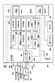
- FIG. 4 is a diagram illustrating a functional configuration of the limb compression device 100.
- the limb compression device 100 includes pressure control units 400, 410, 420, and 430, a battery 126 for power supply, a power switch 125, a control unit 440, an operation input unit 109, and a display unit 103.
- the control unit 440 is executed by an A / D converter 441-1 having eight or more input channels, an A / D converter 441-2 having four or more input channels, a CPU such as a microcomputer, and a CPU.
- a ROM for storing the control program and various data of the entire apparatus, a RAM for temporarily storing measurement data and various data as a work area, and the like are provided.
- the A / D converter 441-1 converts the pressure detection unit 403 and the K sound detection unit 409, and the A / D converter 441-2 converts the analog signal from the connection sensor 408 into a digital signal that can be processed by the CPU. To do.
- the control system which has a control part for every pressure unit may be sufficient. Absent.
- the pressure control units 400 to 430 are provided in a number corresponding to the number of cuff parts (301 to 304) that are pressure control objects, and the cuff parts, cuff tubes, and pressure control units constitute independent cuff systems. To do. That is, the pressure control units 400 to 430 are configured to be able to perform pressure control separately for each cuff unit based on an instruction from the control unit 440 that performs processing and determination in each processing flow.
- the four cuff systems have the same configuration, and therefore the pressure control units 400 to 430 have the same configuration. Therefore, hereinafter, the pressure control unit 400 that performs pressure control of the cuff unit 301 will be described.
- 401 is a connector portion, and a connector (not shown) at the rear end of the cuff tube 111 with the cuff portion 301 attached to the tip is detachably connected.
- Reference numeral 408 denotes a connection sensor.
- the connection sensor 408 sends a constant current to the resistor 133 indicating the cuff size built in the connector of each cuff shown in FIG.
- Each cuff part is provided with a detector for detecting a pulsation on the distal side with respect to a site compressed by the cuff part, and in this embodiment, a Korotkoff sound (hereinafter also referred to as a K sound) is acquired.
- Microphone microphone
- the signal line of the microphone 311 included in the cuff unit 301 is connected to the K sound detection unit 409 of the pressure control unit 400 via the connector unit 401.
- the K sound detection unit 409 detects the K sound from the sound acquired by the microphone 311 and notifies the control unit 440 of it.
- the K sound is used to detect the pulsation on the peripheral side of the portion compressed by the cuff part 301.
- the present invention is not limited to this, and any known technique such as an ultrasonic wave or an infrared ray is used. May be used.
- the 402 is a pressure transducer, which is connected to the connector 401 via an air pipe.
- the pressure converter 402 detects the air pressure in the cuff part 301 and converts it into an electrical signal.
- a pressure detection unit 403 amplifies the electric signal output from the pressure transducer 402 and transmits the amplified signal to the control unit 440 as a cuff pressure signal (pressure value P).
- the constant speed exhaust valve 404a is a constant speed exhaust valve which is one of the exhaust means, and is connected to the connector 401 through an air pipe.
- the constant speed exhaust valve 404a is used to reduce the pressure of the cuff portion 301 during ischemia at a specified fine speed and at a specified pressure reduction speed during the blood pressure measurement operation.
- Reference numeral 404b denotes an exhaust valve as a quick exhaust means, which is connected to the connector portion 401 via an air pipe in the same manner as the constant speed exhaust valve 404a.
- the exhaust valve 404b is configured to rapidly exhaust the air in the cuff portion 301 in order to switch the peripheral side of the compression site from the ischemic state (pressed state) to the perfusion state (release state) in which blood is perfused, and blood pressure.
- the pressure control unit 400 is provided with two types of exhaust valves, an exhaust valve 404b having a large exhaust amount per unit time and an exhaust valve 404a for controlling the exhaust amount per unit time to be small and constant. It is configured to be used by switching according to the treatment state of the short-term repeated ischemia treatment.
- the valve drive unit 405a controls the opening area of the constant speed exhaust valve 404a based on an instruction from the control unit 440, and the valve drive unit 405b controls opening / closing of the exhaust valve 404b based on an instruction from the control unit 440.
- Reference numeral 406 denotes a pump drive unit that controls the drive / stop of the pump 406 and the pressurization speed based on an instruction from the control unit 440.
- a silencer 406a reduces the drive sound and pulsation of the pump 406, and prevents the microphone 311 from detecting the pump drive sound and pulsation and erroneously detecting it as a K sound.
- the control unit 440 stores a program for executing a remote short-time repetitive ischemia process, which will be described later, and includes a cuff switch 104, a setting switch 105, set value increase / decrease switches 106 and 107, and a manual switch 108. Based on an instruction from the operation input unit 109 and an output from the pressure detection unit 403, the valve driving units 405a and 405b, the pump driving unit 407, the display unit 103, and the like are controlled.
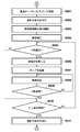
- FIGS. 5A, 5B, 6 to 8A, and 8B are flowcharts showing the flow of RICM processing that is executed in the control unit 440 of the limb compression apparatus 100.
- FIG. 5A, 5B, 6 to 8A, and 8B are flowcharts showing the flow of RICM processing that is executed in the control unit 440 of the limb compression apparatus 100.
- step S102 the automatic mode display 210 is turned on and set to operate in the automatic mode. If the manual switch 108 has been pressed, the manual mode display 211 is lit in step S103, and the manual mode is set. Subsequently, the process proceeds to step S803 (FIG. 8A), the apparatus enters the setting mode, and ischemia time, perfusion time, and ischemic pressure can be set by the setting switch 105 and the set value increase / decrease switches 106 and 107.
- FIGS. 5A and 5B show processing at the time of the first pressurization in the RICM processing automatic mode.
- automatic mode display is performed in step S102.
- the control unit 440 performs various initial settings. Specifically, the initial pressure is set to zero, and various timers (for example, a timer (t3) for measuring pressurization time, a timer (t1) for measuring ischemic time, a timer for measuring perfusion time, etc. (T2)) is reset. Further, the repressurization number counter KT is set to zero.
- the timer (t 3) is set to a specified value recorded in advance in the ROM of the control unit 440 because there is a difference in the capacity of the cuff air bag depending on the cuff size identified by the connection sensor 408.
- the S size is automatically set by changing the set value to a specified value smaller than the specified value in the case of the M size, and the L size is set to a larger specified value.
- the timer (t3) is set to a fixed value, and the cuff pressurization speed is set to a slow cuff pressurization speed for the S size and the cuff pressurization speed for the L size to the cuff pressurization speed specified for the M size. You may set to a pressurization speed.
- step S502 the control unit 440 starts receiving the cuff pressure value output from the pressure detection unit 403 via the A / D converter 441-1 and starts displaying on the cuff pressure display 207 of the display unit 103. At the same time, reception of the K sound detection signal from the K sound detection unit 409 is started.
- step S503 the control unit 440 instructs the valve drive units 405a and 405b to fully close the constant speed exhaust valve 404a and the exhaust valve 404b.
- step S504 the control unit 440 instructs the pump drive unit 407 to drive the pump 406.
- the pump drive unit 407 controls the rotation speed of the pump 406 by PWM control, and can control the pressurization speed.
- driving is started in step S504 (that is, in the pressurization process)
- the driving is controlled with a duty ratio of 100% until the cuff pressure reaches a first specified value (for example, 40 mmHg).
- a first specified value for example, 40 mmHg
- step S504 When pressurization of the cuff unit 301 by the pump 406 is started in step S504, the control unit 440 starts a pressurization time timer (t3) in step S505. As described above with reference to FIG. 4, the control unit 440 detects the size (one of S, M, and L) of the cuff connected based on the output value of the connection sensor 408. Then, the pressure value P of the cuff part 301 did not rise to the first specified value (40 mmHg in this embodiment) within a first specified time (for example, 15 seconds) preset for each cuff size. In this case, it is assumed that there is an abnormality in the pump 406 and the processing by the cuff unit is stopped.
- a first specified time for example, 15 seconds
- step S506 the control unit 440 determines whether or not the pressurization time timer value (t3) is equal to or longer than the first specified time (15 seconds in the present embodiment).
- t3 the pressurization time timer value
- the control unit 440 determines whether or not the pressure value P detected by the pressure detection unit 403 is equal to or higher than a first specified value (for example, 40 mmHg). If it is determined that “P ⁇ first specified value”, the process proceeds to step S508; otherwise, the process returns to step S506.
- a first specified value for example, 40 mmHg
- step S508 the control unit 440 continues to pressurize the cuff unit 301 by the pump 406, and the pressure value P becomes equal to or higher than the second specified value (for example, 180 mmHg in this embodiment). wait. If the pressure value P is equal to or greater than the second specified value, the process proceeds to step S509, and the control unit 440 instructs the pump drive unit 407 to stop the pump 406.
- step S510 the control unit 440 instructs the valve driving unit 405a to open the constant speed exhaust valve 404a and starts constant speed pressure reduction (2 to 3 mmHg / sec) of the cuff unit 301.
- the control unit 440 monitors the detection of the K sound by the K sound detection unit 409 while performing constant speed pressure reduction of the cuff unit 301 (step S511), and when the K sound is detected, the process proceeds to step S513.
- the control unit 440 Upon detection of insufficient pressurization in step S513, the control unit 440 confirms whether or not the K sound has been detected earlier than the specified time (within 1.5 seconds) after starting the pressure reduction, and the K sound is determined earlier than the specified time. If it is determined that the cuff pressure is detected, it is determined that the cuff pressure is too low to measure the systolic blood pressure, and the pressurization is insufficient. In the case of insufficient pressurization, the control unit 440 checks whether or not the number of times of insufficient pressurization is the second time in Step S519 (checks whether or not the value of the repressurization number counter KT is 1).
- step S801 the control unit 440 instructs the valve drive unit 405b to open the exhaust valve 404b and interrupts the operation.
- the control unit 440 changes the second specified value to 220 mmHg (step S520), counts up KT (step S521), and turns off the exhaust valves 404a and 404b again. Close (step S522) and start the pump (step S523). Then, the process returns to step S508.
- step S511 it is determined that the K sound has been detected when two consecutive beats of the K sound are acquired (step S511).
- the pressure value P becomes smaller than the third specified value (for example, 70 mmHg: lower limit value of normal systolic blood pressure) without detecting the K sound (YES in S512)
- the pump is normal but K
- step S801 the mode is switched to the manual mode, the pressure value during ischemia is manually set, and the RICM process without using the K sound is executed.
- step S511 If the K sound is detected in two consecutive beats in step S511 and it is determined in step S513 that the pressurization is not insufficient, the control unit 440 determines the cuff pressure value P when the K sound is first detected in step S514. Set to SBP. By such processing, a pressure value corresponding to the patient's systolic blood pressure value is automatically set in the SBP. Then, the control unit 440 instructs the valve drive units 405a and 405b to close the exhaust valves 404a and 404b (step S515), and instructs the pump drive unit 407 to start the pump (step S516).
- control unit 440 pressurizes until the pressure value P of the cuff unit 301 becomes SBP + 20 mmHg, stops the pump 406 (steps S517 and S518), and shifts to the ischemic period processing (processing after S601).
- 20 mmHg was shown as a predetermined value added to SBP, it is not restricted to this.
- the systolic blood pressure value of the patient is automatically measured, and in the ischemic period, a pressure value that is higher than the measured systolic blood pressure value by a predetermined pressure (20 mmHg in this example).
- a predetermined pressure (20 mmHg in this example).
- an appropriate pressure value (systolic blood pressure + 20 mmHg) of the cuff part 301 is automatically set according to the blood pressure state of the patient, and reliably in the vicinity of the patient's systolic blood pressure. It can be an ischemic state.
- step S531 the control unit 440 instructs the pump drive unit 407 to immediately stop driving the pump 406.
- step S532 the control unit 440 instructs the valve drive unit 405a to fully open the constant speed exhaust valve 404a, and instructs the valve drive unit 405b to fully open the exhaust valve 404b.
- step S533 the control unit 440 causes the pump abnormality display 208 to blink. At this time, if another cuff display is selected by the cuff changeover switch 104, the display is automatically switched to the corresponding cuff display to notify the pump abnormality.
- the controller 440 starts to press the cuff unit 301 by starting the driving of the pump 406, the cuff pressure in the cuff unit 301 is monitored. If the cuff pressure does not reach the first specified value within the first specified time, it is determined that there is a connection failure of the rear end connector of the cuff tube 111, an air leak, or an abnormal pump function. Then, the driving of the pump 406 is stopped and an alarm is output to the user. Thereby, the user can detect the abnormality of the pump and the K sound detection system in the pressurization process at an early stage.
- the apparatus controls the pressure using the K sound when the K sound cannot be detected or the disappearance of the K sound cannot be detected even though a sufficient pressure value is obtained within the first specified time. Without performing the operation, it operates in the manual mode in which the operation using the manually set ischemic pressure value is performed. The processing in this mode will be described later with reference to the flowcharts of FIGS. 8A and 8B.
- FIG. 6 is a flowchart for explaining processing during the ischemic period.
- the control unit 440 starts an ischemia timer (t1) for measuring an ischemia time.
- the control unit 440 lights the ischemia display 203 of the display unit 103 to notify the user that the ischemia is being performed.
- the control unit 440 starts displaying the remaining time until ischemia is completed on the remaining time display 205 of the display unit 103 based on the timer value (t1) of the ischemia timer.
- the remaining time is calculated by subtracting the timer value (t1) of the ischemic timer from a predetermined ischemic time or an ischemic time set by the user using the operation input unit 109.
- step S604 the control unit 440 instructs the valve drive unit 405a to start the slow exhaust (0.1 to 0.5 mmHg / second) by the constant speed exhaust valve 404a.
- step S605 the control unit 440 starts the K sound. Perform detection.
- the control unit 440 detects whether the timer value (t1) is equal to or longer than the set ischemic time.
- step S606 the control unit 440 instructs the valve drive unit 405a to close the constant speed exhaust valve 404a (step S606), and starts the pump (step S607).
- step S608 Slow pressurization is performed at a pressurization rate of about 2 to 3 mmHg / sec (step S608). At this time, the noise of the pump is extinguished by the silencer 406a and does not hinder the detection of the K sound.
- control unit 440 checks whether the K sound has disappeared. As a method for detecting the disappearance of the K sound, for example, if the K sound is continuously detected twice for 1.5 seconds, which is one cycle of the normal minimum pulse rate of 40 beats / minute, the K sound is not detected for 3 seconds. Is determined to be extinguished. Of course, the determination method is not limited to this. For example, the average period of the K sound detected so far may be calculated, and the case where the sound is not detected twice continuously during the average period may be determined as the disappearance of the K sound.
- step S608 If the disappearance of the K sound is not detected, the process returns to step S608, and the slow speed pressurization and the disappearance detection of the K sound are continued. If the disappearance of the K sound is detected, the process moves to step 610 to check whether or not the set ischemic time has come.
- the control unit 440 monitors the K sound and the pressure value P, and controls the pump drive unit 407 and the valve drive unit 405 so that the ischemic pressure is maintained at (SBP + 10 mmHg or less) as a result.
- step S610 When the timer value (t1) of the ischemia timer becomes equal to or greater than the ischemia time (step S610), the process proceeds to step S611, and the control unit 440 turns off the ischemia display 203. And a process progresses to step S701 of FIG. 7, and the process of a perfusion period is started.
- control unit 440 performs ischemia while maintaining the cuff pressure value slightly higher than the patient's systolic blood pressure value during the ischemic period, thereby reducing the burden on the patient due to the treatment.
- FIG. 7 is a flowchart showing processing during the perfusion period.
- the control unit 440 instructs the valve drive unit 405 to fully open the constant speed exhaust valve 404a and the exhaust valve 404b.
- the exhaust valve 404b is fully opened in addition to the constant speed exhaust valve 404a.
- the cuff part 301 can be decompressed at high speed.
- step S702 the control unit 440 determines whether or not the cuff pressure value output from the pressure detection unit 403 is equal to or less than 15 mmHg. If it is determined in step S702 that the cuff pressure value is not 15 mmHg or less, the process waits until the cuff pressure value is 15 mmHg or less.
- step S702 when it is determined that the cuff pressure value is 15 mmHg or less, the process proceeds to step S703.
- the control unit 440 starts a perfusion timer (t2) for measuring the perfusion time.
- the control unit 440 lights the perfusion display 204 to notify the user that the perfusion is in progress.
- the control unit 440 starts displaying the remaining time until the perfusion is completed in the remaining time display area 205 of the display unit 103 based on the timer value (t2) of the perfusion timer. The remaining time is calculated by subtracting the timer value (t2) of the perfusion timer from a predetermined perfusion time (for example, 5 minutes).
- step S706 the control unit 440 determines whether or not the timer value (t2) of the perfusion timer is equal to or longer than a predetermined perfusion time or a perfusion time (for example, 5 minutes) set by the operation input unit 109. To do. If the timer value (t2) does not reach the set perfusion time (for example, 5 minutes) in step S706, the process returns to step S705 to calculate and display the remaining perfusion time. Thereby, the perfusion of the set perfusion period is implemented.
- step S706 If it is determined in step S706 that the timer value (t2) has been set in advance or has reached the perfusion time (for example, 5 minutes) set by the operation input unit 109, the control unit 440 proceeds to step S707. To turn off the perfusion display 204. In step S708, the control unit 440 increments the cycle number S (assuming that zero is input as the initial value to the count value of the cycle number). Further, the process proceeds to step S709, and the control unit 440 displays the remaining cycle number in the remaining cycle number display area 206 of the display unit 103. The remaining cycle number is calculated by subtracting the counted current cycle number S from a predetermined number or the number set by the operation input unit 109 (four cycles in this embodiment).
- step S710 the control unit 440 determines whether or not the counted cycle number S is larger than the specified value (four cycles in the present embodiment), and if it is determined that it is less than the specified value, In order to return to the ischemic state, the process proceeds to step S711. On the other hand, if it is determined in step S710 that the cycle number S is greater than or equal to the specified value, the RICM process is terminated.
- step S711 the control unit 440 instructs the valve drive units 405a and 405b to fully close the constant speed exhaust valve 404a and the exhaust valve 404b.
- step S ⁇ b> 712 the control unit 440 instructs the pump driving unit 407 to drive the pump 406 and starts pressurization to the compression site by the cuff unit 301.
- the pressurization speed at this time is equal to the pressurization speed in step S504.
- the control unit 440 stops the pump and returns the process to step S601. Period processing is performed (steps S713 and S714).
- the above processing is processing for maintaining the ischemic pressure during the ischemic period at a pressure suitable for the patient using the K sound.
- the ischemic pressure is manually set and the RICM is set.
- the control unit 440 instructs the valve drive units 405a and 405b to release the pressurization by fully opening the constant speed exhaust valve 404a and the exhaust valve 404b, and in step S802, the K sound detection abnormality display 209 is displayed.
- control unit 440 causes the user to input ischemic pressure (hereinafter, manually set ischemic pressure value is referred to as SBPX) using set value increase / decrease switches 106 and 107.
- SBPX manually set ischemic pressure value
- the display unit 103 displays another cuff system or an item other than the ischemic pressure is selected as a setting item of the set value increase / decrease switches 106 and 107, automatically, You may make it switch to the input state of the ischemic pressure of a corresponding cuff type
- step S811 the control unit 440 instructs the valve drive unit 405a to close the constant speed exhaust valve 404a, and instructs the valve drive unit 405b to close the exhaust valve 404b.
- step S812 the control unit 440 instructs the pump driving unit 407 to start the pump 406, and the pressure value P of the cuff unit 301 detected by the pressure detection unit 403 is greater than or equal to SBPX input in step S804. Wait (step S813). Note that the pressurization speed at this time is equivalent to the pressurization speed started in step S504.
- the process proceeds from step S813 to step S814, and the control unit 440 instructs the pump drive unit 407 to stop the pump 406.
- the control unit 440 activates the ischemia timer (t1) in step S815, and turns on the ischemia display 203 in step S816.
- step S817 the control unit 440 starts displaying the remaining time until ischemia is completed in the remaining time display area 205 of the display unit 103 based on the timer value (t1) of the ischemia timer.
- This display process is the same as that in step S602.
- step S818 the process waits until the timer value (t1) is equal to or greater than the ischemic time, and maintains the ischemic state.
- the cuff pressure value P is monitored, and the pump drive unit 407 and the valve drive units 405a and 405b are controlled so that the pressure value is maintained in the vicinity of the set ischemic pressure (SBPX). Also good.
- step S819 When the timer value (t1) of the ischemia timer is equal to or greater than the ischemia time, the process proceeds to step S819, and the control unit 440 turns off the ischemia display 203. And a process progresses to step S821 and the process of a perfusion period is started.
- the process of the perfusion period shown in steps S821 to S830 is the same as the process of the perfusion period described for steps S701 to S710 in FIG.
- step S830 if the number of cycles S is equal to or greater than the specified value (4 in the present embodiment), the process ends. Otherwise, the process returns to step S811, and ischemia period processing of the next cycle Migrate to
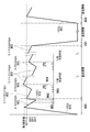
- FIG. 9 is a diagram for explaining pressure control by the limb compression device 100 during RICM processing.
- the cuff pressure of the cuff part 301 is raised to the second specified value by the first pressurization (901, S508), and then the cuff part 301 is depressurized at 2 to 3 mmHg / s to produce a K sound.
- the detection of the K sound by the detection unit 409 is monitored.
- the pressure value P at that time is held as SBP1 (Systolic Blood Pressure), and the pressure of the cuff part 301 is once increased to SBP1 + 20 mmHg. Thereafter, the K sound is monitored while the pressure is reduced at a low speed (0.1 to 0.5 mmHg / second).
- FIG. 9 shows changes in cuff pressure control when the systolic blood pressure fluctuates higher than the first (SBP1) (SBP2) and fluctuates low (SBP3).
- SBP1 SBP2
- SBP3 fluctuates low
- a cuff pressure higher by about 2 to 8 mmHg in 3 seconds than the measured systolic blood pressure when the pulse rate is 60 beats / minute is set as the ischemic pressure.
- the ischemic pressure may be increased by increasing the cuff pressure to a pressure obtained by adding an arbitrary numerical value.
- ischemic time and perfusion time are set to optimum values according to the patient's condition, and therefore the pressurization or depressurization time (920, 921, 922) between the ischemic condition and the perfusion condition is as much as possible. Short is desirable. That is, it is desirable that the pressure control during the state transition between the ischemic state and the perfusion state is configured as a highly responsive system.
- the ischemic pressure be set to an optimum value according to the patient's condition so that the burden on the patient is minimized, in addition to maintaining the ischemic state. It is desirable to control so as to maintain an appropriate ischemic pressure depending on the condition. Under such circumstances, in the limb compression apparatus 100 according to the present embodiment, the ischemic pressure is set to a pressure value (approximately SBP + 10 mmHg or less) slightly higher than the systolic blood pressure of the patient. Like to maintain. FIG. 9 shows a state in which the pressure value of the cuff part 301 is monitored during the ischemic period and the pressure value of the cuff part 301 is controlled to fall within a predetermined range of the ischemic pressure value.
- a pressure value approximately SBP + 10 mmHg or less
- the ischemic state is maintained and the blood pressure of the patient (systolic blood pressure value) is considered.
- the setting that minimizes the burden on the patient can be performed, and an appropriate limb compression operation according to the setting can be realized.
- a limb compression device that can maintain and manage an ischemic state and can realize a limb compression operation that minimizes the burden on the patient.
- the pressure control is performed independently for each. It is not limited to this.
- the number of cuff parts may be four or more or less than four.
- the exhaust valve used for slow pressure reduction in the ischemic state and the exhaust valve used in the pressure reduction process for shifting from the ischemic state to the perfusion state are separately arranged.
- the present invention is not limited to this.
- the valve opening degree may be changed between the ischemic state and the decompression process, and the exhaust valve may be configured by one exhaust valve.
- the completely independent control is performed for each cuff system, but the present invention is not limited to this.
- SBP obtained by another cuff system among a plurality of cuff systems may be used.
- the K sound detection unit may be provided only in the cuff system of the left upper limb, and the coefficient may be applied to the measurement result to determine the SBP of the left and right lower limbs or the upper right limb.
- a cuff system that cannot detect the K sound cannot detect fluctuations in systolic blood pressure during the ischemic period, so that the ischemic pressure value based on the systolic blood pressure determined as described above is maintained and ischemic. Will do.
Landscapes
- Health & Medical Sciences (AREA)
- Life Sciences & Earth Sciences (AREA)
- Veterinary Medicine (AREA)
- Animal Behavior & Ethology (AREA)
- General Health & Medical Sciences (AREA)
- Public Health (AREA)
- Surgery (AREA)
- Medical Informatics (AREA)
- Heart & Thoracic Surgery (AREA)
- Molecular Biology (AREA)
- Biophysics (AREA)
- Biomedical Technology (AREA)
- Engineering & Computer Science (AREA)
- Vascular Medicine (AREA)
- Cardiology (AREA)
- Epidemiology (AREA)
- Rehabilitation Therapy (AREA)
- Physical Education & Sports Medicine (AREA)
- Pain & Pain Management (AREA)
- Reproductive Health (AREA)
- Hematology (AREA)
- Nuclear Medicine, Radiotherapy & Molecular Imaging (AREA)
- Physiology (AREA)
- Physics & Mathematics (AREA)
- Pathology (AREA)
- Measuring Pulse, Heart Rate, Blood Pressure Or Blood Flow (AREA)
- Massaging Devices (AREA)
- Surgical Instruments (AREA)
Abstract
患者の肢部に巻かれるカフ部が接続され、カフ部の給気及び排気を制御することで肢部の圧迫と解放を制御する肢部圧迫装置は、カフ部への給気を制御することにより前記肢部を設定された虚血圧力値で圧迫し、予め定められた虚血時間にわたって圧迫部位よりも末梢側を虚血状態とする虚血期間と、カフ部の排気を制御して肢部の圧迫を解放し、予め定められた潅流時間にわたって虚血状態となった末梢側に血液を潅流させる潅流期間とを、所定回数繰り返す。肢部圧迫装置は、カフ部による圧迫部位よりも末梢側の拍動を検出する検出部を有し、拍動の検出によって測定された患者の収縮期血圧に基づく虚血圧力値までカフ部による加圧を行う。また、虚血期間においては、カフ部を微速減圧しながら拍動を検出することで収縮期血圧を計測し、計測された収縮期血圧に基づく虚血圧力値までカフ部による加圧を行うことを繰り返す。
Description
本発明は、上肢及び/または下肢に対する圧迫状態と解放状態を制御することで、虚血状態(圧迫状態)と潅流状態(解放状態)とを繰り返す肢部圧迫装置とその制御方法に関するものである。
虚血性疾患の治療において、心筋虚血による心筋細胞への影響を軽減させることは不可欠な課題である。早期の再潅流は心筋を保護するために重要であり、一般に、血栓溶解剤を用いた処置が行われる。また、最近では、アンギオによる血管造影を行い、虚血部位を観察しながらカテーテルを用いて再潅流を行うPTCAによる処置も行われている。
早期の再潅流を実現するためのこれらの処置による効果は絶大であるが、一方で、心筋に対するダメージも大きい。具体的には、再潅流による心筋細胞への障害や炎症が発生することで、虚血障害部位が拡大してしまうといった問題(再潅流シンドローム)が生じることがあり、治療上の大きな課題となっている。
この原因は、心筋細胞が産生する活性酸素であり、この産生を抑えることが再潅流シンドロームの防止にとって重要である。
このような課題に対して、心筋への血液の再潅流を行う前に、虚血発生部位から離れた部位、例えば、上腕部や下肢部を圧迫状態と解放状態とし、虚血状態/潅流状態を繰り返すことで、虚血発生部位である心筋に対して害を与える活性酸素の発生を抑制する遠隔部短時間反復虚血法(Remote Ischaemic conditioning method、以下、RICM)が提案されている。
RICMによれば、反復刺激により細胞内媒介物質が細胞内変異、または細胞間変異を起こし、活性酸素の発生に寄与する酵素であるキナーゼの誘導を抑えることができる。また、心筋細胞のATPの代謝を抑え、心筋細胞内のミトコンドリアの機能を調整することで細胞活性が抑えられ、これにより、活性酸素の産生を抑えることが可能となる。
このような再潅流シンドロームを抑制するRICMを実現するための装置として、従来より、種々の肢部圧迫装置が提案されている。例えば、下記特許文献1には、虚血時間や潅流時間、虚血圧力等を任意に設定できる構成が開示されているとともに、虚血中の圧力を一定にするための制御が可能である旨、記載されている。
一方で、RICMによる処置は、患者への負担が大きいことから、RICMによる処置を行うにあたっては、患者の重症度を考慮しながら、患者への負担が最小となるように虚血時間、潅流時間、虚血圧力等を設定することが必要である。特に、虚血圧力は不必要に大きくせず、できるだけ小さい値にすることが患者の負担軽減に大きく寄与する。このために、きわめて精密に圧力をコントロールすることが可能な肢部圧迫装置が必要である。
一方、上記特許文献1の場合、患者への負担が小となるような設定できるように構成されているものの、虚血圧力を収縮期血圧より規定圧力高く設定することは開示されているが、収縮期血圧の変動に合わせた適切な肢部圧迫動作を実現するための具体的な構成までは記載されていない。また、患者の血圧値の上昇する変動には対応できるものの、患者の血圧値が下降した場合には対応できず、この場合の患者の負担は軽減できない。
本発明は上記課題に鑑みてなされたものであり、緊急時に全自動にて、確実な動作が可能であり、患者への負担を最小にして適切な圧力での肢部圧迫動作を実現可能な肢部圧迫装置を提供することを目的とする。
上記の目的を達成するために、本発明に係る肢部圧迫装置は以下のような構成を備える。即ち、
患者の肢部に巻かれるカフ部が接続され、該カフ部の給気及び排気を制御することで前記肢部の圧迫と解放を制御する肢部圧迫装置であって、
前記カフ部の給気及び排気を制御することにより前記肢部を、予め定められた虚血期間にわたって圧迫する圧迫手段と、
前記カフ部の排気を制御して、予め定められた潅流期間にわたって前記肢部の圧迫を解放する解放手段と、
前記圧迫手段による前記虚血期間と前記解放手段による前記潅流期間とを所定回数だけ繰り返す制御手段と、
前記カフ部による前記圧迫部位よりも末梢側の拍動を検出する検出手段と、を備え、
前記圧迫手段は、
前記検出手段による拍動の検出によって測定された前記患者の収縮期血圧に基づく虚血圧力値まで前記カフ部による加圧を行い、
前記虚血期間において、前記検出手段により拍動が検出されるまで前記カフ部を微速減圧させ、その後、拍動が消失するように前記カフ部を加圧することを繰り返す、ことを特徴とする。
患者の肢部に巻かれるカフ部が接続され、該カフ部の給気及び排気を制御することで前記肢部の圧迫と解放を制御する肢部圧迫装置であって、
前記カフ部の給気及び排気を制御することにより前記肢部を、予め定められた虚血期間にわたって圧迫する圧迫手段と、
前記カフ部の排気を制御して、予め定められた潅流期間にわたって前記肢部の圧迫を解放する解放手段と、
前記圧迫手段による前記虚血期間と前記解放手段による前記潅流期間とを所定回数だけ繰り返す制御手段と、
前記カフ部による前記圧迫部位よりも末梢側の拍動を検出する検出手段と、を備え、
前記圧迫手段は、
前記検出手段による拍動の検出によって測定された前記患者の収縮期血圧に基づく虚血圧力値まで前記カフ部による加圧を行い、
前記虚血期間において、前記検出手段により拍動が検出されるまで前記カフ部を微速減圧させ、その後、拍動が消失するように前記カフ部を加圧することを繰り返す、ことを特徴とする。
本発明によれば、虚血圧力の設定において、患者の収縮期血圧値に応じた圧力値を設定することができ、患者への負担が低減された肢部圧迫動作が実現可能となる。
本発明のその他の特徴及び利点は、添付図面を参照とした以下の説明により明らかになるであろう。なお、添付図面においては、同じ若しくは同様の構成には、同じ参照番号を付す。
添付図面は明細書に含まれ、その一部を構成し、本発明の実施の形態を示し、その記述と共に本発明の原理を説明するために用いられる。
本発明の一実施形態に係る肢部圧迫装置100の外観構成を示す図である。
肢部圧迫装置100の表示部に表示される表示画面の一例を示す図である。
肢部圧迫装置100を用いて、患者に対して、遠隔部短時間反復虚血法による処置を施す様子を示した図である。
肢部圧迫装置100の機能構成を示す図である。
肢部圧迫装置100における遠隔部短時間反復虚血処理の流れを示すフローチャートである。
肢部圧迫装置100における遠隔部短時間反復虚血処理の流れを示すフローチャートである。
肢部圧迫装置100における遠隔部短時間反復虚血処理の流れを示すフローチャートである。
肢部圧迫装置100における遠隔部短時間反復虚血処理の流れを示すフローチャートである。
、
肢部圧迫装置100における遠隔部短時間反復虚血処理の流れを示すフローチャートである。
肢部圧迫装置100による圧力制御を説明するための図である。
以下、本発明の各実施形態について図面を参照しながら説明する。
[第1の実施形態]
1.肢部圧迫装置の外観構成
はじめに、本発明の一実施形態に係る肢部圧迫装置100の外観構成について説明する。図1は、本発明の一実施形態に係る肢部圧迫装置100の外観構成を示す図である。
1.肢部圧迫装置の外観構成
はじめに、本発明の一実施形態に係る肢部圧迫装置100の外観構成について説明する。図1は、本発明の一実施形態に係る肢部圧迫装置100の外観構成を示す図である。
図1において、101はハウジングであり、側面には、右下肢部、左下肢部、右上腕部、左上腕部にそれぞれ巻き回される不図示のカフ部が取り付けられたカフチューブ111~114を接続するためのエアーコネクタ(不図示)とカフ装着時にカフの空気袋(不図示)の生体接触面側の四肢の末梢側に位置する側に配置されたK音マイクロフォン(不図示)に接続されているマイクロフォンコネクタ121~124が配されている。マイクロフォンコネクタ121~124は、マイクロフォンからの信号線131,132(信号線132はグランド線)、カフサイズが判別できるようにカフサイズ毎に設定した抵抗値の抵抗器133内蔵されている。抵抗器133の一端は信号線132に接続され、抵抗器133の他端はコネクタピンの所定の部位に接続されている。例えば、本実施形態では、カフサイズとしてS,M,Lの3種類が用意されており、抵抗器133の抵抗値は、Sサイズ:1KΩ、Mサイズ:10KΩ、Lサイズ:100KΩとする。後述するが、各カフ部、これと接続される接続センサ及びカフチューブ及びK音計測部、圧力検出部、圧力制御部は、独立して動作するカフ系を構成する。本実施形態では、4つのカフ系が設けられている。なお、カフ系は、必ずしも4つ設ける必要はない。
125は装置の電源を入り切りする電源スイッチである。102は遠隔部短時間反復虚血処理(以下、RICM処理)の開始/停止を指示するためのスイッチであり、1回の押圧により処理が開始され、再度の押圧により処理が停止するよう構成されている。103は表示部であり、RICM処理を実行するための各種設定値や、実行中の状態等が表示される。なお、表示部103に表示される表示画面の詳細は後述する。
109は操作入力部であり、複数のカフ系(カフチューブ111~114)の各々の情報への表示の切り替えを行ったり、各カフ系について虚血期間や潅流期間の長さである虚血時間/潅流時間の設定、虚血圧力の手動設定を行ったりするためのスイッチ群である。カフ切り替えスイッチ104は、4つのカフ系のいずれの情報を表示するかを切り替えるためのスイッチである。たとえば、設定スイッチ105をONすることで装置は設定モードになる。カフチューブ111のカフ系に関する異常情報、カフ圧力値、虚血圧力値が表示部103に表示され、カフ切り替えスイッチ104を押すたびに、カフチューブ112のカフ系→カフチューブ113のカフ系→カフチューブ114のカフ系→カフチューブ114のカフ系→カフチューブ111のカフ系…のように各カフの異常情報、カフ圧力値、虚血圧力値が切り替わる。ここで、虚血とは、カフ等で所定以上の圧力で押圧されて血流が流れてない状態である。
設定スイッチ105は、設定項目を虚血時間→潅流時間→虚血圧力→サイクル数→虚血時間のように順に切り替えるのに用いられるスイッチである。また、マニュアルスイッチ108はK音検出が不能な場合に、マニュアルモードに切り替える場合のスイッチである。マニュアルスイッチ108を押すと装置はマニュアルモードに変更され、マニュアルモード表示が点灯する。また、押すごとに、自動モード→マニュアルモード→自動モードの順にモードが切り替わる。設定値増減スイッチ106,107は、設定切り替えスイッチ105により選択された項目(虚血時間/潅流時間/虚血圧力/サイクル数)の設定値を増減するのに用いられるスイッチである。
2.表示画面の構成
次に、表示部103に表示される表示画面の一例について説明する。図2は、表示部103に表示される表示画面の一例を示す図であり、カフ切り替えスイッチ104により選択された一つのカフ系に関わる異常情報(ポンプ異常,K音検出異常)、カフ圧力値、虚血圧力値を示している。従って、図2に示す異常情報表示、カフ圧力値、虚血圧力値は、4つのカフ系のそれぞれについて独立したものである。
次に、表示部103に表示される表示画面の一例について説明する。図2は、表示部103に表示される表示画面の一例を示す図であり、カフ切り替えスイッチ104により選択された一つのカフ系に関わる異常情報(ポンプ異常,K音検出異常)、カフ圧力値、虚血圧力値を示している。従って、図2に示す異常情報表示、カフ圧力値、虚血圧力値は、4つのカフ系のそれぞれについて独立したものである。
図2において、201は設定された虚血時間、潅流時間を表示する表示領域であり、202は設定された虚血圧力を表示する表示領域である。また、203は虚血中であることを示す表示領域であり、虚血中に点灯する(以下、虚血中表示203)。204は潅流中であることを示す表示領域であり、潅流中に点灯する(以下、潅流中表示204)。205は残時間表示であり、虚血中であれば、虚血期間が完了するまでの残時間を表示し、潅流中であれば、潅流期間が完了するまでの残時間を表示する。また、210は自動設定モードで動作していることを示す表示(自動モード表示)であり、211はマニュアルで設定するモードで動作していることを示す表示(マニュアルモード表示)である。
206は残りのサイクル数を表示する残サイクル数表示領域である。なお、本実施形態に係る肢部圧迫装置は、虚血・潅流を1サイクルとして、4サイクル分動作した後に、自動的に停止するように構成されている。また、サイクル数は、RICMにおける反復を実施すべき所定回数であり、以下の説明では「4回」とするが、上述したように操作入力部109の操作によりユーザ設定が可能なものである。
207は現在のカフ圧力値を表示するカフ圧力表示である。なお、カフ部は、右下肢部用、左下肢部用、右上腕部用、左上腕部用の4種類が接続されるが、いずれのカフ部のカフ圧力値を表示するかは、上述したように、カフ切り替えスイッチ104の操作により表示対象のカフ系を切り替えることで選択することができる。表示領域212には、情報が現在表示されているカフ系の番号または右上腕、左上腕、右大腿、左大腿と装着部位名が表示される。
ポンプ異常表示208は、エアー漏れおよび肢部圧迫装置100の不具合を検出した場合に点滅し、その旨をユーザに報知する。また、K音検出異常表示209は、K音マイクロフォンの四肢の動脈位置からのズレを含め肢部圧迫装置100がK音検出機能に関わる異常を検出した場合に点滅し、その旨をユーザに報知する。
3.肢部圧迫装置の使用態様
次に、肢部圧迫装置100の使用態様について説明する。図3は、肢部圧迫装置100を用いて、患者に対して、遠隔部短時間反復虚血法による処置を施す様子を示した図である。
次に、肢部圧迫装置100の使用態様について説明する。図3は、肢部圧迫装置100を用いて、患者に対して、遠隔部短時間反復虚血法による処置を施す様子を示した図である。
図3に示すように、カフチューブ111の先端には右下肢部用のカフ部301が取り付けられており、図3の例では、カフ部301に設けられたK音検出用マイク311を末梢側にして、動脈上に位置して右足大腿部に装着されている。また、カフチューブ112の先端には左下肢部用のカフ部302が取り付けられており、図3の例では、カフ部302に設けられたK音検出用マイクを末梢側にして、動脈上に位置して左足大腿部に装着されている。同様に、カフチューブ113の先端には、左上腕部用のカフ部303が取り付けられており、カフ部303に設けられたK音検出用マイクを手側(末梢側)にして、動脈上に位置して、患者の左上腕部に装着されている。また、カフチューブ114の先端には右上腕部用のカフ部304が取り付けられており、カフ部304に設けられたK音検出用マイクを手側(末梢側)にして、動脈上に位置して患者の右上腕部に装着されている。なお、カフチューブ111~114には、K音検出用マイクへの信号線も設けられている。カフチューブ111~114の信号線の一端には、それぞれK音検出用マイク311,312,313,314(図4)が接続されており、他端にはコネクタ121,122,123,124が接続されている。これらカフチューブ111~114及び信号線が接続されたコネクタ121~124は、それぞれ圧力制御ユニット400,410,420,430(図4)が有するコネクタ部401および接続センサ408と着脱可能にすることが好ましい。
このように、本実施形態に係る肢部圧迫装置100では、患者の四肢をカフ部301~304を用いて空気圧で圧迫し、各圧迫部位より末梢側を虚血状態にできるように構成されている。
4.肢部圧迫装置の機能構成
次に、肢部圧迫装置100の機能構成について説明する。図4は、肢部圧迫装置100の機能構成を示す図である。図4に示すように、肢部圧迫装置100は、圧力制御ユニット400,410,420,430、電源用の電池126、電源スイッチ125、制御部440、操作入力部109、表示部103を備える。制御部440は、入力チャンネル数を8チャンネル以上有するA/D変換器441-1、入力チャンネル数を4チャンネル以上有するA/D変換器441-2、マイクロコンピュータなどのCPU、CPUにより実行される装置全体の制御プログラムや各種データを記憶するROM、ワークエリアとして測定データや各種データを一時的に記憶するRAM、などを備える。A/D変換器441-1は、圧力検出部403やK音検出部409、また、A/D変換器441-2は接続センサ408からのアナログ信号をCPUによる処理が可能なデジタル信号に変換する。尚、圧力制御ユニット4式(400~430)に対して1つの制御部(440)にて制御する例を示したが、各圧力ユニット毎に専用の制御部を有する制御方式であってもかまわない。
次に、肢部圧迫装置100の機能構成について説明する。図4は、肢部圧迫装置100の機能構成を示す図である。図4に示すように、肢部圧迫装置100は、圧力制御ユニット400,410,420,430、電源用の電池126、電源スイッチ125、制御部440、操作入力部109、表示部103を備える。制御部440は、入力チャンネル数を8チャンネル以上有するA/D変換器441-1、入力チャンネル数を4チャンネル以上有するA/D変換器441-2、マイクロコンピュータなどのCPU、CPUにより実行される装置全体の制御プログラムや各種データを記憶するROM、ワークエリアとして測定データや各種データを一時的に記憶するRAM、などを備える。A/D変換器441-1は、圧力検出部403やK音検出部409、また、A/D変換器441-2は接続センサ408からのアナログ信号をCPUによる処理が可能なデジタル信号に変換する。尚、圧力制御ユニット4式(400~430)に対して1つの制御部(440)にて制御する例を示したが、各圧力ユニット毎に専用の制御部を有する制御方式であってもかまわない。
圧力制御ユニット400~430は、圧力制御対象であるカフ部(301~304)の数に対応した数だけ設けられており、カフ部、カフチューブ、圧力制御ユニットによりそれぞれが独立したカフ系を構成する。すなわち、圧力制御ユニット400~430は、各処理フローにおいて処理・判断を行なう制御部440からの指示に基づいて、各カフ部ごとに別々に圧力制御できるよう構成されている。なお、4つのカフ系は同様の構成を有しており、従って各圧力制御ユニット400~430は同様の構成を有する。そのため、以下では、カフ部301の圧力制御を行う圧力制御ユニット400について説明する。
圧力制御ユニット400において、401はコネクタ部であり、カフ部301が先端に取り付けられたカフチューブ111の後端のコネクタ(不図示)が着脱可能に接続される。408は接続センサであり、カフチューブ111のコネクタが接続された場合に、このコネクタ内に実装されているカフサイズ毎に決められた抵抗値を有する抵抗器133の抵抗値(図1参照;例えばSサイズ:1KΩ,Mサイズ:10KΩ,Lサイズ:100KΩ)を検知し、制御部440に送信する。たとえば、接続センサ408は、図1に示す、各カフのコネクタ内に内蔵されているカフサイズを示す抵抗器133に定電流を流し、抵抗Rとマイナス(接地)極間の電圧値に変換し入力チャンネル数を4チャンネル以上有するA/D変換器441-2に供給し、これによりカフサイズが検出される。制御部440は、接続センサ408によって、接続されているカフサイズを検出するとともに、無限大の抵抗値が検出され、カフ部が接続されていないと判断したカフ系については、後述の遠隔部短時間反復虚血処理を実施しない。なお、各カフ部は、カフ部による圧迫部位よりも末梢側における拍動を検出するための検出器を備えており、本実施形態では、コロトコフ音(以下、K音ともいう)を取得するためのマイクロフォン(マイク)を有する。カフ部301が有するマイク311の信号線は、コネクタ部401を介して圧力制御ユニット400のK音検出部409に接続される。K音検出部409はマイク311により取得された音からK音を検出し、制御部440に通知する。なお、本実施形態では、カフ部301による圧迫部位よりも末梢側の拍動を検出するために、K音を用いるが、これに限られるものではなく、超音波、赤外線等の周知のいかなる手法を用いてもよい。
402は圧力変換器であり、空気配管を介してコネクタ部401に接続されている。圧力変換器402では、カフ部301内の空気圧を検出し、電気信号に変換する。403は圧力検出部であり、圧力変換器402より出力された電気信号を増幅し、カフ圧力信号(圧力値P)として制御部440に送信する。
404aは排気手段の一つである定速排気弁であり、空気配管を介してコネクタ部401に接続されている。定速排気弁404aは、虚血中のカフ部301の圧力を規定の微速度にて、また、血圧測定動作中には規定の減圧速度で減圧するために用いられる。404bは急速排気手段としての排気弁であり、定速排気弁404aと同様に、空気配管を介してコネクタ部401に接続されている。排気弁404bは、圧迫部位より末梢側を、虚血状態(圧迫状態)から、血液が潅流する潅流状態(解放状態)へ切り替えるべく、カフ部301内の空気を急速排気する場合、および、血圧の測定が終了したときの急速排気に用いられる。つまり、圧力制御ユニット400には、単位時間あたりの排気量の大きい排気弁404bと単位時間あたりの排気量を小さく一定に制御する排気弁404aの2種類の排気弁が配されており、遠隔部短時間反復虚血処理の処理状態に応じて、切り替えて使用される構成となっている。弁駆動部405aは制御部440からの指示に基づいて定速排気弁404aの開口面積を制御し、弁駆動部405bは制御部440からの指示に基づいて排気弁404bの開閉を制御する。
406はポンプであり、消音器406a、空気配管を介してコネクタ部401に接続されており、カフ部301内のカフ袋に給気する。407はポンプ駆動部であり、制御部440からの指示に基づいて、ポンプ406の駆動/停止、及び加圧速度を制御する。406aは消音器であり、ポンプ406の駆動音および、脈動を低減して、マイク311がポンプの駆動音および脈動を検出し、K音として誤検出することを防止する。
制御部440には、後述する遠隔部短時間反復虚血処理を実行するためのプログラムが格納されており、カフ切り替えスイッチ104,設定スイッチ105,設定値増減スイッチ106,107,マニュアルスイッチ108を含む操作入力部109からの指示や圧力検出部403からの出力に基づいて、弁駆動部405a、405b、ポンプ駆動部407、表示部103等を制御する。
5.遠隔部短時間反復虚血処理(RICM処理)の流れ
次に、肢部圧迫装置100の制御部440において実行されるRICM処理の流れについて説明する。図5A、図5B、図6~図8A,図8Bは、肢部圧迫装置100の制御部440において実行されるRICM処理の流れを示すフローチャートである。
次に、肢部圧迫装置100の制御部440において実行されるRICM処理の流れについて説明する。図5A、図5B、図6~図8A,図8Bは、肢部圧迫装置100の制御部440において実行されるRICM処理の流れを示すフローチャートである。
まず、開始/停止スイッチ102が押されると、図5AのステップS101にてマニュアルスイッチ108が押されているかがチェックされる。押されていない場合には、ステップS102にて、自動モード表示210を点灯させ、自動モードで動作するようにセットされる。マニュアルスイッチ108が押されている場合には、ステップS103にてマニュアルモード表示211が点灯し、マニュアルモードにセットされる。つづいて、処理はステップS803(図8A)に進み、装置は設定モードとなり、設定スイッチ105,設定値増減スイッチ106,107で虚血時間、潅流時間、虚血圧力の設定が可能となる。
また、図5A,5Bでは、RICM処理自動モードにおける、最初の加圧時の処理が示されている。自動モードが設定されている状態でユーザにより開始/停止スイッチ102が押圧されると、ステップS102にて自動モ-ド表示を行う。ステップS501において、制御部440は各種初期設定を行う。具体的には、初期圧力としてゼロ設定するとともに、各種タイマ(例えば、加圧時間を計測するタイマ(t3)、虚血時間を計測するためのタイマ(t1)、潅流時間を計測するためのタイマ(t2))をリセットする。また、再加圧回数カウンタKTをゼロにする。ここで、たとえばタイマ(t3)は、接続センサ408により識別したカフサイズによりカフ空気袋の容量に差があるため、予め制御部440のROMに記録されている規定値に設定される。Mサイズの場合の規定値に対してSサイズは小さい規定値、Lサイズは大きい規定値にそれぞれ設定値を変えて自動的に設定される。また別の方法としては、タイマ(t3)を固定値にして、カフの加圧速度をMサイズの規定のカフ加圧速度に対して、Sサイズは遅いカフ加圧速度、Lサイズは速いカフ加圧速度に設定しても良い。ステップS502において、制御部440は、A/D変換器441-1を経て圧力検出部403より出力されたカフ圧力値の受信を開始し、表示部103のカフ圧力表示207への表示を開始するとともに、K音検出部409からのK音検出信号の受信を開始する。
ステップS503において、制御部440は、弁駆動部405a,405bに指示して、定速排気弁404a及び排気弁404bを全閉する。ステップS504において、制御部440は、ポンプ駆動部407に指示して、ポンプ406を駆動する。なお、ポンプ駆動部407では、PWM制御によりポンプ406の回転数を制御しており、その加圧スピードを制御することが可能である。ステップS504において駆動を開始する場合には(つまり、加圧過程においては)、例えばカフ圧力が第1の規定値(例えば、40mmHg)になるまではデューティ比100%により駆動を制御する。これにより、カフ空気袋のデッドスペ-スを全速で給気するのでカフ部301を急速に加圧することができる。このポンプ406の駆動により、1回目の虚血状態への加圧が開始される。
ステップS504においてポンプ406によるカフ部301の加圧が開始されると、ステップS505において、制御部440は、加圧時間タイマ(t3)をスタートさせる。制御部440は、図4に関して上述したように、接続センサ408の出力値により接続されているカフのサイズ(S,M,Lのいずれか)を検出する。そして、カフのサイズ毎にあらかじめ設定された第1の規定時間(例えば15秒)内にカフ部301の圧力値Pが第1の規定値(本実施形態では40mmHgとする)まで上昇しなかった場合は、ポンプ406に異常があるものとして、当該カフ部による処理を中止する。すなわち、ステップS506において、制御部440は、加圧時間タイマ値(t3)が第1の規定時間(本実施形態では15秒)以上となったかどうかを判定する。ここで、「t3≧第1の規定時間」の場合は、ポンプの異常が発生したと判断して、ステップS531以降の処理に進む。「t3<規定時間」であれば、処理はステップS507に進む。ステップS507において、制御部440は、圧力検出部403で検出される圧力値Pが第1の規定値(例えば40mmHg)以上になったか否かを判定する。「P≧第1の規定値」と判定された場合、処理はステップS508に進み、そうでなければ処理はステップS506に戻る。
次に、ステップS508において、制御部440は、引き続きポンプ406によるカフ部301の加圧を行い、圧力値Pが第2の規定値(本実施形態では、例えば180mmHgとする)以上になるのを待つ。圧力値Pが第2の規定値以上になった場合、処理はステップS509へ進み、制御部440はポンプ駆動部407に指示してポンプ406を停止する。そして、ステップS510において、制御部440は弁駆動部405aに指示して定速排気弁404aを開いてカフ部301の定速減圧(2~3mmHg/秒)を開始する。制御部440は、カフ部301の定速減圧を行いながらK音検出部409によるK音の検出を監視し(ステップS511)、K音が検出されると処理をステップS513に進める。
ステップS513の加圧不足検出にて、制御部440は、減圧を開始してから規定時間(1.5秒以内)より早くK音が検出されたか否かを確認し、規定時間より早くK音が検出されたと判断された場合にはカフ圧が収縮期血圧を測定するには低すぎるとして加圧不足と判定する。加圧不足の場合、制御部440は、ステップS519にて加圧不足の回数が2度目か否かをチェックする(再加圧回数カウンタKTの値が1か否かがチェックされる)。KTが1以上のときにはK音を用いた自動モード動作ができないと判断し、マニュアルモードでの処理を実行するためにステップS801に処理が進む。ステップS801において、制御部440は、弁駆動部405bに指示して排気弁404bを開け、動作を中断する。他方、KTが0の場合には、制御部440は、例えば、第2の規定値を220mmHgに変えて(ステップS520)、KTをカウントUPし(ステップS521)、再度、排気弁404a、404bを閉じ(ステップS522)、ポンプを起動する(ステップS523)。そして、処理はステップS508に戻る。
なお、本実施形態では、連続した2拍のK音が取得された場合に、K音が検出されたと判断している(ステップS511)。一方、K音が検出されないまま圧力値Pが第3の規定値(例えば、70mmHg:通常収縮期血圧の下限値)よりも小さくなった場合(S512でYES)は、ポンプは正常であるがK音を用いた制御はできないとして、処理を図8AのステップS801へ進める。ステップS801以降では、マニュアルモードに切り替えて、虚血時の圧力値をマニュアル設定し、K音を用いないRICM処理を実行する。
ステップS511でK音が連続2拍検出され、ステップS513において加圧不足ではないと判定されると、制御部440は、ステップS514において、最初にK音が検出されたときのカフ圧力値PをSBPに設定する。このような処理により、患者の収縮期血圧値に相当する圧力値が自動的にSBPに設定されることになる。そして、制御部440は、弁駆動部405a,405bに指示して排気弁404a,404bを閉じ(ステップS515)、ポンプ駆動部407に指示してポンプを起動する(ステップS516)。こうして、制御部440は、カフ部301の圧力値PがSBP+20mmHgとなるまで加圧し、ポンプ406を停止し(ステップS517、S518)、虚血期間の処理(S601以降の処理)へと移行する。なお、SBPに加算される所定値として20mmHgを示したが、これに限られるものではない。
以上のような加圧処理によれば、自動的に患者の収縮期血圧値が測定され、虚血期間においては、測定された収縮期血圧値より所定圧力(本例では20mmHg)だけ高い圧力値でカフ部301による圧迫が実施されることになる。すなわち、本実施形態によれば、患者の血圧の状態に応じて、カフ部301の適切な圧力値(収縮期血圧+20mmHg)が自動的に設定され、患者の収縮期血圧の近傍で、確実に虚血状態とすることができる。
なお、ポンプ異常と判断された場合(ステップS506でYES)、ステップS531において、制御部440は、ポンプ駆動部407に指示して、ポンプ406の駆動を直ちに停止する。そして、ステップS532において、制御部440は、弁駆動部405aに指示して定速排気弁404aを全開にするとともに、弁駆動部405bに指示して排気弁404bを全開する。更に、ステップS533において、制御部440は、ポンプ異常表示208を点滅させる。このとき、カフ切り替えスイッチ104により別のカフ系の表示が選択されていた場合は、自動的に該当するカフ系の表示へ切り替えて、ポンプ異常の通知を行う。
このように、制御部440では、ポンプ406の駆動を開始することによりカフ部301の加圧を開始すると、カフ部301内のカフ圧力の監視を行う。そして、カフ圧力が第1の規定時間内に第1の規定値に到達しなかった場合には、カフチューブ111の後端のコネクタの接続不良または、エアー漏れ、ポンプ機能異常があると判断し、ポンプ406の駆動を停止させ、ユーザに警報出力する。これにより、ユーザは、加圧過程におけるポンプやK音検出系の異常を早期に検出することが可能となる。また、装置は、第1の規定時間内に十分な圧力値が得られたにもかかわらず、K音の検出や、K音の消失の検出ができない場合には、K音を用いた圧力制御を行わずに、マニュアルで設定された虚血圧力値を用いた操作をおこなうマニュアルモードで動作する。このモードの処理については、図8A,図8Bのフローチャートにより後述する。
図6は、虚血期間の処理を説明するフローチャートである。まず、ステップS601において、制御部440は、虚血時間を計測するための虚血タイマ(t1)をスタートさせる。そして、ステップS602において、制御部440は、表示部103の虚血中表示203を点灯させ、虚血中であることをユーザに報知する。ステップS603において、制御部440は、当該虚血タイマのタイマ値(t1)に基づいて、表示部103の残時間表示205に虚血が完了するまでの残時間を表示することを開始する。なお、残時間は、所定の虚血時間、或いはユーザにより操作入力部109を用いて設定された虚血時間から、虚血タイマのタイマ値(t1)を差し引くことで算出される。
ステップS604にて、制御部440は、弁駆動部405aに指示して定速排気弁404aにて、微速排気(0.1~0.5mmHg/秒)を開始し、ステップS605にてK音の検出を行う。K音が検出されない場合には、ステップS610において、制御部440は、タイマ値(t1)が設定した虚血時間以上になったかを検出する。一方、ステップS605にてK音が検出された場合には、制御部440は、弁駆動部405aに指示して定速排気弁404aを閉じ(ステップS606)、ポンプを起動し(ステップS607)、加圧速度が2~3mmHg/秒程度の微速加圧を行う(ステップS608)。このとき、ポンプのノイズは消音器406aで消されておりK音の検出に障害を与えない。ステップS609にて、制御部440は、K音が消滅したかどうかをチェックする。なお、K音の消滅検出方法としては、例えば、通常の最低脈拍数40拍/分の1周期である1.5秒間K音が続けて2度、都合3秒間検出されなかった場合にK音の消滅と判定することが挙げられる。もちろん、このような判定方法に限られるものではない。たとえば、今までに検出したK音の平均周期を計算し、平均周期間に連続2度検出されなかった場合をK音の消滅と判定するようにしても良い。
K音の消滅が検出されない場合にはステップS608に戻り、微速加圧およびK音の消滅検出を続ける。K音の消滅が検出された場合、処理はステップ610に移り、設定した虚血時間になったか否かがチェックされる。以上の様にして、制御部440は、K音および圧力値Pを監視して、結果として虚血圧力が(SBP+10mmHg以下)に維持されるようにポンプ駆動部407や弁駆動部405を制御する。虚血タイマのタイマ値(t1)が虚血時間以上になる(ステップS610)と、処理はステップS611に進み、制御部440は虚血中表示203を消灯する。そして、処理は図7のステップS701へ進み、潅流期間の処理が開始される。
このように、制御部440は、虚血期間の間、カフ圧力値を、患者の収縮期血圧値よりわずかに高い近傍で維持して虚血を行うので、処置による患者への負担が軽減される。
図7は、潅流期間の処理を示すフローチャートである。ステップS701において、制御部440は、弁駆動部405に指示して、定速排気弁404a及び排気弁404bを全開とする。このように、虚血期間が経過し、虚血状態から潅流状態へと移行するにあたっては、定速排気弁404aに加え、排気弁404bも全開させる。これにより、カフ部301を高速で減圧することが可能となる。
ステップS702において、制御部440は、圧力検出部403より出力されるカフ圧力値が、15mmHg以下となったか否かを判定する。ステップS702において、カフ圧力値が、15mmHg以下になっていないと判定された場合には、15mmHg以下となるまで待機する。
ステップS702において、カフ圧力値が、15mmHg以下になったと判定された場合には、処理はステップS703に進む。ステップS703において、制御部440は、潅流時間を計測するための潅流タイマ(t2)をスタートさせる。そして、ステップS704において、制御部440は、潅流中表示204を点灯させ、ユーザに対して潅流中であることを報知する。ステップS705において、制御部440は、潅流タイマのタイマ値(t2)に基づいて、表示部103の残時間表示領域205に潅流が完了するまでの残時間表示を開始する。なお、残時間は、予め定められた潅流時間(例えば、5分)から潅流タイマのタイマ値(t2)を差し引くことにより算出される。
ステップS706において、制御部440は、潅流タイマのタイマ値(t2)が、予め定められた潅流時間或いは操作入力部109により設定された潅流時間(例えば、5分)以上となったか否かを判定する。ステップS706において、タイマ値(t2)が設定された潅流時間(例えば、5分)に到らなければステップS705にもどり潅流残時間を計算表示する。これにより、設定された潅流期間の潅流が実施される。
ステップS706において、タイマ値(t2)が予め定められた、あるいは操作入力部109により設定された潅流時間(例えば、5分)以上になったと判定された場合には、制御部440は、ステップS707で潅流中表示204を消灯する。そして、ステップS708において、制御部440は、サイクル数Sをインクリメントする(なお、サイクル数のカウント値には、初期値としてゼロが入力されているものとする)。更に処理はステップS709に進み、制御部440は、表示部103の残サイクル数表示領域206に残サイクル数を表示する。なお、残サイクル数は予め定められた回数、あるいは操作入力部109により設定された回数(本実施形態では4サイクル)から、カウントされた現在のサイクル数Sを差し引くことで算出される。
ステップS710において、制御部440は、カウントされたサイクル数Sが、上記規定値(本実施形態では4サイクル)より大きいか否かを判定し、規定値未満であると判定された場合には、再び虚血状態とするために処理をステップS711に進める。一方、ステップS710においてサイクル数Sが規定値以上であると判定された場合には、RICM処理を終了する。
ステップS711において、制御部440は、弁駆動部405a,405bに指示して、定速排気弁404aと排気弁404bを全閉とする。そして、ステップS712において、制御部440は、ポンプ駆動部407に指示してポンプ406を駆動し、カフ部301による圧迫部位への加圧を開始する。なお、このときの加圧スピードは、ステップS504による加圧のスピードと同等とする。そして、制御部440は、圧力検出部403により検出される圧力値PがステップS514で設定されたSBPに20mmHgを加算した値以上になると、ポンプを停止して処理をステップS601に戻し、虚血期間の処理を行う(ステップS713、S714)。
以上の処理が、K音を用いて虚血期間の虚血圧を患者に適した圧力で維持する処理である。他方、K音(血圧測定結果)を用いた虚血圧力の設定ができないと判定された場合(ステップS512でYES、または、ステップS519でYES)には、マニュアルで虚血圧力を設定してRICM処理を実施する。図8A、図8Bはそのような処理を説明するフローチャートである。まず、制御部440は、ステップS801において、弁駆動部405a,405bに指示して定速排気弁404aと排気弁404bを全開として加圧を解除し、ステップS802において、K音検出異常表示209を点灯してアラーム表示をし、K音を用いることができないことをユーザに知らせる。そして、ステップS803において、制御部440は、ユーザに設定値増減スイッチ106、107を用いて虚血圧力(以下、マニュアル設定された虚血圧力値をSBPXとする)を入力させる。なお、このとき、表示部103が他のカフ系を表示していたり、設定値増減スイッチ106,107の設定項目として虚血圧力以外の項目が選択されていたりした場合には、自動的に、該当するカフ系の虚血圧力の入力状態に切り替わるようにしてもよい。
次に、ステップS811において、制御部440は、弁駆動部405aに指示して定速排気弁404aを、弁駆動部405bに指示して排気弁404bをそれぞれ閉じる。ステップS812において、制御部440は、ポンプ駆動部407に指示してポンプ406を起動し、圧力検出部403が検出するカフ部301の圧力値PがステップS804で入力されたSBPX以上となるのを待つ(ステップS813)。なお、このときの加圧スピードは、ステップS504で開始される加圧のスピードと同等とする。圧力値PがSBPX以上となると、処理はステップS813からステップS814へ進み、制御部440はポンプ駆動部407に指示してポンプ406を停止する。
制御部440は、ステップS815において虚血タイマ(t1)を起動し、ステップS816において虚血中表示203を点灯する。そして、制御部440は、ステップS817において、当該虚血タイマのタイマ値(t1)に基づいて、表示部103の残時間表示領域205に虚血が完了するまでの残時間の表示を開始する。なお、この表示処理は、ステップS602と同様である。そして、ステップS818において、タイマ値(t1)が虚血時間以上になるまで待機し、虚血状態を維持する。なお、この間、カフ圧力値Pを監視して、圧力値が設定された虚血圧力(SBPX)の近傍に維持されるようにポンプ駆動部407や弁駆動部405a,405bを制御するようにしてもよい。
虚血タイマのタイマ値(t1)が虚血時間以上になると、処理はステップS819に進み、制御部440は虚血中表示203を消灯する。そして、処理はステップS821へ進み、潅流期間の処理が開始される。ステップS821~S830に示される潅流期間の処理は、図7のステップS701~710について説明した潅流期間の処理と同様である。ステップS830において、サイクル数Sが規定値(本実施形態では4)以上であった場合には本処理を終了し、そうでなければ処理はステップS811に戻り、次のサイクルの虚血期間の処理へ移行する。
6.圧力制御の説明
次に、図5A、図5B、図6~図7のフローチャートにより上述した、K音(血圧測定結果)を用いたRICM処理時の、肢部圧迫装置100による圧力制御について説明する。図9は、RICM処理時の、肢部圧迫装置100による圧力制御を説明するための図である。
次に、図5A、図5B、図6~図7のフローチャートにより上述した、K音(血圧測定結果)を用いたRICM処理時の、肢部圧迫装置100による圧力制御について説明する。図9は、RICM処理時の、肢部圧迫装置100による圧力制御を説明するための図である。
図9に示すように、最初の加圧によりカフ部301のカフ圧力を第2の規定値まで上昇させ(901、S508)、その後、カフ部301を2~3mmHg/sで減圧してK音検出部409によるK音の検出を監視する。K音が検出されると(902、S511)、その時点の圧力値PをSBP1(Systolic Blood Pressure:収縮期血圧値)として保持し、カフ部301の圧力を一度SBP1+20mmHgまで加圧する。以降、微速減圧(0.1~0.5mmHg/秒)しながらK音の監視を行う。その後、K音が連続2拍検出された場合には(903)、血圧の変動によりカフ圧が虚血できない状態になったと判断し、2から3mmHg/秒の加圧速度でカフを加圧しながらK音を観察する(S605~S609)。そして、3秒間K音が連続して無いことを検出して適当な虚血状態であることを検出し、虚血状態に戻す(904)。その後、ふたたび制御部440は、弁駆動部405aに指示して定速排気弁404aを開き、微速減圧を開始し、K音を監視する。以上の制御を繰り返すことにより、K音を用いてSBPを計測しながら、SBPより少し高い(2拍分、最大10mmHg程度)圧力を虚血圧力とすることができる。図9に収縮期血圧が最初(SBP1)より高く変動した場合(SBP2)、および低く変動した場合(SBP3)のカフ圧力制御変化を示す。本例の場合、脈拍数が60拍/分の場合測定された収縮期血圧よりも3秒間にて約2から8mmHgだけ高いカフ圧力を虚血圧力と設定しているが、さらに、虚血の安定性を鑑みさらに任意の数値を加算した圧力までカフ圧を上げ虚血圧力にしても良い。
なお、虚血時間と潅流時間は、患者の状態に応じて最適な値が設定されるため、虚血状態と潅流状態との間の加圧または減圧の時間(920、921、922)は極力短いことが望ましい。つまり、虚血状態と潅流状態との間の状態遷移中の圧力制御は、応答性の高い系として構成されていることが望ましい。
一方、虚血状態の維持と合わせて、虚血圧力は、患者への負担が最小となるように、患者の状態に応じて最適な値とすることが望まれ、虚血期間中は、患者に応じた適切な虚血圧力が維持されるように制御されることが望ましい。このような状況のもと、本実施形態に係る肢部圧迫装置100では、虚血圧力を患者の収縮期血圧より少し高い圧力値(概ねSBP+10mmHg以下)に設定して、虚血期間中はこれを維持するようにしている。なお、図9では虚血期間中にカフ部301の圧力値を監視し、カフ部301の圧力値が虚血圧力値の所定範囲に収まるように制御されている様子が示されている。
以上の説明から明らかなように、本実施形態に係る肢部圧迫装置100では、RICM処理を実行するにあたり、虚血状態の維持管理、とともに患者の血圧(収縮期血圧値)の変動を考慮しながら、患者への負担が最小となるような設定を行うことができるとともに、当該設定に合わせた適切な肢部圧迫動作を実現することが可能となった。
つまり、虚血状態の維持管理ができて、かつ、患者への負担が最小となるような肢部圧迫動作を実現可能な肢部圧迫装置を提供することが可能となった。
[その他の実施形態]
なお、上記第1の実施形態では、右下肢部用、左下肢部用、右上腕部用、左上腕部用の4つのカフ部を用意し、それぞれを独立に圧力制御する構成としたが、これに限定されない。例えば、カフ部は4つ以上であっても、4つ未満であってもよい。
なお、上記第1の実施形態では、右下肢部用、左下肢部用、右上腕部用、左上腕部用の4つのカフ部を用意し、それぞれを独立に圧力制御する構成としたが、これに限定されない。例えば、カフ部は4つ以上であっても、4つ未満であってもよい。
また、上記第1の実施形態では、虚血状態において微速減圧に用いる排気弁と、虚血状態から潅流状態に移行するための減圧過程において用いる排気弁とをそれぞれ別々に配する構成としたが、本発明はこれに限定されない。例えば、虚血状態と減圧過程とで、弁開度を変更することで対応し、1台の排気弁により構成するようにしてもよい。
また、上記第1の実施形態では、カフ系ごとに完全に独立した制御を行ったが、これに限られるものではない。たとえば、圧迫部位より末梢側の拍動(実施形態ではK音)を検出できない場合に、複数のカフ系のうちの他のカフ系で得られたSBPを流用するようにしてもよい。この場合、たとえば、左下肢部であれば右下肢部の血圧値を流用するというように、もっとも収縮期血圧値が近いであろう部位のカフ系で得られたSBPを用いるようにするのが好ましい。或いは、右下肢部の血圧値に係数を乗じて右上肢部に流用するというように、部位間で適用すべき係数をあらかじめ設定しておいて、他の部位の血圧値を流用するようにしてもよい。従って、例えば、左上肢部のカフ系のみにK音検出部を設け、その測定結果に係数を適用して、左右下肢部や右上肢部のSBPを決定するように構成してもよい。ただし、K音を検出できないカフ系では虚血期間における収縮期血圧の変動を検出することができないので、上記のように決定された収縮期血圧に基づいた虚血圧力値を維持して虚血することになる。
本発明は上記実施の形態に制限されるものではなく、本発明の精神及び範囲から離脱することなく、様々な変更及び変形が可能である。従って、本発明の範囲を公にするために、以下の請求項を添付する。
本願は、2011年3月31日提出の日本国特許出願特願2011-078016を基礎として優先権を主張するものであり、その記載内容の全てを、ここに援用する。
Claims (7)
- 患者の肢部に巻かれるカフ部が接続され、該カフ部の給気及び排気を制御することで前記肢部の圧迫と解放を制御する肢部圧迫装置であって、
前記カフ部の給気及び排気を制御することにより、予め定められた虚血期間にわたって前記肢部を圧迫する圧迫手段と、
前記カフ部の排気を制御して、予め定められた潅流期間にわたって前記肢部の圧迫を解放する解放手段と、
前記圧迫手段による前記虚血期間と前記解放手段による前記潅流期間とを所定回数だけ繰り返す制御手段と、
前記カフ部による圧迫部位よりも末梢側の拍動を検出する検出手段と、を備え、
前記圧迫手段は、
前記検出手段による拍動の検出によって測定された前記患者の収縮期血圧に基づく虚血圧力値まで前記カフ部による加圧を行い、
前記虚血期間において、前記検出手段により拍動が検出されるまで前記カフ部を微速減圧させ、その後、拍動が消失するように前記カフ部を加圧することを繰り返す、ことを特徴とすることを特徴とする肢部圧迫装置。 - 前記圧迫手段は、1回目の虚血期間のための最初の加圧に際して、前記カフ部による圧迫を所定の圧力値まで行った後、前記カフ部を減圧して測定された収縮期血圧に基づいて虚血圧力値を決定し、
2回目以降の虚血期間のための最初の加圧では、前記1回目の虚血期間のための最初の加圧にて決定された虚血圧力値まで前記カフ部による加圧を行う、ことを特徴とする請求項1に記載の肢部圧迫装置。 - 前記虚血圧力値は、測定された収縮期血圧に所定値を加算した値である、ことを特徴とする請求項1または2に記載の肢部圧迫装置。
- 前記カフ部、前記圧迫手段、前記解放手段、前記制御手段、前記検出手段を具備したカフ系を複数有し、前記複数のカフ系の各々が独立して前記虚血期間と前記潅流期間の繰り返しを実行する、ことを特徴とする請求項1乃至3のいずれか1項に記載の肢部圧迫装置。
- 前記患者の収縮期血圧が測定できない場合に、虚血圧力値をユーザに設定させる設定手段を更に備え、
前記圧迫手段は、前記虚血期間において、前記カフ部のカフ圧力を前記設定手段で設定された虚血圧力値に維持する、ことを特徴とする請求項1乃至4のいずれか1項に記載の肢部圧迫装置。 - 前記患者の収縮期血圧が測定できない場合に、前記複数のカフ系のうちの他のカフ系で測定された収縮期血圧を用いて虚血圧力値を設定する設定手段を更に備え、
前記圧迫手段は、前記虚血期間において、前記カフ部のカフ圧力を前記設定手段で設定された虚血圧力値に維持する、ことを特徴とする請求項4に記載の肢部圧迫装置。 - 患者の肢部に巻かれるカフ部が接続され、該カフ部の給気及び排気を制御することで前記肢部の圧迫と解放を制御する肢部圧迫装置の制御方法であって、
前記カフ部の給気及び排気を制御することにより、予め定められた虚血期間にわたって前記肢部を圧迫する圧迫工程と、
前記カフ部の排気を制御して、予め定められた潅流期間にわたって前記肢部の圧迫を解放する解放工程と、
前記圧迫工程による前記虚血期間と前記解放工程による前記潅流期間とを所定回数だけ繰り返す制御工程と、
前記カフ部による圧迫部位よりも末梢側の拍動を検出する検出工程と、を有し、
前記圧迫工程では、
前記検出工程における拍動の検出によって測定された前記患者の収縮期血圧に基づく虚血圧力値まで前記カフ部による加圧を行い、
前記虚血期間において、前記検出工程において拍動が検出されるまで前記カフ部を微速減圧させ、その後、拍動が消失するように前記カフ部を加圧することを繰り返す、ことを特徴とすることを特徴とする肢部圧迫装置の制御方法
Priority Applications (1)
| Application Number | Priority Date | Filing Date | Title |
|---|---|---|---|
| US14/035,629 US20140024986A1 (en) | 2011-03-31 | 2013-09-24 | Limb compression device and control method |
Applications Claiming Priority (2)
| Application Number | Priority Date | Filing Date | Title |
|---|---|---|---|
| JP2011078016A JP5815261B2 (ja) | 2011-03-31 | 2011-03-31 | 肢部圧迫装置 |
| JP2011-078016 | 2011-03-31 |
Related Child Applications (1)
| Application Number | Title | Priority Date | Filing Date |
|---|---|---|---|
| US14/035,629 Continuation US20140024986A1 (en) | 2011-03-31 | 2013-09-24 | Limb compression device and control method |
Publications (1)
| Publication Number | Publication Date |
|---|---|
| WO2012132268A1 true WO2012132268A1 (ja) | 2012-10-04 |
Family
ID=46930062
Family Applications (1)
| Application Number | Title | Priority Date | Filing Date |
|---|---|---|---|
| PCT/JP2012/001684 Ceased WO2012132268A1 (ja) | 2011-03-31 | 2012-03-12 | 肢部圧迫装置および制御方法 |
Country Status (3)
| Country | Link |
|---|---|
| US (1) | US20140024986A1 (ja) |
| JP (1) | JP5815261B2 (ja) |
| WO (1) | WO2012132268A1 (ja) |
Cited By (5)
| Publication number | Priority date | Publication date | Assignee | Title |
|---|---|---|---|---|
| CN104000712A (zh) * | 2014-06-13 | 2014-08-27 | 广州阳普医疗科技股份有限公司 | 一种肢体缺血治疗仪及其控制方法 |
| WO2014167422A3 (en) * | 2013-03-15 | 2015-03-05 | Cellaegis Devices, Inc. | Gas powered system for performing remote ischemic conditioning |
| CN105361920A (zh) * | 2015-08-18 | 2016-03-02 | 兴山县人民医院 | 止血带 |
| CN111511274A (zh) * | 2017-12-27 | 2020-08-07 | 欧姆龙健康医疗事业株式会社 | 生物体信息测量装置、方法以及程序 |
| JP2021515625A (ja) * | 2018-03-05 | 2021-06-24 | ウエスタン クリニカル エンジニアリング リミテッド | 間欠性血管閉塞のための個人用止血帯 |
Families Citing this family (21)
| Publication number | Priority date | Publication date | Assignee | Title |
|---|---|---|---|---|
| US7717855B2 (en) | 2006-12-06 | 2010-05-18 | The Hospital For Sick Children | System for performing remote ischemic preconditioning |
| US8764789B2 (en) | 2011-04-15 | 2014-07-01 | CellAegis Devices Inc. | System for performing remote ischemic conditioning |
| WO2014081970A1 (en) | 2012-11-21 | 2014-05-30 | Medical Ingenuities, LLC | Radial compression hemostasis band with doppler confirming vascular patency |
| JP6351701B2 (ja) * | 2013-03-15 | 2018-07-04 | ライフカフ テクノロジーズ インコーポレイテッド | マルチモード膨張式肢部閉塞デバイス |
| CA2904162A1 (en) | 2013-03-15 | 2014-12-18 | The Hospital For Sick Children | Methods relating to the use of remote ischemic conditioning |
| WO2014140832A2 (en) | 2013-03-15 | 2014-09-18 | The Hospital For Sick Children | Treatment of erectile dysfunction using remote ischemic conditioning |
| CA2942614A1 (en) | 2013-03-15 | 2014-10-16 | The Hospital For Sick Children | Methods for modulating autophagy using remote ischemic conditioning |
| JP6143301B2 (ja) * | 2013-03-16 | 2017-06-07 | 博司 福田 | 駆血治療装置 |
| PL408619A1 (pl) * | 2014-06-20 | 2015-12-21 | Instytut Kardiologii Im. Prymasa Tysiąclecia Stefana Kardynała Wyszyńskiego | Sposób automatycznego tamowania krwi, system automatycznego tamowania krwi oraz opaska uciskowa |
| US9814467B2 (en) * | 2014-07-10 | 2017-11-14 | Western Clinical Engineering Ltd. | Personalized tourniquet apparatus |
| GB201419968D0 (en) * | 2014-11-10 | 2014-12-24 | Mjs Healthcare Ltd | Pressure cuff detection system |
| JP6410576B2 (ja) * | 2014-11-19 | 2018-10-24 | 日本光電工業株式会社 | 加圧制御装置および加圧制御方法 |
| CN104644147B (zh) * | 2014-12-26 | 2016-08-24 | 吉训明 | 一种缺血预适应治疗仪及其在判断血管健康状况的应用和方法 |
| US10335310B2 (en) * | 2015-03-16 | 2019-07-02 | Aliasghar Hariri | Apparatuses and methods for disrupting and preventing snore |
| WO2016200986A1 (en) | 2015-06-08 | 2016-12-15 | Corrigan Jr Richard F | Radial compression hemostasis band with doppler confirming vascular patency |
| FR3055204A1 (fr) * | 2016-08-30 | 2018-03-02 | Guillaume Lenormand | Procede d'aide au diagnostic pour detecter une anomalie de pression arterielle |
| CN106821450A (zh) * | 2017-03-06 | 2017-06-13 | 深圳市捷美瑞医疗技术有限公司 | 一种模拟人体供血不足的方法及装置 |
| US11944322B2 (en) * | 2018-06-22 | 2024-04-02 | Western Clinical Engineering Ltd. | Tourniquet with user-selectable safety protocols |
| US10485552B1 (en) | 2018-12-28 | 2019-11-26 | Imad R. Makhoul | Apparatus and method for controlling systemic blood pressure in patients |
| EP4228581A4 (en) * | 2020-10-14 | 2024-09-04 | Osciflex LLC | RAPID CYCLE COMPRESSION DEVICE FOR THE PREVENTION OF THROMBOSIS |
| CN113827437A (zh) * | 2021-09-30 | 2021-12-24 | 江苏省人民医院(南京医科大学第一附属医院) | 全周期个性化远隔缺血适应训练系统 |
Citations (6)
| Publication number | Priority date | Publication date | Assignee | Title |
|---|---|---|---|---|
| JPH07275216A (ja) * | 1994-04-14 | 1995-10-24 | Terumo Corp | 血圧測定装置 |
| JP2008200224A (ja) * | 2007-02-20 | 2008-09-04 | Nishimura Kikai Kk | 気体送通・排出切替弁を備えた外部型血管・心機能補助システム |
| WO2009059399A1 (en) * | 2007-11-09 | 2009-05-14 | Western Clinical Engineering Ltd. | Improved tourniquet apparatus for measuring limb occlusion pressure |
| US20090287069A1 (en) * | 2007-11-25 | 2009-11-19 | Ic Therapeutics | Methods and apparatus for repeated ischemic conditioning treatment of hypertension and other medical conditions |
| WO2010024129A1 (ja) * | 2008-08-29 | 2010-03-04 | オムロンヘルスケア株式会社 | 血圧情報測定装置 |
| JP3158660U (ja) * | 2009-12-16 | 2010-04-15 | テルモ株式会社 | エアマッサージ装置 |
Family Cites Families (7)
| Publication number | Priority date | Publication date | Assignee | Title |
|---|---|---|---|---|
| JPH05344956A (ja) * | 1992-06-16 | 1993-12-27 | Terumo Corp | 自動血圧計 |
| US7074177B2 (en) * | 2004-06-30 | 2006-07-11 | David Anthony Pickett | High-efficiency external counterpulsation apparatus and method for performing the same |
| GB0417335D0 (en) * | 2004-08-04 | 2004-09-08 | Huntleigh Technology Plc | Compression device |
| US20080033307A1 (en) * | 2006-07-24 | 2008-02-07 | Baudoin Jody A | Intermittent pneumatic compression device with non-invasive blood pressure monitoring |
| US7717855B2 (en) * | 2006-12-06 | 2010-05-18 | The Hospital For Sick Children | System for performing remote ischemic preconditioning |
| WO2011005538A2 (en) * | 2009-06-23 | 2011-01-13 | Boris Leschinsky | Methods and devices for remote ischemic preconditioning and near-continuous blood pressure monitoring |
| US20110046494A1 (en) * | 2009-08-19 | 2011-02-24 | Mindray Ds Usa, Inc. | Blood Pressure Cuff and Connector Incorporating an Electronic Component |
-
2011
- 2011-03-31 JP JP2011078016A patent/JP5815261B2/ja active Active
-
2012
- 2012-03-12 WO PCT/JP2012/001684 patent/WO2012132268A1/ja not_active Ceased
-
2013
- 2013-09-24 US US14/035,629 patent/US20140024986A1/en not_active Abandoned
Patent Citations (6)
| Publication number | Priority date | Publication date | Assignee | Title |
|---|---|---|---|---|
| JPH07275216A (ja) * | 1994-04-14 | 1995-10-24 | Terumo Corp | 血圧測定装置 |
| JP2008200224A (ja) * | 2007-02-20 | 2008-09-04 | Nishimura Kikai Kk | 気体送通・排出切替弁を備えた外部型血管・心機能補助システム |
| WO2009059399A1 (en) * | 2007-11-09 | 2009-05-14 | Western Clinical Engineering Ltd. | Improved tourniquet apparatus for measuring limb occlusion pressure |
| US20090287069A1 (en) * | 2007-11-25 | 2009-11-19 | Ic Therapeutics | Methods and apparatus for repeated ischemic conditioning treatment of hypertension and other medical conditions |
| WO2010024129A1 (ja) * | 2008-08-29 | 2010-03-04 | オムロンヘルスケア株式会社 | 血圧情報測定装置 |
| JP3158660U (ja) * | 2009-12-16 | 2010-04-15 | テルモ株式会社 | エアマッサージ装置 |
Cited By (8)
| Publication number | Priority date | Publication date | Assignee | Title |
|---|---|---|---|---|
| WO2014167422A3 (en) * | 2013-03-15 | 2015-03-05 | Cellaegis Devices, Inc. | Gas powered system for performing remote ischemic conditioning |
| US10213206B2 (en) | 2013-03-15 | 2019-02-26 | CellAegis Devices Inc. | Gas powered system for performing remote ischemic conditioning |
| CN104000712A (zh) * | 2014-06-13 | 2014-08-27 | 广州阳普医疗科技股份有限公司 | 一种肢体缺血治疗仪及其控制方法 |
| WO2015188760A1 (zh) * | 2014-06-13 | 2015-12-17 | 广州阳普医疗科技股份有限公司 | 一种肢体缺血治疗仪及其控制方法 |
| CN105361920A (zh) * | 2015-08-18 | 2016-03-02 | 兴山县人民医院 | 止血带 |
| CN105361920B (zh) * | 2015-08-18 | 2018-06-22 | 叶少蓉 | 止血带 |
| CN111511274A (zh) * | 2017-12-27 | 2020-08-07 | 欧姆龙健康医疗事业株式会社 | 生物体信息测量装置、方法以及程序 |
| JP2021515625A (ja) * | 2018-03-05 | 2021-06-24 | ウエスタン クリニカル エンジニアリング リミテッド | 間欠性血管閉塞のための個人用止血帯 |
Also Published As
| Publication number | Publication date |
|---|---|
| JP5815261B2 (ja) | 2015-11-17 |
| JP2012210359A (ja) | 2012-11-01 |
| US20140024986A1 (en) | 2014-01-23 |
Similar Documents
| Publication | Publication Date | Title |
|---|---|---|
| JP5815261B2 (ja) | 肢部圧迫装置 | |
| JP5869327B2 (ja) | 簡易式の自動電子駆血帯 | |
| JP5821657B2 (ja) | 測定装置および測定方法 | |
| EP3203901B1 (en) | Non-invasive blood pressure monitor, a method of operating the same, and a computer program implementing said method | |
| US9610213B2 (en) | Automatic devices for remote ischemic preconditioning | |
| JP6688874B2 (ja) | 簡易式の自動電子駆血帯 | |
| EP3157444B1 (en) | Automatic blood flow control system and tourniquet | |
| JP2007522889A (ja) | 圧迫処置システム | |
| EP3286466B1 (en) | System and method for controlling a valve of a portable medical device | |
| JP2021142409A (ja) | Iabp駆動装置 | |
| TWI533835B (zh) | 智慧型適壓止血帶與止血方法 | |
| JP5763386B2 (ja) | 肢部圧迫装置 | |
| JP2002034938A (ja) | 血圧計 | |
| JP2012239513A (ja) | 肢部圧迫装置 | |
| KR101935830B1 (ko) | 외부역박동시스템과 그 제어방법 | |
| CN120720548A (zh) | 用于绑扎系统的双气路控制方法、装置、设备及存储介质 | |
| KR102463065B1 (ko) | 응급회복 환자의 뇌 손상 방지장치 | |
| JP2012210364A (ja) | 肢部圧迫装置 | |
| JP5770512B2 (ja) | 肢部圧迫装置 | |
| JP5593432B2 (ja) | 電子血圧計 | |
| CN214712668U (zh) | 压迫力度可视化血管压迫器 | |
| JP2012210362A (ja) | 肢部圧迫装置 | |
| JP5469977B2 (ja) | 電子血圧計 | |
| JP2012210363A (ja) | 肢部圧迫装置 | |
| JPH07275216A (ja) | 血圧測定装置 |
Legal Events
| Date | Code | Title | Description |
|---|---|---|---|
| 121 | Ep: the epo has been informed by wipo that ep was designated in this application |
Ref document number: 12765104 Country of ref document: EP Kind code of ref document: A1 |
|
| NENP | Non-entry into the national phase |
Ref country code: DE |
|
| 122 | Ep: pct application non-entry in european phase |
Ref document number: 12765104 Country of ref document: EP Kind code of ref document: A1 |