WO2012131958A1 - 車両制御装置 - Google Patents
車両制御装置 Download PDFInfo
- Publication number
- WO2012131958A1 WO2012131958A1 PCT/JP2011/058135 JP2011058135W WO2012131958A1 WO 2012131958 A1 WO2012131958 A1 WO 2012131958A1 JP 2011058135 W JP2011058135 W JP 2011058135W WO 2012131958 A1 WO2012131958 A1 WO 2012131958A1
- Authority
- WO
- WIPO (PCT)
- Prior art keywords
- torque
- clutch
- engine
- braking
- motor
- Prior art date
- Legal status (The legal status is an assumption and is not a legal conclusion. Google has not performed a legal analysis and makes no representation as to the accuracy of the status listed.)
- Ceased
Links
Images




Classifications
-
- B—PERFORMING OPERATIONS; TRANSPORTING
- B60—VEHICLES IN GENERAL
- B60W—CONJOINT CONTROL OF VEHICLE SUB-UNITS OF DIFFERENT TYPE OR DIFFERENT FUNCTION; CONTROL SYSTEMS SPECIALLY ADAPTED FOR HYBRID VEHICLES; ROAD VEHICLE DRIVE CONTROL SYSTEMS FOR PURPOSES NOT RELATED TO THE CONTROL OF A PARTICULAR SUB-UNIT
- B60W20/00—Control systems specially adapted for hybrid vehicles
-
- B—PERFORMING OPERATIONS; TRANSPORTING
- B60—VEHICLES IN GENERAL
- B60W—CONJOINT CONTROL OF VEHICLE SUB-UNITS OF DIFFERENT TYPE OR DIFFERENT FUNCTION; CONTROL SYSTEMS SPECIALLY ADAPTED FOR HYBRID VEHICLES; ROAD VEHICLE DRIVE CONTROL SYSTEMS FOR PURPOSES NOT RELATED TO THE CONTROL OF A PARTICULAR SUB-UNIT
- B60W20/00—Control systems specially adapted for hybrid vehicles
- B60W20/40—Controlling the engagement or disengagement of prime movers, e.g. for transition between prime movers
-
- B—PERFORMING OPERATIONS; TRANSPORTING
- B60—VEHICLES IN GENERAL
- B60K—ARRANGEMENT OR MOUNTING OF PROPULSION UNITS OR OF TRANSMISSIONS IN VEHICLES; ARRANGEMENT OR MOUNTING OF PLURAL DIVERSE PRIME-MOVERS IN VEHICLES; AUXILIARY DRIVES FOR VEHICLES; INSTRUMENTATION OR DASHBOARDS FOR VEHICLES; ARRANGEMENTS IN CONNECTION WITH COOLING, AIR INTAKE, GAS EXHAUST OR FUEL SUPPLY OF PROPULSION UNITS IN VEHICLES
- B60K6/00—Arrangement or mounting of plural diverse prime-movers for mutual or common propulsion, e.g. hybrid propulsion systems comprising electric motors and internal combustion engines
- B60K6/20—Arrangement or mounting of plural diverse prime-movers for mutual or common propulsion, e.g. hybrid propulsion systems comprising electric motors and internal combustion engines the prime-movers consisting of electric motors and internal combustion engines, e.g. HEVs
- B60K6/42—Arrangement or mounting of plural diverse prime-movers for mutual or common propulsion, e.g. hybrid propulsion systems comprising electric motors and internal combustion engines the prime-movers consisting of electric motors and internal combustion engines, e.g. HEVs characterised by the architecture of the hybrid electric vehicle
- B60K6/48—Parallel type
-
- B—PERFORMING OPERATIONS; TRANSPORTING
- B60—VEHICLES IN GENERAL
- B60K—ARRANGEMENT OR MOUNTING OF PROPULSION UNITS OR OF TRANSMISSIONS IN VEHICLES; ARRANGEMENT OR MOUNTING OF PLURAL DIVERSE PRIME-MOVERS IN VEHICLES; AUXILIARY DRIVES FOR VEHICLES; INSTRUMENTATION OR DASHBOARDS FOR VEHICLES; ARRANGEMENTS IN CONNECTION WITH COOLING, AIR INTAKE, GAS EXHAUST OR FUEL SUPPLY OF PROPULSION UNITS IN VEHICLES
- B60K6/00—Arrangement or mounting of plural diverse prime-movers for mutual or common propulsion, e.g. hybrid propulsion systems comprising electric motors and internal combustion engines
- B60K6/20—Arrangement or mounting of plural diverse prime-movers for mutual or common propulsion, e.g. hybrid propulsion systems comprising electric motors and internal combustion engines the prime-movers consisting of electric motors and internal combustion engines, e.g. HEVs
- B60K6/50—Architecture of the driveline characterised by arrangement or kind of transmission units
- B60K6/54—Transmission for changing ratio
- B60K6/547—Transmission for changing ratio the transmission being a stepped gearing
-
- B—PERFORMING OPERATIONS; TRANSPORTING
- B60—VEHICLES IN GENERAL
- B60W—CONJOINT CONTROL OF VEHICLE SUB-UNITS OF DIFFERENT TYPE OR DIFFERENT FUNCTION; CONTROL SYSTEMS SPECIALLY ADAPTED FOR HYBRID VEHICLES; ROAD VEHICLE DRIVE CONTROL SYSTEMS FOR PURPOSES NOT RELATED TO THE CONTROL OF A PARTICULAR SUB-UNIT
- B60W10/00—Conjoint control of vehicle sub-units of different type or different function
- B60W10/02—Conjoint control of vehicle sub-units of different type or different function including control of driveline clutches
-
- B—PERFORMING OPERATIONS; TRANSPORTING
- B60—VEHICLES IN GENERAL
- B60W—CONJOINT CONTROL OF VEHICLE SUB-UNITS OF DIFFERENT TYPE OR DIFFERENT FUNCTION; CONTROL SYSTEMS SPECIALLY ADAPTED FOR HYBRID VEHICLES; ROAD VEHICLE DRIVE CONTROL SYSTEMS FOR PURPOSES NOT RELATED TO THE CONTROL OF A PARTICULAR SUB-UNIT
- B60W10/00—Conjoint control of vehicle sub-units of different type or different function
- B60W10/04—Conjoint control of vehicle sub-units of different type or different function including control of propulsion units
- B60W10/06—Conjoint control of vehicle sub-units of different type or different function including control of propulsion units including control of combustion engines
-
- B—PERFORMING OPERATIONS; TRANSPORTING
- B60—VEHICLES IN GENERAL
- B60W—CONJOINT CONTROL OF VEHICLE SUB-UNITS OF DIFFERENT TYPE OR DIFFERENT FUNCTION; CONTROL SYSTEMS SPECIALLY ADAPTED FOR HYBRID VEHICLES; ROAD VEHICLE DRIVE CONTROL SYSTEMS FOR PURPOSES NOT RELATED TO THE CONTROL OF A PARTICULAR SUB-UNIT
- B60W10/00—Conjoint control of vehicle sub-units of different type or different function
- B60W10/04—Conjoint control of vehicle sub-units of different type or different function including control of propulsion units
- B60W10/08—Conjoint control of vehicle sub-units of different type or different function including control of propulsion units including control of electric propulsion units, e.g. motors or generators
-
- B—PERFORMING OPERATIONS; TRANSPORTING
- B60—VEHICLES IN GENERAL
- B60W—CONJOINT CONTROL OF VEHICLE SUB-UNITS OF DIFFERENT TYPE OR DIFFERENT FUNCTION; CONTROL SYSTEMS SPECIALLY ADAPTED FOR HYBRID VEHICLES; ROAD VEHICLE DRIVE CONTROL SYSTEMS FOR PURPOSES NOT RELATED TO THE CONTROL OF A PARTICULAR SUB-UNIT
- B60W10/00—Conjoint control of vehicle sub-units of different type or different function
- B60W10/18—Conjoint control of vehicle sub-units of different type or different function including control of braking systems
-
- B—PERFORMING OPERATIONS; TRANSPORTING
- B60—VEHICLES IN GENERAL
- B60W—CONJOINT CONTROL OF VEHICLE SUB-UNITS OF DIFFERENT TYPE OR DIFFERENT FUNCTION; CONTROL SYSTEMS SPECIALLY ADAPTED FOR HYBRID VEHICLES; ROAD VEHICLE DRIVE CONTROL SYSTEMS FOR PURPOSES NOT RELATED TO THE CONTROL OF A PARTICULAR SUB-UNIT
- B60W10/00—Conjoint control of vehicle sub-units of different type or different function
- B60W10/18—Conjoint control of vehicle sub-units of different type or different function including control of braking systems
- B60W10/184—Conjoint control of vehicle sub-units of different type or different function including control of braking systems with wheel brakes
-
- B—PERFORMING OPERATIONS; TRANSPORTING
- B60—VEHICLES IN GENERAL
- B60K—ARRANGEMENT OR MOUNTING OF PROPULSION UNITS OR OF TRANSMISSIONS IN VEHICLES; ARRANGEMENT OR MOUNTING OF PLURAL DIVERSE PRIME-MOVERS IN VEHICLES; AUXILIARY DRIVES FOR VEHICLES; INSTRUMENTATION OR DASHBOARDS FOR VEHICLES; ARRANGEMENTS IN CONNECTION WITH COOLING, AIR INTAKE, GAS EXHAUST OR FUEL SUPPLY OF PROPULSION UNITS IN VEHICLES
- B60K6/00—Arrangement or mounting of plural diverse prime-movers for mutual or common propulsion, e.g. hybrid propulsion systems comprising electric motors and internal combustion engines
- B60K6/20—Arrangement or mounting of plural diverse prime-movers for mutual or common propulsion, e.g. hybrid propulsion systems comprising electric motors and internal combustion engines the prime-movers consisting of electric motors and internal combustion engines, e.g. HEVs
- B60K6/42—Arrangement or mounting of plural diverse prime-movers for mutual or common propulsion, e.g. hybrid propulsion systems comprising electric motors and internal combustion engines the prime-movers consisting of electric motors and internal combustion engines, e.g. HEVs characterised by the architecture of the hybrid electric vehicle
- B60K6/48—Parallel type
- B60K2006/4808—Electric machine connected or connectable to gearbox output shaft
-
- B—PERFORMING OPERATIONS; TRANSPORTING
- B60—VEHICLES IN GENERAL
- B60W—CONJOINT CONTROL OF VEHICLE SUB-UNITS OF DIFFERENT TYPE OR DIFFERENT FUNCTION; CONTROL SYSTEMS SPECIALLY ADAPTED FOR HYBRID VEHICLES; ROAD VEHICLE DRIVE CONTROL SYSTEMS FOR PURPOSES NOT RELATED TO THE CONTROL OF A PARTICULAR SUB-UNIT
- B60W2540/00—Input parameters relating to occupants
- B60W2540/12—Brake pedal position
-
- B—PERFORMING OPERATIONS; TRANSPORTING
- B60—VEHICLES IN GENERAL
- B60W—CONJOINT CONTROL OF VEHICLE SUB-UNITS OF DIFFERENT TYPE OR DIFFERENT FUNCTION; CONTROL SYSTEMS SPECIALLY ADAPTED FOR HYBRID VEHICLES; ROAD VEHICLE DRIVE CONTROL SYSTEMS FOR PURPOSES NOT RELATED TO THE CONTROL OF A PARTICULAR SUB-UNIT
- B60W2540/00—Input parameters relating to occupants
- B60W2540/14—Clutch pedal position
-
- B—PERFORMING OPERATIONS; TRANSPORTING
- B60—VEHICLES IN GENERAL
- B60W—CONJOINT CONTROL OF VEHICLE SUB-UNITS OF DIFFERENT TYPE OR DIFFERENT FUNCTION; CONTROL SYSTEMS SPECIALLY ADAPTED FOR HYBRID VEHICLES; ROAD VEHICLE DRIVE CONTROL SYSTEMS FOR PURPOSES NOT RELATED TO THE CONTROL OF A PARTICULAR SUB-UNIT
- B60W2710/00—Output or target parameters relating to a particular sub-units
- B60W2710/08—Electric propulsion units
- B60W2710/083—Torque
-
- Y—GENERAL TAGGING OF NEW TECHNOLOGICAL DEVELOPMENTS; GENERAL TAGGING OF CROSS-SECTIONAL TECHNOLOGIES SPANNING OVER SEVERAL SECTIONS OF THE IPC; TECHNICAL SUBJECTS COVERED BY FORMER USPC CROSS-REFERENCE ART COLLECTIONS [XRACs] AND DIGESTS
- Y02—TECHNOLOGIES OR APPLICATIONS FOR MITIGATION OR ADAPTATION AGAINST CLIMATE CHANGE
- Y02T—CLIMATE CHANGE MITIGATION TECHNOLOGIES RELATED TO TRANSPORTATION
- Y02T10/00—Road transport of goods or passengers
- Y02T10/10—Internal combustion engine [ICE] based vehicles
- Y02T10/40—Engine management systems
-
- Y—GENERAL TAGGING OF NEW TECHNOLOGICAL DEVELOPMENTS; GENERAL TAGGING OF CROSS-SECTIONAL TECHNOLOGIES SPANNING OVER SEVERAL SECTIONS OF THE IPC; TECHNICAL SUBJECTS COVERED BY FORMER USPC CROSS-REFERENCE ART COLLECTIONS [XRACs] AND DIGESTS
- Y02—TECHNOLOGIES OR APPLICATIONS FOR MITIGATION OR ADAPTATION AGAINST CLIMATE CHANGE
- Y02T—CLIMATE CHANGE MITIGATION TECHNOLOGIES RELATED TO TRANSPORTATION
- Y02T10/00—Road transport of goods or passengers
- Y02T10/60—Other road transportation technologies with climate change mitigation effect
- Y02T10/62—Hybrid vehicles
-
- Y—GENERAL TAGGING OF NEW TECHNOLOGICAL DEVELOPMENTS; GENERAL TAGGING OF CROSS-SECTIONAL TECHNOLOGIES SPANNING OVER SEVERAL SECTIONS OF THE IPC; TECHNICAL SUBJECTS COVERED BY FORMER USPC CROSS-REFERENCE ART COLLECTIONS [XRACs] AND DIGESTS
- Y10—TECHNICAL SUBJECTS COVERED BY FORMER USPC
- Y10S—TECHNICAL SUBJECTS COVERED BY FORMER USPC CROSS-REFERENCE ART COLLECTIONS [XRACs] AND DIGESTS
- Y10S903/00—Hybrid electric vehicles, HEVS
- Y10S903/902—Prime movers comprising electrical and internal combustion motors
Definitions
- the present invention relates to a vehicle control device.
- Patent Document 1 when a request for starting an internal combustion engine is determined by a start request determination unit, the output torque of the electric motor is the motoring torque required to rotate the internal combustion engine or the motoring.
- assist amount setting means for increasing a torque corresponding to a torque obtained by adding an inertia torque according to a rate of change in the rotational speed of an internal combustion engine to a torque.
- An object of the present invention is to provide a vehicle control device capable of suppressing power consumption when a motor outputs torque when the engine is running.
- the vehicle control device of the present invention includes an engine, a motor disposed on a drive wheel side of the engine in the vehicle, a clutch disposed between the engine and the motor, and engaged or released by an operation input, And when the engine is stopped and the clutch is engaged and the engine and the drive wheel are connected, the engine is started with the power transmitted to the engine via the clutch. And, the assist torque that suppresses the decrease in the acceleration of the vehicle due to the engagement of the clutch is output by the motor, and the assist torque when the braking operation is performed is the same as the assist torque when the braking operation is not performed. The assist torque is smaller than the assist torque.
- the assist torque when the assist torque is increased in accordance with an increase in the degree of engagement of the clutch when the clutch is engaged, with the predetermined predetermined torque as an upper limit, and the braking operation is performed.
- the predetermined torque is preferably smaller than the predetermined torque when the braking operation is not performed.
- the vehicle control device further includes a braking device capable of controlling a braking force, and the brake is applied when the engine is stopped and the clutch is engaged and the engine and the driving wheel are connected while traveling. It is preferable to cooperatively control the motor and the braking device based on a target deceleration force based on an operation.
- the assist torque is output by the braking device instead of the motor.
- the generation of the deceleration force due to the regeneration of the motor has priority over the generation of the deceleration force due to the braking device.
- the predetermined torque when the braking operation is not performed corresponds to an engagement degree of the clutch at which cranking of the engine starts.
- the vehicle control apparatus further includes a manual transmission disposed between the clutch and the drive wheel, wherein the vehicle travels with the power of the engine and the power of the motor, and the manual transmission.
- a manual transmission disposed between the clutch and the drive wheel, wherein the vehicle travels with the power of the engine and the power of the motor, and the manual transmission.
- the vehicle control device starts the engine with the power transmitted to the engine through the clutch when the engine is stopped and the clutch is engaged and the engine and the driving wheel are connected while traveling. And the assist torque which suppresses the fall of the acceleration of the vehicle by engagement of a clutch is output by a motor.
- the assist torque when the braking operation is performed is smaller than the assist torque when the braking operation is not performed. Therefore, according to the vehicle control device of the present invention, there is an effect that it is possible to suppress power consumption when the motor outputs torque when the engine is running.
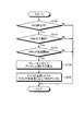
- FIG. 1 is a flowchart showing the operation of the first embodiment.
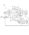
- FIG. 2 is a diagram illustrating a schematic configuration of the vehicle according to the first embodiment.
- FIG. 3 is a diagram showing a pedal arrangement of the hybrid vehicle.
- FIG. 4 is a diagram illustrating an example of a shift interface (shift pattern) of the shift lever according to the first embodiment.
- FIG. 5 is a time chart according to the vehicle control of the first embodiment.
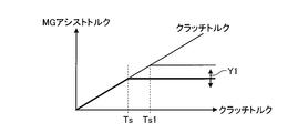
- FIG. 6 is an explanatory diagram of the assist upper limit torque.
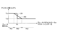
- FIG. 7 is a diagram showing the relationship between the brake operation amount and the assist upper limit torque.
- FIG. 8 is a diagram illustrating an example of a shift pattern of a vehicle equipped with a free-run system.
- FIG. 1 is a flowchart showing the operation of the first embodiment.
- FIG. 2 is a diagram illustrating a schematic configuration of the vehicle according to the first embodiment.
- FIG. 3 is a diagram showing a pedal arrangement of the hybrid vehicle.
- FIG. 4 is
- FIG. 9 is a diagram illustrating a schematic configuration of a vehicle according to the second embodiment.
- FIG. 10 is a flowchart showing the operation of the second embodiment.
- FIG. 11 is an explanatory diagram of vehicle control when the clutch torque can be estimated.
- FIG. 12 is an explanatory diagram of vehicle control when the clutch torque cannot be estimated.
- FIG. 13 is a time chart relating to vehicle control when the second target torque is larger than the regenerative maximum torque.
- FIG. 14 is another time chart relating to vehicle control when the second target torque is larger than the regenerative maximum torque.
- FIG. 15 is a time chart according to vehicle control when the second target torque is smaller than the regenerative maximum torque.
- FIG. 1 is a flowchart showing the operation of the first embodiment
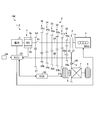
- FIG. 2 is a diagram showing a schematic configuration of the vehicle according to the first embodiment.
- the vehicle control device 1-1 of the present embodiment controls a vehicle in which a motor (see reference numeral 4 in FIG. 2) is closer to the driving wheel than a clutch (see reference numeral 2 in FIG. 2) and a three-pedal system is mounted. To do.
- the vehicle control device 1-1 stops the engine (see reference numeral 1 in FIG. 2) and starts the engine 1 at the timing when the driver selects the engine travel gear and engages the clutch 2 while traveling. At this time, the generation of a feeling of deceleration is suppressed by the motor assist up to the clutch engagement degree at which the clutch torque capable of cranking is generated. As a result, the driver is prevented from stopping the return operation of the clutch pedal before the start of cranking due to the occurrence of a feeling of deceleration, and the engine can be started reliably.
- the driver intends to decelerate.
- the driver intends to decelerate.
- motor assist is executed as in the case where the braking operation is not performed, power is wasted.
- the vehicle control device 1-1 of the present embodiment reduces the torque for canceling the deceleration feeling when the brake is depressed. Thereby, the assist amount of the motor 4 can be reduced to save power.
- This embodiment is based on a vehicle equipped with the following system.
- a 3-pedal system (2) A system in which MG is located on the vehicle side (drive wheel side) with respect to the clutch (the position of MG can be the T / M input shaft or the output shaft). (3) A system that can stop the engine while driving.
- the hybrid vehicle 100 includes an engine 1, a clutch 2, a manual transmission 3, a motor 4, and an ECU 30.
- the vehicle control device 1-1 according to the present embodiment includes an engine 1, a motor 4, a clutch 2, and an ECU 30.
- the engine 1 can function as a power source for the hybrid vehicle 100.
- the engine 1 converts the combustion energy of the fuel into a rotational motion of the output shaft 1a and outputs it.
- the output shaft 1a is connected to the input shaft 3A of the manual transmission 3 via the clutch 2.
- the clutch 2 is disposed in a power transmission path between the engine 1 and the input shaft 3A of the manual transmission 3, and connects or blocks transmission of power between the engine 1 and the input shaft 3A according to a driver's input.
- the clutch 2 is, for example, a friction engagement type clutch device, and includes an input side engagement member 21 and an output side engagement member 22.
- the input side engaging member 21 is connected to the output shaft 1 a of the engine 1, and the output side engaging member 22 is connected to the input shaft 3 A of the manual transmission 3.
- the clutch 2 connects the transmission of power between the engine 1 and the input shaft 3 ⁇ / b> A when the input side engagement member 21 and the output side engagement member 22 are engaged, and the input side engagement member 21 and the output side engagement are connected.
- the member 22 is open (separated), the transmission of power between the engine 1 and the input shaft 3A is cut off.
- the clutch 2 is engaged or released by a driver's operation input to the clutch pedal, and cannot be freely operated on the vehicle side.
- FIG. 3 is a diagram showing the pedal arrangement of the hybrid vehicle 100.
- the hybrid vehicle 100 includes three pedals: a clutch pedal 41, a brake pedal 42, and an accelerator pedal 43.
- the clutch 2 is released when the clutch pedal 41 is depressed, and the clutch 2 is engaged when the clutch pedal 41 is released.
- the clutch pedal 41 is provided with a clutch pedal stroke sensor 44 that detects the pedal stroke of the clutch pedal 41.
- the motor (MG) 4 has a stator 4a and a rotor 4b.
- the rotor 4b is connected to the rotation shaft 4c and rotates integrally with the rotation shaft 4c with the rotation shaft 4c as a rotation center.
- An MG gear 4d that rotates integrally with the rotation shaft 4c is disposed on the rotation shaft 4c.
- the motor 4 is connected to the battery 5 and is an electric motor that consumes electric power supplied from the battery 5 and outputs power to the rotating shaft 4c.
- the motor 4 can also function as a generator that converts the power transmitted through the rotating shaft 4c into electric power and outputs it.
- the manual transmission 3 is a manual transmission type transmission that is changed by a driver's operation input to the shift lever.
- the manual transmission 3 has an input shaft 3A, an output shaft 3B, and a synchronization device (not shown).
- the manual transmission 3 is a constant-mesh transmission, and has a plurality of forward gear pairs 31, 32, 33, 34, 35 and a reverse gear pair 36 that are always meshed.
- the synchronization device has a synchronization mechanism that synchronizes the rotation of the input shaft 3A and the rotation of the output shaft 3B in conjunction with a shift operation on the shift lever.
- Each forward gear pair 31, 32, 33, 34, 35 forms a gear stage having a different gear ratio.
- the first gear pair 31 is disposed on the input shaft 3A and is rotatable relative to the input shaft 3A.
- the first gear pair 31 is disposed on the output shaft 3B and is not relative to the output shaft 3B. 31b.
- the second gear pair 32, the third gear pair 33, the fourth gear pair 34, the fifth gear pair 35, and the reverse gear pair 36 are input gears 32a, 33a, 34a, 35a, 36a and outputs similar to the input gear 31a, respectively.
- Output gears 32b, 33b, 34b, 35b, and 36b similar to the gear 31b are provided.
- an input gear 36a and an output gear 36b are connected via an intermediate gear 36c.
- An output gear 37 is disposed on the output shaft 3B.
- the output gear 37 is connected to the output shaft 3B so as not to rotate relative to the output shaft 3B.
- the output gear 37 is in mesh with the MG gear 4 d of the motor 4. That is, the motor 4 is disposed closer to the drive wheel 8 than the engine 1 and the clutch 2.
- the synchronization device selectively engages any one of the gear pairs 31, 32, 33, 34, 35, and 36 to synchronize the rotation of the input shaft 3A and the rotation of the output shaft 3B.
- the transmission of power between the input shaft 3A and the output shaft 3B by the pair is connected.
- the synchronizer operates in conjunction with an operation input to the shift lever and engages with a gear pair corresponding to the range selected by the shift lever.
- the synchronization device disconnects all the gear pairs from the input shaft 3A and sets the manual transmission 3 to the neutral state.
- a pinion gear 38 is connected to the output shaft 3B of the manual transmission 3.
- the pinion gear 38 meshes with the diff ring gear 6.
- the differential ring gear 6 is connected to the left and right drive wheels 8 via a differential mechanism 7.
- the power of the engine 1 and the motor 4 output to the output shaft 3B is transmitted to the drive wheels 8 via the pinion gear 38, the diff ring gear 6 and the differential mechanism 7.
- the ECU 30 is an electronic control unit having a computer, and has a function as a travel control device of the hybrid vehicle 100.
- the ECU 30 is connected to the engine 1, the clutch 2, the manual transmission 3, and the motor 4.
- the ECU 30 can execute fuel injection control, ignition control, start control, and the like of the engine 1.
- a clutch pedal stroke sensor 44 is connected to the ECU 30.
- the ECU 30 can detect the degree of engagement of the clutch 2 based on a signal input from the clutch pedal stroke sensor 44.
- the ECU 30 may acquire the degree of engagement of the clutch 2 based on the detection result of the clutch stroke sensor that detects the stroke of the clutch 2 instead of the detection result of the clutch pedal stroke sensor 44.
- the ECU 30 can control the motor 4 and cause the motor 4 to output power.
- the power output by the motor 4 is transmitted to the drive wheels 8 via the output shaft 3B and the differential mechanism 7, and becomes a driving force that causes the hybrid vehicle 100 to travel.
- the ECU 30 can also cause the motor 4 to generate power.
- the ECU 30 can control the magnitude of power output from the motor 4 and the amount of power generated by the motor 4.
- the torque acting on the drive wheels 8 the torque for driving the hybrid vehicle 100 forward is referred to as positive torque
- the torque for driving the hybrid vehicle 100 rearward is described as negative torque or braking torque.
- the ECU 30 can cause the motor 4 to output either positive torque or negative torque.
- the ECU 30 can control the braking torque due to the power generation load of the motor 4 by adjusting the power generation amount of the motor 4.
- the output torque of the motor 4 is also referred to as “MG torque”.
- the ECU 30 receives signals indicating detection results of the shift position sensor and the neutral switch of the manual transmission 3.
- the shift position sensor detects a range selected in the manual transmission 3.
- the neutral switch detects that the manual transmission 3 is in a neutral state, in other words, that the transmission of power between the input shaft 3A and the output shaft 3B is interrupted.
- the ECU 30 is connected to the battery 5 and can control charging / discharging of the battery 5. Moreover, ECU30 is connected with the sensor which detects the voltage of the battery 5, the electric current which charges / discharges, etc., and can acquire charge amount SOC of the battery 5 based on the detection result of this sensor.
- the ECU 30 calculates the required torque or the required driving force to be transmitted to the drive wheels 8 based on conditions such as the vehicle speed and the accelerator opening, and controls the engine 1 and the motor 4 based on the calculation results.
- the ECU 30 can execute hybrid traveling in which the hybrid vehicle 100 travels using the power output from the engine 1 and the motor 4 and EV traveling in which the hybrid vehicle 100 travels using the power of the motor 4 regardless of the power of the engine 1.
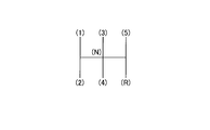
- FIG. 4 is a diagram showing an example of a shift interface (shift pattern) of the shift lever.
- the shift lever of the manual transmission 3 is provided with an R (reverse) range, an N (neutral) range, and an EV range in addition to five ranges (shift positions) corresponding to the first to fifth gears. It has been.
- the EV range is a range that instructs to perform EV traveling. When the shift position is operated in five ranges from the first speed to the fifth speed, the power of the engine 1 is transmitted from the input shaft 3A to the output shaft 3B through the gear pair corresponding to the shift position.
- the ECU30 makes the hybrid vehicle 100 drive
- the ECU 30 causes the hybrid vehicle 100 to travel with the power of the engine 1.
- the ECU 30 can cause the motor 4 to output positive torque to assist the engine 1, and can drive the motor 4 by the power of the engine 1 to cause the motor 4 to generate power. Further, the ECU 30 can cause the motor 4 to perform regenerative power generation when the hybrid vehicle 100 is decelerated or the like.
- the manual transmission 3 is in a neutral state in conjunction with the operation of the shift lever to the EV range. Thereby, while the EV range is selected, the transmission of power between the engine 1 and the output shaft 3B is cut off.
- ECU 30 stops engine 1 and executes EV travel. The ECU 30 controls the output torque of the motor 4 so as to realize the required torque.
- the ECU 30 restarts the engine 1 when the shift from the first forward speed to the fifth speed is performed by the driver's operation input during EV traveling and the clutch 2 is engaged.
- the ECU 30 starts the engine 1 when the clutch 2 is engaged and the engine 1 and the drive wheel 8 are connected while the engine 1 is stopped and traveling.
- the ECU 30 starts the engine by increasing the engine speed Ne by the cranking torque generated when the clutch 2 is engaged. That is, the ECU 30 starts the engine 1 with the power transmitted to the engine 1 via the clutch 2.
- the torque transmitted to the engine 1 via the clutch 2 includes torque transmitted from the drive wheels 8 via the manual transmission 3 and torque transmitted from the motor 4 via the manual transmission 3.
- cranking start torque is a lower limit of the clutch torque that enables cranking of the engine 1. Even if the clutch 2 is engaged, if the clutch torque of the clutch 2 is less than the cranking start torque, the engine 1 remains stopped.
- the clutch torque corresponds to the degree of engagement of the clutch 2 and can be the maximum torque that can be transmitted in the clutch 2.
- the vehicle acceleration (vehicle G) of the hybrid vehicle 100 decreases and a feeling of deceleration occurs. Due to this feeling of deceleration, there is a possibility that the driver stops the release of the clutch pedal 41 in expectation of an increase in the engine speed Ne and maintains the clutch stroke. This is related to the fact that, for example, the cranking start torque required to start increasing the rotation of the stopped engine 1 is larger than the torque required to increase the rotational speed of the engine 1 that is already rotating. . When a certain degree of deceleration occurs, the driver expects the clutch 2 to be fully engaged and the engine speed Ne to increase, but the clutch torque has reached a magnitude that allows the engine 1 to start rotating. A situation can occur that does not exist.
- the engine 1 If the engine 1 is still stopped despite expecting an increase in the engine speed Ne, the driver may feel uncomfortable and the drivability may be reduced. It is desirable that the engine 1 can be started more reliably when the clutch 2 is engaged.
- the vehicle control device 1-1 of the present embodiment suppresses a decrease in acceleration of the hybrid vehicle 100 due to the engagement of the clutch 2.
- the assist torque is output by the motor 4. Even if the clutch 2 starts to be engaged, the occurrence of a feeling of deceleration is suppressed, so that the driver is prevented from stopping the release of the clutch pedal 41 before the clutch torque reaches the cranking start torque. Thereby, it can be expected that the driver will surely release the clutch pedal 41 until the clutch stroke at which cranking starts, and the engine 1 can be started more reliably.
- the assist torque when the braking operation is performed is smaller than the assist torque when the braking operation is not performed.
- the assist torque when the braking operation is performed is a torque on the side where the acceleration of the hybrid vehicle 100 is reduced compared to the assist torque when the braking operation is not performed.
- FIG. 5 is a time chart according to the vehicle control of the present embodiment.
- FIG. 5 shows vehicle control in the case where the braking operation is performed with a constant brake operation amount before the clutch 2 is engaged.
- 5 (a) is the clutch stroke of the clutch pedal 41, (b) is the clutch torque, (c) is the rotation speed of the input shaft 3A of the manual transmission 3, (d) is the engine rotation speed Ne, (e).
- (f) represents MG torque.
- Reference numerals 101 and 103 denote vehicle acceleration and MG torque (hereinafter referred to as “vehicle acceleration during non-braking” and “MG torque during non-braking”) when the braking operation is not performed, respectively.
- Reference numerals 102 and 104 indicate vehicle acceleration and MG torque (hereinafter referred to as “vehicle acceleration during braking” and “MG torque during braking”) when the braking operation is performed, respectively.
- vehicle acceleration during braking vehicle acceleration during braking
- MG torque during braking vehicle acceleration during braking
- FIG. 5 it is assumed that the motor 4 does not output any torque other than the assist torque during braking and during non-braking.
- the vehicle control device 1-1 causes the motor 4 to output an assist torque in accordance with the clutch torque when the gear position for hybrid traveling is selected and the clutch 2 is engaged during EV traveling.
- the clutch torque has a range in which the assist torque is increased.
- the assist upper limit torque that is the upper limit of the range is based on the cranking start torque. When the clutch torque reaches a predetermined assist upper limit torque, the assist torque of the motor 4 is not further increased.
- the assist upper limit torque differs depending on whether or not a braking operation is performed.
- the assist upper limit torque Ts during braking is smaller than the assist upper limit torque Ts1 during non-braking. In other words, at the time of braking, the increase of the assist torque is finished when the clutch torque is smaller than that at the time of non-braking. As described below, even if the assist torque is reduced more than during non-braking during braking, it is considered that the driver does not feel uncomfortable and does not lead to a decrease in engine startability.
- the driver who has felt a sense of deceleration may stop the clutch operation assuming that the clutch 2 is engaged. In this case, the time until the engine is started may become longer, and the transition to acceleration may be delayed. However, since the driver is performing a braking operation and expects a deceleration, it is considered that even if the time until the engine start is slightly increased, the drivability is unlikely to decrease.
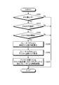
- control flow shown in FIG. 1 is executed while the hybrid vehicle 100 is traveling, and is repeatedly executed at predetermined intervals, for example.
- step S100 the ECU 30 determines whether or not the engine 1 is stopped.
- the EV is running
- an affirmative determination is made in step S100.
- step S100-Y if it is determined that the engine is stopped (step S100-Y), the process proceeds to step S110. If not (step S100-N), the control flow ends.
- step S110 the ECU 30 determines whether or not the ENG gear is selected.
- the ENG gear is a gear stage that travels while the engine 1 is operating. For example, if the selected gear stage is a gear stage for hybrid travel from the first speed to the fifth speed, an affirmative determination is made in step S110. As a result of the determination in step S110, if it is determined that the ENG gear is selected (step S110-Y), the process proceeds to step S120. If not (step S110-N), the control flow ends.
- step S120 the ECU 30 determines whether or not the clutch 2 has started to be engaged.
- the ECU 30 can make the determination in step S120 based on the detection result of the clutch pedal stroke sensor 44.
- the ECU 30 stores in advance a clutch stroke value (meet point) at which the clutch 2 starts to be engaged, and performs the determination in step S120 based on the comparison result between the pedal stroke at the meet point and the detected pedal stroke. be able to.
- step S120-Y if it is determined that the clutch 2 has started engagement (step S120-Y), the process proceeds to step S130, and if not (step S120-N), the control flow ends.
- step S130 the assist upper limit torque is calculated by the ECU 30.
- the ECU 30 calculates the assist upper limit torque according to the brake operation amount. For example, the ECU 30 calculates the assist upper limit torque based on the pedal stroke of the brake pedal 42 or the master cylinder pressure of the brake device.
- the assist upper limit torque Ts1 during non-braking is, for example, cranking start torque.
- the assist upper limit torque Ts1 during non-braking can be calculated, for example, by the following formula (1).
- Ts1 Maximum compression pressure + Maximum static friction (1)
- the ECU 30 can calculate the assist upper limit torque Ts1 during non-braking based on the maximum compression pressure of the engine 1 and the maximum static friction torque of the engine 1.
- the assist upper limit torque Ts1 during non-braking may be a torque that starts cranking within a certain time after the torque is applied to the engine 1.
- the air in the cylinder decreases as time elapses, and the compression pressure decreases. Therefore, the engine speed Ne does not increase all at once even when torque is applied, but there is torque that cranking starts due to a decrease in compression pressure. If the torque at which cranking starts within a certain standby time is set to the assist upper limit torque Ts1 during non-braking, the power consumption of the motor 4 can be suppressed.
- FIG. 6 is an explanatory diagram of the assist upper limit torque
- FIG. 7 is a diagram showing the relationship between the brake operation amount and the assist upper limit torque.
- the assist upper limit torque Ts during braking is smaller than the assist upper limit torque Ts1 during non-braking and is variable as indicated by an arrow Y1.
- the assist upper limit torque Ts during braking is variable according to the brake operation amount.
- the horizontal axis represents the brake operation amount, for example, the brake pedal stroke or the master cylinder pressure.
- Reference numeral 201 denotes an example of how to determine the assist upper limit torque Ts during braking based on the brake operation amount
- reference numeral 202 denotes another example of how to determine the assist upper limit torque Ts during braking based on the brake operation amount.
- the value when the brake operation amount is large is smaller than the value when the brake operation amount is small.
- the assist upper limit torque Ts at the time of braking may be set to a large or small value with a threshold Pt of the brake operation amount as a boundary.
- the assist upper limit torque Ts during braking is set to the same value as the assist upper limit torque Ts1 during non-braking when the brake operation amount is smaller than the threshold value Pt, and when the brake operation amount is greater than or equal to the threshold value Pt. You may make it become the value Ts2 smaller than assist upper limit torque Ts1.
- hysteresis may be provided in the vicinity of the threshold value Pt.
- the assist upper limit torque Ts during braking is gradually changed according to the change of the brake operation amount in the vicinity of the threshold value Pt, as indicated by reference numeral 202, instead of being changed discontinuously at the threshold value Pt. It may be. That is, the assist upper limit torque Ts during braking may be gradually decreased in accordance with an increase in the brake operation amount.
- the assist upper limit torque Ts at the time of braking is gradually decreased linearly as the brake operation amount increases, and the brake operation amount is smaller than the intermediate region Pb2.
- the assist upper limit torque Ts during braking may be set to a constant value.
- step S130 When the assist upper limit torque corresponding to the brake operation amount is calculated in step S130, the process proceeds to step S140.
- step S140 the ECU 30 performs MG assist according to the assist upper limit torque and the degree of clutch engagement.
- the ECU 30 controls the assist torque to be output to the motor 4 based on the assist upper limit torque calculated in step S130 and the clutch engagement degree detected by the clutch pedal stroke sensor 44.
- the ECU 30 stores the correspondence between the clutch stroke detected by the clutch pedal stroke sensor 44 and the degree of clutch engagement.
- the clutch engagement degree is the degree of engagement between the input side engagement member 21 and the output side engagement member 22 of the clutch 2 and corresponds to the clutch torque of the clutch 2.
- the ECU 30 sets the assist torque when the degree of engagement of the clutch 2 is large to a torque larger than the assist torque when the degree of engagement of the clutch 2 is small, with the assist upper limit torque calculated in step S130 as an upper limit.
- the assist torques 103 and 104 by the motor 4 increase according to the increase of the clutch torque.
- the ECU 30 increases the MG torque 103 in accordance with the increase in clutch torque when the MG torque 103 is less than the upper limit 103a corresponding to the assist upper limit torque Ts1 during non-braking. Thereby, the fall of the vehicle acceleration 101 of the hybrid vehicle 100 by the clutch 2 engaging is suppressed.
- the assist upper limit torque Ts1 during non-braking is the same torque as the cranking start torque.
- the ECU 30 makes the upper limit (predetermined torque) 104a of the assist torque during braking smaller than the upper limit (predetermined torque) 103a of the assist torque during non-braking.
- the ECU 30 increases the assist torque 103 according to the increase of the clutch torque with the upper limit 103a of the assist torque at the time of non-braking as the upper limit at the time of non-braking.
- the ECU 30 increases the assist torque 104 according to the increase of the clutch torque, with the upper limit 104a of the assist torque at the time of braking as the upper limit at the time of braking.
- the upper limit 103a of the assist torque at the time of non-braking corresponds to the assist upper limit torque Ts1 at the time of non-braking, and the vehicle acceleration due to the engagement of the clutch 2 with the degree of engagement that becomes the assist upper limit torque Ts1 at the time of non-braking. It is intended to suppress the decrease.
- the upper limit 104a of the assist torque at the time of braking corresponds to the assist upper limit torque Ts at the time of braking, and is due to the engagement of the clutch 2 with the degree of engagement that becomes the assist upper limit torque Ts at the time of braking. This suppresses a decrease in vehicle acceleration. Power consumption can be reduced by lowering the upper limit 104a of the assist torque during braking.
- the vehicle acceleration 102 starts to decrease at time t2 earlier than during non-braking. As a result, the driver's intention to decelerate that appears in engaging the clutch 2 can be realized early.
- the assist torque of the motor 4 may be adjusted based on the vehicle acceleration 102. For example, if the MG torque is feedback-controlled so as to realize the target deceleration based on the brake operation amount, a decrease in the vehicle acceleration 102 due to the engagement of the clutch 2 can be suppressed. At this time, if the assist upper limit torque Ts at the time of braking is the upper limit torque of the MG torque, it becomes possible to reduce power consumption at the time of braking or to realize the driver's intention to decelerate early. When MG assist is executed in step S140, this control flow ends.
- the assist upper limit torque Ts during braking is set to the assist upper limit torque during non-braking.
- Ts1 it is not limited to this.
- the rate of increase in assist torque may be made smaller for the same increase in clutch torque than during non-braking during braking.
- the rising of the MG torque 104 during braking may be made gentler than the rising of the MG torque 103 during non-braking.
- the assist upper limit torque Ts at the time of braking changes according to the amount of brake operation, but the assist upper limit torque Ts at the time of braking may be changed according to other parameters. For example, depending on the state of charge SOC of the battery 5, even if the assist upper limit torque Ts during braking when the state of charge SOC is low is smaller than the assist upper limit torque Ts during braking when the state of charge SOC is high. Good. Further, the assist upper limit torque Ts at the time of braking may be made variable according to environmental parameters such as a gradient.
- the control for providing a difference depending on the presence or absence of the braking operation to the upper limit of the assist torque at the time of clutch engagement is performed during EV traveling, but is not limited to this. Not only during EV travel, but when the engine 1 is stopped and the clutch 2 is engaged during travel to connect the engine 1 and the drive wheel 8, the upper limit of the assist torque is set to be different depending on the presence or absence of a braking operation. It may be.
- the upper limit of the assist torque when the forward gear is selected and the clutch 2 is engaged It is possible to provide a difference depending on the presence or absence of a braking operation.
- FIG. 8 is a diagram illustrating an example of a shift pattern when the hybrid vehicle 100 is equipped with a free-run system. Unlike the shift pattern of the first embodiment (FIG. 4), the EV range is not provided.
- the ECU 30 stops the engine 1 when the N range is selected during traveling. As an example, the ECU 30 stops the engine 1 when the clutch 2 is engaged while the N range is selected. Since the manual transmission 3 is in a neutral state, the drive wheel 8 is in a free-run state in which engine brake does not act, and the hybrid vehicle 100 travels by inertia. In this free run, the engine 1 can be stopped to improve fuel efficiency.
- the ECU 30 stops the engine 1 in a free run and selects the range for forward travel from the 1st speed to the 5th speed during traveling and the clutch 2 is engaged, in other words, the clutch 2 is engaged.
- the engine 1 and the drive wheel 8 are connected, the engine 1 is started with the power transmitted to the engine 1 via the clutch 2.
- the assist torque during braking is made smaller than the assist torque during non-braking.
- FIG. 9 is a diagram illustrating a schematic configuration of the vehicle according to the present embodiment
- FIG. 10 is a flowchart illustrating the operation of the present embodiment.
- the vehicle control device 1-2 of the present embodiment is different from the vehicle control device 1-1 of the first embodiment described above in that the ECB 50 is provided and a braking operation is performed when the clutch is engaged for engine restart.
- the target deceleration force determined by the braking operation is distributed to the MG torque, the deceleration force due to the engagement of the clutch 2, and the deceleration force due to the brake. Thereby, increase of regeneration amount and power saving can be aimed at.
- the vehicle control device 1-2 of the present embodiment includes a brake 9 and an ECB 50 in addition to the components of the vehicle control device 1-1 of the first embodiment.
- the brake 9 is a braking device that can control the braking force.
- the brake 9 is, for example, a hydraulic brake capable of controlling a braking force with supplied hydraulic pressure.
- the ECB 50 can control the braking force generated by the brake 9 of each wheel to a braking force different from the braking force corresponding to the amount of brake operation by the driver.
- the ECB 50 can control the braking force of each wheel to a desired value by controlling the hydraulic pressure supplied to the brake 9.
- the ECU 30 is connected to the ECB 50 and controls the deceleration force generated in the hybrid vehicle 100 in cooperation with the ECB 50.
- the vehicle control of this embodiment will be described with reference to FIG.
- the control flow shown in FIG. 10 is executed when the hybrid vehicle 100 is traveling, and is repeatedly executed at predetermined intervals, for example.
- Step S200 to step S220 can be the same as step S100 to step S120 of the first embodiment (FIG. 1). That is, when the engine 1 is stopped (step S200-Y), the ENG gear is selected (step S210-Y), and the clutch 2 starts to be engaged (step S220-Y), the ECU 30 Proceed to step S230.
- step S230 the ECU 30 calculates the deceleration force Tb.
- the deceleration force Tb takes a negative value.
- the ECU 30 calculates the deceleration force Tb based on the brake operation amount with respect to the brake pedal 42.
- the deceleration force Tb is a target deceleration force determined by the driver's braking operation.
- step S240 the assist upper limit torque is calculated by the ECU 30.
- the ECU 30 calculates the assist upper limit torque based on the brake operation amount with respect to the brake pedal 42. For example, the ECU 30 may calculate the assist upper limit torque in the same manner as in step S130 of the first embodiment.
- step S240 is executed, the process proceeds to step S250.
- step S250 the ECU 30 performs braking by the MG assist and the hydraulic brake according to the assist upper limit torque and the clutch engagement degree.
- the ECU 30 performs braking control as described below according to the assist upper limit torque calculated in step S240 and the degree of engagement of the clutch 2.
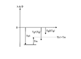
- FIG. 11 is an explanatory diagram of vehicle control when the clutch torque can be estimated.
- the symbol Tb1 indicates the target braking torque corresponding to the deceleration force Tb calculated in step S230
- the symbol Tm indicates the assist torque during braking according to the clutch torque.
- the sum (Tb1 + Tm) of the target braking torque Tb1 and the assist torque Tm during braking corresponding to the clutch torque is described as a target value of torque generated by the motor 4 and the brake 9 (hereinafter simply referred to as “first target torque”). .)
- the symbol Tg indicates the maximum regenerative torque of the motor 4.
- the maximum regeneration torque Tg is a negative torque having a maximum magnitude that can be output to the rotating shaft 4c when the motor 4 performs regenerative power generation.
- the ECU 30 causes the ECU 4 to Realize one target torque.
- the ECU 30 sets the output torque of the motor 4 as the first target torque. At this time, the braking torque by the brake is set to zero.
- the ECU 30 4 and the brake 9 are coordinated to achieve the first target torque.
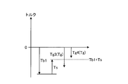
- the ECU 30 sets the regeneration amount of the motor 4 to the maximum, causes the motor 4 to generate power, and sets the braking torque by the brake 9 to a value that is insufficient due to regeneration of the motor 4, that is, a value represented by the following formula (2).
- Braking torque by brake Tb1 + Tm-Tg (2)
- FIG. 12 is an explanatory diagram of vehicle control when the clutch torque cannot be estimated.
- torque control may be performed so that the actual deceleration force becomes the target deceleration force.
- the ECU 30 sets the MG regeneration torque for realizing the deceleration force determined by the brake operation amount when the clutch 2 is not engaged and the braking torque by the brake 9 as the initial values of the MG torque and the brake braking torque.
- the ECU 30 realizes a target deceleration force by cooperative control of the motor 4 and the brake 9.
- the MG torque and the braking torque of the brake 9 are controlled so as to realize a target deceleration force based on the driver's braking operation.
- the braking force by the brake 9 is first removed, and when the braking force by the brake 9 becomes 0, the MG torque is increased.
- the generation of braking torque can be prioritized.
- the ECU 30 controls, for example, braking torque and MG torque by the brake 9 as described below.
- the sum (Tb1 + Ts) of the target braking torque Tb1 and the assist upper limit torque Ts during braking shown in FIG. 12 is the maximum value of the target value of torque generated by the motor 4 and the brake 9 (hereinafter simply referred to as “second target torque Tx”). ").
- second target torque Tx the maximum value of the target value of torque generated by the motor 4 and the brake 9
- the target deceleration force can be generated by the braking torque of the motor 4 regardless of the braking force by the brake 9.
- the braking force by the brake 9 can be reduced to 0 and the target deceleration force can be realized by MG torque.
- the upper limit of the MG torque when changing the MG torque is the second target torque Tx.
- FIGS. 13 and 14 are time charts related to vehicle control when the second target torque Tx is larger than the regenerative maximum torque Tg, respectively.
- FIG. 13 is a time chart when the second target torque Tx is negative
- FIG. 14 is a time chart when the second target torque Tx is positive.
- reference numeral 111 denotes vehicle acceleration during non-braking
- reference numeral 113 denotes MG torque during non-braking
- reference numeral 112 denotes vehicle acceleration during braking
- reference numeral 114 denotes MG torque during braking
- reference numeral 121 denotes vehicle acceleration during non-braking
- reference numeral 123 denotes MG torque during non-braking
- reference numeral 122 denotes vehicle acceleration during braking
- reference numeral 124 denotes MG torque during braking.
- FIGS. 13 and 14 show a case where a deceleration force corresponding to the brake operation amount can be generated by the braking torque of the motor 4.
- the ECU 30 does not operate the brake 9 and regenerates the motor 4.
- the hybrid vehicle 100 is braked.
- the MG torque 114 is controlled based on the deceleration of the hybrid vehicle 100.
- the ECU 30 controls the MG torque 114 based on the longitudinal acceleration of the hybrid vehicle 100 detected by the acceleration sensor so that the actual acceleration becomes an acceleration corresponding to the brake operation amount.
- MG torque 114 reaches upper limit second target torque Tx at time t12. Even if the clutch torque subsequently increases and the vehicle acceleration 112 decreases, the MG torque 114 is maintained at the second target torque.
- the regenerative amount of the motor 4 is increased by making the MG torque 114 during braking smaller than the MG torque 113 during non-braking.
- Time t13 is the time when the clutch torque reaches the assist upper limit torque Ts1 during non-braking
- time t14 is the time when the start of the engine 1 is completed.
- the ECU 30 sets the MG torque to the regenerative maximum torque Tg and causes the brake 9 to generate an insufficient braking torque. Specifically, the ECU 30 adjusts the brake 9 by setting the upper limit value of the braking torque by the brake 9 as a value of the following equation (3), and sets the MG torque to the regenerative maximum torque Tg.
- Upper limit of braking torque by brake Tb1 + Ts-Tg (3)
- FIG. 15 shows a time chart relating to vehicle control when the second target torque Tx is smaller than the regenerative maximum torque Tg.
- FIG. 15 shows (g) braking torque by the brake 9.
- Reference numeral 131 is vehicle acceleration during non-braking
- reference numeral 133 is MG torque during non-braking
- reference numeral 132 is vehicle acceleration during braking
- reference numeral 134 is MG torque during braking
- reference numeral 135 is braking torque due to braking. Indicates.
- the braking operation by the driver is started.
- the ECU 30 uses the MG torque 134 as the regenerative maximum torque Tg, and further generates the braking torque 135 by the brake to realize the target braking torque Tb1 according to the brake operation amount.
- the ECU 30 When the clutch 2 starts to be engaged at time t31, the ECU 30 reduces the magnitude of the braking torque 135 by the brake (decreases the braking force) so as to realize the target braking torque Tb1. By reducing the magnitude of the braking torque 135 by the brake, the decrease in the acceleration 132 of the hybrid vehicle 100 due to the engagement of the clutch 2 is suppressed. That is, the ECU 30 outputs assist torque by the brake 9 as a braking device instead of the motor 4. Not only the total amount of assist torque but also at least a part of the assist torque may be output by the brake 9.
- the ECU 30 sets the upper limit of the braking torque 135 due to the brake to 0 and increases the braking torque 135. Further, the ECU 30 keeps the MG torque 134 during braking as the regenerative maximum torque Tg without generating the assist torque by the motor 4 even if the clutch torque further increases after the braking torque 135 by the brake becomes zero. To do. As a result, although the vehicle acceleration 132 decreases after the time t33, it is difficult for the driver to feel uncomfortable because the braking operation is being performed. According to this control, the MG torque 134 at the time of braking can be maintained at the maximum regeneration torque Tg. Therefore, the regeneration amount is higher than when the assist torque is generated by the motor 4 like the MG torque 133 at the time of non-braking. Can be increased. Further, the assist torque is generated by the braking torque 135 by the brake until the braking torque 135 by the brake becomes zero. Therefore, it is possible to prevent the vehicle acceleration 132 from starting to decrease before the cranking starts, and to ensure the startability of the engine 1.
Landscapes
- Engineering & Computer Science (AREA)
- Chemical & Material Sciences (AREA)
- Combustion & Propulsion (AREA)
- Transportation (AREA)
- Mechanical Engineering (AREA)
- Automation & Control Theory (AREA)
- Hybrid Electric Vehicles (AREA)
- Electric Propulsion And Braking For Vehicles (AREA)
- Arrangement Of Transmissions (AREA)
- Regulating Braking Force (AREA)
- Gear-Shifting Mechanisms (AREA)
- Arrangement And Mounting Of Devices That Control Transmission Of Motive Force (AREA)
Abstract
Description
図1から図7を参照して、第1実施形態について説明する。本実施形態は、車両制御装置に関する。図1は、第1実施形態の動作を示すフローチャート、図2は、第1実施形態に係る車両の概略構成を示す図である。
(1)3ペダルのシステム。
(2)クラッチよりも車両側(駆動輪側)にMGがあるシステム(MGの位置は、T/Mの入力軸でも出力軸でも可能)。
(3)走行中にエンジンを停止できるシステム。
Ts1 = 最大コンプレッション圧 + 最大静止摩擦…(1)
ECU30は、エンジン1の最大コンプレッション圧と、エンジン1の最大静止摩擦トルクとに基づいて、非制動時のアシスト上限トルクTs1を算出することができる。
図8を参照して、第1実施形態の変形例について説明する。上記第1実施形態では、クラッチ係合時のアシストトルクの上限に制動操作の有無による差を設ける制御は、EV走行中に実行されたが、これに限定されるものではない。EV走行中に限らず、エンジン1を停止して走行中にクラッチ2が係合してエンジン1と駆動輪8とを接続する場合に、アシストトルクの上限に制動操作の有無による差を設けるようにしてもよい。
図9から図15を参照して、第2実施形態について説明する。第2実施形態については、上記実施形態で説明したものと同様の機能を有する構成要素には同一の符号を付して重複する説明は省略する。図9は、本実施形態に係る車両の概略構成を示す図、図10は、本実施形態の動作を示すフローチャートである。本実施形態の車両制御装置1-2において、上記第1実施形態の車両制御装置1-1と異なる点は、ECB50を備え、エンジン再始動に係るクラッチ係合時に制動操作がなされている場合、その制動操作により決まる目標減速力をMGトルク、クラッチ2の係合による減速力およびブレーキによる減速力に分配する。これにより、回生量の増加や節電を図ることができる。
ブレーキによる制動トルク = Tb1+Tm-Tg…(2)
ブレーキによる制動トルクの上限 = Tb1+Ts-Tg…(3)
1 エンジン
2 クラッチ
3 手動変速機
4 モータ
8 駆動輪
30 ECU
100 ハイブリッド車両
103a 非制動時のアシストトルクの上限
104a 制動時のアシストトルクの上限
Ts 制動時のアシスト上限トルク
Ts1 非制動時のアシスト上限トルク
Claims (7)
- エンジンと、
車両における前記エンジンよりも駆動輪側に配置されたモータと、
前記エンジンと前記モータとの間に配置され、操作入力によって係合あるいは開放するクラッチと、
を備え、
前記エンジンを停止して走行中に前記クラッチが係合して前記エンジンと前記駆動輪とを接続した場合に、前記クラッチを介して前記エンジンに伝達される動力で前記エンジンを始動し、かつ前記クラッチが係合することによる前記車両の加速度の低下を抑制するアシストトルクを前記モータによって出力させ、
制動操作がなされているときの前記アシストトルクは、前記制動操作がなされていないときの前記アシストトルクよりも小さい
ことを特徴とする車両制御装置。 - 予め定められた所定トルクを上限として、前記クラッチが係合するときの前記クラッチの係合度合いの増加に応じて前記アシストトルクを増加させ、
前記制動操作がなされているときの前記所定トルクは、前記制動操作がなされていないときの前記所定トルクよりも小さい
請求項1に記載の車両制御装置。 - 更に、制動力を制御可能な制動装置を備え、
前記エンジンを停止して走行中に前記クラッチが係合して前記エンジンと前記駆動輪とを接続した場合に、前記制動操作に基づく目標減速力に基づいて前記モータおよび前記制動装置を協調制御する
請求項1または2に記載の車両制御装置。 - 前記アシストトルクの少なくとも一部を前記モータに代えて前記制動装置によって出力させる
請求項3に記載の車両制御装置。 - 前記モータの回生による減速力の発生を前記制動装置による減速力の発生よりも優先する
請求項3に記載の車両制御装置。 - 制動操作がなされていないときの前記所定トルクは、前記エンジンのクランキングが開始する前記クラッチの係合度合いに対応している
請求項2に記載の車両制御装置。 - 更に、前記クラッチと前記駆動輪との間に配置された手動変速機を備え、
前記エンジンの動力および前記モータの動力によって前記車両を走行させるハイブリッド走行、および前記手動変速機が中立状態であるときに前記エンジンの動力によらずに前記モータの動力によって前記車両を走行させるEV走行を実行可能であり、
前記EV走行中に前記手動変速機において前記ハイブリッド走行用の変速段が選択され、かつ前記クラッチが係合して前記ハイブリッド走行に移行する場合に、前記アシストトルクを前記モータに出力させる
請求項1または2に記載の車両制御装置。
Priority Applications (5)
| Application Number | Priority Date | Filing Date | Title |
|---|---|---|---|
| DE112011105109.3T DE112011105109T5 (de) | 2011-03-30 | 2011-03-30 | Fahrzeugsteuerungsvorrichtung |
| JP2012520601A JP5267738B2 (ja) | 2011-03-30 | 2011-03-30 | 車両制御装置 |
| PCT/JP2011/058135 WO2012131958A1 (ja) | 2011-03-30 | 2011-03-30 | 車両制御装置 |
| CN201180068756.4A CN103492250B (zh) | 2011-03-30 | 2011-03-30 | 车辆控制装置 |
| US14/001,961 US9090256B2 (en) | 2011-03-30 | 2011-03-30 | Vehicle control device |
Applications Claiming Priority (1)
| Application Number | Priority Date | Filing Date | Title |
|---|---|---|---|
| PCT/JP2011/058135 WO2012131958A1 (ja) | 2011-03-30 | 2011-03-30 | 車両制御装置 |
Publications (1)
| Publication Number | Publication Date |
|---|---|
| WO2012131958A1 true WO2012131958A1 (ja) | 2012-10-04 |
Family
ID=46929781
Family Applications (1)
| Application Number | Title | Priority Date | Filing Date |
|---|---|---|---|
| PCT/JP2011/058135 Ceased WO2012131958A1 (ja) | 2011-03-30 | 2011-03-30 | 車両制御装置 |
Country Status (5)
| Country | Link |
|---|---|
| US (1) | US9090256B2 (ja) |
| JP (1) | JP5267738B2 (ja) |
| CN (1) | CN103492250B (ja) |
| DE (1) | DE112011105109T5 (ja) |
| WO (1) | WO2012131958A1 (ja) |
Cited By (1)
| Publication number | Priority date | Publication date | Assignee | Title |
|---|---|---|---|---|
| CN103963765A (zh) * | 2013-01-29 | 2014-08-06 | 罗伯特·博世有限公司 | 制动需求检测的方法、针对车辆的制动系统的检测的装置及车辆制动系统的传感器 |
Families Citing this family (13)
| Publication number | Priority date | Publication date | Assignee | Title |
|---|---|---|---|---|
| JP5641610B2 (ja) * | 2011-03-11 | 2014-12-17 | アイシン・エーアイ株式会社 | 手動変速機 |
| KR101999876B1 (ko) * | 2012-02-03 | 2019-07-12 | 지이 하이브리드 테크놀로지스, 엘엘씨 | 하이브리드 차량에 동력을 전달하기 위한 장치 및 방법 |
| US11161403B2 (en) | 2012-02-03 | 2021-11-02 | Ge Hybrid Technologies, Llc | Apparatus and method for delivering power in a hybrid vehicle |
| JP2017114245A (ja) * | 2015-12-22 | 2017-06-29 | ローベルト ボッシュ ゲゼルシャフト ミット ベシュレンクテル ハフツング | 制御装置及び制御方法 |
| JP6515875B2 (ja) * | 2016-06-10 | 2019-05-22 | 株式会社デンソー | 車載電源システム |
| JP6888528B2 (ja) * | 2017-11-20 | 2021-06-16 | トヨタ自動車株式会社 | ハイブリッド車の制御装置 |
| US10857991B2 (en) * | 2018-03-08 | 2020-12-08 | Ford Global Technologies, Llc | Hybrid vehicle engine start/stop system |
| JP2020159326A (ja) * | 2019-03-27 | 2020-10-01 | いすゞ自動車株式会社 | 車速制御装置 |
| JP7388213B2 (ja) * | 2020-01-31 | 2023-11-29 | トヨタ自動車株式会社 | ハイブリッド車両の制御装置 |
| CN113997936B (zh) * | 2021-12-09 | 2024-04-05 | 蜂巢传动科技河北有限公司 | 一种混合动力车辆的控制方法、装置、存储介质及车辆 |
| US20240067156A1 (en) * | 2022-08-23 | 2024-02-29 | Ford Global Technologies, Llc | Method and system for controlling a modular hybrid transmission |
| KR102746037B1 (ko) * | 2022-12-15 | 2024-12-27 | 주식회사 현대케피코 | 마일드 하이브리드 차량의 비상 관성 클러치 시동 방법 및 시스템 |
| JP2025089736A (ja) * | 2023-12-04 | 2025-06-16 | トヨタ自動車株式会社 | 車両制御システム |
Citations (6)
| Publication number | Priority date | Publication date | Assignee | Title |
|---|---|---|---|---|
| JPH08182114A (ja) * | 1994-12-26 | 1996-07-12 | Toyota Motor Corp | 車両の内燃機関の加速補助装置 |
| JP2004140942A (ja) * | 2002-10-18 | 2004-05-13 | Toyota Motor Corp | 車両用駆動制御装置 |
| JP2006240608A (ja) * | 2005-02-04 | 2006-09-14 | Toyota Motor Corp | 車両用駆動装置の制御装置 |
| JP2009196474A (ja) * | 2008-02-20 | 2009-09-03 | Toyota Motor Corp | ハイブリッド車およびその制御方法並びに駆動装置 |
| JP2009227277A (ja) * | 2009-07-08 | 2009-10-08 | Nissan Motor Co Ltd | ハイブリッド車両の駆動力制御装置 |
| JP2011005904A (ja) * | 2009-06-24 | 2011-01-13 | Toyota Motor Corp | ハイブリッド車両の制御装置 |
Family Cites Families (9)
| Publication number | Priority date | Publication date | Assignee | Title |
|---|---|---|---|---|
| JP3861321B2 (ja) * | 1996-05-02 | 2006-12-20 | トヨタ自動車株式会社 | ハイブリッド車 |
| JP3214427B2 (ja) * | 1997-12-12 | 2001-10-02 | トヨタ自動車株式会社 | ハイブリッド車の駆動制御装置 |
| US7935021B2 (en) * | 2004-10-27 | 2011-05-03 | Toyota Jidosha Kabushiki Kaisha | Controller apparatus for vehicular device system |
| DE102006030102A1 (de) | 2005-06-29 | 2007-01-18 | Continental Teves Ag & Co. Ohg | Assistenzsystem |
| JP5176421B2 (ja) * | 2007-08-03 | 2013-04-03 | 日産自動車株式会社 | ハイブリッド車両の制御装置 |
| US8285432B2 (en) * | 2007-11-05 | 2012-10-09 | GM Global Technology Operations LLC | Method and apparatus for developing a control architecture for coordinating shift execution and engine torque control |
| US8141534B2 (en) * | 2010-02-03 | 2012-03-27 | Ford Global Technologies, Llc | Methods and systems for assisted direct start control |
| CN101941436B (zh) * | 2010-08-13 | 2013-10-30 | 芜湖伯特利汽车安全系统有限公司 | 一种应用于机动车的电子驻车制动系统及其辅助起步方法 |
| CN103442958B (zh) | 2011-03-30 | 2016-03-23 | 丰田自动车株式会社 | 车辆的控制系统 |
-
2011
- 2011-03-30 US US14/001,961 patent/US9090256B2/en not_active Expired - Fee Related
- 2011-03-30 JP JP2012520601A patent/JP5267738B2/ja active Active
- 2011-03-30 DE DE112011105109.3T patent/DE112011105109T5/de not_active Withdrawn
- 2011-03-30 WO PCT/JP2011/058135 patent/WO2012131958A1/ja not_active Ceased
- 2011-03-30 CN CN201180068756.4A patent/CN103492250B/zh not_active Expired - Fee Related
Patent Citations (6)
| Publication number | Priority date | Publication date | Assignee | Title |
|---|---|---|---|---|
| JPH08182114A (ja) * | 1994-12-26 | 1996-07-12 | Toyota Motor Corp | 車両の内燃機関の加速補助装置 |
| JP2004140942A (ja) * | 2002-10-18 | 2004-05-13 | Toyota Motor Corp | 車両用駆動制御装置 |
| JP2006240608A (ja) * | 2005-02-04 | 2006-09-14 | Toyota Motor Corp | 車両用駆動装置の制御装置 |
| JP2009196474A (ja) * | 2008-02-20 | 2009-09-03 | Toyota Motor Corp | ハイブリッド車およびその制御方法並びに駆動装置 |
| JP2011005904A (ja) * | 2009-06-24 | 2011-01-13 | Toyota Motor Corp | ハイブリッド車両の制御装置 |
| JP2009227277A (ja) * | 2009-07-08 | 2009-10-08 | Nissan Motor Co Ltd | ハイブリッド車両の駆動力制御装置 |
Cited By (1)
| Publication number | Priority date | Publication date | Assignee | Title |
|---|---|---|---|---|
| CN103963765A (zh) * | 2013-01-29 | 2014-08-06 | 罗伯特·博世有限公司 | 制动需求检测的方法、针对车辆的制动系统的检测的装置及车辆制动系统的传感器 |
Also Published As
| Publication number | Publication date |
|---|---|
| US20140011630A1 (en) | 2014-01-09 |
| CN103492250A (zh) | 2014-01-01 |
| US9090256B2 (en) | 2015-07-28 |
| DE112011105109T5 (de) | 2014-01-16 |
| JP5267738B2 (ja) | 2013-08-21 |
| JPWO2012131958A1 (ja) | 2014-07-24 |
| CN103492250B (zh) | 2016-09-14 |
Similar Documents
| Publication | Publication Date | Title |
|---|---|---|
| JP5267738B2 (ja) | 車両制御装置 | |
| JP5454698B2 (ja) | ハイブリッド車両の制御装置 | |
| JP5338300B2 (ja) | エンジン始動制御装置及びエンジン始動制御方法 | |
| JP5988653B2 (ja) | ハイブリッド電気自動車の制御装置 | |
| JP6241424B2 (ja) | 車両制御装置 | |
| JP2009035188A (ja) | ハイブリッド車両の制御装置 | |
| CN103842222B (zh) | 发动机起动系统 | |
| JP2010195363A (ja) | ハイブリッド車両の制御装置 | |
| JP5765419B2 (ja) | 車両および車両用制御方法 | |
| JP5462057B2 (ja) | 車両の動力伝達制御装置 | |
| JP2007168551A (ja) | ハイブリッド車両の制御装置 | |
| JP4178947B2 (ja) | 変速機の制御装置 | |
| JP5648739B2 (ja) | 車両の制御システム | |
| JP5218161B2 (ja) | ハイブリッド車両の制御装置 | |
| WO2021220694A1 (ja) | 車両用制動装置 | |
| JP7555172B2 (ja) | ハイブリッドシステム | |
| JP6777225B2 (ja) | ハイブリッド車両の制御方法及びハイブリッド車両の制御装置 | |
| JP2010184614A (ja) | 車両制御装置 | |
| JPWO2014136364A1 (ja) | 車両の変速制御装置 | |
| JP2012171521A (ja) | ハイブリッド車両の駆動制御装置 | |
| JP5691383B2 (ja) | 車両用走行制御装置 | |
| JP7056261B2 (ja) | 車両 | |
| JP2018065399A (ja) | ハイブリッド車両の制御装置及びハイブリッド車両 | |
| WO2015019789A1 (ja) | フライホイール回生システム及びその制御方法 | |
| JP2014177178A (ja) | ハイブリッド電気自動車の制御装置 |
Legal Events
| Date | Code | Title | Description |
|---|---|---|---|
| ENP | Entry into the national phase |
Ref document number: 2012520601 Country of ref document: JP Kind code of ref document: A |
|
| 121 | Ep: the epo has been informed by wipo that ep was designated in this application |
Ref document number: 11862303 Country of ref document: EP Kind code of ref document: A1 |
|
| WWE | Wipo information: entry into national phase |
Ref document number: 14001961 Country of ref document: US |
|
| WWE | Wipo information: entry into national phase |
Ref document number: 112011105109 Country of ref document: DE Ref document number: 1120111051093 Country of ref document: DE |
|
| 122 | Ep: pct application non-entry in european phase |
Ref document number: 11862303 Country of ref document: EP Kind code of ref document: A1 |