WO2012131800A1 - 電池パックおよび電動自転車 - Google Patents
電池パックおよび電動自転車 Download PDFInfo
- Publication number
- WO2012131800A1 WO2012131800A1 PCT/JP2011/005030 JP2011005030W WO2012131800A1 WO 2012131800 A1 WO2012131800 A1 WO 2012131800A1 JP 2011005030 W JP2011005030 W JP 2011005030W WO 2012131800 A1 WO2012131800 A1 WO 2012131800A1
- Authority
- WO
- WIPO (PCT)
- Prior art keywords
- battery
- battery pack
- plate
- tab
- unit
- Prior art date
Links
- 239000000758 substrate Substances 0.000 claims abstract description 47
- 239000000463 material Substances 0.000 claims abstract description 33
- 235000019589 hardness Nutrition 0.000 claims abstract description 8
- 230000009974 thixotropic effect Effects 0.000 claims abstract description 3
- 230000001681 protective effect Effects 0.000 claims description 7
- 238000007599 discharging Methods 0.000 claims description 5
- 230000004888 barrier function Effects 0.000 abstract 2
- 239000002699 waste material Substances 0.000 abstract 1
- 238000000605 extraction Methods 0.000 description 45
- 238000010586 diagram Methods 0.000 description 27
- 238000004519 manufacturing process Methods 0.000 description 25
- 239000010408 film Substances 0.000 description 17
- 239000010409 thin film Substances 0.000 description 17
- 238000000034 method Methods 0.000 description 16
- 238000003780 insertion Methods 0.000 description 15
- 230000037431 insertion Effects 0.000 description 15
- PXHVJJICTQNCMI-UHFFFAOYSA-N Nickel Chemical compound [Ni] PXHVJJICTQNCMI-UHFFFAOYSA-N 0.000 description 14
- 230000008569 process Effects 0.000 description 14
- 238000005192 partition Methods 0.000 description 11
- HBBGRARXTFLTSG-UHFFFAOYSA-N Lithium ion Chemical compound [Li+] HBBGRARXTFLTSG-UHFFFAOYSA-N 0.000 description 10
- 239000002390 adhesive tape Substances 0.000 description 10
- 229910052782 aluminium Inorganic materials 0.000 description 10
- XAGFODPZIPBFFR-UHFFFAOYSA-N aluminium Chemical compound [Al] XAGFODPZIPBFFR-UHFFFAOYSA-N 0.000 description 10
- 229910001416 lithium ion Inorganic materials 0.000 description 10
- 239000000853 adhesive Substances 0.000 description 8
- 230000001070 adhesive effect Effects 0.000 description 8
- 239000011248 coating agent Substances 0.000 description 7
- 238000000576 coating method Methods 0.000 description 7
- 229910052759 nickel Inorganic materials 0.000 description 7
- 239000005022 packaging material Substances 0.000 description 7
- 229920005989 resin Polymers 0.000 description 7
- 239000011347 resin Substances 0.000 description 7
- 229910052751 metal Inorganic materials 0.000 description 6
- 239000002184 metal Substances 0.000 description 6
- XLYOFNOQVPJJNP-UHFFFAOYSA-N water Substances O XLYOFNOQVPJJNP-UHFFFAOYSA-N 0.000 description 6
- -1 polyethylene terephthalate Polymers 0.000 description 5
- 125000006850 spacer group Chemical group 0.000 description 5
- 229910000838 Al alloy Inorganic materials 0.000 description 4
- 229920003002 synthetic resin Polymers 0.000 description 4
- 239000000057 synthetic resin Substances 0.000 description 4
- 229920000122 acrylonitrile butadiene styrene Polymers 0.000 description 3
- 230000009471 action Effects 0.000 description 3
- 239000004020 conductor Substances 0.000 description 3
- 239000011888 foil Substances 0.000 description 3
- 239000002245 particle Substances 0.000 description 3
- 230000002093 peripheral effect Effects 0.000 description 3
- 230000000704 physical effect Effects 0.000 description 3
- 229920000139 polyethylene terephthalate Polymers 0.000 description 3
- 239000005020 polyethylene terephthalate Substances 0.000 description 3
- 230000035939 shock Effects 0.000 description 3
- RYGMFSIKBFXOCR-UHFFFAOYSA-N Copper Chemical compound [Cu] RYGMFSIKBFXOCR-UHFFFAOYSA-N 0.000 description 2
- 230000004308 accommodation Effects 0.000 description 2
- 230000002411 adverse Effects 0.000 description 2
- 238000009833 condensation Methods 0.000 description 2
- 230000005494 condensation Effects 0.000 description 2
- 239000013256 coordination polymer Substances 0.000 description 2
- 229910052802 copper Inorganic materials 0.000 description 2
- 239000010949 copper Substances 0.000 description 2
- 230000006866 deterioration Effects 0.000 description 2
- 230000000694 effects Effects 0.000 description 2
- 239000008151 electrolyte solution Substances 0.000 description 2
- 230000017525 heat dissipation Effects 0.000 description 2
- 238000010030 laminating Methods 0.000 description 2
- 230000007246 mechanism Effects 0.000 description 2
- 229920005668 polycarbonate resin Polymers 0.000 description 2
- 239000004431 polycarbonate resin Substances 0.000 description 2
- 229920001296 polysiloxane Polymers 0.000 description 2
- 238000007789 sealing Methods 0.000 description 2
- 239000004593 Epoxy Substances 0.000 description 1
- 239000004677 Nylon Substances 0.000 description 1
- 239000004698 Polyethylene Substances 0.000 description 1
- 239000004743 Polypropylene Substances 0.000 description 1
- 229910052581 Si3N4 Inorganic materials 0.000 description 1
- 230000002159 abnormal effect Effects 0.000 description 1
- 239000006096 absorbing agent Substances 0.000 description 1
- PNEYBMLMFCGWSK-UHFFFAOYSA-N aluminium oxide Inorganic materials [O-2].[O-2].[O-2].[Al+3].[Al+3] PNEYBMLMFCGWSK-UHFFFAOYSA-N 0.000 description 1
- 239000012080 ambient air Substances 0.000 description 1
- 230000033228 biological regulation Effects 0.000 description 1
- 230000015572 biosynthetic process Effects 0.000 description 1
- 238000009529 body temperature measurement Methods 0.000 description 1
- 230000008859 change Effects 0.000 description 1
- 238000001816 cooling Methods 0.000 description 1
- YOCUPQPZWBBYIX-UHFFFAOYSA-N copper nickel Chemical compound [Ni].[Cu] YOCUPQPZWBBYIX-UHFFFAOYSA-N 0.000 description 1
- PMHQVHHXPFUNSP-UHFFFAOYSA-M copper(1+);methylsulfanylmethane;bromide Chemical compound Br[Cu].CSC PMHQVHHXPFUNSP-UHFFFAOYSA-M 0.000 description 1
- 230000004927 fusion Effects 0.000 description 1
- 239000011521 glass Substances 0.000 description 1
- 230000020169 heat generation Effects 0.000 description 1
- 230000006872 improvement Effects 0.000 description 1
- 238000009413 insulation Methods 0.000 description 1
- 238000005304 joining Methods 0.000 description 1
- 230000007774 longterm Effects 0.000 description 1
- 239000007769 metal material Substances 0.000 description 1
- 238000012544 monitoring process Methods 0.000 description 1
- 229920001778 nylon Polymers 0.000 description 1
- 230000000149 penetrating effect Effects 0.000 description 1
- 229920000573 polyethylene Polymers 0.000 description 1
- 229920001155 polypropylene Polymers 0.000 description 1
- 238000010079 rubber tapping Methods 0.000 description 1
- 239000011359 shock absorbing material Substances 0.000 description 1
- HQVNEWCFYHHQES-UHFFFAOYSA-N silicon nitride Chemical compound N12[Si]34N5[Si]62N3[Si]51N64 HQVNEWCFYHHQES-UHFFFAOYSA-N 0.000 description 1
- 239000013464 silicone adhesive Substances 0.000 description 1
- 229920002050 silicone resin Polymers 0.000 description 1
- 238000003860 storage Methods 0.000 description 1
- 238000004804 winding Methods 0.000 description 1
Images


Classifications
-
- H—ELECTRICITY
- H01—ELECTRIC ELEMENTS
- H01M—PROCESSES OR MEANS, e.g. BATTERIES, FOR THE DIRECT CONVERSION OF CHEMICAL ENERGY INTO ELECTRICAL ENERGY
- H01M10/00—Secondary cells; Manufacture thereof
- H01M10/42—Methods or arrangements for servicing or maintenance of secondary cells or secondary half-cells
- H01M10/425—Structural combination with electronic components, e.g. electronic circuits integrated to the outside of the casing
- H01M10/4257—Smart batteries, e.g. electronic circuits inside the housing of the cells or batteries
-
- H—ELECTRICITY
- H01—ELECTRIC ELEMENTS
- H01M—PROCESSES OR MEANS, e.g. BATTERIES, FOR THE DIRECT CONVERSION OF CHEMICAL ENERGY INTO ELECTRICAL ENERGY
- H01M10/00—Secondary cells; Manufacture thereof
- H01M10/05—Accumulators with non-aqueous electrolyte
- H01M10/052—Li-accumulators
- H01M10/0525—Rocking-chair batteries, i.e. batteries with lithium insertion or intercalation in both electrodes; Lithium-ion batteries
-
- H—ELECTRICITY
- H01—ELECTRIC ELEMENTS
- H01M—PROCESSES OR MEANS, e.g. BATTERIES, FOR THE DIRECT CONVERSION OF CHEMICAL ENERGY INTO ELECTRICAL ENERGY
- H01M10/00—Secondary cells; Manufacture thereof
- H01M10/05—Accumulators with non-aqueous electrolyte
- H01M10/058—Construction or manufacture
- H01M10/0585—Construction or manufacture of accumulators having only flat construction elements, i.e. flat positive electrodes, flat negative electrodes and flat separators
-
- H—ELECTRICITY
- H01—ELECTRIC ELEMENTS
- H01M—PROCESSES OR MEANS, e.g. BATTERIES, FOR THE DIRECT CONVERSION OF CHEMICAL ENERGY INTO ELECTRICAL ENERGY
- H01M50/00—Constructional details or processes of manufacture of the non-active parts of electrochemical cells other than fuel cells, e.g. hybrid cells
- H01M50/20—Mountings; Secondary casings or frames; Racks, modules or packs; Suspension devices; Shock absorbers; Transport or carrying devices; Holders
- H01M50/233—Mountings; Secondary casings or frames; Racks, modules or packs; Suspension devices; Shock absorbers; Transport or carrying devices; Holders characterised by physical properties of casings or racks, e.g. dimensions
- H01M50/24—Mountings; Secondary casings or frames; Racks, modules or packs; Suspension devices; Shock absorbers; Transport or carrying devices; Holders characterised by physical properties of casings or racks, e.g. dimensions adapted for protecting batteries from their environment, e.g. from corrosion
-
- H—ELECTRICITY
- H01—ELECTRIC ELEMENTS
- H01M—PROCESSES OR MEANS, e.g. BATTERIES, FOR THE DIRECT CONVERSION OF CHEMICAL ENERGY INTO ELECTRICAL ENERGY
- H01M2220/00—Batteries for particular applications
- H01M2220/20—Batteries in motive systems, e.g. vehicle, ship, plane
-
- H—ELECTRICITY
- H01—ELECTRIC ELEMENTS
- H01M—PROCESSES OR MEANS, e.g. BATTERIES, FOR THE DIRECT CONVERSION OF CHEMICAL ENERGY INTO ELECTRICAL ENERGY
- H01M50/00—Constructional details or processes of manufacture of the non-active parts of electrochemical cells other than fuel cells, e.g. hybrid cells
- H01M50/10—Primary casings; Jackets or wrappings
- H01M50/102—Primary casings; Jackets or wrappings characterised by their shape or physical structure
- H01M50/105—Pouches or flexible bags
-
- H—ELECTRICITY
- H01—ELECTRIC ELEMENTS
- H01M—PROCESSES OR MEANS, e.g. BATTERIES, FOR THE DIRECT CONVERSION OF CHEMICAL ENERGY INTO ELECTRICAL ENERGY
- H01M50/00—Constructional details or processes of manufacture of the non-active parts of electrochemical cells other than fuel cells, e.g. hybrid cells
- H01M50/20—Mountings; Secondary casings or frames; Racks, modules or packs; Suspension devices; Shock absorbers; Transport or carrying devices; Holders
- H01M50/204—Racks, modules or packs for multiple batteries or multiple cells
- H01M50/207—Racks, modules or packs for multiple batteries or multiple cells characterised by their shape
- H01M50/211—Racks, modules or packs for multiple batteries or multiple cells characterised by their shape adapted for pouch cells
-
- H—ELECTRICITY
- H01—ELECTRIC ELEMENTS
- H01M—PROCESSES OR MEANS, e.g. BATTERIES, FOR THE DIRECT CONVERSION OF CHEMICAL ENERGY INTO ELECTRICAL ENERGY
- H01M50/00—Constructional details or processes of manufacture of the non-active parts of electrochemical cells other than fuel cells, e.g. hybrid cells
- H01M50/50—Current conducting connections for cells or batteries
- H01M50/502—Interconnectors for connecting terminals of adjacent batteries; Interconnectors for connecting cells outside a battery casing
- H01M50/509—Interconnectors for connecting terminals of adjacent batteries; Interconnectors for connecting cells outside a battery casing characterised by the type of connection, e.g. mixed connections
- H01M50/51—Connection only in series
-
- H—ELECTRICITY
- H01—ELECTRIC ELEMENTS
- H01M—PROCESSES OR MEANS, e.g. BATTERIES, FOR THE DIRECT CONVERSION OF CHEMICAL ENERGY INTO ELECTRICAL ENERGY
- H01M50/00—Constructional details or processes of manufacture of the non-active parts of electrochemical cells other than fuel cells, e.g. hybrid cells
- H01M50/50—Current conducting connections for cells or batteries
- H01M50/502—Interconnectors for connecting terminals of adjacent batteries; Interconnectors for connecting cells outside a battery casing
- H01M50/509—Interconnectors for connecting terminals of adjacent batteries; Interconnectors for connecting cells outside a battery casing characterised by the type of connection, e.g. mixed connections
- H01M50/512—Connection only in parallel
-
- H—ELECTRICITY
- H01—ELECTRIC ELEMENTS
- H01M—PROCESSES OR MEANS, e.g. BATTERIES, FOR THE DIRECT CONVERSION OF CHEMICAL ENERGY INTO ELECTRICAL ENERGY
- H01M50/00—Constructional details or processes of manufacture of the non-active parts of electrochemical cells other than fuel cells, e.g. hybrid cells
- H01M50/50—Current conducting connections for cells or batteries
- H01M50/543—Terminals
- H01M50/547—Terminals characterised by the disposition of the terminals on the cells
- H01M50/55—Terminals characterised by the disposition of the terminals on the cells on the same side of the cell
-
- H—ELECTRICITY
- H01—ELECTRIC ELEMENTS
- H01M—PROCESSES OR MEANS, e.g. BATTERIES, FOR THE DIRECT CONVERSION OF CHEMICAL ENERGY INTO ELECTRICAL ENERGY
- H01M50/00—Constructional details or processes of manufacture of the non-active parts of electrochemical cells other than fuel cells, e.g. hybrid cells
- H01M50/50—Current conducting connections for cells or batteries
- H01M50/543—Terminals
- H01M50/552—Terminals characterised by their shape
- H01M50/553—Terminals adapted for prismatic, pouch or rectangular cells
- H01M50/557—Plate-shaped terminals
-
- Y—GENERAL TAGGING OF NEW TECHNOLOGICAL DEVELOPMENTS; GENERAL TAGGING OF CROSS-SECTIONAL TECHNOLOGIES SPANNING OVER SEVERAL SECTIONS OF THE IPC; TECHNICAL SUBJECTS COVERED BY FORMER USPC CROSS-REFERENCE ART COLLECTIONS [XRACs] AND DIGESTS
- Y02—TECHNOLOGIES OR APPLICATIONS FOR MITIGATION OR ADAPTATION AGAINST CLIMATE CHANGE
- Y02E—REDUCTION OF GREENHOUSE GAS [GHG] EMISSIONS, RELATED TO ENERGY GENERATION, TRANSMISSION OR DISTRIBUTION
- Y02E60/00—Enabling technologies; Technologies with a potential or indirect contribution to GHG emissions mitigation
- Y02E60/10—Energy storage using batteries
-
- Y—GENERAL TAGGING OF NEW TECHNOLOGICAL DEVELOPMENTS; GENERAL TAGGING OF CROSS-SECTIONAL TECHNOLOGIES SPANNING OVER SEVERAL SECTIONS OF THE IPC; TECHNICAL SUBJECTS COVERED BY FORMER USPC CROSS-REFERENCE ART COLLECTIONS [XRACs] AND DIGESTS
- Y02—TECHNOLOGIES OR APPLICATIONS FOR MITIGATION OR ADAPTATION AGAINST CLIMATE CHANGE
- Y02P—CLIMATE CHANGE MITIGATION TECHNOLOGIES IN THE PRODUCTION OR PROCESSING OF GOODS
- Y02P70/00—Climate change mitigation technologies in the production process for final industrial or consumer products
- Y02P70/50—Manufacturing or production processes characterised by the final manufactured product
Definitions
- the present invention relates to a battery pack configured by connecting a plurality of secondary batteries, and an electric bicycle equipped with the battery pack.
- Lithium ion secondary batteries in which charging and discharging are performed by moving lithium ions between the negative electrode and the positive electrode, Since it has battery characteristics of high energy density and high output, it is suitable as a battery for driving power supply.
- the lithium ion battery a cylindrical battery obtained by winding a positive electrode and a negative electrode laminated via a separator, and a flat battery obtained by laminating a positive electrode and a negative electrode via a separator are known.
- the flat ones can easily increase the capacity per unit cell by increasing the area of the positive electrode and negative electrode, or increasing the number of positive and negative electrodes to be stacked.
- Patent Document 1 Japanese Patent Laid-Open No. 2007-257901 proposes a battery pack for an electric bicycle using a film-clad battery.
- Some electric bicycles have wheels mounted on a bearing attached to the vehicle body via a shock absorber, but the impact applied to the vehicle body is significantly different from that of an automobile. For this reason, the battery pack attached to the bicycle body has been required to take measures against the impact and vibration from the road surface.
- the present invention solves the above-described problem, and includes a battery connection structure on which a plurality of flat batteries are mounted, and a protection circuit board that protects the battery during charging and discharging, and the protection circuit board includes: A battery pack in which a film is formed of a plurality of types of film forming materials having different viscosities, hardnesses, and thixotropic properties.
- the circuit component having a height from the substrate surface is the battery pack in which a film is formed of a film-forming material having a large viscosity before curing.
- the circuit component having a high height from the substrate surface is the battery pack in which a film is formed of a film-forming material having high viscosity, hardness, and thixotropy.
- the battery connection structure is integrally coupled to the first plate-like portion and both end portions in the width direction of the first plate-like portion, and is substantially perpendicular to both surfaces of the first plate-like portion.
- the battery pack includes a battery protection member having a second plate-like portion extending, and the flat battery is placed on the first plate-like portion.
- substantially vertical includes a state in which vertical and a desired action and effect can be substantially obtained, and includes, for example, an angle of 80 ° to 100 °.
- the mounting surface of the flat battery is formed on both surfaces of the first plate-like portion.
- a flat plate surface of the flat battery is laminated on the first plate-like portion.
- the flat battery is a film-clad battery.
- a pull-out tab of the flat battery is taken out in a longitudinal direction of the first plate-like portion of the protection member.
- one adhesive surface of a double-sided adhesive tape is bonded to the flat battery, and the flat battery is bonded to the first plate-shaped portion or the adjacent flat battery surface.
- the battery pack of the present invention it is possible to reliably coat a protective circuit board with components having different mounting sizes and heights with a moisture-proof coating only by applying a coating film forming material having different physical properties. Are better.
- the energy-efficient lithium-ion battery, etc. that is packaged in a film-like exterior material can be reliably protected from impacts by the lightweight battery protection member of the present invention. Even when used for receiving applications, stable operation can be expected over a long period of time.
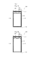
- FIG. 1 is a diagram showing a unit battery 100 constituting a battery pack according to an embodiment of the present invention.
- FIG. 1A is a diagram showing a unit battery 100 that is sealed by forming heat-sealed portions on four sides.
- FIG. 1B is a diagram illustrating a unit battery 100 that is sealed by forming a heat-sealed portion on three sides.
- FIG. 2 is a diagram illustrating a state in which the connection tab 125 is joined to the positive electrode extraction tab 120 of the unit battery 100.
- FIG. 3 is a view showing a state in which holes are provided in the positive and negative lead tabs for series connection of the unit cells 100.
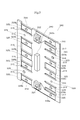
- FIG. 4 is a view for explaining a holder member 200 constituting the battery pack according to the embodiment of the present invention.
- FIG. 1A is a diagram showing a unit battery 100 that is sealed by forming heat-sealed portions on four sides.
- FIG. 1B is a diagram illustrating a unit battery 100 that is sealed by
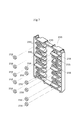
- FIG. 5 is a perspective view of a substrate 300 used for series connection of unit batteries 100 in the battery pack according to the embodiment of the present invention.
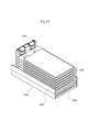
- FIG. 6 is a view for explaining a battery protection member 400 constituting the battery pack according to the embodiment of the present invention.
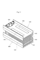
- FIG. 7 is a diagram for explaining a manufacturing process of the battery connection structure 500 constituting the battery pack according to the embodiment of the present invention.
- FIG. 8 is a diagram for explaining a manufacturing process of the battery connection structure 500 constituting the battery pack according to the embodiment of the present invention.
- FIG. 9 is a diagram for explaining a manufacturing process of the battery connection structure 500 constituting the battery pack according to the embodiment of the present invention.
- FIG. 10 is a diagram for explaining a manufacturing process of the battery connection structure 500 constituting the battery pack according to the embodiment of the present invention.
- FIG. 11 is a diagram for explaining a manufacturing process of the battery connection structure 500 constituting the battery pack according to the embodiment of the present invention.
- FIG. 12 is a diagram for explaining a manufacturing process of the battery connection structure 500 constituting the battery pack according to the embodiment of the present invention.
- FIG. 13 is a diagram for explaining a manufacturing process of the battery connection structure 500 constituting the battery pack according to the embodiment of the present invention.
- FIG. 14 is a diagram for explaining a manufacturing process of the battery connection structure 500 constituting the battery pack according to the embodiment of the present invention.
- FIG. 11 is a diagram for explaining a manufacturing process of the battery connection structure 500 constituting the battery pack according to the embodiment of the present invention.
- FIG. 12 is a diagram for explaining a manufacturing process of the battery connection structure 500 constituting the battery pack according to the embodiment of the present invention.
- FIG. 13 is a diagram for explaining
- FIG. 15 is a diagram for explaining a manufacturing process of the battery connection structure 500 constituting the battery pack according to the embodiment of the present invention.
- FIG. 16 is a diagram for explaining a manufacturing process of the battery connection structure 500 constituting the battery pack according to the embodiment of the present invention.
- FIG. 17 is a diagram for explaining a manufacturing process of the battery connection structure 500 constituting the battery pack according to the embodiment of the present invention.
- FIG. 18 is a diagram illustrating a manufacturing process of the battery pack according to the embodiment of the present invention.
- FIG. 19 is a diagram for explaining a manufacturing process of the battery pack according to the embodiment of the present invention.
- FIG. 20 is a diagram illustrating a manufacturing process of the battery pack according to the embodiment of the present invention.
- FIG. 21 is a diagram illustrating a manufacturing process of the battery pack according to the embodiment of the present invention.
- FIG. 22 is a diagram for explaining a manufacturing process of the battery pack according to the embodiment of the present invention.
- FIG. 23 is a diagram illustrating a manufacturing process of the battery pack according to the embodiment of the present invention.
- FIG. 24 is a diagram illustrating a manufacturing process of the battery pack according to the embodiment of the present invention.
- FIG. 25 is a diagram for explaining a manufacturing process of the battery pack according to the embodiment of the present invention.
- FIG. 26 is a diagram illustrating an electric bicycle according to an embodiment of the present invention.
- FIG. 1 is a diagram showing a unit battery 100 constituting a battery pack according to an embodiment of the present invention.
- the unit battery 100 a lithium ion secondary battery that is charged and discharged by moving lithium ions between a negative electrode and a positive electrode is used.
- the unit battery 100 of the present invention is also referred to as a flat battery because its shape is flat.
- the unit battery main body 110 includes a laminated electrode body in which a plurality of sheet-like positive electrodes and a plurality of sheet-like negative electrodes are laminated via separators, and an electrolyte solution (both not shown) having a rectangular film shape in plan view It has a structure housed in the material.
- a positive electrode extraction tab 120 and a negative electrode extraction tab 130 are extracted from the upper end portion 111 of the unit battery main body 110.
- the positive electrode extraction tab 120 and the negative electrode extraction tab 130 are both planar, and are connected to the sheet-shaped positive electrode and the sheet-shaped negative electrode directly or via a lead body in the film-shaped packaging material, respectively.
- a film-shaped packaging material having a heat-sealing resin layer on the inner surface of the battery and laminated on a metal foil such as an aluminum foil having a protective film laminated on the outer surface of the battery is used.
- a member having strength and heat resistance such as nylon and polyethylene terephthalate is provided on the surface located on the outer surface side of the aluminum foil, and heat fusion properties such as polypropylene and polyethylene are good on the inner surface side. Those obtained by laminating materials can be used.
- the inside of the portion 113 is hermetically sealed by heat sealing.
- the material of the positive electrode extraction tab 120 is typically aluminum or an aluminum alloy
- the material of the negative electrode extraction tab 130 is nickel, nickel-plated copper, or nickel-copper clad. It is used for.
- a positive electrode extraction tab 120 made of aluminum and a negative electrode extraction tab 130 made of nickel are used.
- the positive pull-out tab of the unit battery 100 and the negative pull-out tab of the unit battery 100 adjacent to the unit battery 100 are mechanically tightened with a bolt and nut. Secure with and make electrical connection.
- the nickel members are located at the location where the positive electrode extraction tab of the unit cell 100 and the negative electrode extraction tab adjacent to the unit cell 100 are mechanically fixed. The drawer tabs were connected so as to contact each other. A configuration for this will be described.
- the aluminum positive electrode extraction tab 120 in the unit battery 100 has a length a from the upper end portion 111, and the nickel negative electrode extraction tab 130 has a length from the upper end portion 111.
- B (b> a).
- a tab member 125 made of nickel is joined by ultrasonic joining so that the length from the upper end 111 is b to the positive electrode extraction tab 120 made of aluminum having a length a, and is added ( (See FIGS. 2 and 3).
- a hole 127 is provided in the tab member 125 as a positive polarity extraction tab
- a hole 137 is provided in the negative electrode extraction tab 130.
- the entire extraction tab formed by bonding the tab member 125 may be referred to as the positive electrode extraction tab 120.
- the nickel members tab member 125, negative electrode extraction tab 130
- the electrical connection portions of adjacent unit cells are electrically connected by the same kind of metal material, there is no problem of potential difference, and almost no deterioration in conductivity due to the passage of time occurs. .
- FIG. 4A and 4B are views for explaining the holder member 200
- FIG. 4A is a view of the holder member 200 viewed from the first main surface side
- FIG. 4B is a view of the holder member 200 viewed from the second main surface side
- 4C is a view showing a cross section XX ′ of FIG. 4A
- FIG. 4D is a view of the holder member 200 as viewed from the side.
- the holder member 200 is a member made of a synthetic resin such as an ABS resin in which a first surface 210 and a second surface 250 having a front and back relationship with the first surface 210 are formed.
- drawer tab insertion holes 215 are formed side by side from the top to the bottom.
- drawer tab insertion holes 215 are formed side by side from the top to the bottom.
- the pull-out tab insertion hole 215 is used.
- the extraction tab insertion hole 215 is a hole that penetrates from the first surface 210 side to the second surface 250 side, and is a hole through which the extraction tab of the unit battery 100 can be inserted.
- a pull-out tab guide rib 203 is provided on the upper side and the lower side of the first row 211 and the second row 212. Further, the pull-out tab guide portion 213 is sandwiched between the pull-out tab guide ribs 203 on the first row 211 side, and the lead-out tab guide portion 213 is sandwiched between the pull-out tab guide ribs 203 on the second row 212 side. A recess 214 is provided. On the first row 211 side, the pull-out tabs of the unit cells 100 on the end side among the plurality of unit cells 100 connected in series are arranged from the first surface 210 side based on the restriction by the pull-out tab guide ribs 203.
- the pull-out tab of the unit battery 100 that is not on the end side is attached to the holder member 200 so as to be inserted into the pull-out tab insertion hole 215.
- the pull-out tab guide protrusions 220 that sandwich the pull-out tab insertion hole 215 from above and below.
- the substrate 300 is attached to the second surface 250 of the holder member 200.
- substrate 300 the drawer tabs of the adjacent unit battery 100 are folded up, connected, and conduction
- the nut accommodating portion 255 for accommodating the nut 256 is the first row on the second surface 250 side.
- Six are provided on the 211 side and five are provided on the second row 212 side.
- the alignment protrusions 263 are protrusions that are used for alignment when the substrate 300 is attached to the holder member 200, and are arranged one on each of the first row 211 side and the second row 212 side.
- the screw holes 270 used for fixing the substrate 300 and the holder member 200 after the substrate 300 is attached to the holder member 200 using the alignment protrusion 263 described above are provided on the first row 211 side. And one on each of the second row 212 side.
- FIG. 5 is a perspective view of a substrate 300 used for series connection of unit batteries 100 in the battery pack according to the embodiment of the present invention.
- the substrate 300 mainly composed of glass epoxy or the like is used by being attached to the second surface 250 side of the holder member 200, and the outer peripheral shape of the substrate 300 is the second surface 250 of the holder member 200.
- the outer peripheral shape substantially coincides with the outer peripheral shape.
- a drawing tab drawing notch 314 is formed so as to correspond to the drawing tab drawing recess 214 of the holder member 200.
- the substrate 300 is provided with a pull-out tab pull-out hole 315 so as to correspond to the pull-out tab insertion hole 215 of the holder member 200.
- the substrate 300 is provided with partition piece extraction holes 317 so as to correspond to the partition pieces 260 of the holder member 200.
- the substrate 300 is provided with a pull-out tab / partition piece pull-out hole 316 corresponding to both the pull-out tab insertion hole 215 and the partition piece 260 of the holder member 200.
- Each of these holes is a hole penetrating from one main surface of the substrate 300 to the other main surface, and is configured such that the drawer tab of the unit battery 100, the partition piece 260, and the like can be inserted.
- a thin film electrode part 320a, a thin film electrode part 320b, and a thin film electrode part 320c are provided at locations where the extraction tab of the unit battery 100 is fixed to the substrate 300 with bolts and nuts.
- the thin film electrode portion 320 a is electrically connected to the metal positive electrode terminal washer 321 fixed on the substrate 300, and the thin film electrode portion 320 c is used for the metal negative electrode terminal fixed on the substrate 300. Conduction with the electrode washer 322 is achieved. Since the lead tab at the end of the unit battery 100 connected in series is connected to the electrode washer 321 for the positive terminal and the electrode washer 322 for the negative terminal, the electrode washer 321 for the positive terminal and the electrode washer for the negative terminal are connected. 322 is used as a terminal for charging and discharging power as a battery pack. Further, the thin film electrode part 320 b is electrically connected to a terminal part (not shown) of the connector 340, and the potential for monitoring each unit battery 100 can be measured via the connector 340. . The connector 340 can also be configured such that a signal from a temperature measurement sensor (not shown) that measures the temperature of the unit battery 100 can be taken out.
- each of the thin film electrode part 320a, the thin film electrode part 320b, and the thin film electrode part 320c is provided with a pull-out tab connection screw hole 325 through which a pull-out tab connection bolt 257 used for fixing the pull-out tab of the unit battery 100 is inserted. It has been.
- the thin film electrode part 320a and the thin film electrode part 320c one drawer tab of the unit battery 100 at the end of the unit batteries 100 connected in series is fixed.
- two thin film electrode portions 320b are fixed so that the pull-out tabs of adjacent unit cells 100 are folded.
- FIG. 6 is a diagram illustrating a battery protection member 400 constituting the battery pack according to the embodiment of the present invention, and FIG. 6A faces the first plate-like portion 410 to which the main surface of the unit battery 100 is attached.
- 6B is a view of the battery protection member 400, and FIG. 6B is a view of the battery protection member 400 viewed from the upper side of FIG. 6A.
- the battery protection member 400 is used so as to be inserted between the unit batteries 100 placed when the unit battery 100 is placed when the unit battery 100 is placed.
- the battery protection member 400 can be formed of a synthetic resin such as an ABS resin, a polyethylene terephthalate resin, or a polycarbonate resin. By using such a material, the battery protection member 400 can be realized in a lightweight and inexpensive manner.
- the battery protection member 400 can also be formed of a metal member or a synthetic resin member in which good heat conductive material particles are dispersed. By using such a material, the battery protection member 400 can be realized with good thermal conductivity and light weight.
- the metal member is any one selected from aluminum, an aluminum alloy, and copper
- the good heat conductive material particles are any one of aluminum nitride, silicon nitride, and alumina.
- the synthetic resin material examples include an ABS resin, a polyethylene terephthalate resin, and a polycarbonate resin, and materials in which good heat conductive material particles are dispersed can be cited.
- aluminum and aluminum alloys are preferable. In the case of aluminum, aluminum alloy, etc., it is preferable to form an alumite treatment film or an insulating film on the surface. Thereby, even if a voltage application part contacts a protection member, generation
- the first plate-like portion 410 of the battery protection member 400 is a member that is sandwiched between the unit battery 100 and the unit battery 100 connected in series therewith.
- the second plate-shaped portion 440 is provided so as to extend from both ends of the first plate-shaped portion 410 in a direction perpendicular to the first plate-shaped portion 410. Therefore, as shown in FIG. 6B, the battery protection member 400 is a member having an H-shaped cross section. Further, the first plate-like portion 410 has a first notch portion 421 that is the deepest notch portion, and is arranged on both sides of the first notch portion 421, and the deep notch portion next to the first notch portion 421. The second notch portion 422 and the third notch portion 423 which is the shallowest notch portion disposed on both sides of the second notch portion 422 are configured.
- FIGS. 7 to 17 are views for explaining a manufacturing process of the battery connection structure 500 constituting the battery pack according to the embodiment of the present invention.
- the nuts 256 are attached to all the nut accommodating portions 255 provided on the second surface 250 of the holder member 200.
- the inner circumference of the nut accommodating portion 255 is set to such a size that the nut 256 cannot be easily removed when the nut 256 is fitted into the nut accommodating portion 255.
- the alignment projection 263 of the holder member 200 is inserted into the alignment hole 328 of the substrate 300, thereby aligning the holder member 200 and the substrate 300.
- the two board fixing screws 271 are inserted into the board fixing screw holes 329 and screwed into the screw holes 270, so that the holder member 200 and the board 300 are fixed.
- various types of screws can be used as the board fixing screw holes 329.
- the use of tapping screws improves the working efficiency during manufacturing.
- the unit cell 100 is arranged on the first surface 210 of the holder member 200, the negative electrode extraction tab 130 of the unit cell 100 is used, and the thin film electrode of the substrate 300 using the extraction tab drawing recess 214. It bends so that it may contact the part 320b. Further, the positive electrode pull-out tab 120 of the unit cell 100 is bent using the pull-out tab lead-out portion 213 so as to contact the thin film electrode portion 320a of the substrate 300, and the pull-out tab connection bolt 257 is inserted into the hole of the positive electrode pull-out tab 120. 127. The extraction tab connection screw hole 325 is inserted, and the extraction tab connection bolt 257 and the nut 256 accommodated in the nut accommodation portion 255 are screwed together. Thereby, the attachment of the first unit battery 100 is completed.
- the double-sided adhesive tape 460 is used to fix the unit battery 100 that is first attached to the holder member 200 and the unit battery 100 that is secondly attached to the holder member 200.
- the double-sided adhesive tape 460 is provided on the main surface of the unit battery 100 as shown in the figure because a spacer described later is arranged between the two double-sided adhesive tapes 460 to increase productivity. is there.
- the spacer is further disposed on the spacer.
- the two drawer tabs of the second unit battery 100 are inserted into the drawer tab insertion hole 215 so as to slide.
- the pull-out tab guide protrusions 220 are arranged above and below the two pull-out tab insertion holes 215. Furthermore, since the pull-out tab guide protrusions 220 are provided with tapered side surfaces 222, The space between the drawer tab guide protrusions 220 is gradually narrowed. Thereby, the drawer tab of the unit battery can be easily guided to the drawer tab insertion hole 215 of the holder member 200.
- the positive electrode extraction tab 120 of the unit battery 100 that is first attached to the holder member 200 is arranged on the first row 211 side, and the negative electrode extraction tab 130 is arranged on the second row 212 side.
- the positive electrode extraction tab 120 of the unit battery 100 that is secondly attached to the holder member 200 is arranged on the second row 212 side, and the negative electrode extraction tab 130 is arranged on the first row 211 side.
- the positive electrode extraction tabs 120 of the odd-numbered unit cells 100 are arranged on the first row 211 side, and the negative electrode extraction tabs 130 are arranged on the second row 212 side.
- the positive lead tabs 120 of the unit batteries 100 that are evenly attached are arranged on the second row 212 side, and the negative lead tabs 130 are arranged on the first row 211 side.
- the orientation of the pull-out tabs of the adjacent unit cells 100 is different in the placement or stacking direction, it is not necessary to make a diagonal connection in the placement or stacking direction on the substrate 300 side.
- the positive electrode pull-out tab 120 of the unit battery 100 attached second is bent downward in the figure and overlapped with the negative electrode 130 of the unit battery 100 attached first.
- the drawing tab connection bolt 257 is inserted into the hole / drawing tab connection screw hole 325 of each drawing tab, and the drawing tab connection bolt 257 and the nut 256 are screwed together to form the thin film electrode portion 320b.
- a connection portion between the negative electrode extraction tab 130 of the unit battery 100 attached first and the positive electrode extraction tab 120 of the unit battery 100 attached second is formed, and the electrical connection is completed.
- the negative electrode extraction tab 130 of the unit battery 100 attached second is bent upward in the drawing to prepare for connection with the positive electrode extraction tab 120 of the unit battery 100 attached third.
- the battery protection member 400 is attached using a spacer in the same manner as when the second unit battery 100 is attached.
- the upper surface of the second unit battery 100 and the lower surface of the battery protection member 400 are attached by two double-sided adhesive tapes 460.
- two double-sided adhesive tapes 460 are attached to the upper surface of the battery protection member 400.
- the double-sided adhesive tape 460 secures the battery protection member 400 and the unit battery 100 that is thirdly attached to the holder member 200.
- FIG. 14 shows a state in which the third unit battery 100 to the eighth unit battery 100 are sequentially attached to the holder member 200 and the substrate 300 by the same method as described above.
- the drawer tab is folded, and the drawer tab connection bolts 257 are used to connect the drawer tabs of the adjacent unit cells 100 to make electrical connection. Is going.
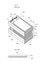
- the process shown in FIG. 15 shows a state where the battery protection member 400 is further attached after the eighth unit battery 100 is attached.
- the two battery protection members 400 are arranged, and the two battery protection member blocks 450 protected by the battery protection members are formed, and each unit is formed.
- the battery 100 is protected from external impacts.
- the unit battery 100 is placed beyond the upper end portion in the height direction of the second plate-like portion 440 from the first plate-like portion 420.
- the battery placed beyond the upper end of the second plate-like part can be placed on either the upper part or the lower part of the figure, or the battery protection member 400 of both.
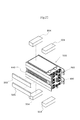
- FIG. 16 shows a state in which the ninth unit battery 100 and the tenth unit battery 100 are further attached to the holder member 200 and the substrate 300 on the first plate-like portion 420 of the battery protection member 400. ing.
- the negative electrode extraction tab 130 of the tenth unit cell 100 is fixed to the substrate 300 thin film electrode portion (not shown) using the extraction tab drawing portion 213. Accordingly, the drawer tabs of the first to tenth unit cells 100 are connected on the substrate 300, and the series connection of the ten unit cells 100 is completed, so that the two battery protection member blocks 450 are connected.
- the provided battery connection structure 500 is completed.
- the unit battery 100 extends beyond the upper end portion in the height direction from the surface of the first plate portion 420 of the second plate portion 440 on the side surface of the battery protection member.
- the side surfaces of some of the unit cells are not covered by the second plate-shaped portion 400. Therefore, ambient air flows from between the second plate-like parts 440 of the upper and lower battery protection members 400 to the placed unit battery 100, and the heat dissipation characteristics of the unit battery 100 are improved.
- the unit battery 100 covered with a film-like exterior material has a heat-sealed portion around it, the side end portion 113 is not bent, and the side end portion 113 is the second end of the battery protection member 400. Since it has the magnitude
- the film-like exterior material is flexible, the heat-sealed portion is formed with a portion having a higher hardness than other portions, so that the force applied from the side end portion 113 has sufficient proof strength. Therefore, it becomes possible to receive vibrations, impacts and the like.
- FIG. 17 is a view of the battery connection structure shown in FIG. 16 as viewed from the substrate side. Charging / discharging of the ten unit batteries 100 connected in series is performed using the electrode washer 321 for positive terminal and the electrode washer 322 for negative terminal attached to the substrate 300. A terminal member 331 is attached to the electrode washer 321 for positive terminal, and a terminal member 332 is attached to the electrode washer 322 for negative electrode terminal.
- the work of inserting the positive and negative pull-out tabs of the plurality of unit batteries 100 into the pull-out tab insertion holes 215 of the holder member 200 is performed.
- the pull-out tabs having different polarities of the plurality of unit batteries 100 are connected to each other on the substrate 300, work efficiency in manufacturing the battery pack is high, and productivity is improved.
- the pull-out tabs of the plurality of unit cells 100 having different polarities are connected to each other on the substrate 300 by the pull-out tab connection bolts 257 and the nuts 256, the plurality of unit cells 100 can be easily electrically connected. This increases the work efficiency in manufacturing the battery pack and improves the productivity.
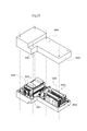
- the discharge terminal mounting recess 611 and the charge terminal mounting recess 612 provided in the first case body 600 are used for the first case body 600 for housing the battery connection structure 500. Then, the discharge terminal 613 and the charge terminal 614 are screwed.
- the first buffer member 621 is attached to the second housing portion 602 of the first case body 600, and the second buffer member 622 is attached to the circuit housing portion 603 with an adhesive or the like.
- the battery pack of the present invention is provided with a drain hole 681 in the upper partition 680 together with a drain hole 682 at the bottom of the battery pack. Since the battery pack is used outdoors, rain or the like enters, and condensation or the like of moisture entering from the outside occurs due to heat generation and cooling of the unit battery and the protection circuit board portion inside the battery pack.
- the drain hole 682 at the bottom not only the drain hole 682 at the bottom, but also the upper partition part 680 such as a section where a protection circuit board that may be affected by moisture is provided is provided with a drain hole 681 inside the battery pack. Since water can be discharged quickly from the water, adverse effects due to water can be avoided.
- the third buffer member 663 is attached to the second housing portion 662 of the second case body 660 with an adhesive or the like.
- the process shown in FIG.21 and FIG.22 performs the process of attaching a shock absorbing material with respect to the battery connection structure 500.
- FIG. In the battery pack according to the present invention, the first battery connection structure 500 and the second battery connection structure 500 are configured to be accommodated in the battery pack.
- a thick fourth buffer member 504 is attached to the unit battery 100 at the end with respect to the first battery connection structure 500, and the second plate-like parts of all battery protection members.
- a fifth buffer member 505 thinner than the fourth buffer member 504 is attached.
- an adhesive or the like is used when attaching the fourth buffer member 504 and the fifth buffer member 505 to each part.
- the fourth buffer member 504 is attached to the unit battery 100 at the end with respect to the second battery connection structure 500, and the second plate-like portion of the battery protection member on one side. Only the 5th buffer member 505 is attached.
- an adhesive or the like is used when attaching the fourth buffer member 504 and the fifth buffer member 505 to each part.
- the discharge terminal 613 and the charge terminal 614 are connected to the protection circuit board 700, and the protection circuit board 700 is screwed to the circuit housing portion 603 of the first case body 600.
- the parts on which circuit components such as tall FETs are mounted are coated with a curable resin having a high pre-curing viscosity
- This part may be coated with a curable resin having a small viscosity before curing.
- the part provided with the coating of the curable resin having a high pre-curing viscosity can be a part including the tallest circuit part on the circuit board surface.
- the first battery connection structure 500A to which the buffer member is attached has a positive CP that is parallel to the bottom surface of the first housing portion 601 with respect to the first housing portion 601, and a negative CM that has a clearance of 1st housing portion 601. It is placed in a direction perpendicular to the bottom surface of the container.
- the second battery connection structure 500B to which the buffer member is attached also has a positive clearance CP with respect to the second housing portion 602 in parallel with the bottom surface of the first housing portion 601, and a negative clearance.
- the CM is arranged and accommodated in a direction perpendicular to the bottom surface of the second accommodation unit 602.
- the positive clearance means that the distance between the outer surfaces of the buffer members is 1.5 mm to 2 mm smaller than the size of the housing portion.
- the second housing portion 602 positioned below has a surface with the shortest interval of a substantially rectangular parallelepiped formed by the outline of the battery connection structure, that is, in this figure, the battery connection.
- a surface orthogonal to the mounting surface of the flat battery of the structure is arranged in parallel to the bottom surface of the second housing portion 602.
- the mounting surface of the flat battery of the battery connection structure is arranged in parallel to the bottom surface of the first housing portion 601 so that the flat shape of the first battery connection structure and the second battery connection structure is obtained.
- the battery connection structure having the same shape and structure is mounted on the first housing portion 601 having a large thickness and the second housing portion 602 having a small thickness, with the mounting surfaces of the flat batteries of the battery arranged perpendicular to each other. To do.
- the battery pack 4 of the present invention is directly attached to the frame 2 that receives vibrations and shocks from the road surface. However, since the battery pack 4 is provided with measures against vibrations and shocks, stable operation is achieved. Can be realized.
- Draw-out tab drawing recess 215 ... Draw-out tab insertion hole, 220 ... Pull-out tab guide protrusions, 221... Top, 222 .. taper side surface, 250. 2nd surface, 255 ... nut housing part, 256 ... nut, 257 ... drawer tab connection bolt, 260 ... partition piece, 263 ... alignment projection, 270 ... screw hole 271 ... Board fixing screw, 300 ... Substrate, 314 ... Drawer tab drawing notch, 315 ... Drawer tab leadout hole, 316 ... Drawer tab / partition piece leadout hole, 317 ... -Partition piece extraction holes, 320a, 320b, 320c ... Thin film electrode portion, 321 ...
Landscapes
- Engineering & Computer Science (AREA)
- Chemical & Material Sciences (AREA)
- Chemical Kinetics & Catalysis (AREA)
- Electrochemistry (AREA)
- General Chemical & Material Sciences (AREA)
- Manufacturing & Machinery (AREA)
- Microelectronics & Electronic Packaging (AREA)
- Materials Engineering (AREA)
- Battery Mounting, Suspending (AREA)
Priority Applications (4)
| Application Number | Priority Date | Filing Date | Title |
|---|---|---|---|
| EP11862604.3A EP2693520B1 (en) | 2011-03-31 | 2011-09-07 | Battery pack and electric bicycle |
| CN201180069815.XA CN103443960B (zh) | 2011-03-31 | 2011-09-07 | 电池组和电动自行车 |
| US14/008,465 US9287591B2 (en) | 2011-03-31 | 2011-09-07 | Battery pack with protective circuit board and electric bicycle including the battery pack |
| US15/019,429 US20160164147A1 (en) | 2011-03-31 | 2016-02-09 | Battery pack with protective circuit board and electric bicycle including the battery pack |
Applications Claiming Priority (2)
| Application Number | Priority Date | Filing Date | Title |
|---|---|---|---|
| JP2011-078306 | 2011-03-31 | ||
| JP2011078306A JP5773412B2 (ja) | 2011-03-31 | 2011-03-31 | 電池パックおよび電動自転車 |
Related Child Applications (2)
| Application Number | Title | Priority Date | Filing Date |
|---|---|---|---|
| US14/008,465 A-371-Of-International US9287591B2 (en) | 2011-03-31 | 2011-09-07 | Battery pack with protective circuit board and electric bicycle including the battery pack |
| US15/019,429 Continuation US20160164147A1 (en) | 2011-03-31 | 2016-02-09 | Battery pack with protective circuit board and electric bicycle including the battery pack |
Publications (1)
| Publication Number | Publication Date |
|---|---|
| WO2012131800A1 true WO2012131800A1 (ja) | 2012-10-04 |
Family
ID=46929647
Family Applications (1)
| Application Number | Title | Priority Date | Filing Date |
|---|---|---|---|
| PCT/JP2011/005030 WO2012131800A1 (ja) | 2011-03-31 | 2011-09-07 | 電池パックおよび電動自転車 |
Country Status (5)
| Country | Link |
|---|---|
| US (2) | US9287591B2 (zh) |
| EP (1) | EP2693520B1 (zh) |
| JP (1) | JP5773412B2 (zh) |
| CN (1) | CN103443960B (zh) |
| WO (1) | WO2012131800A1 (zh) |
Cited By (1)
| Publication number | Priority date | Publication date | Assignee | Title |
|---|---|---|---|---|
| JPWO2017057207A1 (ja) * | 2015-10-02 | 2018-06-07 | 日立オートモティブシステムズ株式会社 | 組電池 |
Families Citing this family (20)
| Publication number | Priority date | Publication date | Assignee | Title |
|---|---|---|---|---|
| DE202011102068U1 (de) | 2011-06-07 | 2012-09-10 | Voltwerk Electronics Gmbh | Hochsetzsteller |
| DE102015206182A1 (de) | 2014-05-06 | 2015-11-12 | Robert Bosch Gmbh | Isolieren von aneinanderliegenden Lithium-Ionen-Akkumulatoren durch komplettes Umspritzen/Ausgießen der Behälter in einer Vorrichtung |
| KR102208441B1 (ko) * | 2014-06-13 | 2021-01-27 | 삼성전자주식회사 | 화면을 포함하는 전자 장치 |
| US11569541B2 (en) * | 2014-06-30 | 2023-01-31 | Black & Decker Inc. | Battery pack for a cordless power tool |
| DE102014226828B4 (de) * | 2014-12-22 | 2019-02-07 | Biketec Ag | Fahrradrahmen, Elektrofahrrad und Energiespeicher |
| KR101779947B1 (ko) * | 2015-02-27 | 2017-10-10 | 주식회사 엘지화학 | 결로 예방 구조의 전압 센싱부를 포함하는 전지모듈 |
| JP6113218B2 (ja) | 2015-04-16 | 2017-04-12 | ヤマハ発動機株式会社 | バッテリ、バッテリケース及び電動車両 |
| US10388916B2 (en) | 2015-09-18 | 2019-08-20 | Gs Yuasa International Ltd. | Energy storage apparatus |
| KR101943542B1 (ko) | 2015-09-21 | 2019-01-29 | 주식회사 엘지화학 | 배터리 모듈 및 이를 포함하는 배터리 팩 |
| JP6782136B2 (ja) * | 2016-09-26 | 2020-11-11 | 株式会社エンビジョンAescジャパン | スペーサおよび組電池 |
| CN109804484B (zh) * | 2016-10-03 | 2021-12-14 | 株式会社村田制作所 | 电池组、电子设备、电动车辆、电动工具及电力存储系统 |
| US11251488B2 (en) | 2017-03-07 | 2022-02-15 | Envision Aesc Japan Ltd. | Battery pack and method for manufacturing battery pack |
| CN110366790B (zh) * | 2017-03-07 | 2023-05-09 | 远景Aesc日本有限公司 | 电池组以及电池组的制造方法 |
| CN110600927A (zh) * | 2018-06-30 | 2019-12-20 | 中航光电科技股份有限公司 | 电池包组件及其连接器、插座 |
| US11495846B2 (en) * | 2018-08-28 | 2022-11-08 | Donald P. H. Wu | Secondary aggregate battery with spatial separation of operation temperatures |
| JP7133491B2 (ja) * | 2019-01-31 | 2022-09-08 | マレリ株式会社 | 組電池及び塗布方法 |
| JP7264778B2 (ja) * | 2019-09-09 | 2023-04-25 | 株式会社クボタ | 筐体および電動草刈機 |
| CN111446408A (zh) * | 2020-05-14 | 2020-07-24 | 中航锂电(洛阳)有限公司 | 电芯、电池及电池制造方法 |
| TWI761927B (zh) * | 2020-06-30 | 2022-04-21 | 盔甲奈米科技股份有限公司 | 具有奈米複合塗層的電池芯模組 |
| CN113363614B (zh) * | 2021-06-10 | 2023-02-24 | 东莞新能安科技有限公司 | 一种电池包及用电设备 |
Citations (9)
| Publication number | Priority date | Publication date | Assignee | Title |
|---|---|---|---|---|
| JPH0491443A (ja) * | 1990-08-01 | 1992-03-24 | Toshiba Corp | 半導体装置の製造方法 |
| JPH0590957U (ja) * | 1992-05-11 | 1993-12-10 | 株式会社富士通ゼネラル | フリップチップのコーティング構造 |
| JPH11204571A (ja) * | 1998-01-09 | 1999-07-30 | Matsushita Electric Ind Co Ltd | 機能素子の実装構造体とその製造方法 |
| JPH11251343A (ja) * | 1998-02-27 | 1999-09-17 | Nec Corp | 素子の樹脂封止構造、及び封止方法 |
| JP2004079219A (ja) * | 2002-08-12 | 2004-03-11 | Matsushita Electric Ind Co Ltd | バッテリ装置及び電動自転車 |
| JP2005209368A (ja) * | 2004-01-20 | 2005-08-04 | Matsushita Electric Ind Co Ltd | 電池パック |
| JP2007257901A (ja) | 2006-03-22 | 2007-10-04 | Matsushita Electric Ind Co Ltd | バッテリ装置および電動自転車 |
| WO2008007767A1 (en) * | 2006-07-13 | 2008-01-17 | Gs Yuasa Corporation | Assembled battery formed by stacking a plurality of flat cells |
| JP2008047371A (ja) * | 2006-08-11 | 2008-02-28 | Toshiba Corp | 組電池および組電池の充放電方法 |
Family Cites Families (35)
| Publication number | Priority date | Publication date | Assignee | Title |
|---|---|---|---|---|
| JPH04534Y2 (zh) | 1984-10-15 | 1992-01-09 | ||
| JPH0416373Y2 (zh) | 1987-05-12 | 1992-04-13 | ||
| US5379186A (en) * | 1993-07-06 | 1995-01-03 | Motorola, Inc. | Encapsulated electronic component having a heat diffusing layer |
| FR2740608B1 (fr) * | 1995-10-25 | 1997-12-19 | Giat Ind Sa | Procede pour deposer un revetement de protection sur les composants d'une carte electronique |
| US6665192B2 (en) * | 1997-02-18 | 2003-12-16 | Koninklijke Philips Electronics N.V. | Synthetic resin capping layer on a printed circuit |
| US6127038A (en) * | 1997-12-11 | 2000-10-03 | American Meter Company | Printed circuit board coating and method |
| JP2000021379A (ja) | 1998-07-06 | 2000-01-21 | Kobe Steel Ltd | 電池収納機構およびその機構を有する携帯型電子装置 |
| JP3594078B2 (ja) | 2000-10-12 | 2004-11-24 | 日本電気株式会社 | 二次電池および乾電池を使用可能な情報処理装置および該情報処理装置に着脱可能な乾電池パック |
| JP4173674B2 (ja) | 2002-03-28 | 2008-10-29 | Tdk株式会社 | 電気化学デバイスモジュール |
| JP3649213B2 (ja) | 2002-07-30 | 2005-05-18 | 日産自動車株式会社 | モジュール電池 |
| US7157882B2 (en) | 2002-11-22 | 2007-01-02 | Milwaukee Electric Tool Corporation | Method and system for battery protection employing a selectively-actuated switch |
| JP2004327311A (ja) | 2003-04-25 | 2004-11-18 | Toyota Motor Corp | 電池の接続構造及び接続方法 |
| JP3882818B2 (ja) | 2004-01-15 | 2007-02-21 | ソニー株式会社 | 電池パック |
| US7507499B2 (en) | 2004-05-24 | 2009-03-24 | General Motors Corporation | Battery pack arrangements |
| CN100555711C (zh) * | 2004-07-23 | 2009-10-28 | 索尼株式会社 | 电池组 |
| JP4765439B2 (ja) | 2004-07-23 | 2011-09-07 | ソニー株式会社 | 電池パック |
| US20070289129A1 (en) * | 2004-08-06 | 2007-12-20 | Wing Kenneth E | Selective Encapsulation of Electronic Components |
| US7301303B1 (en) | 2004-08-16 | 2007-11-27 | International Specialty Services, Inc. | Portable battery jump start in a soft-sided carrying case |
| KR100624943B1 (ko) * | 2004-10-28 | 2006-09-15 | 삼성에스디아이 주식회사 | 배터리 팩의 보호회로기판 |
| JP4601432B2 (ja) | 2005-01-12 | 2010-12-22 | 三洋電機株式会社 | パック電池 |
| JP4439456B2 (ja) | 2005-03-24 | 2010-03-24 | 株式会社東芝 | 電池パック及び自動車 |
| CN100444430C (zh) | 2005-06-16 | 2008-12-17 | 日产自动车株式会社 | 扁平型电池及采用该扁平型电池的电池组 |
| JP5098318B2 (ja) | 2006-12-11 | 2012-12-12 | 日産自動車株式会社 | 電池モジュール |
| JP5094175B2 (ja) | 2007-03-23 | 2012-12-12 | Necエナジーデバイス株式会社 | リチウムイオン二次電池パック |
| JP2009054297A (ja) | 2007-08-23 | 2009-03-12 | Toshiba Corp | 電池パック |
| JP4508221B2 (ja) | 2007-08-27 | 2010-07-21 | 豊田合成株式会社 | 組電池装置 |
| JP5111099B2 (ja) * | 2007-12-28 | 2012-12-26 | シャープ株式会社 | 電池パック |
| JP2009224227A (ja) | 2008-03-17 | 2009-10-01 | Toshiba Corp | 電池モジュールおよびこれを備えたバッテリパック |
| JP2009252553A (ja) | 2008-04-07 | 2009-10-29 | Furukawa Battery Co Ltd:The | 組電池モジュール |
| CN101521265A (zh) | 2008-10-10 | 2009-09-02 | 比亚迪股份有限公司 | 一种电动汽车用动力电池包及其电池系统 |
| JP2010109011A (ja) * | 2008-10-28 | 2010-05-13 | Nec Electronics Corp | 半導体装置およびその製造方法 |
| DE102009008222A1 (de) | 2009-02-10 | 2010-08-12 | Li-Tec Battery Gmbh | Batteriekühlung |
| KR101145719B1 (ko) | 2009-04-01 | 2012-05-14 | 주식회사 엘지화학 | 우수한 방열 특성의 전지모듈 및 중대형 전지팩 |
| JP2011034775A (ja) * | 2009-07-31 | 2011-02-17 | Sanyo Electric Co Ltd | 組電池の冷却構造、及び、バッテリーシステム |
| CN102484232B (zh) | 2009-09-02 | 2017-09-29 | Nec能源元器件株式会社 | 组装电池模块 |
-
2011
- 2011-03-31 JP JP2011078306A patent/JP5773412B2/ja active Active
- 2011-09-07 EP EP11862604.3A patent/EP2693520B1/en active Active
- 2011-09-07 CN CN201180069815.XA patent/CN103443960B/zh active Active
- 2011-09-07 US US14/008,465 patent/US9287591B2/en active Active
- 2011-09-07 WO PCT/JP2011/005030 patent/WO2012131800A1/ja active Application Filing
-
2016
- 2016-02-09 US US15/019,429 patent/US20160164147A1/en not_active Abandoned
Patent Citations (9)
| Publication number | Priority date | Publication date | Assignee | Title |
|---|---|---|---|---|
| JPH0491443A (ja) * | 1990-08-01 | 1992-03-24 | Toshiba Corp | 半導体装置の製造方法 |
| JPH0590957U (ja) * | 1992-05-11 | 1993-12-10 | 株式会社富士通ゼネラル | フリップチップのコーティング構造 |
| JPH11204571A (ja) * | 1998-01-09 | 1999-07-30 | Matsushita Electric Ind Co Ltd | 機能素子の実装構造体とその製造方法 |
| JPH11251343A (ja) * | 1998-02-27 | 1999-09-17 | Nec Corp | 素子の樹脂封止構造、及び封止方法 |
| JP2004079219A (ja) * | 2002-08-12 | 2004-03-11 | Matsushita Electric Ind Co Ltd | バッテリ装置及び電動自転車 |
| JP2005209368A (ja) * | 2004-01-20 | 2005-08-04 | Matsushita Electric Ind Co Ltd | 電池パック |
| JP2007257901A (ja) | 2006-03-22 | 2007-10-04 | Matsushita Electric Ind Co Ltd | バッテリ装置および電動自転車 |
| WO2008007767A1 (en) * | 2006-07-13 | 2008-01-17 | Gs Yuasa Corporation | Assembled battery formed by stacking a plurality of flat cells |
| JP2008047371A (ja) * | 2006-08-11 | 2008-02-28 | Toshiba Corp | 組電池および組電池の充放電方法 |
Non-Patent Citations (1)
| Title |
|---|
| See also references of EP2693520A4 |
Cited By (1)
| Publication number | Priority date | Publication date | Assignee | Title |
|---|---|---|---|---|
| JPWO2017057207A1 (ja) * | 2015-10-02 | 2018-06-07 | 日立オートモティブシステムズ株式会社 | 組電池 |
Also Published As
| Publication number | Publication date |
|---|---|
| US9287591B2 (en) | 2016-03-15 |
| CN103443960B (zh) | 2016-05-11 |
| JP5773412B2 (ja) | 2015-09-02 |
| EP2693520A1 (en) | 2014-02-05 |
| US20140017521A1 (en) | 2014-01-16 |
| US20160164147A1 (en) | 2016-06-09 |
| EP2693520A4 (en) | 2014-09-03 |
| JP2012212599A (ja) | 2012-11-01 |
| EP2693520B1 (en) | 2015-12-09 |
| CN103443960A (zh) | 2013-12-11 |
Similar Documents
| Publication | Publication Date | Title |
|---|---|---|
| JP5773412B2 (ja) | 電池パックおよび電動自転車 | |
| WO2012131799A1 (ja) | 電池パックおよび電動自転車 | |
| JP5761742B2 (ja) | 電池パック | |
| WO2012131801A1 (ja) | 電池パック | |
| JP5831924B2 (ja) | 電池パック | |
| KR20070025391A (ko) | 이차전지 및 이를 포함하는 전지모듈 | |
| WO2012131798A1 (ja) | 電池パックおよび電動自転車 | |
| JP2012212608A (ja) | 電池パック | |
| JP2012212593A (ja) | 電池パックおよび電動自転車 | |
| JP5858457B2 (ja) | 電池パックおよび電動自転車 | |
| JP5700543B2 (ja) | 電池パック | |
| JP5709215B2 (ja) | 電池パック | |
| JP5831922B2 (ja) | 電池パックおよび電動自転車 | |
| JP2012212602A (ja) | 電池パック | |
| JP5709214B2 (ja) | 電池パック | |
| JP5813978B2 (ja) | 電池パックおよび電動自転車 | |
| JP5765769B2 (ja) | 電池パック | |
| JP2012212589A (ja) | 電池パックおよび電動自転車 | |
| JP2012212591A (ja) | 電池パックおよび電動自転車 | |
| JP2012212606A (ja) | 電池パック | |
| JP5777142B2 (ja) | 電池パックおよび電動自転車 | |
| JP5794615B2 (ja) | 電池パックおよび電動自転車 | |
| JP5796765B2 (ja) | 電池パックおよび電動自転車 | |
| JP2015228382A (ja) | 電池パックおよび電動自転車 | |
| JP2012212592A (ja) | 電池パックおよび電動自転車 |
Legal Events
| Date | Code | Title | Description |
|---|---|---|---|
| WWE | Wipo information: entry into national phase |
Ref document number: 201180069815.X Country of ref document: CN |
|
| 121 | Ep: the epo has been informed by wipo that ep was designated in this application |
Ref document number: 11862604 Country of ref document: EP Kind code of ref document: A1 |
|
| WWE | Wipo information: entry into national phase |
Ref document number: 2011862604 Country of ref document: EP |
|
| WWE | Wipo information: entry into national phase |
Ref document number: 14008465 Country of ref document: US |
|
| NENP | Non-entry into the national phase |
Ref country code: DE |