WO2012127668A1 - 車両用駆動装置 - Google Patents
車両用駆動装置 Download PDFInfo
- Publication number
- WO2012127668A1 WO2012127668A1 PCT/JP2011/057053 JP2011057053W WO2012127668A1 WO 2012127668 A1 WO2012127668 A1 WO 2012127668A1 JP 2011057053 W JP2011057053 W JP 2011057053W WO 2012127668 A1 WO2012127668 A1 WO 2012127668A1
- Authority
- WO
- WIPO (PCT)
- Prior art keywords
- electric motor
- gear
- clutch
- vehicle
- output
- Prior art date
- Legal status (The legal status is an assumption and is not a legal conclusion. Google has not performed a legal analysis and makes no representation as to the accuracy of the status listed.)
- Ceased
Links
Images





Classifications
-
- F—MECHANICAL ENGINEERING; LIGHTING; HEATING; WEAPONS; BLASTING
- F16—ENGINEERING ELEMENTS AND UNITS; GENERAL MEASURES FOR PRODUCING AND MAINTAINING EFFECTIVE FUNCTIONING OF MACHINES OR INSTALLATIONS; THERMAL INSULATION IN GENERAL
- F16H—GEARING
- F16H3/00—Toothed gearings for conveying rotary motion with variable gear ratio or for reversing rotary motion
- F16H3/02—Toothed gearings for conveying rotary motion with variable gear ratio or for reversing rotary motion without gears having orbital motion
- F16H3/08—Toothed gearings for conveying rotary motion with variable gear ratio or for reversing rotary motion without gears having orbital motion exclusively or essentially with continuously meshing gears, that can be disengaged from their shafts
- F16H3/087—Toothed gearings for conveying rotary motion with variable gear ratio or for reversing rotary motion without gears having orbital motion exclusively or essentially with continuously meshing gears, that can be disengaged from their shafts characterised by the disposition of the gears
- F16H3/089—Toothed gearings for conveying rotary motion with variable gear ratio or for reversing rotary motion without gears having orbital motion exclusively or essentially with continuously meshing gears, that can be disengaged from their shafts characterised by the disposition of the gears all of the meshing gears being supported by a pair of parallel shafts, one being the input shaft and the other the output shaft, there being no countershaft involved
-
- B—PERFORMING OPERATIONS; TRANSPORTING
- B60—VEHICLES IN GENERAL
- B60K—ARRANGEMENT OR MOUNTING OF PROPULSION UNITS OR OF TRANSMISSIONS IN VEHICLES; ARRANGEMENT OR MOUNTING OF PLURAL DIVERSE PRIME-MOVERS IN VEHICLES; AUXILIARY DRIVES FOR VEHICLES; INSTRUMENTATION OR DASHBOARDS FOR VEHICLES; ARRANGEMENTS IN CONNECTION WITH COOLING, AIR INTAKE, GAS EXHAUST OR FUEL SUPPLY OF PROPULSION UNITS IN VEHICLES
- B60K17/00—Arrangement or mounting of transmissions in vehicles
- B60K17/04—Arrangement or mounting of transmissions in vehicles characterised by arrangement, location or kind of gearing
- B60K17/06—Arrangement or mounting of transmissions in vehicles characterised by arrangement, location or kind of gearing of change-speed gearing
-
- B—PERFORMING OPERATIONS; TRANSPORTING
- B60—VEHICLES IN GENERAL
- B60K—ARRANGEMENT OR MOUNTING OF PROPULSION UNITS OR OF TRANSMISSIONS IN VEHICLES; ARRANGEMENT OR MOUNTING OF PLURAL DIVERSE PRIME-MOVERS IN VEHICLES; AUXILIARY DRIVES FOR VEHICLES; INSTRUMENTATION OR DASHBOARDS FOR VEHICLES; ARRANGEMENTS IN CONNECTION WITH COOLING, AIR INTAKE, GAS EXHAUST OR FUEL SUPPLY OF PROPULSION UNITS IN VEHICLES
- B60K1/00—Arrangement or mounting of electrical propulsion units
-
- B—PERFORMING OPERATIONS; TRANSPORTING
- B60—VEHICLES IN GENERAL
- B60K—ARRANGEMENT OR MOUNTING OF PROPULSION UNITS OR OF TRANSMISSIONS IN VEHICLES; ARRANGEMENT OR MOUNTING OF PLURAL DIVERSE PRIME-MOVERS IN VEHICLES; AUXILIARY DRIVES FOR VEHICLES; INSTRUMENTATION OR DASHBOARDS FOR VEHICLES; ARRANGEMENTS IN CONNECTION WITH COOLING, AIR INTAKE, GAS EXHAUST OR FUEL SUPPLY OF PROPULSION UNITS IN VEHICLES
- B60K17/00—Arrangement or mounting of transmissions in vehicles
- B60K17/02—Arrangement or mounting of transmissions in vehicles characterised by arrangement, location, or kind of clutch
-
- B—PERFORMING OPERATIONS; TRANSPORTING
- B60—VEHICLES IN GENERAL
- B60K—ARRANGEMENT OR MOUNTING OF PROPULSION UNITS OR OF TRANSMISSIONS IN VEHICLES; ARRANGEMENT OR MOUNTING OF PLURAL DIVERSE PRIME-MOVERS IN VEHICLES; AUXILIARY DRIVES FOR VEHICLES; INSTRUMENTATION OR DASHBOARDS FOR VEHICLES; ARRANGEMENTS IN CONNECTION WITH COOLING, AIR INTAKE, GAS EXHAUST OR FUEL SUPPLY OF PROPULSION UNITS IN VEHICLES
- B60K17/00—Arrangement or mounting of transmissions in vehicles
- B60K17/34—Arrangement or mounting of transmissions in vehicles for driving both front and rear wheels, e.g. four wheel drive vehicles
- B60K17/356—Arrangement or mounting of transmissions in vehicles for driving both front and rear wheels, e.g. four wheel drive vehicles having fluid or electric motor, for driving one or more wheels
-
- B—PERFORMING OPERATIONS; TRANSPORTING
- B60—VEHICLES IN GENERAL
- B60L—PROPULSION OF ELECTRICALLY-PROPELLED VEHICLES; SUPPLYING ELECTRIC POWER FOR AUXILIARY EQUIPMENT OF ELECTRICALLY-PROPELLED VEHICLES; ELECTRODYNAMIC BRAKE SYSTEMS FOR VEHICLES IN GENERAL; MAGNETIC SUSPENSION OR LEVITATION FOR VEHICLES; MONITORING OPERATING VARIABLES OF ELECTRICALLY-PROPELLED VEHICLES; ELECTRIC SAFETY DEVICES FOR ELECTRICALLY-PROPELLED VEHICLES
- B60L15/00—Methods, circuits, or devices for controlling the traction-motor speed of electrically-propelled vehicles
- B60L15/20—Methods, circuits, or devices for controlling the traction-motor speed of electrically-propelled vehicles for control of the vehicle or its driving motor to achieve a desired performance, e.g. speed, torque, programmed variation of speed
- B60L15/2054—Methods, circuits, or devices for controlling the traction-motor speed of electrically-propelled vehicles for control of the vehicle or its driving motor to achieve a desired performance, e.g. speed, torque, programmed variation of speed by controlling transmissions or clutches
-
- B—PERFORMING OPERATIONS; TRANSPORTING
- B60—VEHICLES IN GENERAL
- B60L—PROPULSION OF ELECTRICALLY-PROPELLED VEHICLES; SUPPLYING ELECTRIC POWER FOR AUXILIARY EQUIPMENT OF ELECTRICALLY-PROPELLED VEHICLES; ELECTRODYNAMIC BRAKE SYSTEMS FOR VEHICLES IN GENERAL; MAGNETIC SUSPENSION OR LEVITATION FOR VEHICLES; MONITORING OPERATING VARIABLES OF ELECTRICALLY-PROPELLED VEHICLES; ELECTRIC SAFETY DEVICES FOR ELECTRICALLY-PROPELLED VEHICLES
- B60L50/00—Electric propulsion with power supplied within the vehicle
-
- F—MECHANICAL ENGINEERING; LIGHTING; HEATING; WEAPONS; BLASTING
- F16—ENGINEERING ELEMENTS AND UNITS; GENERAL MEASURES FOR PRODUCING AND MAINTAINING EFFECTIVE FUNCTIONING OF MACHINES OR INSTALLATIONS; THERMAL INSULATION IN GENERAL
- F16H—GEARING
- F16H3/00—Toothed gearings for conveying rotary motion with variable gear ratio or for reversing rotary motion
- F16H3/02—Toothed gearings for conveying rotary motion with variable gear ratio or for reversing rotary motion without gears having orbital motion
- F16H3/08—Toothed gearings for conveying rotary motion with variable gear ratio or for reversing rotary motion without gears having orbital motion exclusively or essentially with continuously meshing gears, that can be disengaged from their shafts
- F16H3/087—Toothed gearings for conveying rotary motion with variable gear ratio or for reversing rotary motion without gears having orbital motion exclusively or essentially with continuously meshing gears, that can be disengaged from their shafts characterised by the disposition of the gears
- F16H3/093—Toothed gearings for conveying rotary motion with variable gear ratio or for reversing rotary motion without gears having orbital motion exclusively or essentially with continuously meshing gears, that can be disengaged from their shafts characterised by the disposition of the gears with two or more countershafts
-
- B—PERFORMING OPERATIONS; TRANSPORTING
- B60—VEHICLES IN GENERAL
- B60K—ARRANGEMENT OR MOUNTING OF PROPULSION UNITS OR OF TRANSMISSIONS IN VEHICLES; ARRANGEMENT OR MOUNTING OF PLURAL DIVERSE PRIME-MOVERS IN VEHICLES; AUXILIARY DRIVES FOR VEHICLES; INSTRUMENTATION OR DASHBOARDS FOR VEHICLES; ARRANGEMENTS IN CONNECTION WITH COOLING, AIR INTAKE, GAS EXHAUST OR FUEL SUPPLY OF PROPULSION UNITS IN VEHICLES
- B60K1/00—Arrangement or mounting of electrical propulsion units
- B60K2001/001—Arrangement or mounting of electrical propulsion units one motor mounted on a propulsion axle for rotating right and left wheels of this axle
-
- F—MECHANICAL ENGINEERING; LIGHTING; HEATING; WEAPONS; BLASTING
- F16—ENGINEERING ELEMENTS AND UNITS; GENERAL MEASURES FOR PRODUCING AND MAINTAINING EFFECTIVE FUNCTIONING OF MACHINES OR INSTALLATIONS; THERMAL INSULATION IN GENERAL
- F16H—GEARING
- F16H2200/00—Transmissions for multiple ratios
- F16H2200/0021—Transmissions for multiple ratios specially adapted for electric vehicles
-
- F—MECHANICAL ENGINEERING; LIGHTING; HEATING; WEAPONS; BLASTING
- F16—ENGINEERING ELEMENTS AND UNITS; GENERAL MEASURES FOR PRODUCING AND MAINTAINING EFFECTIVE FUNCTIONING OF MACHINES OR INSTALLATIONS; THERMAL INSULATION IN GENERAL
- F16H—GEARING
- F16H2200/00—Transmissions for multiple ratios
- F16H2200/003—Transmissions for multiple ratios characterised by the number of forward speeds
- F16H2200/0034—Transmissions for multiple ratios characterised by the number of forward speeds the gear ratios comprising two forward speeds
-
- F—MECHANICAL ENGINEERING; LIGHTING; HEATING; WEAPONS; BLASTING
- F16—ENGINEERING ELEMENTS AND UNITS; GENERAL MEASURES FOR PRODUCING AND MAINTAINING EFFECTIVE FUNCTIONING OF MACHINES OR INSTALLATIONS; THERMAL INSULATION IN GENERAL
- F16H—GEARING
- F16H2200/00—Transmissions for multiple ratios
- F16H2200/003—Transmissions for multiple ratios characterised by the number of forward speeds
- F16H2200/0043—Transmissions for multiple ratios characterised by the number of forward speeds the gear ratios comprising four forward speeds
-
- F—MECHANICAL ENGINEERING; LIGHTING; HEATING; WEAPONS; BLASTING
- F16—ENGINEERING ELEMENTS AND UNITS; GENERAL MEASURES FOR PRODUCING AND MAINTAINING EFFECTIVE FUNCTIONING OF MACHINES OR INSTALLATIONS; THERMAL INSULATION IN GENERAL
- F16H—GEARING
- F16H2200/00—Transmissions for multiple ratios
- F16H2200/003—Transmissions for multiple ratios characterised by the number of forward speeds
- F16H2200/0052—Transmissions for multiple ratios characterised by the number of forward speeds the gear ratios comprising six forward speeds
-
- F—MECHANICAL ENGINEERING; LIGHTING; HEATING; WEAPONS; BLASTING
- F16—ENGINEERING ELEMENTS AND UNITS; GENERAL MEASURES FOR PRODUCING AND MAINTAINING EFFECTIVE FUNCTIONING OF MACHINES OR INSTALLATIONS; THERMAL INSULATION IN GENERAL
- F16H—GEARING
- F16H3/00—Toothed gearings for conveying rotary motion with variable gear ratio or for reversing rotary motion
- F16H3/006—Toothed gearings for conveying rotary motion with variable gear ratio or for reversing rotary motion power being selectively transmitted by parallel flow paths, e.g. dual clutch transmissions
-
- Y—GENERAL TAGGING OF NEW TECHNOLOGICAL DEVELOPMENTS; GENERAL TAGGING OF CROSS-SECTIONAL TECHNOLOGIES SPANNING OVER SEVERAL SECTIONS OF THE IPC; TECHNICAL SUBJECTS COVERED BY FORMER USPC CROSS-REFERENCE ART COLLECTIONS [XRACs] AND DIGESTS
- Y02—TECHNOLOGIES OR APPLICATIONS FOR MITIGATION OR ADAPTATION AGAINST CLIMATE CHANGE
- Y02T—CLIMATE CHANGE MITIGATION TECHNOLOGIES RELATED TO TRANSPORTATION
- Y02T10/00—Road transport of goods or passengers
- Y02T10/60—Other road transportation technologies with climate change mitigation effect
- Y02T10/64—Electric machine technologies in electromobility
-
- Y—GENERAL TAGGING OF NEW TECHNOLOGICAL DEVELOPMENTS; GENERAL TAGGING OF CROSS-SECTIONAL TECHNOLOGIES SPANNING OVER SEVERAL SECTIONS OF THE IPC; TECHNICAL SUBJECTS COVERED BY FORMER USPC CROSS-REFERENCE ART COLLECTIONS [XRACs] AND DIGESTS
- Y02—TECHNOLOGIES OR APPLICATIONS FOR MITIGATION OR ADAPTATION AGAINST CLIMATE CHANGE
- Y02T—CLIMATE CHANGE MITIGATION TECHNOLOGIES RELATED TO TRANSPORTATION
- Y02T10/00—Road transport of goods or passengers
- Y02T10/60—Other road transportation technologies with climate change mitigation effect
- Y02T10/72—Electric energy management in electromobility
Definitions
- the present invention relates to a mechanical configuration of a vehicle drive device including an electric motor that outputs power toward drive wheels.
- a vehicle drive device including an electric motor that outputs power toward a drive wheel is known.
- this is the electric vehicle drive device described in Patent Document 1.
- an output rotating member of the electric motor that is, one end portion of the electric motor output shaft is connected to a drive wheel via a speed reduction mechanism.
- the other end of the motor output shaft is not connected to the drive wheel. That is, the power of the electric motor is transmitted toward the drive wheel only from one end portion of the motor output shaft, but is not transmitted toward the drive wheel from the other end portion of the motor output shaft.
- FIG. 9 is an image diagram showing a state in which a conventional drive device for an electric vehicle is mounted on a vehicle.
- the power of the electric motor 900 is transmitted to the drive wheels 904 via the transmission 902. As shown in FIG.
- the present invention has been made against the background of the above circumstances, and the object of the present invention is to design constraints on the mounting position of the motor when the motor that outputs power toward the drive wheels is mounted on the vehicle.
- An object of the present invention is to provide a vehicle drive device that can reduce the above-mentioned problem.
- the gist of the first invention for achieving the above object is (a) a vehicle drive device including an electric motor that outputs power to drive wheels, and (b) an output rotating member of the electric motor Power is output from one end and the other end of the output rotating member. (C) One end and the other end of the output rotating member are detachably connected to the drive wheel, respectively. (D) The output A speed change is performed between the electric motor and the driving wheel by selectively connecting one end and the other end of the rotating member to the driving wheel.
- the power of the electric motor is selectively output from either the one end side or the other end side of the electric motor. It can suppress that the arrangement
- the gist of the second invention is the vehicle drive device according to the first invention, wherein (a) the power of the electric motor is transmitted to the driving wheels and parallel to the axial direction of the output rotating member of the electric motor. (B) the electric motor is provided so as to overlap with the differential gear device in a direction perpendicular to the rotational axis of the differential gear device.
- the electric motor and the differential gear device are accommodated in one casing, and all or a part of the differential gear device is immersed in oil in the casing.
- the gist of the third invention is the vehicle drive device according to the second invention, wherein the electric motor is disposed in front of the vehicle with respect to the differential gear device. .
- the vehicle may travel backward, but most of the vehicle travel is forward travel, and the electric motor is driven by air introduced from the front of the vehicle during the forward travel. Therefore, it is possible to increase the cooling performance of the electric motor as compared with the case where the electric motor is arranged behind the vehicle with respect to the differential gear device. .
- the vehicle drive device according to any one of the first to third aspects, wherein: (a) one end portion of the output rotation member is connected to the drive wheel. A detachable first power connection / disconnection device is interposed between a gear closest to the electric motor and one end of the power transmission path between the one end and the drive wheel, and (b) A second power connecting / disconnecting device capable of separating the other end portion of the output rotating member from the drive wheel, a gear closest to the electric motor in a power transmission path between the other end portion and the drive wheel; It is characterized by being interposed between the end portions.
- the first power connection / disconnection device connects the one end to the drive wheel, the power transmission from the output rotating member of the motor is driven from the other end to the other end.
- the second power connection / disconnection device cuts off the other end portion.
- power transmission from the output rotating member of the motor is transmitted from the one end to a gear closest to the motor in a power transmission path between the one end and the drive wheel.
- the subject matter of the fifth invention is the vehicle drive device according to any one of the first invention to the fourth invention, wherein (a) the speed change between the electric motor and the drive wheel is: One gear is selected from a plurality of predetermined gears, (b) a first gear that establishes an odd gear among the plurality of predetermined gears, and the output rotation A first power connecting / disconnecting device capable of separating one end of the member from the drive wheel is connected in series, and a part of a power transmission path between the one end of the output rotating member and the drive wheel is provided. (C) a second speed change portion that establishes an even number of shift speeds among the plurality of predetermined shift speeds, and the other end of the output rotation member can be separated from the drive wheels.
- the second power connection / disconnection device is connected in series, and the other end of the output rotating member and its drive Characterized in that it constitutes a part of a power transmission path between the.
- the first power connection / disconnection is performed. It becomes easy to arrange
- the vehicle drive device according to any one of the first to fifth aspects, wherein: (a) a shift in a shift between the electric motor and the drive wheel is performed. The ratio is greatest when one end of the output rotating member is connected to the drive wheel while the other end of the output rotating member is disconnected from the drive wheel.
- the driver's seat is provided closer to the other end than the one end of the output rotating member.
- the one end portion side is more likely to generate noise and vibration than the other end portion due to the difference in the transmission gear ratio. Since it is arranged away from the side where noise and vibration are likely to increase, it is possible to suppress the deterioration of driver comfort.
- the differential gear device is disposed at the center between the pair of drive wheels. In this way, it is possible to share a pair of drive axles (drive shafts) that connect the differential gear device and each of the pair of drive wheels.
- the electric motor, the first transmission unit, the second transmission unit, and the differential gear device are housed in a single casing, and the first transmission unit is more than the second transmission unit. Is also arranged below the vehicle. In this case, since the first transmission unit has a lower speed than the second transmission unit, the first transmission unit is more likely to generate heat than the second transmission unit. Since the raised oil is more easily supplied to the first transmission unit than the second transmission unit, the cooling performance of the first transmission unit can be increased.
- one or both of the first transmission unit and the second transmission unit includes a plurality of gear pairs having different gear ratios, and the plurality of gear pairs can alternatively transmit power.
- This is a constantly meshing vehicle transmission in which a gear position is established.
- FIG. 1 is a schematic diagram for explaining a vehicle drive device according to a first embodiment.
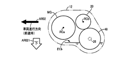
- FIG. 2 is a schematic side view showing the positions of the respective axes when the vehicle drive device of FIG. 1 is viewed from the second speed changer side in the direction of the first axis as indicated by an arrow AR01 in FIG. It is a figure showing the whole vehicle seen from the vehicle upper side, Comprising: It is a figure for demonstrating the positional relationship of the drive device for vehicles of FIG. 1, and the driver's seat of a vehicle.
- FIG. 4 is a schematic diagram for explaining a vehicle drive device according to a second embodiment.
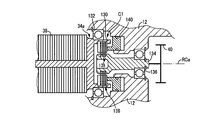
- FIG. 5 is a cross-sectional view showing a portion including a first clutch, that is, a portion surrounded by a one-dot chain line A01 in FIG. 4 in the vehicle drive device of FIG.
- FIG. 6 is a schematic diagram for explaining a vehicle drive device according to a third embodiment.
- FIG. 10 is a schematic diagram for explaining a vehicle drive device according to a fourth embodiment. As indicated by an arrow AR07 in FIG. 7, a schematic side surface showing each axial position when the vehicle drive device in FIG. 7 is viewed from the second clutch side toward the first clutch in the direction of the first axial center.
- FIG. It is an image figure showing the state by which the drive device for conventional electric vehicles was mounted in the vehicle.
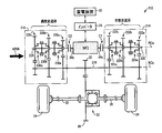
- FIG. 1 is a skeleton diagram for explaining a vehicle drive device 10 to which the present invention is applied.
- the first axis RCa is the rotation axis of the electric motor MG
- the second axis RCb is the rotation axis of the counter shaft 18.
- the first shaft center RCa, the second shaft center RCb, and the shaft center of the drive axle 26 are not on one plane, but in FIG. 1, the first shaft center RCa, The second shaft center RCb and the shaft center of the drive axle 26 are shown in a flat plane.
- the vehicle drive device 10 includes a transaxle case (T / A case) 12 (hereinafter referred to as “case 12”) as a non-rotating member attached to the vehicle body by bolting or the like.
- case 12 which is a housing of the vehicle drive device 10
- the electric motor MG, the first transmission unit 14, the second transmission unit 16, the first clutch C1, the second clutch C2, the counter shaft 18, the intermediate gear 20, and the differential A gear device (differential gear) 22 is provided.
- the first axis RCa, the second axis RCb, and the rotational axis of the differential gear device 22 are parallel to each other.
- the vehicle drive device 10 is suitably placed in front of a front-wheel drive vehicle 8 (see FIG. 3) in which a driving force source for driving is arranged in front of the vehicle, for example, to drive the drive wheels 24. It is used.
- a driving force source for driving is arranged in front of the vehicle, for example, to drive the drive wheels 24. It is used.
- the first clutch C1 and the second clutch C2 are alternatively engaged, for example, the first clutch C1 is engaged.
- the second clutch C2 is released, the power of the electric motor MG is supplied from the output rotating member 34 of the electric motor MG to the first transmission unit 14, the first clutch C1, the intermediate gear 20, and the differential gear device 22.
- the electric motor MG is a so-called motor generator that has a first axial center RCa as a rotational axis and has a power generation function as well as a motor function that outputs vehicle driving power to the drive wheels 24.
- the motor MG is a three-phase synchronous motor generator, which is fixed to the inside of the case 12 by bolting or the like and has a three-phase coil, and is provided on the inner peripheral side of the motor stator 36.
- An output rotating member 34 that is an electric motor output shaft that can rotate around the first axis RCa with respect to the cage motor stator 36, and a permanent magnet that is provided on the inner peripheral side of the electric motor stator 36 and is fixed to the outer periphery of the output rotating member 34.
- the electric motor rotor 38 having The electric motor MG is electrically connected to the power storage device 30 via the inverter 28, and the electric motor MG and the power storage device 30 are configured to be able to exchange power with each other.
- the power storage device 30 is, for example, a battery (secondary battery) such as a lead storage battery or a capacitor, and is an electrical energy source that can supply power to the motor MG and receive power from the motor MG. .
- the output rotating member 34 of the electric motor MG protrudes on both sides of the electric motor MG in the direction along the first axis RCa, and the power of the electric motor MG is output from one end and the other end of the output rotating member 34.
- One end portion of the output rotating member 34 constitutes a first output shaft 34a that outputs the power of the electric motor MG to the first transmission unit 14, and the other end portion of the output rotating member 34 supplies the power of the electric motor MG to the second.
- a second output shaft 34b that outputs to the transmission unit 16 is configured. That is, the first output shaft 34a and the second output shaft 34b rotate integrally around the first axis RCa.
- the first transmission unit 14 is disposed on the first output shaft 34a side with respect to the electric motor MG, and has a first input side gear 40 rotatable around the first axis RCa and around the second axis RCb. And a rotatable first output gear 42.
- the first input side gear 40 and the first output side gear 42 are meshed with each other to form a pair of gears (gear pair).
- the first input side gear 40 is connected in series to the first output shaft 34a on the first axis RCa.
- the second transmission unit 16 is disposed on the second output shaft 34b side with respect to the electric motor MG, and has a second input side gear 44 that can rotate around the first axis RCa and a second axis RCb. And a rotatable second output side gear 46.
- the second input side gear 44 and the second output side gear 46 are meshed with each other to form one set of gear pairs.
- the second input side gear 44 is connected in series to the second output shaft 34b on the first axis RCa.
- the number of teeth of 44 and the number of teeth of the second output side gear 46 can be calculated.
- the first input side gear 40, the output rotating member 34, and the second input side gear 44 are connected in series from the first transmission unit 14 side, and the first input side gear 40 and the output rotating member 34 are connected.
- the second input side gear 44 are non-rotatable about the first axis RCa and supported by the case 12 so as to be integrally rotatable.
- the intermediate gear 20 is fixed to the counter shaft 18 and is supported with respect to the case 12 so as to be rotatable around the second axis RCb together with the counter shaft 18.
- the counter shaft 18 and the intermediate gear 20 are disposed between the first output side gear 42 and the second output side gear 46 on the second axis RCb.
- the intermediate gear 20 meshes with the diff ring gear 48 of the differential gear device 22, and the motive power input from the electric motor MG to the counter shaft 18 via the first transmission unit 14 or the second transmission unit 16 is driven wheels 24. Output to.
- the first clutch C1 and the second clutch C2 are wet multi-plate hydraulic friction engagement devices in which a plurality of friction plates stacked on each other are pressed by a hydraulic actuator, and are engaged or released by hydraulic control.
- the first clutch C1 and the second clutch C2 can transmit power when they are engaged, and block power transmission when they are released. Moreover, the torque capacity which can be transmitted can be adjusted by making it slip.
- the first clutch C1 is interposed between the first output side gear 42 and the counter shaft 18 on the second axis RCb, and selectively connects the first output side gear 42 and the counter shaft 18 to each other.
- Link. That is, the first clutch C ⁇ b> 1 is a first power connection / disconnection device that can disconnect the first output shaft 34 a from the drive wheels 24 in the power transmission path from the first output shaft 34 a to the drive wheels 24 of the electric motor MG. Function.
- the first output shaft 34a which is one end portion of the output rotation member 34, is connected to the drive wheel 24 by the first clutch C1 so as to be separable.
- the second clutch C2 is interposed between the second output side gear 46 and the counter shaft 18 on the second axis RCb, and the second output side gear 46 and the counter shaft 18 are connected to each other.
- the second clutch C2 is a second power connection / disconnection device that can disconnect the second output shaft 34b from the drive wheels 24 in the power transmission path from the second output shaft 34b to the drive wheels 24 of the electric motor MG. Function.
- the second output shaft 34b which is the other end of the output rotating member 34, is connected to the driving wheel 24 by the second clutch C2 so as to be separable.
- the first output gear 42, the first clutch C1, the intermediate gear 20, the second clutch C2, and the second clutch are arranged from the first transmission 14 side.
- the output side gear 46 is connected in series.
- the differential gear device 22 is connected to a pair of drive wheels 24 via a pair of drive axles 26, and distributes the power of the electric motor MG input to the differential ring gear 48 to each of the pair of drive wheels 24. Then communicate. When a difference in rotation occurs between the pair of drive wheels 24, the differential gear device 22 transmits power while allowing the difference in rotation. As shown in FIG. 1, the differential gear device 22 is preferably disposed at the center between the pair of drive wheels 24.
- the first transmission unit 14, the second transmission unit 16, the first clutch C 1, and the second clutch C 2 as a whole are shifted with the Lo gear that has the transmission ratio ⁇ a. It functions as a two-speed transmission that switches between the Hi gear having the ratio ⁇ b. For example, when the first clutch C1 is engaged and the second clutch C2 is released, the transmission gear ratio of the transmission is switched to the transmission ratio ⁇ a, the first clutch C1 is released, and the second clutch C2 is engaged. If they are combined, the gear ratio of the transmission is switched to the gear ratio ⁇ b.
- the vehicle drive device 10 selectively uses one end (the first output shaft 34a) and the other end (the second output shaft 34b) of the output rotation member 34 by the first clutch C1 and the second clutch C2.
- the speed is changed between the electric motor MG and the driving wheel 24.
- the gear ratio ⁇ a of the first transmission unit 14 is larger than the gear ratio ⁇ b of the second transmission unit 16
- the gear ratio in the transmission between the electric motor MG and the drive wheels 24 is one end of the output rotation member 34. Is connected to the drive wheel 24 while the other end of the output rotating member 34 is disconnected from the drive wheel 24, that is, the first clutch C1 is engaged and the second clutch C2 is released. If it is, it becomes the largest.
- the vehicle drive device 10 is in a power transmission cut-off state in which the power transmission path from the electric motor MG to the drive wheels 24 is cut off by releasing both the first clutch C1 and the second clutch C2.
- both the first clutch C1 and the second clutch C2 are engaged, the rotation of the intermediate gear 20 is prevented even when the electric motor MG is not energized and is idling, so that the drive wheel 24 is It is locked and can exhibit a hill hold function that prevents the vehicle 8 from moving backward on an uphill road, for example. If the hill hold function is exhibited by the engagement of the first clutch C1 and the second clutch C2, the first clutch C1 and the second clutch C2 are normally closed (normally engaged) when the hydraulic pressure is not applied. Close) type is preferred.
- FIG. 2 is a schematic side view showing the positions of the respective axes when the vehicle drive device 10 is viewed from the second transmission unit 16 in the direction of the first axis RCa, as indicated by an arrow AR01 in FIG. is there.
- An arrow AR02 shown in FIG. 2 indicates a vehicle traveling direction when the vehicle 8 moves forward, and an arrow AR021 indicates a downward direction of the vehicle 8.
- the electric motor MG is disposed in front of the vehicle 8 with respect to the differential gear device 22.
- oil (lubricating oil) for lubricating the inside of the vehicle drive device 10 is collected at the bottom of the case 12, and a part of the differential gear device 22 is accumulated in the oil collected at the bottom of the case 12. Soaked.
- oil lubricating oil
- the electric motor MG is provided so as to overlap the differential gear device 22 in the direction of the arrow AR02, that is, in the vehicle traveling direction when the vehicle moves forward. As shown in FIG. 1, the electric motor MG is provided so as to overlap the differential gear device 22 in a direction orthogonal to the rotational axis of the differential gear device 22 (in the direction of arrow AR03 in FIG. 1).
- FIG. 3 is a diagram showing the entire vehicle 8 as viewed from the upper side of the vehicle 8, and is a diagram for explaining the positional relationship between the vehicle drive device 10 and the driver seat 50 of the vehicle 8.
- An arrow AR04 shown in FIG. 3 represents the vehicle traveling direction when the vehicle 8 moves forward.
- the driver seat 50 is a seat that is provided in the passenger compartment and is seated when the driver drives the vehicle 8. Therefore, the position of the driver seat 50 indicates the position of the driver who is traveling the vehicle.
- the driver's seat 50 is provided closer to the second transmission unit 16 than the first transmission unit 14. That is, the driver's seat 50 is provided closer to the other end portion (second output shaft 34b) than one end portion (first output shaft 34a) of the output rotation member 34.
- the output rotation member 34 of the electric motor MG includes the first output shaft 34 a that is one end portion of the output rotation member 34 and the second output shaft that is the other end portion of the output rotation member 34. Power is output from 34b.
- the first output shaft 34a and the second output shaft 34b are connected to the drive wheel 24 so as to be separable. Further, the first output shaft 34 a and the second output shaft 34 b are alternatively connected to the drive wheels 24, thereby shifting between the electric motor MG and the drive wheels 24.
- the power of the motor MG is selectively output from either the first output shaft 34a or the second output shaft 34b of the motor MG, so that the power transmission for transmitting the power of the motor MG to the drive wheels 24 is performed.
- the disposition position of the device specifically, the disposition position of the transmission composed of the first transmission unit 14, the second transmission unit 16, the first clutch C1, and the second clutch C2, is one of the motors MG.
- the electric motor MG in the vehicle 8 on which the electric motor MG is mounted so that the axial direction (first axial center RCa direction) of the output rotating member 34 is parallel to the width direction of the vehicle 8, the width direction of the vehicle 8 (arrow in FIG. 3). It is also possible to arrange the electric motor MG in the center in the AR05 direction).
- the rotational axis of the differential gear device 22 is parallel to the axial direction of the output rotating member 34 of the electric motor MG, and the electric motor MG
- the gear device 22 is provided so as to overlap the direction orthogonal to the rotational axis of the differential gear device 22 (the direction of the arrow AR03 in FIG. 1).
- a part of the differential gear device 22 is immersed in oil accumulated at the bottom of the case 12. Accordingly, it is easy to supply most of the oil pumped up by the rotation of the differential gear device 22, that is, the rotation of the differential ring gear 48, to the electric motor MG, so that the cooling performance of the electric motor MG can be improved.
- the electric motor MG is disposed in front of the vehicle 8 with respect to the differential gear device 22.
- the vehicle 8 may travel backward, but most vehicle travel is forward travel. Therefore, although the electric motor MG is housed in the case 12 together with the differential gear device 22 and the like, the motor MG has priority over the differential gear device 22 and the like due to air introduced from the front of the vehicle when the vehicle 8 travels forward. It will be cooled down.
- the vehicle drive device 10 of the present embodiment it is possible to increase the cooling performance of the electric motor MG as compared with the case where the electric motor MG is disposed behind the differential gear device 22. is there.
- the speed ratio in the speed change between the electric motor MG and the drive wheel 24 is such that the one end portion of the output rotation member 34 is connected to the drive wheel 24 while the output rotation.
- the driver's seat 50 of the vehicle 8 is provided closer to the other end than the one end of the output rotation member 34. Therefore, in the vehicle drive device 10, the one end side is more in the other side due to the difference in the gear ratio in the shift between the electric motor MG and the drive wheel 24, that is, the difference between the gear ratios ⁇ a and ⁇ b.
- the driver's seat 50 is disposed away from the side on which noise and vibration are likely to increase, thereby suppressing deterioration of driver comfort. Is possible.
- the differential gear device 22 is preferably disposed at the center between the pair of drive wheels 24, and as such If so, the pair of drive axles 26 can be shared as parts.
- FIG. 4 is a skeleton diagram for explaining the vehicle drive device 110 of the present embodiment.
- FIG. 5 is a cross-sectional view showing a portion including the first clutch C1, that is, a portion surrounded by a one-dot chain line A01 in FIG.
- the vehicle drive device 110 of the present embodiment basically has the same configuration as shown in FIG. 1 and FIG. 4, but the arrangement positions of the first clutch C1 and the second clutch C2 are implemented. This is different from the vehicle drive device 10 of Example 1.
- the first clutch C1 included in the vehicle drive device 110 has the same function as the first connecting / disconnecting device as in the first embodiment, but in the vehicle drive device 110, the first clutch C1 includes:
- the first input side gear 40 and the first output shaft 34a of the motor MG are interposed between the first input side gear 40 and the first output shaft 34a on the first axis RCa.
- Link for example, as shown in FIG. 5, the first output shaft 34 a includes a cylindrical portion 130 that opens toward the first input side gear 40 and protrudes from the motor rotor 38 in a cylindrical shape.
- the ball bearing 132 is fitted into the case 12 so as to be rotatable with respect to the case 12.
- the first clutch C1 includes a plurality of outer peripheral friction plates 138 that cannot rotate relative to the cylindrical portion 130 and a plurality of inner peripheral friction plates 139 that cannot rotate relative to the connecting shaft 134 in the first axis RCa direction. It is prepared by alternately overlapping.
- the first clutch C1 is configured such that the hydraulically actuated piston 140 of the first clutch C1 presses the outer peripheral friction plate 138 and the inner peripheral friction plate 139 in the direction of the first axis RCa. A frictional force is generated and engaged between the side friction plate 138 and the inner peripheral friction plate 139.
- the second clutch C2 included in the vehicle drive device 110 has the same function as the second connecting / disconnecting device as in the first embodiment.
- the second clutch C2 includes the second clutch C2.
- the second input side gear 44 and the second output shaft 34b of the electric motor MG are interposed between the second input side gear 44 and the second output shaft 34b on the one axis RCa, and selectively connect the second input side gear 44 and the second output shaft 34b.
- the first output side gear 42, the intermediate gear 20, and the second output side gear 46 are connected in series on the second axis RCb by the counter shaft 18, and the first output side gear 42, the intermediate gear 20 and the second output side gear 46 are connected in series.
- the output side gear 42, the intermediate gear 20, and the second output side gear 46 rotate integrally around the second axis RCb without being separated from each other.
- the second clutch C2 also has the same structure as the first clutch C1 described in FIG.
- the vehicle drive device 110 of the present embodiment has the following effects in addition to the effects (A1) to (A5) of the first embodiment described above.
- the first clutch C ⁇ b> 1 functions as the first power connection / disconnection device capable of disconnecting one end portion (first output shaft 34 a) of the output rotation member 34 from the drive wheel 24.
- the first clutch C ⁇ b> 1 is interposed between the first input side gear 40 and the first output shaft 34 a, and the first input side gear 40 is between the first output shaft 34 a and the drive wheel 24. Is a gear closest to the electric motor MG and constituting a part of the power transmission path.
- the second clutch C ⁇ b> 2 functions as the second power connection / disconnection device capable of separating the other end portion (second output shaft 34 b) of the output rotation member 34 from the drive wheel 24.
- the second clutch C ⁇ b> 2 is interposed between the second input side gear 44 and the second output shaft 34 b, and the second input side gear 44 is between the second output shaft 34 b and the drive wheel 24. Is a gear closest to the electric motor MG and constituting a part of the power transmission path. Therefore, when the first clutch C1 connects the first output shaft 34a to the drive wheel 24, that is, when the first clutch C1 is engaged, the power transmission from the output rotating member 34 of the electric motor MG is the second.
- the second clutch C2 Before the power is transmitted from the output shaft 34b to the second input side gear 44, it is disconnected by the second clutch C2, and conversely, the second clutch C2 connects the second output shaft 34b to the drive wheels 24, that is, When the second clutch C2 is engaged, the power transmission from the output rotating member 34 of the electric motor MG is transmitted by the first clutch C1 before the power is transmitted from the first output shaft 34a to the first input side gear 40. Since it is cut off, for example, even if there is a torque fluctuation of the electric motor MG, it is possible to reduce the rattling noise that may occur in the gear that is not involved in the power transmission.
- FIG. 6 is a skeleton diagram for explaining the vehicle drive device 210 of the present embodiment.
- the electric motor MG is illustrated in a simplified manner as compared with FIGS. 1 and 4, but the electric motor MG included in the vehicle driving device 210 is the same as the electric motor MG included in the above-described vehicle driving devices 10 and 110. It is.
- each of the first transmission unit 214 and the second transmission unit 216 includes a plurality of shift stages. This is different from the vehicle drive device 110 of Example 2.
- the counter shaft 218 supports the intermediate gear 20 in a relatively non-rotatable manner with the second shaft center RCb as the rotation axis, similarly to the counter shaft 18 of the second embodiment, and together with the intermediate gear 20. It rotates integrally around the second axis RCb.
- FIG. 6 a schematic side view showing each axial position when the vehicle drive device 210 is viewed from the second transmission unit 216 side in the direction of the first axial center RCa. 2 as described in the first embodiment.
- the electric motor MG the first transmission unit 214, the second transmission unit 216, the first clutch C1, the second clutch C2, the counter shaft 218, the intermediate gear 20, the differential gear unit 22, and the like
- the case 12 is housed.
- Each of the first transmission unit 214 and the second transmission unit 216 is a so-called always-meshing parallel shaft type transmission with three-speed transmission, and includes the first transmission unit 214, the second transmission unit 216, the first clutch C1, and the first clutch C1.
- the two-clutch C2 as a whole constitutes a transmission with a total of six gears from the first gear G1 to the sixth gear G6.
- the first transmission unit 214 sets odd-numbered shift stages, which are the first shift stage G1, the third shift stage G3, and the fifth shift stage G5, among the plurality of predetermined shift stages G1 to G6. This is an alternative transmission.
- the second transmission unit 216 alternatively establishes even-numbered shift stages, which are the second shift stage G2, the fourth shift stage G4, and the sixth shift stage G6, among the plurality of shift stages G1 to G6. It is a transmission.
- the first clutch C1 and the second clutch C2 are alternatively engaged when the power of the electric motor MG is transmitted to the drive wheels 24. As a result, any one of the gears G1 to G6 is established.
- the first transmission unit 214 is connected in series to the first output shaft 34a of the electric motor MG via the first clutch C1 and has a first transmission unit input shaft 220 having a first shaft center RCa as a rotation axis, and a first thereof.
- a first gear supported in a relatively rotatable manner on one of the two parallel shafts 218 and 220 (specifically, the first transmission portion input shaft 220), which is the transmission portion input shaft 220 and the counter shaft 218, is parallel to the first gear.
- a plurality of speed change gear pairs (gear pairs) 222a to 222c constituted by a second gear supported on the other of the two shafts 218 and 220 (specifically, counter shaft 218) so as not to rotate relative to each other, and their speed changes
- a plurality of synchromesh type synchronous mesh clutches (synchronous meshing devices) 224a for selectively coupling the synchronized side gears of the gear pairs 222a to 222c, that is, the first gear to the one of the two parallel shafts 218, 220.
- the counter shaft 218 has a function as a first transmission unit output shaft that outputs power from the first transmission unit 214 toward the drive wheels 24.
- the synchronous mesh clutches 224a to 224c are operated to selectively connect the first gears constituting the transmission gear pairs 222a to 222c to the first transmission unit input shaft 220 so as not to be relatively rotatable.
- the 1-speed changer input shaft 220 and the plurality of first gears are operated so as not to be connected to each other so as not to be relatively rotatable.
- the plurality of transmission gear pairs 222a to 222c can alternatively transmit power in the first transmission unit 214, and the first clutch C1 is engaged and the second clutch C2 is engaged.
- any one of the odd speed stages G1, G3, G5 is established.
- the synchronized side gear (first gear) of the transmission gear pair 222a and the first transmission unit input shaft 220 are connected to each other by a synchronous meshing clutch 224a so as not to be relatively rotatable, and the first clutch C1 is engaged.
- the second clutch C2 is released, the first gear stage G1 is established.
- the synchronized side gear of the transmission gear pair 222b and the first transmission portion input shaft 220 are connected to each other by a synchronous meshing clutch 224b so as not to be relatively rotatable, and the first clutch C1 is engaged and the second clutch C2 is engaged. Is released, the third gear stage G3 is established. Further, the synchronized side gear of the transmission gear pair 222c and the first transmission portion input shaft 220 are connected so as not to be relatively rotatable by the synchronous meshing clutch 224c, and the first clutch C1 is engaged and the second clutch C2 is engaged. Is released, the fifth shift stage G5 is established.
- the second transmission unit 216 is connected in series to the second output shaft 34b of the electric motor MG via the second clutch C2, and has a second transmission unit input shaft 226 having the first axis RCa as the rotation axis, and a second thereof.
- a first gear supported in a relatively rotatable manner on one of the two parallel shafts 218 and 226 (specifically, the second transmission portion input shaft 226), which is the transmission portion input shaft 226 and the counter shaft 218, is parallel to the first gear.
- a plurality of speed change gear pairs (gear pairs) 228a to 228c composed of a second gear supported on the other of the two shafts 218 and 226 (specifically, counter shaft 218) so as not to rotate relative to each other, and their speed changes
- the counter shaft 218 has a function as a second transmission unit output shaft that outputs power from the second transmission unit 216 toward the drive wheels 24.
- the synchronous mesh clutches 230a to 230c are operated so as to selectively connect the first gears constituting the transmission gear pairs 228a to 228c to the second transmission unit input shaft 226 so as not to be relatively rotatable.
- the two-transmission unit input shaft 226 and the plurality of first gears are operated so as not to be connected to each other so as not to be relatively rotatable.
- the plurality of transmission gear pairs 228a to 228c can alternatively transmit power in the second transmission unit 216, and the first clutch C1 is released and the second clutch C2 is engaged.
- any one of the even speed stages G2, G4, G6 is established.
- the synchronized side gear (first gear) of the transmission gear pair 228a and the second transmission portion input shaft 226 are connected to each other so as not to rotate relative to each other by the synchronous meshing clutch 230a, and the first clutch C1 is released.
- the second clutch C2 is engaged, the second gear stage G2 is established.
- the synchronized side gear of the transmission gear pair 228b and the second transmission portion input shaft 226 are connected to each other by a synchronous meshing clutch 230b so as not to be relatively rotatable, and the first clutch C1 is released and the second clutch C2 is connected.
- the fourth shift stage G4 is established.
- the synchronized side gear of the transmission gear pair 228c and the second transmission portion input shaft 226 are connected to each other by a synchronous meshing clutch 230c so as not to be relatively rotatable, and the first clutch C1 is released and the second clutch C2 is connected.
- the sixth shift stage G6 is established.
- the gear ratios of the transmission gear pairs 222a to 222c and 228a to 228c are different from each other, and are determined corresponding to the transmission ratio ⁇ 1 to the transmission ratio ⁇ 6.
- a shift in the vehicle drive device 210 that is, a shift between the electric motor MG and the drive wheel 24 is performed between the first clutch C1 and the second clutch C2. It is done by holding. Specifically, when one of the first clutch C1 and the second clutch C2 is engaged and the power of the electric motor MG is transmitted to the drive wheels 24 and the vehicle is traveling, the one-stage shift is performed. The one of the first clutch C1 and the second clutch C2 is released and the other is engaged. Therefore, in this case, one transmission gear pair 222a that establishes the gear stage after the shift in the first transmission unit 214 or the second transmission unit 216 connected to the other first clutch C1 or the second clutch C2.
- ⁇ 222c and 228a ⁇ 228c can transmit power, and thereafter, the first clutch C1 and the second clutch C2 are replaced.
- the synchronized side gear of the speed change gear pair 228b and the second speed changer input shaft 226 while the second clutch C2 is released. Are coupled by the synchronous mesh clutch 230b so as not to be relatively rotatable, and thereafter, the first clutch C1 is released and the second clutch C2 is engaged.
- the vehicle drive device 210 of the present embodiment has the following effects in addition to the effects of the second embodiment described above.
- the gear shift between the electric motor MG and the drive wheels 24 is to select one gear from a plurality of predetermined gears G1 to G6.
- the first transmission portion 214 that establishes the odd-numbered shift stages G1, G3, and G5 among the plurality of shift stages G1 to G6 and one end portion (first output shaft 34a) of the output rotation member 34 are used as the drive wheels 24.
- a first clutch C1 that can be disconnected is connected in series to form a part of a power transmission path between the first output shaft 34a and the drive wheels 24.
- the second transmission portion 216 that establishes the even-numbered shift stages G2, G4, G6 among the plurality of shift stages G1 to G6 and the other end portion (second output shaft 34b) of the output rotating member 34 are driven wheels.
- a second clutch C ⁇ b> 2 that can be disconnected with respect to 24 is connected in series to constitute a part of a power transmission path between the second output shaft 34 b and the drive wheel 24. Accordingly, for example, the first clutch C1 and the second clutch C2 are compared with the case where the first transmission unit 214 and the second transmission unit 216 are disposed only on one end side or the other end side of the output rotation member 34, for example. It becomes easy to arrange
- FIG. 7 is a skeleton diagram for explaining the vehicle drive device 310 of the present embodiment.
- the electric motor MG is illustrated in a simplified manner as compared with FIGS. 1 and 4, but the electric motor MG included in the vehicle drive device 310 is the vehicle drive device 10 or 110 described above.
- 210 is the same as the motor MG.
- the vehicle drive device 310 according to the present embodiment as can be seen by comparing FIG. 7 and FIG.
- the number of shift stages of the second transmission unit 316 is different from that of the vehicle drive device 210 of the third embodiment.
- the first axis RC1 is the rotation axis of the electric motor MG
- the second axis RC2 is the rotation axis of the counter shaft 318
- the third axis RC3 is the rotation of the first transmission unit input shaft 320.
- the fourth axial center RC4 is the rotational axis of the second transmission unit input shaft 326.
- the first axis RC1, the second axis RC2, the third axis RC3, the fourth axis RC4, and the rotation axis of the differential gear device 22 are parallel to each other.
- the counter shaft 318 and the gear supported by the counter shaft 318 are illustrated in a portion surrounded by a broken line L01 and a portion surrounded by a broken line L02, respectively.
- the portions surrounded by the broken line L02 are not illustrated as being provided in pairs, but are virtually illustrated to show the transmission gear pairs 328a and 328b included in the second transmission unit 316 in an easily understandable manner.
- the counter shaft 318 supports the intermediate gear 20 in a relatively non-rotatable manner with the second shaft center RC ⁇ b> 2 serving as the rotational axis, similarly to the counter shaft 218 of the third embodiment described above. It rotates integrally around the second axis RC2.
- Each of the first transmission unit 314 and the second transmission unit 316 is a so-called always-meshing parallel shaft type transmission with two-stage transmission, and includes the first transmission unit 314, the second transmission unit 316, the first clutch C1, and the first clutch C1.
- the two-clutch C2 as a whole constitutes a transmission with a total of four speeds from the first speed G01 to the fourth speed G04.
- the first transmission unit 314 alternatively establishes odd-numbered shift stages that are the first shift stage G01 and the third shift stage G03 among the plurality of predetermined shift stages G01 to G04. It is a transmission.
- the second transmission unit 316 is a transmission that alternatively establishes an even-numbered shift stage that is the second shift stage G02 and the fourth shift stage G04 among the plurality of shift stages G01 to G04.
- the first clutch C1 and the second clutch C2 are alternatively engaged when the power of the electric motor MG is transmitted to the drive wheels 24, as in the third embodiment. Any one of the above-described gear stages G01 to G04 is established.
- the first transmission unit 314 is connected in series to the first output shaft 34a of the electric motor MG via the first clutch C1, and has a first drive side input gear 319a having the first shaft center RC1 as a rotation axis, and a first thereof.
- the first driven side input gear 319b meshing with the driving side input gear 319a and having the third axis RC3 as the rotational axis, and the first driven side input gear 319b and the first driven side input gear 319b are connected so as not to rotate relative to each other.
- the first gear is supported on the input shaft 320 so as to be relatively rotatable
- the second gear is supported on the other of the two parallel shafts 318 and 320 (specifically, the counter shaft 318) so as not to be relatively rotatable.
- the counter shaft 318 has a function as a first transmission unit output shaft that outputs power from the first transmission unit 314 toward the drive wheels 24 as in the third embodiment.
- the synchronous mesh clutches 324a and 324b are operated to selectively connect the first gears constituting the transmission gear pairs 322a and 322b to the first transmission unit input shaft 320 so as not to rotate relative thereto.
- the first transmission unit input shaft 320 and the plurality of first gears are operated so as not to be connected to each other so as not to be relatively rotatable.
- the plurality of transmission gear pairs 322a and 322b can alternatively transmit power in the first transmission unit 314, and the first clutch C1 is engaged and the second clutch C2 is engaged.
- the first clutch C1 is engaged and the second clutch C2 is engaged.
- the synchronized side gear (first gear) of the transmission gear pair 322a and the first transmission unit input shaft 320 are connected to each other so as not to rotate relative to each other by the synchronous meshing clutch 324a, and the first clutch C1 is engaged.
- the second clutch C2 is released, the first gear stage G01 is established.
- the synchronized side gear of the transmission gear pair 322b and the first transmission unit input shaft 320 are connected to each other by a synchronous meshing clutch 324b so as not to be relatively rotatable, and the first clutch C1 is engaged and the second clutch C2 is engaged. Is released, the third shift stage G03 is established.
- the second transmission unit 216 is connected in series to the second output shaft 34b of the electric motor MG via the second clutch C2, and has a second drive side input gear 325a having the first shaft center RC1 as the rotation axis, A second driven input gear 325b that meshes with the driving side input gear 325a and has a fourth axis RC4 as a rotation axis, and a fourth axis that is connected to the second driven side input gear 325b so as not to be relatively rotatable.
- the first gear is supported on the input shaft 326 so as to be relatively rotatable
- the second gear is supported on the other of the two parallel shafts 318 and 326 (specifically, the counter shaft 318) so as not to be relatively rotatable.
- the counter shaft 318 has a function as a second transmission unit output shaft that outputs power from the second transmission unit 316 toward the drive wheels 24, as in the third embodiment.
- the synchronous mesh clutches 330a and 330b are operated to selectively connect the first gear constituting the transmission gear pair 328a and 328b to the second transmission unit input shaft 326 so as not to be relatively rotatable.
- the second transmission unit input shaft 326 and the plurality of first gears are operated so as not to be connected to each other so as not to be relatively rotatable.
- the plurality of transmission gear pairs 328a and 328b can alternatively transmit power in the second transmission unit 316, and the first clutch C1 is released and the second clutch C2 is engaged.
- one of the even speed stages G02 and G04 is established.
- the synchronized side gear (first gear) of the transmission gear pair 328a and the second transmission unit input shaft 326 are connected to each other so as not to rotate relative to each other by the synchronous mesh clutch 330a, and the first clutch C1 is released.
- the second clutch C2 is engaged, the second gear stage G02 is established.
- the synchronized side gear of the transmission gear pair 328b and the second transmission portion input shaft 326 are connected to each other so as not to rotate relative to each other by the synchronous mesh clutch 330b, and the first clutch C1 is released and the second clutch C2 is connected. By engaging, the fourth gear stage G04 is established. Note that the gear ratios of the transmission gear pairs 322a, 322b, 328a, and 328b are different from each other, and are determined corresponding to the transmission ratio ⁇ 01 to the transmission ratio ⁇ 04.
- the shift in the vehicle drive device 310 that is, the shift between the electric motor MG and the drive wheels 24, is the same as that of the vehicle drive device 210 of the third embodiment.
- the first clutch C1 and the second clutch C2 are replaced with each other.
- FIG. 8 shows each axial position when the vehicle drive device 310 is viewed from the second clutch C2 side toward the first clutch C1 in the direction of the first axial center RC1, as indicated by an arrow AR07 in FIG. FIG.
- An arrow AR08 shown in FIG. 8 indicates a vehicle traveling direction when the vehicle 308 moves forward, and an arrow AR081 indicates a downward direction of the vehicle 308.
- the electric motor MG is disposed in front of the vehicle 308 with respect to the differential gear device 22, similarly to the vehicle drive device 10 of FIG. 2. Further, oil (lubricating oil) for lubricating the inside of the vehicle drive device 310 is accumulated at the bottom of the case 12, and a part of the differential gear device 22 is accumulated in the oil accumulated at the bottom of the case 12. Soaked.
- the vehicle drive device 310 is housed in the case 12. Further, as shown in FIG. 8, in the vehicle drive device 310, the third axis RC3 is provided below the vehicle 308 than the fourth axis RC4. That is, the first transmission unit 314 is disposed below the vehicle 308 with respect to the second transmission unit 316.
- the transmission gear pair 322a, 322b of the first transmission unit 314 is disposed on the electric motor MG side with respect to the first driven input gear 319b in the direction of the third axis RC3.
- the first transmission unit 314 is provided so as to overlap the electric motor MG in a direction orthogonal to the rotation axis of the differential gear device 22. More specifically, some or all of the plurality of transmission gear pairs 322a and 322b included in the first transmission unit 314 overlap with the electric motor MG in a direction orthogonal to the rotational axis of the differential gear device 22. Is provided. Further, the same applies to the second transmission unit 316.
- the transmission gear pair 328a, 328b of the second transmission unit 316 is arranged on the motor MG side with respect to the second driven input gear 325b in the direction of the fourth axis RC4. It is installed. That is, the second transmission unit 316 is provided so as to overlap the electric motor MG in a direction orthogonal to the rotational axis of the differential gear device 22. Specifically, a part or all of the plurality of transmission gear pairs 328a and 328b included in the second transmission unit 316 overlaps the electric motor MG in a direction orthogonal to the rotational axis of the differential gear device 22. Is provided.
- the vehicle drive device 310 of the present embodiment has the following effects in addition to the effects of the third embodiment.
- the electric motor MG, the first transmission unit 314, the second transmission unit 316, and the differential gear device 22 are accommodated in one housing, that is, the case 12, and the first transmission unit 314 is the first transmission unit 314. It is disposed below the vehicle 308 with respect to the second transmission unit 316. Therefore, since the first transmission unit 314 has a lower gear speed stage than the second transmission unit 316, the first transmission unit 314 is more likely to generate heat than the second transmission unit 316, but is swept up by the rotation of the differential gear unit 22. Since more oil is more easily supplied to the first transmission unit 314 than to the second transmission unit 316, the cooling performance of the first transmission unit 314 can be increased.
- the first transmission unit 314 is provided so as to overlap with the electric motor MG in a direction orthogonal to the rotational axis of the differential gear device 22, and the second transmission unit 316 includes the electric motor MG. It is provided so as to overlap MG in a direction orthogonal to the rotational axis of the differential gear device 22. Therefore, it is possible to reduce the size of the vehicle drive device 310 in the direction of the rotational axis of the differential gear device 22. For example, it is easy to reduce the size of the vehicle drive device 310 by increasing the number of shift stages in the vehicle drive device 310.
- the first clutch C1 and the second clutch C2 are wet multi-plate hydraulic friction engagement devices, but may be any power connection / disconnection device capable of connecting / disconnecting power transmission.
- the operation type is not particularly limited, and may be a dry clutch, or may be a magnetic powder type, electromagnetic type, mechanical type engagement device such as a powder (magnetic powder) clutch, an electromagnetic clutch, and a meshing type dog clutch.
- a part of the differential gear device 22 is immersed in the oil accumulated at the bottom of the case 12, but the entire differential gear device 22 is immersed in the oil. It can be done.
- the driver seat 50 is provided closer to the second transmission portion 16 than the first transmission portion 14, but the arrangement of the driver seat 50 is not limited.
- the driver's seat 50 may be disposed closer to the first transmission unit 14 or may be disposed in the center of the vehicle 8 in the width direction.
- the vehicles 8 and 308 are front wheel drive vehicles, but may be rear wheel drive vehicles or four wheel drive vehicles.
- the vehicle drive devices 10, 110, 210, and 310 are mounted on the front side of the vehicle.
- the mounting positions on the vehicles 8 and 308 are not limited, and may be mounted on the rear side or the center of the vehicle, for example. Absent.
- the electric motor MG, the first clutch C1, and the second clutch C2 are components of the vehicle drive devices 110, 210, and 310 that are mechanically independent of each other. Thus, it is not necessary for each of them to be mechanically independent.
- the electric motor MG, the first clutch C1, and the second clutch C2 may constitute one device including those functions.
- the first transmission units 214 and 314 and the second transmission units 216 and 316 have the same number of shift stages, but the first transmission units 214 and 314 have the same speed.
- the number of gears may be less than or greater than the number of gears that the second transmission unit 216, 316 has.
- the first transmission units 214 and 314 and the second transmission units 216 and 316 transmit power by the gear pairs (gear pairs) included in the first transmission units 214 and 314.
- gear pairs gear pairs included in the first transmission units 214 and 314.
- one or more planetary gear devices for establishing each gear position may be provided.
- the vehicle drive devices 10, 110, 210, and 310 are mounted on an electric vehicle.
- a driving force source for traveling may be provided in addition to the electric motor MG.
- the vehicle drive devices 10, 110, 210, and 310 may be mounted on a hybrid vehicle. If it demonstrates using FIG. 3, although the driving wheel 24 is a front wheel, it means that the rear wheel of the vehicle 8 may be driven by other driving force sources, such as an engine.
- the synchronous mesh clutches 224a to 224c, 324a, and 324b of the first transmission units 214 and 314 can also function as the first clutch C1
- the vehicle drive devices 210 and 310 include the first clutch C1 and the first clutch C1.
- One or both of the two clutches C2 may not be provided.
Landscapes
- Engineering & Computer Science (AREA)
- Mechanical Engineering (AREA)
- Transportation (AREA)
- General Engineering & Computer Science (AREA)
- Chemical & Material Sciences (AREA)
- Combustion & Propulsion (AREA)
- Power Engineering (AREA)
- Electric Propulsion And Braking For Vehicles (AREA)
- Hybrid Electric Vehicles (AREA)
- Arrangement Of Transmissions (AREA)
- Connection Of Motors, Electrical Generators, Mechanical Devices, And The Like (AREA)
Abstract
Description
10,110,210,310:車両用駆動装置
14,214,314:第1変速部
16,216,316:第2変速部
22:差動歯車装置
24:駆動輪
26:駆動車軸
34:出力回転部材
34a:第1出力軸(出力回転部材の一端部)
34b:第2出力軸(出力回転部材の他端部)
40:第1入力側歯車(歯車)
44:第2入力側歯車(歯車)
50:運転席
MG:電動機
C1:第1クラッチ(第1動力断接装置)
C2:第2クラッチ(第2動力断接装置)
Claims (6)
- 駆動輪に動力を出力する電動機を備えた車両用駆動装置であって、
該電動機の出力回転部材は該出力回転部材の一端部および他端部から動力を出力し、
該出力回転部材の一端部および他端部はそれぞれ、前記駆動輪と切離し可能に連結されており、
該出力回転部材の一端部と他端部とを択一的に該駆動輪と連結することで、前記電動機と前記駆動輪との間で変速する
ことを特徴とする車両用駆動装置。 - 前記電動機の動力を前記駆動輪に伝達し該電動機の出力回転部材の軸方向と平行な回転軸心を有する差動歯車装置を備え、
前記電動機は、該差動歯車装置に対し、該差動歯車装置の回転軸心と直交する方向に重ねて設けられている
ことを特徴とする請求項1に記載の車両用駆動装置。 - 前記電動機は、前記差動歯車装置に対し、車両の前方に配置されている
ことを特徴とする請求項2に記載の車両用駆動装置。 - 前記出力回転部材の一端部を前記駆動輪に対して切離し可能な第1動力断接装置が、該一端部と該駆動輪との間の動力伝達経路において前記電動機に最も近い歯車と、該一端部との間に介装されており、
前記出力回転部材の他端部を前記駆動輪に対して切離し可能な第2動力断接装置が、該他端部と該駆動輪との間の動力伝達経路において前記電動機に最も近い歯車と、該他端部との間に介装されている
ことを特徴とする請求項1から3の何れか1項に記載の車両用駆動装置。 - 前記電動機と前記駆動輪との間での変速は、予め定められた複数の変速段から一の変速段を選択するものであり、
前記予め定められた複数の変速段のうちの奇数変速段を成立させる第1変速部と、前記出力回転部材の一端部を前記駆動輪に対して切離し可能な第1動力断接装置とが直列に連結されて、該出力回転部材の一端部と該駆動輪との間の動力伝達経路の一部を構成しており、
前記予め定められた複数の変速段のうちの偶数変速段を成立させる第2変速部と、前記出力回転部材の他端部を前記駆動輪に対して切離し可能な第2動力断接装置とが直列に連結されて、該出力回転部材の他端部と該駆動輪との間の動力伝達経路の一部を構成している
ことを特徴とする請求項1から4の何れか1項に記載の車両用駆動装置。 - 前記電動機と前記駆動輪との間での変速における変速比は、前記出力回転部材の一端部を該駆動輪に対して連結する一方で該出力回転部材の他端部を該駆動輪に対して切り離した場合に、最も大きくなり、
車両の運転席は、前記出力回転部材の一端部よりも他端部寄りに設けられている
ことを特徴とする請求項1から5の何れか1項に記載の車両用駆動装置。
Priority Applications (5)
| Application Number | Priority Date | Filing Date | Title |
|---|---|---|---|
| CN201180069401.7A CN103442924B (zh) | 2011-03-23 | 2011-03-23 | 车辆用驱动装置 |
| JP2013505737A JP5617996B2 (ja) | 2011-03-23 | 2011-03-23 | 車両用駆動装置 |
| US14/005,290 US8678969B2 (en) | 2011-03-23 | 2011-03-23 | Vehicular drive system |
| PCT/JP2011/057053 WO2012127668A1 (ja) | 2011-03-23 | 2011-03-23 | 車両用駆動装置 |
| DE112011105075.5T DE112011105075B4 (de) | 2011-03-23 | 2011-03-23 | Fahrzeugantriebsvorrichtung |
Applications Claiming Priority (1)
| Application Number | Priority Date | Filing Date | Title |
|---|---|---|---|
| PCT/JP2011/057053 WO2012127668A1 (ja) | 2011-03-23 | 2011-03-23 | 車両用駆動装置 |
Publications (1)
| Publication Number | Publication Date |
|---|---|
| WO2012127668A1 true WO2012127668A1 (ja) | 2012-09-27 |
Family
ID=46878861
Family Applications (1)
| Application Number | Title | Priority Date | Filing Date |
|---|---|---|---|
| PCT/JP2011/057053 Ceased WO2012127668A1 (ja) | 2011-03-23 | 2011-03-23 | 車両用駆動装置 |
Country Status (5)
| Country | Link |
|---|---|
| US (1) | US8678969B2 (ja) |
| JP (1) | JP5617996B2 (ja) |
| CN (1) | CN103442924B (ja) |
| DE (1) | DE112011105075B4 (ja) |
| WO (1) | WO2012127668A1 (ja) |
Cited By (7)
| Publication number | Priority date | Publication date | Assignee | Title |
|---|---|---|---|---|
| CN104295674A (zh) * | 2014-09-15 | 2015-01-21 | 山东理工大学 | 多挡环形布置式线控自动变速器 |
| CN104295677A (zh) * | 2014-09-15 | 2015-01-21 | 山东理工大学 | 双级线控多挡自动变速器 |
| CN104389958A (zh) * | 2014-09-15 | 2015-03-04 | 山东理工大学 | 电动汽车多挡线控自动变速器 |
| JPWO2013128647A1 (ja) * | 2012-03-02 | 2015-07-30 | トヨタ自動車株式会社 | 車両用駆動装置 |
| WO2020067273A1 (ja) * | 2018-09-28 | 2020-04-02 | 日本電産株式会社 | モータユニット |
| JP2023118535A (ja) * | 2022-02-15 | 2023-08-25 | 株式会社小松製作所 | 作業機械 |
| WO2026053418A1 (ja) * | 2024-09-09 | 2026-03-12 | 日産自動車株式会社 | 電動駆動装置及び電動駆動装置を備える車両 |
Families Citing this family (36)
| Publication number | Priority date | Publication date | Assignee | Title |
|---|---|---|---|---|
| WO2014057514A1 (ja) * | 2012-10-10 | 2014-04-17 | 川崎重工業株式会社 | 電動車両 |
| WO2015149874A1 (de) * | 2014-04-04 | 2015-10-08 | Gkn Driveline International Gmbh | Antriebsanordnung für ein kraftfahrzeug |
| DE102014213010A1 (de) | 2014-07-04 | 2016-01-07 | Zf Friedrichshafen Ag | Getriebe für den Antriebsstrang eines Schienenfahrzeugs |
| DE102014109776A1 (de) * | 2014-07-11 | 2016-01-14 | Dr. Ing. H.C. F. Porsche Aktiengesellschaft | Elektrisch angetriebene Achse in einem Kraftfahrzeug |
| FR3053007B1 (fr) * | 2016-06-28 | 2019-08-23 | France Reducteurs | Transmission, notamment pour engin roulant, et engin roulant equipe d'une telle transmission |
| CN106218383A (zh) * | 2016-07-21 | 2016-12-14 | 北京新能源汽车股份有限公司 | 汽车及其传动系统 |
| CN206277947U (zh) * | 2016-09-28 | 2017-06-27 | 精进电动科技股份有限公司 | 一种车辆电驱动总成 |
| CN106696691B (zh) * | 2016-11-18 | 2019-02-15 | 精进电动科技股份有限公司 | 一种横置单动力源车辆驱动总成 |
| EP3354920B1 (de) * | 2017-01-31 | 2019-12-11 | GKN Driveline Bruneck AG | Kupplungsanordnung für einen antriebsstrang und getriebeanordnung mit einer solchen kupplungsanordnung |
| FR3067972B1 (fr) * | 2017-06-23 | 2020-01-03 | Lohr Industrie | Mecanique centrale pour essieu motorise de vehicule |
| US10851881B2 (en) * | 2017-09-08 | 2020-12-01 | Guangzhou Sunmile Dynamic Technologies Corp., Ltd | Four-speed transaxle for electric vehicle |
| WO2019152065A1 (en) * | 2018-02-02 | 2019-08-08 | Dana Automotive Systems Group, Llc | Electric drive axle with multi-speed gearbox |
| CN112204271B (zh) * | 2018-06-02 | 2023-09-26 | 有能沛思株式会社 | 电动汽车用二级变速器 |
| FR3084621B1 (fr) * | 2018-08-03 | 2021-09-10 | Valeo Embrayages | Systeme de propulsion pour vehicule electrique |
| CN212685116U (zh) * | 2018-09-25 | 2021-03-12 | 德纳汽车系统集团有限责任公司 | 电驱动桥 |
| FR3092793B1 (fr) * | 2019-02-15 | 2021-01-29 | Valeo Embrayages | Dispositif de transmission de couple pour un véhicule automobile |
| DE102019212145A1 (de) * | 2019-08-13 | 2021-02-18 | Zf Friedrichshafen Ag | Getriebeanordnung, Hybrid-Getriebeanordnung, Hybrid-Antriebsstrang sowie Kraftfahrzeug |
| US11524576B2 (en) | 2019-12-09 | 2022-12-13 | GM Global Technology Operations LLC | Speed reduction assembly and a vehicle that utilizes the speed reduction assembly |
| FR3105815B1 (fr) * | 2019-12-26 | 2022-01-07 | Valeo Embrayages | Groupe motopropulseur Electrique A DEUX EMBRAYAGES |
| FR3105813B1 (fr) * | 2019-12-26 | 2022-04-08 | Valeo Embrayages | Groupe motopropulseur Electrique A DEUX EMBRAYAGES |
| US11148526B2 (en) * | 2020-02-19 | 2021-10-19 | Dana Automotive Systems Group, Llc | Electric drive axle gear train and method for manufacturing said gear train |
| US11235660B2 (en) * | 2020-02-19 | 2022-02-01 | Dana Automotive Systems Group, Llc | Electric drive axle system with multi-speed gear train |
| WO2021171418A1 (ja) * | 2020-02-26 | 2021-09-02 | 株式会社ユニバンス | 動力伝達装置 |
| US11460093B2 (en) | 2020-10-28 | 2022-10-04 | Dana Automotive Systems Group, Llc | Vehicle system with multi-speed transmission |
| DE102021206962A1 (de) | 2021-07-02 | 2023-01-05 | Zf Friedrichshafen Ag | Getriebeanordnung mit zwei Reibkupplungen für ein Fahrzeug sowie Antriebstrang und Fahrzeug mit der Getriebeanordnung |
| DE102021117059B4 (de) * | 2021-07-02 | 2023-03-30 | Audi Aktiengesellschaft | Antriebsvorrichtung für eine elektrifizierte Fahrzeugachse |
| DE102022206880A1 (de) * | 2022-07-06 | 2024-01-11 | Zf Friedrichshafen Ag | Elektrische Antriebsanordnung für ein Fahrzeug |
| DE102022206875A1 (de) * | 2022-07-06 | 2024-01-11 | Zf Friedrichshafen Ag | Elektrische Antriebsanordnung für ein Fahrzeug |
| DE102022119475A1 (de) * | 2022-08-03 | 2024-02-08 | Audi Aktiengesellschaft | Antriebsstrang für ein Fahrzeug |
| JP2024043838A (ja) * | 2022-09-20 | 2024-04-02 | 株式会社エクセディ | 駆動ユニット |
| JP2024151270A (ja) * | 2023-04-11 | 2024-10-24 | 株式会社不二越 | 垂直多関節ロボット |
| CN117301835A (zh) * | 2023-10-08 | 2023-12-29 | 东风汽车集团股份有限公司 | 车辆的分布式驱动系统及驱动总成 |
| CN117284067A (zh) * | 2023-10-08 | 2023-12-26 | 东风汽车集团股份有限公司 | 车辆的分布式驱动系统及驱动总成 |
| CN117284069A (zh) * | 2023-10-08 | 2023-12-26 | 东风汽车集团股份有限公司 | 车辆的分布式驱动系统及驱动总成 |
| CN117301833A (zh) * | 2023-10-08 | 2023-12-29 | 东风汽车集团股份有限公司 | 车辆的驱动系统及驱动总成 |
| CN117301834A (zh) * | 2023-10-08 | 2023-12-29 | 东风汽车集团股份有限公司 | 车辆的驱动系统及驱动总成 |
Citations (5)
| Publication number | Priority date | Publication date | Assignee | Title |
|---|---|---|---|---|
| JPS601069A (ja) * | 1983-06-18 | 1985-01-07 | 三菱電機株式会社 | 電動台車用電動機 |
| JPH06335113A (ja) * | 1993-05-20 | 1994-12-02 | Aisin Seiki Co Ltd | 電気自動車の駆動モータ回転制御方法 |
| JP2000142134A (ja) * | 1998-11-11 | 2000-05-23 | Hino Motors Ltd | ハイブリッド自動車 |
| JP2001004016A (ja) * | 1999-06-17 | 2001-01-09 | Nissan Diesel Motor Co Ltd | 電気駆動車両の動力伝達装置 |
| JP2009045993A (ja) * | 2007-08-17 | 2009-03-05 | Hitachi Ltd | 車両用制御装置および車両用動力伝達装置 |
Family Cites Families (10)
| Publication number | Priority date | Publication date | Assignee | Title |
|---|---|---|---|---|
| DE3542059C1 (de) * | 1985-11-28 | 1987-06-04 | Opel Adam Ag | Kraftfahrzeug mit Hauptantriebsachse und zuschaltbarer Antriebsachse |
| JP3620560B2 (ja) | 1997-04-09 | 2005-02-16 | アイシン・エィ・ダブリュ株式会社 | 電気自動車用駆動装置 |
| AU2003215041A1 (en) * | 2002-01-30 | 2003-09-02 | Michael Frederick Johnson | Electric motor drive assembly and its use in a hybridvehicle |
| US7731614B2 (en) * | 2002-04-29 | 2010-06-08 | Caterpillar Inc. | Method and apparatus for an electric drive differential system |
| JP2004316847A (ja) * | 2003-04-18 | 2004-11-11 | Toyota Industries Corp | ディファレンシャル装置 |
| US7316627B2 (en) * | 2004-08-27 | 2008-01-08 | Arvinmeritor Technology, Llc | Integrated two-speed motor |
| DE102006046419B4 (de) * | 2006-09-22 | 2010-04-01 | Getrag Innovations Gmbh | Elektrische Achsantriebsbaugruppe |
| CN201012738Y (zh) * | 2006-11-01 | 2008-01-30 | 蔡玲民 | 一种电动车电机驱动装置 |
| JP5293273B2 (ja) | 2009-03-02 | 2013-09-18 | 日産自動車株式会社 | 電動車両の回生制御装置 |
| JP5337744B2 (ja) | 2010-03-03 | 2013-11-06 | 本田技研工業株式会社 | 動力伝達装置及びハイブリッド駆動装置 |
-
2011
- 2011-03-23 JP JP2013505737A patent/JP5617996B2/ja not_active Expired - Fee Related
- 2011-03-23 US US14/005,290 patent/US8678969B2/en not_active Expired - Fee Related
- 2011-03-23 DE DE112011105075.5T patent/DE112011105075B4/de not_active Expired - Fee Related
- 2011-03-23 CN CN201180069401.7A patent/CN103442924B/zh not_active Expired - Fee Related
- 2011-03-23 WO PCT/JP2011/057053 patent/WO2012127668A1/ja not_active Ceased
Patent Citations (5)
| Publication number | Priority date | Publication date | Assignee | Title |
|---|---|---|---|---|
| JPS601069A (ja) * | 1983-06-18 | 1985-01-07 | 三菱電機株式会社 | 電動台車用電動機 |
| JPH06335113A (ja) * | 1993-05-20 | 1994-12-02 | Aisin Seiki Co Ltd | 電気自動車の駆動モータ回転制御方法 |
| JP2000142134A (ja) * | 1998-11-11 | 2000-05-23 | Hino Motors Ltd | ハイブリッド自動車 |
| JP2001004016A (ja) * | 1999-06-17 | 2001-01-09 | Nissan Diesel Motor Co Ltd | 電気駆動車両の動力伝達装置 |
| JP2009045993A (ja) * | 2007-08-17 | 2009-03-05 | Hitachi Ltd | 車両用制御装置および車両用動力伝達装置 |
Cited By (9)
| Publication number | Priority date | Publication date | Assignee | Title |
|---|---|---|---|---|
| JPWO2013128647A1 (ja) * | 2012-03-02 | 2015-07-30 | トヨタ自動車株式会社 | 車両用駆動装置 |
| CN104295674A (zh) * | 2014-09-15 | 2015-01-21 | 山东理工大学 | 多挡环形布置式线控自动变速器 |
| CN104295677A (zh) * | 2014-09-15 | 2015-01-21 | 山东理工大学 | 双级线控多挡自动变速器 |
| CN104389958A (zh) * | 2014-09-15 | 2015-03-04 | 山东理工大学 | 电动汽车多挡线控自动变速器 |
| WO2020067273A1 (ja) * | 2018-09-28 | 2020-04-02 | 日本電産株式会社 | モータユニット |
| JPWO2020067273A1 (ja) * | 2018-09-28 | 2021-09-16 | 日本電産株式会社 | モータユニット |
| JP7468349B2 (ja) | 2018-09-28 | 2024-04-16 | ニデック株式会社 | モータユニット |
| JP2023118535A (ja) * | 2022-02-15 | 2023-08-25 | 株式会社小松製作所 | 作業機械 |
| WO2026053418A1 (ja) * | 2024-09-09 | 2026-03-12 | 日産自動車株式会社 | 電動駆動装置及び電動駆動装置を備える車両 |
Also Published As
| Publication number | Publication date |
|---|---|
| CN103442924A (zh) | 2013-12-11 |
| JPWO2012127668A1 (ja) | 2014-07-24 |
| CN103442924B (zh) | 2016-02-03 |
| US20140004987A1 (en) | 2014-01-02 |
| JP5617996B2 (ja) | 2014-11-05 |
| DE112011105075B4 (de) | 2018-11-15 |
| DE112011105075T5 (de) | 2014-01-02 |
| US8678969B2 (en) | 2014-03-25 |
Similar Documents
| Publication | Publication Date | Title |
|---|---|---|
| JP5617996B2 (ja) | 車両用駆動装置 | |
| CN102216649B (zh) | 变速器 | |
| CN103832263B (zh) | 用于车辆的动力传动系统及具有其的车辆 | |
| JP6202256B2 (ja) | 車両のトランスアクスル装置 | |
| JP5821963B2 (ja) | 車両用駆動装置 | |
| EP2857243B1 (en) | Transaxle device | |
| CN102821990B (zh) | 车辆用驱动装置 | |
| CN108136889A (zh) | Cvt差速器 | |
| JP2010162924A (ja) | ハイブリット車両の動力伝達装置 | |
| JP5198348B2 (ja) | ハイブリッド車両用トランスミッション | |
| EP3533645A1 (en) | Power train system and vehicle having same | |
| CN111301176A (zh) | 用于车辆的电气驱动装置 | |
| EP3533647A1 (en) | Power train and vehicle having same | |
| JP2010285062A (ja) | 車両用動力伝達装置 | |
| CN114269584B (zh) | 用于机动车的混合动力传动系 | |
| JP2008256075A (ja) | 動力伝達装置 | |
| JP2011025911A (ja) | ハイブリッド車両用自動変速機 | |
| CN113490610A (zh) | 变速器组件、机动车辆动力传动系及对其操作的方法 | |
| EP3533648A1 (en) | Power transmission system and vehicle having same | |
| CN112654518B (zh) | 机动车辆的变速器、机动车辆动力传动系及操作变速器的方法 | |
| JP2012001094A (ja) | ハイブリッド車両の変速機 | |
| JP6319611B2 (ja) | 車両のトランスアクスル装置 | |
| JP2017193260A (ja) | 自動車用駆動装置 | |
| CN106627094A (zh) | 混合动力系统 | |
| CN108001184B (zh) | 动力传动系统以及具有其的车辆 |
Legal Events
| Date | Code | Title | Description |
|---|---|---|---|
| 121 | Ep: the epo has been informed by wipo that ep was designated in this application |
Ref document number: 11861650 Country of ref document: EP Kind code of ref document: A1 |
|
| WWE | Wipo information: entry into national phase |
Ref document number: 14005290 Country of ref document: US |
|
| ENP | Entry into the national phase |
Ref document number: 2013505737 Country of ref document: JP Kind code of ref document: A |
|
| WWE | Wipo information: entry into national phase |
Ref document number: 112011105075 Country of ref document: DE Ref document number: 1120111050755 Country of ref document: DE |
|
| 122 | Ep: pct application non-entry in european phase |
Ref document number: 11861650 Country of ref document: EP Kind code of ref document: A1 |