WO2012127535A1 - 内燃機関の排気循環装置 - Google Patents
内燃機関の排気循環装置 Download PDFInfo
- Publication number
- WO2012127535A1 WO2012127535A1 PCT/JP2011/001732 JP2011001732W WO2012127535A1 WO 2012127535 A1 WO2012127535 A1 WO 2012127535A1 JP 2011001732 W JP2011001732 W JP 2011001732W WO 2012127535 A1 WO2012127535 A1 WO 2012127535A1
- Authority
- WO
- WIPO (PCT)
- Prior art keywords
- egr
- valve
- exhaust
- pipe
- internal combustion
- Prior art date
- Legal status (The legal status is an assumption and is not a legal conclusion. Google has not performed a legal analysis and makes no representation as to the accuracy of the status listed.)
- Ceased
Links
Images


Classifications
-
- F—MECHANICAL ENGINEERING; LIGHTING; HEATING; WEAPONS; BLASTING
- F02—COMBUSTION ENGINES; HOT-GAS OR COMBUSTION-PRODUCT ENGINE PLANTS
- F02M—SUPPLYING COMBUSTION ENGINES IN GENERAL WITH COMBUSTIBLE MIXTURES OR CONSTITUENTS THEREOF
- F02M26/00—Engine-pertinent apparatus for adding exhaust gases to combustion-air, main fuel or fuel-air mixture, e.g. by exhaust gas recirculation [EGR] systems
- F02M26/13—Arrangement or layout of EGR passages, e.g. in relation to specific engine parts or for incorporation of accessories
- F02M26/39—Arrangement or layout of EGR passages, e.g. in relation to specific engine parts or for incorporation of accessories with two or more EGR valves disposed in series
-
- F—MECHANICAL ENGINEERING; LIGHTING; HEATING; WEAPONS; BLASTING
- F02—COMBUSTION ENGINES; HOT-GAS OR COMBUSTION-PRODUCT ENGINE PLANTS
- F02M—SUPPLYING COMBUSTION ENGINES IN GENERAL WITH COMBUSTIBLE MIXTURES OR CONSTITUENTS THEREOF
- F02M26/00—Engine-pertinent apparatus for adding exhaust gases to combustion-air, main fuel or fuel-air mixture, e.g. by exhaust gas recirculation [EGR] systems
- F02M26/13—Arrangement or layout of EGR passages, e.g. in relation to specific engine parts or for incorporation of accessories
- F02M26/22—Arrangement or layout of EGR passages, e.g. in relation to specific engine parts or for incorporation of accessories with coolers in the recirculation passage
- F02M26/29—Constructional details of the coolers, e.g. pipes, plates, ribs, insulation or materials
- F02M26/30—Connections of coolers to other devices, e.g. to valves, heaters, compressors or filters; Coolers characterised by their location on the engine
-
- F—MECHANICAL ENGINEERING; LIGHTING; HEATING; WEAPONS; BLASTING
- F02—COMBUSTION ENGINES; HOT-GAS OR COMBUSTION-PRODUCT ENGINE PLANTS
- F02M—SUPPLYING COMBUSTION ENGINES IN GENERAL WITH COMBUSTIBLE MIXTURES OR CONSTITUENTS THEREOF
- F02M26/00—Engine-pertinent apparatus for adding exhaust gases to combustion-air, main fuel or fuel-air mixture, e.g. by exhaust gas recirculation [EGR] systems
- F02M26/13—Arrangement or layout of EGR passages, e.g. in relation to specific engine parts or for incorporation of accessories
- F02M26/22—Arrangement or layout of EGR passages, e.g. in relation to specific engine parts or for incorporation of accessories with coolers in the recirculation passage
- F02M26/29—Constructional details of the coolers, e.g. pipes, plates, ribs, insulation or materials
- F02M26/32—Liquid-cooled heat exchangers
-
- F—MECHANICAL ENGINEERING; LIGHTING; HEATING; WEAPONS; BLASTING
- F02—COMBUSTION ENGINES; HOT-GAS OR COMBUSTION-PRODUCT ENGINE PLANTS
- F02M—SUPPLYING COMBUSTION ENGINES IN GENERAL WITH COMBUSTIBLE MIXTURES OR CONSTITUENTS THEREOF
- F02M26/00—Engine-pertinent apparatus for adding exhaust gases to combustion-air, main fuel or fuel-air mixture, e.g. by exhaust gas recirculation [EGR] systems
- F02M26/13—Arrangement or layout of EGR passages, e.g. in relation to specific engine parts or for incorporation of accessories
- F02M26/22—Arrangement or layout of EGR passages, e.g. in relation to specific engine parts or for incorporation of accessories with coolers in the recirculation passage
- F02M26/33—Arrangement or layout of EGR passages, e.g. in relation to specific engine parts or for incorporation of accessories with coolers in the recirculation passage controlling the temperature of the recirculated gases
-
- F—MECHANICAL ENGINEERING; LIGHTING; HEATING; WEAPONS; BLASTING
- F02—COMBUSTION ENGINES; HOT-GAS OR COMBUSTION-PRODUCT ENGINE PLANTS
- F02M—SUPPLYING COMBUSTION ENGINES IN GENERAL WITH COMBUSTIBLE MIXTURES OR CONSTITUENTS THEREOF
- F02M26/00—Engine-pertinent apparatus for adding exhaust gases to combustion-air, main fuel or fuel-air mixture, e.g. by exhaust gas recirculation [EGR] systems
- F02M26/13—Arrangement or layout of EGR passages, e.g. in relation to specific engine parts or for incorporation of accessories
- F02M26/35—Arrangement or layout of EGR passages, e.g. in relation to specific engine parts or for incorporation of accessories with means for cleaning or treating the recirculated gases, e.g. catalysts, condensate traps, particle filters or heaters
-
- F—MECHANICAL ENGINEERING; LIGHTING; HEATING; WEAPONS; BLASTING
- F02—COMBUSTION ENGINES; HOT-GAS OR COMBUSTION-PRODUCT ENGINE PLANTS
- F02M—SUPPLYING COMBUSTION ENGINES IN GENERAL WITH COMBUSTIBLE MIXTURES OR CONSTITUENTS THEREOF
- F02M26/00—Engine-pertinent apparatus for adding exhaust gases to combustion-air, main fuel or fuel-air mixture, e.g. by exhaust gas recirculation [EGR] systems
- F02M26/50—Arrangements or methods for preventing or reducing deposits, corrosion or wear caused by impurities
-
- F—MECHANICAL ENGINEERING; LIGHTING; HEATING; WEAPONS; BLASTING
- F02—COMBUSTION ENGINES; HOT-GAS OR COMBUSTION-PRODUCT ENGINE PLANTS
- F02M—SUPPLYING COMBUSTION ENGINES IN GENERAL WITH COMBUSTIBLE MIXTURES OR CONSTITUENTS THEREOF
- F02M26/00—Engine-pertinent apparatus for adding exhaust gases to combustion-air, main fuel or fuel-air mixture, e.g. by exhaust gas recirculation [EGR] systems
- F02M26/45—Sensors specially adapted for EGR systems
- F02M26/48—EGR valve position sensors
Definitions
- the present invention relates to an exhaust gas circulation device for an internal combustion engine.
- This exhaust gas circulation device disclosed in Patent Document 1 recirculates a part of the exhaust gas flowing through the exhaust passage to the intake passage, and the flow rate of EGR gas provided in the EGR passage and recirculated to the intake passage.
- An EGR valve to be adjusted and an EGR cooler that is provided on the exhaust passage side from the EGR valve and cools the recirculated EGR gas by heat exchange with the engine cooling water are provided.
- Such an exhaust circulation device realizes the recirculation of the EGR gas from the exhaust passage to the intake passage according to the operating state of the internal combustion engine by adjusting the flow rate of the EGR gas flowing through the EGR passage by the EGR valve. It has become.
- an exhaust gas circulation device that is provided with a shut-off valve that prevents EGR gas from flowing into the EGR passage from the exhaust passage (see, for example, Patent Document 2).
- the exhaust gas circulation device disclosed in Patent Document 2 is mounted on a vehicle having a turbocharger having a turbine in an exhaust passage and a compressor in an intake passage, and a part of the exhaust downstream of the turbine is more than in the compressor.
- a low-pressure EGR passage that returns to the upstream intake passage is provided.
- the exhaust gas circulation device disclosed in Patent Document 2 includes a low-pressure EGR passage that connects an intake passage and an exhaust passage to circulate a part of exhaust gas from the internal combustion engine to the intake passage, and a low-pressure EGR passage.
- An EGR cooler that cools the EGR gas
- an EGR valve that is provided on the downstream side of the EGR cooler and adjusts the flow rate when the EGR gas cooled by the EGR cooler is returned to the intake passage, and the EGR cooler
- the determination means for determining whether or not the condensed water generated by cooling the gas stays in the EGR cooler, and the determination means determines that the condensed water stays in the EGR cooler, and the EGR gas returns to the intake passage.
- a shutoff valve that suppresses the inflow of EGR gas to the EGR cooler when not performed.
- the EGR valve adjusts the amount of EGR gas flowing through the low-pressure EGR passage by adjusting the passage cross-sectional area of the low-pressure EGR passage.
- the shut-off valve is configured to take only one of the fully closed state and the fully open state.
- the EGR valve is fully closed when the EGR valve is in a fully closed state and the condensed water generated in the EGR cooler tends to stay in the EGR cooler.
- the EGR gas can be prevented from flowing into the tank.
- the above-described conventional exhaust circulation device for an internal combustion engine does not suppress the generation of condensed water in the EGR pipe that forms the low-pressure EGR passage upstream of the EGR cooler, but suppresses the corrosion of the EGR pipe. That was not taken into account.
- the EGR valve when the coolant temperature is low and the internal combustion engine is in a warm-up state, the EGR valve is fully closed and the shut-off valve is fully closed.
- the temperature of the EGR tube cannot be raised by the gas.
- the shut-off valve shifts to the fully open state, so that the EGR gas flowing from the exhaust passage is cooled by the EGR pipe and condensed on the low pressure EGR passage.
- the condensed water Once condensed water is generated in the EGR pipe, the condensed water may be strongly oxidized by the S component in the fuel or may cause the EGR pipe to corrode by containing the Cl component in the fuel as chloride ions. It was.
- the above-described conventional exhaust circulation device for an internal combustion engine is not limited to warm-up, and when the EGR valve shifts from an open state to a closed state, the shutoff valve is fully closed, so that the EGR gas enters the low-pressure EGR passage. It will be in an inflow state. At this time, if the temperature of the EGR pipe decreases to near the dew point temperature, condensed water may be generated on the low-pressure EGR passage. In particular, in the case of a hybrid vehicle that repeats intermittent operation of the engine, condensed water may be generated when the engine stops, and even if it is not a hybrid vehicle, if it shifts from a normal operation state to an idle operation state, etc. Since the EGR valve shifts to the fully closed state, condensed water may be generated.
- the present invention has been made to solve such a problem.
- An internal combustion engine capable of suppressing the generation of condensed water in the EGR pipe upstream of the EGR cooler and suppressing the corrosion of the EGR pipe.
- An object is to provide an exhaust circulation device.
- An exhaust gas circulation device for an internal combustion engine is an exhaust gas circulation device for an internal combustion engine that circulates a part of the exhaust gas discharged from the internal combustion engine to the exhaust passage as EGR gas to the intake passage to achieve the above-described object,
- An EGR pipe formed with an EGR passage communicating the exhaust passage and the intake passage, provided on the exhaust passage side, driven between an open state and a closed state, and in the closed state,
- the EGR A second valve for adjusting the amount of gas flowing into the intake passage, and the EGR pipe between the first valve and the second valve are provided to cool the EGR gas flowing into the EGR passage.
- the heating unit heats the EGR pipe by heat exchange with cooling water of the internal combustion engine.
- the exhaust circulation device heats the EGR pipe by exchanging heat with the cooling water of the internal combustion engine, so that it can be realized without providing a separate heat source, and the cost can be reduced as compared with the case where a separate heat source is provided. Can do.
- the EGR gas can be cooled by the cooling water supplied to the heating unit after the warm-up of the internal combustion engine is completed, the cooling of the EGR gas by the EGR cooler can be shared by the heating unit. Therefore, the EGR cooler can have a simple configuration and the cost can be reduced.
- the exhaust gas circulation device for an internal combustion engine is characterized in that the heating part is installed on the outer peripheral side of the EGR pipe so that the heating part and the EGR pipe form a double pipe structure.
- the heating unit can be realized with a simple structure, the cost can be reduced and the exhaust circulation device can be easily installed on the vehicle.
- the exhaust gas recirculation device for an internal combustion engine includes a water temperature sensor that detects a temperature of the cooling water of the internal combustion engine, and a temperature of the cooling water detected by the water temperature sensor is equal to or higher than a threshold value. And a control unit that controls the first valve to shift from the closed state to the open state and controls the opening of the second valve.
- control unit controls the first valve to shift from the closed state to the open state when the cooling water temperature becomes equal to or higher than the threshold value, and controls the opening of the second valve.
- Control of the exhaust gas recirculation amount according to the combustion state of the engine can be executed. Furthermore, since the EGR gas can be flowed into the EGR passage after the warm-up is completed, the EGR gas temperature does not fall below the dew point temperature, and the generation of condensed water in the EGR pipe and the EGR cooler is suppressed. can do.
- the exhaust gas circulation device for an internal combustion engine further includes an outside air temperature sensor for detecting an outside air temperature, and the control unit sets the threshold value according to the outside air temperature detected by the outside air temperature sensor. It is characterized by.
- control unit can set the condition for shifting the first valve and the second valve from the closed state to the open state in accordance with the outside air temperature. Control of the second valve can be performed. Therefore, when the second valve is configured with an EGR valve, the EGR valve can be controlled according to the temperature environment of the EGR pipe, and the generation of condensed water can be suitably suppressed.
- the heating unit is configured by an exhaust manifold that introduces exhaust gas from the internal combustion engine into the exhaust passage, and the EGR pipe is radiated heat from the heating unit. It is characterized by being heated.
- the EGR pipe is heated by the radiant heat of the exhaust manifold, so it can be realized with a simple structure and the cost can be reduced.
- an exhaust circulation device for an internal combustion engine that can suppress the generation of condensed water in the EGR pipe upstream from the EGR cooler and suppress the corrosion of the EGR pipe.
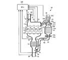
- 1 is a schematic configuration diagram illustrating an exhaust gas circulation device for an internal combustion engine according to a first embodiment of the present invention.
- 1 is a schematic perspective view showing an EGR cooler and an EGR valve according to a first embodiment of the present invention.
- 1 is a schematic block diagram showing an exhaust circulation device according to a first embodiment of the present invention and a configuration around it. It is a schematic block diagram which shows the structure of the cooling water circuit which concerns on the 1st Embodiment of this invention. It is a flowchart for demonstrating EGR control which concerns on the 1st Embodiment of this invention. It is a schematic block diagram which shows the exhaust-gas-circulation apparatus of the internal combustion engine which concerns on the 2nd Embodiment of this invention.
- FIGS. 1 to 5 a first embodiment of the present invention will be described with reference to FIGS. 1 to 5.
- the exhaust gas circulation device according to the present invention is applied to a vehicle equipped with a 4-cylinder gasoline engine.
- the engine 1 includes a cylinder head 10 and a cylinder block (not shown), and the cylinder head 10 and the cylinder block form four cylinders 5.
- combustion chambers 7 are respectively defined by pistons.
- the cylinder head 10 is formed with an intake port for introducing outside air into the cylinder 5 and an exhaust port for discharging exhaust gas from the cylinder 5.
- each intake port an injector for injecting fuel is installed, and the injected fuel is mixed with air and introduced into the combustion chamber 7 as an air-fuel mixture.
- the cylinder head 10 is provided with an ignition plug 15 for igniting the air-fuel mixture introduced into each combustion chamber 7.
- the ignition plug 15 is controlled in ignition timing by an ECU (Electronic Control Unit) 100 described later. It is like that.
- the injector is configured by an electromagnetically driven on-off valve. When a predetermined voltage is applied by the ECU 100, the injector is opened and fuel is injected into the intake port of each cylinder 5.
- the engine 1 further has an intake manifold 11 a connected to the cylinder head 10, and the intake manifold 11 a constitutes a part of the intake passage 11.
- the intake passage 11 is formed inside the intake pipe 14, and is provided with an air cleaner and an air flow meter 22 (not shown) in order from the upstream side.
- the intake passage 11 is further provided with a throttle valve 18 for adjusting the intake air amount on the upstream side of the intake manifold 11a.
- the intake manifold 11a is provided with an intake air temperature sensor 23 and a pressure sensor 24.
- the throttle valve 18 is constituted by an electronically controlled on-off valve whose opening degree can be adjusted steplessly.
- the flow area of the intake air is reduced under a predetermined condition, and the supply amount of the intake air is reduced. To be adjusted.
- the ECU 100 controls the throttle motor installed in the throttle valve 18 to adjust the opening degree of the throttle valve 18.
- the engine 1 further has an exhaust manifold 12 a connected to the cylinder head 10, and the exhaust manifold 12 a constitutes a part of the exhaust passage 12.
- a catalyst device 13 made of, for example, a three-way catalyst is disposed.
- An A / F sensor 25 is disposed in the exhaust passage 12 upstream of the catalyst device 13.
- An exhaust temperature sensor 26 is disposed in the exhaust passage 12 on the downstream side of the catalyst device 13. Output signals of the A / F sensor 25 and the exhaust temperature sensor 26 are input to the ECU 100.
- the engine 1 further includes an EGR device 30.
- the EGR device 30 recirculates a part of the exhaust gas flowing through the exhaust passage 12 to the intake passage 11 and supplies it as EGR gas to the combustion chamber 7 of each cylinder 5, thereby reducing the combustion temperature, thereby generating the amount of NOx generated. Is to be reduced. In addition, the pumping loss is reduced and the fuel consumption is improved.
- the EGR device 30 includes an EGR pipe 33 that connects the intake manifold 11a and the exhaust pipe 16 and has an EGR passage 34 formed therein.
- the EGR pipe 33 is provided with an EGR cooler 31 and an EGR valve 32 for cooling the EGR gas flowing through the EGR passage 34 in order from the upstream side of the EGR gas flow.
- a delivery pipe (not shown) made of stainless steel is arranged on the intake manifold 11a.
- the delivery pipe is composed of a tubular member that allows the EGR passage 34 and the intake manifold 11a to communicate with each other.
- the EGR device 30 further includes a heating pipe 45 that heats an EGR pipe 33 between an EGR cutoff valve 35 and an EGR cooler 31 described later.
- the heating pipe 45 is made of a metal member such as stainless steel, and the heating pipe 45 is installed on the outer peripheral side of the EGR pipe 33 so that the heating pipe 45 and the EGR pipe 33 form a double pipe structure. .
- a cooling water channel 46 is formed by the outer peripheral surface of the EGR pipe 33 and the inner peripheral surface of the heating pipe 45.
- the cooling water passage 46 constitutes a part of a third path 49 of the cooling water circuit 40 described later, and the cooling water of the engine 1 is supplied through the inflow port 46a and discharged through the discharge port 46b. It is like that. That is, the piping 45 for heating which concerns on this Embodiment comprises the heating part which concerns on this invention.
- the heating pipe 45 is preferably installed at a position where the effect of heating by the cooling water is greater than the exhaust gas flowing through the exhaust passage 12. For this reason, in the present embodiment, as shown in FIG. 1, the upstream end of the heating pipe 45 is located at a predetermined distance from the branch part of the exhaust pipe 16 and the EGR pipe 33.
- the EGR cooler 31 is mainly formed of stainless steel, and has a configuration in which a cooling water pipe is stretched around the outer periphery of the EGR gas passage in the housing 31a, as shown in FIGS. Yes.
- the EGR gas supplied from the EGR passage 34 is cooled by heat exchange with the cooling water flowing through the cooling water pipe when passing through the EGR gas passage, and is guided downstream.
- the EGR cooler 31 is connected to an inlet pipe 31d for introducing the cooling water that has passed through the engine 1 and an outlet pipe 31e that is connected to an unillustrated inlet pipe of the EGR valve 32. It flows into the cooling water pipe from 31d and is discharged from the outlet pipe 31e.
- the EGR valve 32 is provided with an EGR valve driving means 32a provided therein, and a valve body 32b that opens and closes the EGR passage 34 at the distal end thereof, with the base end portion being inserted into the EGR valve driving means 32a. Is provided with a shaft 32c.
- the EGR valve driving means 32a is constituted by, for example, a step motor or a DC motor.
- the ECU 100 controls the energization of the EGR valve driving means 32a, whereby the shaft 32c is reciprocated in the axial direction by the electromagnetic force and the biasing force of a spring (not shown), and the EGR passage 34 is opened and closed by the valve body 32b.
- the EGR valve 32 according to the present embodiment constitutes a second valve according to the present invention.
- the EGR valve 32 is mainly composed of a metal such as aluminum or stainless steel.
- An EGR valve water channel is formed in the housing 32d of the EGR valve 32 so as to surround the shaft 32c.
- An inlet pipe is connected to the upstream end of the EGR valve water channel, and the cooling water discharged from the outlet pipe 31e of the EGR cooler 31 is introduced into the EGR valve water channel via the inlet pipe.
- An outlet pipe 32f is connected to the downstream end of the EGR valve water channel.
- the cooling water flowing through the EGR valve water passage cools the shaft 32c and the valve body 32b that are exposed to high-temperature exhaust gas, and also cools the EGR valve driving means 32a.
- the ECU 100 adjusts the opening degree of the EGR valve 32 so as to connect the exhaust passage 12 and the intake passage 11 to adjust the amount of EGR gas introduced into the intake manifold 11a from the exhaust manifold 12a, that is, the exhaust gas recirculation amount. It has become.
- the housing 31a of the EGR cooler 31 is formed of a metal having thermal conductivity, and has fastening portions 31b and 31c at the upstream end portion and the downstream end portion, respectively.
- the housing 32d of the EGR valve 32 is also made of a metal having thermal conductivity, and has a fastening portion 32e at the upstream end.
- the EGR cooler 31 and the EGR valve 32 according to the present embodiment are fastened to each other by the fastening portions 31c and 32e without passing through the EGR pipe.
- These fastening portions 31c and 32e are constituted by, for example, flanges for hermetic coupling, and are fastened to each other by fastening means such as bolts or are fixed by a known method such as welding. Heat conduction between the EGR cooler 31 and the EGR valve 32 is possible via the fastening portions 31c and 32e.
- fastening portion 31b of the EGR cooler 31 is fastened to the fastening portion 33a formed on the EGR pipe 33.
- These fastening portions 31b and 33a are also constituted by, for example, airtight coupling flanges, and are fastened and fixed to each other by fastening means such as bolts, or are fixed by a known method such as welding.
- the EGR device 30 further includes an EGR cutoff valve 35 on the upstream side of the EGR cooler 31.
- the EGR shut-off valve 35 is made of a metal such as aluminum or stainless steel, and is configured by a valve that can take a fully open state and a fully closed state, such as a diaphragm valve or an electromagnetically driven valve. Yes.
- the EGR shut-off valve 35 shuts off the EGR passage 34 under predetermined operating conditions and prevents the exhaust gas discharged to the exhaust manifold 12a from flowing into the EGR device 30.
- the EGR cutoff valve 35 may be configured by a valve that can take an arbitrary state between an open state and a closed state.
- the EGR cutoff valve 35 according to the present embodiment constitutes a first valve according to the present invention.
- each part of the engine 1 outputs a detection signal corresponding to the depression amount of the cooling water temperature sensor 21, the exhaust temperature sensor 26, and the accelerator pedal.
- a degree sensor 29, a throttle opening sensor 27 that outputs a detection signal corresponding to the opening of the throttle valve 18, a valve opening sensor 36, and a shut-off valve opening sensor 39 are provided.
- a vehicle on which the engine 1 is loaded is provided with an engine rotation speed sensor 37 and an outside air temperature sensor 38 that detect the rotation speed of the crankshaft of the engine 1 and output it as the engine rotation speed.
- the cooling water temperature sensor 21 is disposed in a water jacket formed in the cylinder block of the engine 1 and outputs a detection signal corresponding to the cooling water temperature THW of the engine 1 to the ECU 100.
- the air flow meter 22 is disposed on the upstream side of the throttle valve 18 in the intake passage 11 and outputs a detection signal corresponding to the intake air amount to the ECU 100.
- the intake air temperature sensor 23 is disposed in the intake manifold 11a, and outputs a detection signal corresponding to the intake air temperature to the ECU 100.
- the pressure sensor 24 is disposed in the intake manifold 11a and outputs a detection signal corresponding to the intake pressure to the ECU 100.
- the A / F sensor 25 is disposed in the exhaust passage 12 upstream of the catalyst device 13 and outputs a detection signal corresponding to the oxygen concentration (exhaust A / F) in the exhaust gas to the ECU 100.
- the exhaust temperature sensor 26 is disposed in the exhaust passage 12 on the downstream side of the catalyst device 13 and outputs a detection signal corresponding to the temperature of the exhaust gas to the ECU 100.
- the valve opening sensor 36 outputs a signal corresponding to the opening of the EGR valve 32 to the ECU 100.
- the outside air temperature sensor 38 outputs a signal representing the outside air temperature to the ECU 100.
- the shutoff valve opening sensor 39 outputs a signal corresponding to the opening of the EGR shutoff valve 35 to the ECU 100.
- the ECU 100 is mounted on a vehicle on which the engine 1 is mounted. As shown in FIG. 3, the ECU 100 includes a CPU (Central Processing Unit) 101, a ROM (Read Only Memory) 102, a RAM (Random Access Memory) 103, a backup RAM 104, and the like. I have. Note that the ECU 100 according to the present embodiment constitutes a part of the exhaust gas circulation device according to the present invention.
- a CPU Central Processing Unit
- ROM Read Only Memory
- RAM Random Access Memory
- the ROM 102 is referred to when executing various control programs including a program for performing EGR control for adjusting the exhaust gas recirculation amount and a control program for controlling the fuel injection amount for the cylinder 5 and these various control programs. Maps are stored.
- the CPU 101 executes various arithmetic processes based on various control programs and maps stored in the ROM 102.
- the RAM 103 temporarily stores calculation results by the CPU 101, data input from the above-described sensors, and the like.
- the backup RAM 104 is configured by a nonvolatile memory, and stores data to be saved when the engine 1 is stopped, for example.
- the CPU 101, the ROM 102, the RAM 103, and the backup RAM 104 are connected to each other via the bus 107, and are also connected to the input interface 105 and the output interface 106.
- the input interface 105 outputs a cooling water temperature sensor 21, an air flow meter 22, an intake air temperature sensor 23, a pressure sensor 24, an A / F sensor 25, an exhaust gas temperature sensor 26, and an accelerator opening that outputs a detection signal corresponding to the depression amount of the accelerator pedal.
- a number sensor 37, an outside air temperature sensor 38, a shut-off valve opening sensor 39, and the like are connected.
- the output interface 106 is connected to the spark plug 15, the throttle valve 18, the EGR valve 32, the EGR cutoff valve 35, an injector (not shown), and the like.
- the ECU 100 executes various controls of the engine 1 including EGR control and fuel injection amount control based on the outputs of the various sensors described above.
- FIG. 4 is a schematic diagram showing a cooling water circuit 40 that supplies cooling water to the EGR device 30 according to the present embodiment.
- the cooling water circuit 40 supplies the cooling water discharged from the water pump 44 in the order of the engine 1, the heater core 41, the EGR cooler 31, the EGR valve 32, and the throttle valve 18, and returns to the water pump 44.
- a part of the cooling water branched from the first path 47 by a three-way valve (not shown) installed downstream of the cylinder head 10 constituting the engine 1 and supplied from the engine 1 to the radiator 42 and returned to the water pump 44 And two paths 48.
- the cooling water circuit 40 further includes a third path 49 branched from the first path 47 on the downstream side of the heater core 41 and joined to the first path 47 on the upstream side of the throttle valve 18 via the heating pipe 45. ing.
- the cooling water returning through the first path 47 is heated by heat exchange with the cylinder block and the cylinder head 10 constituting the engine 1. A part of the cooling water is cooled by heat exchange with the heater core 41 and then supplied to the EGR cooler 31. In addition, after the heat exchange with the heater core 41 is performed, the remaining cooling water flows into the third path 49 and is cooled by heat exchange with the EGR pipe 33 in the heating pipe 45. Then, on the upstream side of the throttle valve 18, it merges with the cooling water that circulates through the first path 47.
- the cooling water that circulates in the second path 48 is branched from the first path 47 by a thermostat (not shown) installed downstream of the cylinder head 10, it is supplied to the radiator 42 and cooled by heat exchange with the outside air.
- the thermostat has a radiator 42 and a water pump 44. The path between is supposed to be blocked.
- the thermostat gradually opens the path between the radiator 42 and the water pump 44 as the cooling water temperature THW increases, and the amount of cooling water returning to the second path 48 relative to the amount of cooling water returning to the first path 47. The ratio of is going to increase.
- EGR cutoff valve 35 When ECU 100 constituting the control device according to the embodiment of the present invention further determines that cooling water temperature THW is lower than predetermined value THWth based on a signal input from cooling water temperature sensor 21, EGR cutoff valve 35 is set. It shifts to the closed state.
- the predetermined value THWth is set to a temperature at which the warm-up of the engine 1 is completed and EGR control is started, for example, 70 ° C.
- the dew point temperature of the exhaust gas is 60 ° C. or less. Therefore, when the cooling water temperature THW is 70 ° C. or higher, the generation of condensed water in the EGR cooler 31 can be suppressed even if the exhaust gas is supplied to the EGR device 30. Further, since the cooling water is also supplied to the EGR valve 32, the generation of condensed water in the EGR valve 32 can be suppressed.
- the EGR device 30 according to the present embodiment is not provided with an EGR pipe that is not heated by the cooling water between the EGR cooler 31 and the EGR valve 32. Therefore, in the conventional EGR device, when the cooling water temperature THW reaches the predetermined value THWth and the EGR shut-off valve 35 shifts from the fully closed state to the fully opened state, the EGR pipe is not yet sufficiently warmed up, In some cases, condensed water was generated. In contrast, the EGR device 30 according to the present embodiment cools the EGR gas between the EGR cooler 31 and the EGR valve 32 when the warm-up is completed and the EGR shut-off valve shifts to the open state, and the condensed water is discharged. It has a configuration that does not occur.
- the ECU 100 when the EGR control is not executed and the EGR valve 32 is shifted to the fully closed state, the ECU 100 also shifts the EGR cutoff valve 35 to the fully closed state, so that the EGR valve 32 is fully closed. In some cases, the exhaust pulsation prevents the exhaust from flowing into the EGR device 30. Thus, when the EGR valve 32 is in the fully closed state, the EGR cutoff valve 35 is also in the fully closed state. When the EGR valve 32 is in the open state, that is, in a state other than the fully closed state, the EGR cutoff valve 35 is Is supposed to be fully open.
- ECU 100 determines that coolant temperature THW has exceeded 70 ° C. based on a signal input from coolant temperature sensor 21, ECU 100 shifts EGR shut-off valve 35 to a fully open state and starts EGR control. It has become.
- the ECU 100 determines that the warm-up has been completed and shifts the EGR shut-off valve 35 to the open state, the ECU 100 controls the EGR valve 32 to execute EGR control for adjusting the flow rate of EGR gas. .
- the ECU 100 stores an opening degree map in which the engine speed and engine load are associated with the opening degree of the EGR valve 32 in the ROM 102, and is detected by the engine speed and the air flow meter 22 detected by the engine speed sensor 37.
- the opening degree of the EGR valve 32 is set with reference to the opening degree map stored in the ROM 102.
- the ECU 100 stores an engine load map in which the intake air amount is associated with the engine load in the ROM 102 in advance.
- the correspondence between the intake air amount and the engine load is obtained in advance by experimental measurement.
- the engine load may be calculated by a known method such as a method of calculating from the fuel injection amount in the engine 1 instead of the intake air amount.
- FIG. 5 is a flowchart for explaining the EGR control according to the embodiment of the present invention. Note that the following processing is executed at predetermined time intervals by the CPU 101 constituting the ECU 100 and realizes a program that can be processed by the CPU 101.
- ECU 100 first determines whether or not cooling water temperature THW is equal to or higher than a predetermined value THWth based on a signal acquired from cooling water temperature sensor 21 (step S1).
- ECU 100 determines that coolant temperature THW is equal to or higher than predetermined value THWth (YES in step S1), ECU 100 condenses in EGR cooler 31 and EGR valve 32 even if the exhaust gas flows into EGR passage 34 as EGR gas. Since no water is generated, the EGR shut-off valve 35 is shifted from the closed state to the open state (step S2). At this time, since the EGR pipe 33 is also heated by the cooling water supplied to the cooling water passage 46, no condensed water is generated in the EGR pipe 33.
- step S1 when it is determined that the cooling water temperature THW has not reached the predetermined value THWth (NO in step S1), the exhaust gas flows into the EGR passage 34 and becomes equal to or lower than the dew point temperature in the EGR cooler 31 or the EGR valve 32.
- the EGR shut-off valve 35 is shifted to a closed state (step S3), and the flow shifts to RETURN.
- the cooling water heated by the engine 1 is supplied to the cooling water passage 46, the EGR pipe 33 is heated even if hot exhaust gas does not flow in.
- step S3 if the EGR cutoff valve 35 is already closed, the ECU 100 continues the closed state of the EGR cutoff valve 35.
- the ECU 100 executes the control of the EGR valve 32 according to the combustion state of the engine 1. Specifically, the ECU 100 acquires a signal representing the engine speed from the engine speed sensor 37 and calculates the engine load based on the signal input from the air flow meter 22 and the engine load map stored in the ROM 102. Then, the ECU 100 sets the opening degree of the EGR valve 32 based on the opening degree map stored in the ROM 102.
- the exhaust gas circulation device for an internal combustion engine can heat the EGR pipe 33 between the EGR shut-off valve 35 and the EGR cooler 31, It is possible to suppress the temperature of the EGR pipe 33 from decreasing to near the dew point temperature during operation. Therefore, the generation of condensed water in the EGR pipe 33 upstream of the EGR cooler 31 can be suppressed, and corrosion of the EGR pipe 33 can be suppressed.
- the EGR device 30 heats the EGR pipe 33 by exchanging heat with the cooling water of the engine 1, it can be realized without providing a separate heat source, and the cost can be reduced as compared with the case where a separate heat source is provided. it can.
- the EGR gas can be cooled by the cooling water supplied to the heating pipe 45 after the warm-up of the engine 1 is completed, the cooling of the EGR gas by the EGR cooler 31 can be shared by the heating pipe 45 as well. Become. Therefore, the EGR cooler 31 can have a simple configuration and the cost can be reduced.
- the heating pipe 45 and the EGR pipe 33 form a double pipe structure, the heating pipe 45 can be realized with a simple structure, the cost can be reduced, and the EGR device 30 can be easily installed in the vehicle. become.
- the ECU 100 controls the EGR shut-off valve 35 to shift from the closed state to the open state when the cooling water temperature becomes equal to or higher than the threshold value, the ECU 100 controls the opening degree of the EGR valve 32.
- the exhaust gas recirculation amount can be controlled in accordance with the above. Further, since the EGR gas can be flowed into the EGR passage 34 after the warm-up is completed, the EGR gas temperature does not decrease below the dew point temperature, and condensed water is generated in the EGR pipe 33 and the EGR cooler 31. This can be suppressed.
- the ECU 100 has described the case where the EGR control is executed when the coolant temperature THW becomes equal to or higher than the predetermined value THWth.
- the temperature of the portion upstream of the heating pipe 45 varies depending on the outside air temperature. Therefore, ECU 100 may correct predetermined value THWth according to the outside air temperature.
- the temperature on the upstream side of the heating pipe 45 in the EGR pipe 33 is also high. Therefore, even when the cooling water temperature is lower than the predetermined value THWth, the temperature of the EGR pipe 33 is higher than the dew point temperature of the EGR gas.
- the cooling water temperature needs to be higher than the predetermined value THWth.
- the ECU 100 corrects the predetermined value THWth higher as the outside air temperature is higher, and corrects the predetermined value THWth lower as the outside air temperature is lower, based on the signal input from the outside air temperature sensor 38.
- the ECU 100 corrects the predetermined value THWth in a range where the corrected predetermined value THWth is higher than the dew point temperature of the EGR gas. That is, ECU 100 according to the present embodiment constitutes a control unit according to the present invention.
- the ECU 100 can set the conditions for shifting the EGR valve 32 and the EGR shut-off valve 35 from the closed state to the open state according to the outside air temperature, and therefore the EGR valve 32 and the EGR shut-off valve 35 according to the outside air temperature. Can be controlled. Therefore, the ECU 100 can control the EGR valve 32 according to the temperature environment of the EGR pipe 33, and can suitably suppress the generation of condensed water.
- the present invention is not limited to this, and the cooling water is heated from the engine 1 without passing through the heater core 41. You may make it supply to the piping 45 for work. In this case, since the cooling water is supplied to the heating pipe 45 without lowering the temperature due to heat exchange in the heater core 41, the heating pipe 45 can be heated in a shorter time.
- the EGR pipe 33 is heated by the heating pipe 45.
- the present invention is not limited to this, and the EGR pipe is heated by heat transfer or radiant heat from the exhaust manifold 12a. May be.
- an EGR pipe 61 on the upstream side of the EGR cooler 31 is installed in the vicinity of the exhaust manifold 12a.
- the distance between the EGR pipe 61 and the exhaust manifold 12a is set such that the radiant heat of the exhaust manifold 12a reaches the EGR pipe 61 and can heat the EGR pipe 61 when the engine 1 is warmed up. That is, in the present embodiment, the exhaust manifold 12a constitutes the heating unit according to the present invention.
- the EGR pipe 61 is heated by the radiant heat of the exhaust manifold 12a even when the EGR shut-off valve 35 is fully closed and high-temperature exhaust gas does not flow into the EGR passage 62 formed in the EGR pipe 61. Therefore, when the warm-up of the engine 1 is finished and the EGR shut-off valve 35 shifts to the fully open state, the exhaust gas does not fall below the dew point temperature even if it flows into the EGR passage 62, and the generation of condensed water is suppressed. it can.
- the vicinity of the upstream end of the EGR pipe 61 is heated by the high-temperature exhaust gas flowing through the exhaust passage 12 in the same manner as the EGR device 30 according to the first embodiment. Therefore, the EGR pipe 61 only needs to be located near the exhaust manifold 12a at a position where the effect of heating by the exhaust gas is low.
- the EGR pipe 61 may be heated by heat transfer from the exhaust manifold 12a instead of radiant heat by the exhaust manifold 12a.
- the entire EGR pipe 61 positioned on the upstream side of the EGR cooler 31 can be heated by heat transfer.
- the EGR pipe 61 may be heated by radiant heat and heat transfer by the exhaust manifold 12a.
- the EGR pipe 33 is heated by the radiant heat of the exhaust manifold 12a. .
- the EGR devices 30 and 50 are applied to the engine 1 that does not include the turbo unit.
- the present invention is not limited to this, and the EGR devices 30 and 50 include the turbo unit that includes the turbo unit. May be applied.
- the EGR devices 30 and 50 may constitute a so-called HPL (High-Pressure Loop) that acquires exhaust gas from the upstream side of the turbine wheel and recirculates it as EGR gas to the downstream side of the compressor wheel. Further, the EGR devices 30 and 50 may constitute an LPL (Low-Pressure Loop) that acquires exhaust gas from the downstream side of the turbine wheel and recirculates it as EGR gas to the upstream side of the compressor wheel.
- HPL High-Pressure Loop
- LPL Low-Pressure Loop
- the EGR pipes 33 and 61 are branched from the exhaust pipe 16 on the downstream side of the catalyst device 13 .
- the present invention is not limited to this, and the EGR pipes 33 and 61 are connected to the catalyst device 13. It may be branched from the upstream exhaust pipe 16 or the exhaust manifold 12a.
- the EGR pipes 33 and 61 may be formed integrally with the exhaust manifold 12a, or the EGR pipes 33 and 61 and the exhaust manifold 12a are airtight. They may be connected to each other by a coupling flange or the like.
- the EGR cooler 31 and the EGR valve 32 are formed as separate parts.
- the EGR cooler 31 and the EGR valve 32 may be formed so as to be accommodated in one housing.
- the EGR apparatuses 30 and 50 demonstrated the case where it applied to the vehicle carrying the engine 1 comprised by the gasoline engine, it is not limited to this,
- the EGR apparatuses 30 and 50 are well-known internal combustion engines, such as a diesel engine. It may be applied to a vehicle equipped with an engine.
- the EGR devices 30 and 50 are applied to the port injection type engine in which the fuel is injected into the intake port.
- the present invention is not limited to this, and the fuel is directly supplied to each combustion chamber 7.
- the EGR devices 30 and 50 may be applied to an in-cylinder injection engine that is injected. Further, the EGR devices 30 and 50 may be applied to an engine in which both in-cylinder injection and port injection are performed.
- the EGR devices 30 and 50 may be applied not only to a vehicle that uses only the engine 1 as a power source, but also to a hybrid vehicle that uses an engine and a rotating electrical machine as a power source.
- the exhaust gas circulation device according to the present invention has the effect of suppressing the generation of condensed water in the EGR pipe upstream from the EGR cooler and suppressing the corrosion of the EGR pipe. It is useful for an exhaust gas circulation device of an internal combustion engine.
Landscapes
- Engineering & Computer Science (AREA)
- Chemical & Material Sciences (AREA)
- Combustion & Propulsion (AREA)
- Mechanical Engineering (AREA)
- General Engineering & Computer Science (AREA)
- Chemical Kinetics & Catalysis (AREA)
- Exhaust-Gas Circulating Devices (AREA)
- Output Control And Ontrol Of Special Type Engine (AREA)
- Combined Controls Of Internal Combustion Engines (AREA)
Abstract
Description
5 気筒
7 燃焼室
11 吸気通路
11a 吸気マニホールド
12 排気通路
12a 排気マニホールド
13 触媒装置
16 排気管
18 スロットルバルブ
21 冷却水温センサ
22 エアフロメータ
23 吸気温センサ
24 圧力センサ
26 排気温センサ
30 EGR装置
31 EGRクーラ
32 EGRバルブ
32a リニアソレノイド
33 EGR管
34 EGR通路
35 EGR遮断弁
36 バルブ開度センサ
37 エンジン回転数センサ
38 外気温センサ
39 遮断弁開度センサ
40 冷却水回路
45 加熱用配管
46 冷却水路
50 EGR装置
61 EGR管
100 ECU
Claims (6)
- 内燃機関から排気通路に排出された排気の一部をEGRガスとして吸気通路に循環させる内燃機関の排気循環装置であって、
前記排気通路と前記吸気通路とを連通するEGR通路が形成されたEGR管と、
前記排気通路側に設けられ、開状態と閉状態との間で駆動されるとともに、前記閉状態の場合に前記EGRガスが前記EGR通路に流入するのを遮断する第1の弁と、
前記第1の弁よりも前記吸気通路側に設けられ、開状態と閉状態との間で駆動されるとともに、前記EGRガスが前記吸気通路に流入する量を調整する第2の弁と、
前記第1の弁と前記第2の弁の間の前記EGR管に設けられ、前記EGR通路に流入するEGRガスを冷却するEGRクーラと、
前記第1の弁から前記EGRクーラまでの間の前記EGR管を加熱する加熱部と、を備えたことを特徴とする内燃機関の排気循環装置。 - 前記加熱部は、前記内燃機関の冷却水との熱交換により前記EGR管を加熱することを特徴とする請求項1に記載の内燃機関の排気循環装置。
- 前記加熱部および前記EGR管が2重管構造を形成するよう前記加熱部が前記EGR管の外周側に設置されることを特徴とする請求項1または請求項2に記載の内燃機関の排気循環装置。
- 前記内燃機関の冷却水の温度を検出する水温センサと、
前記水温センサによって検出された前記冷却水の温度が閾値以上となった場合に、前記第1の弁が閉状態から開状態に移行するよう制御するとともに前記第2の弁の開度を制御する制御部と、を備えたことを特徴とする請求項1ないし請求項3のいずれか1の請求項に記載の内燃機関の排気循環装置。 - 外気温を検出する外気温センサをさらに備え、
前記制御部は、前記外気温センサにより検出された外気温に応じて前記閾値を設定することを特徴とする請求項4に記載の内燃機関の排気循環装置。 - 前記加熱部は、前記内燃機関から前記排気通路に排気ガスを導入する排気マニホールドにより構成され、
前記EGR管は、前記加熱部からの輻射熱で加熱されることを特徴とする請求項1に記載の内燃機関の排気循環装置。
Priority Applications (5)
| Application Number | Priority Date | Filing Date | Title |
|---|---|---|---|
| CN201180030558.9A CN102959225B (zh) | 2011-03-24 | 2011-03-24 | 内燃机的排气循环装置 |
| DE112011105087.9T DE112011105087T5 (de) | 2011-03-24 | 2011-03-24 | Abgasrückführungsvorrichtung einer Brennkraftmaschine |
| US13/639,705 US20130019848A1 (en) | 2011-03-24 | 2011-03-24 | Exhaust gas recirculation apparatus of internal combustion engine |
| JP2012531169A JP5304952B2 (ja) | 2011-03-24 | 2011-03-24 | 内燃機関の排気循環装置 |
| PCT/JP2011/001732 WO2012127535A1 (ja) | 2011-03-24 | 2011-03-24 | 内燃機関の排気循環装置 |
Applications Claiming Priority (1)
| Application Number | Priority Date | Filing Date | Title |
|---|---|---|---|
| PCT/JP2011/001732 WO2012127535A1 (ja) | 2011-03-24 | 2011-03-24 | 内燃機関の排気循環装置 |
Publications (1)
| Publication Number | Publication Date |
|---|---|
| WO2012127535A1 true WO2012127535A1 (ja) | 2012-09-27 |
Family
ID=46878739
Family Applications (1)
| Application Number | Title | Priority Date | Filing Date |
|---|---|---|---|
| PCT/JP2011/001732 Ceased WO2012127535A1 (ja) | 2011-03-24 | 2011-03-24 | 内燃機関の排気循環装置 |
Country Status (5)
| Country | Link |
|---|---|
| US (1) | US20130019848A1 (ja) |
| JP (1) | JP5304952B2 (ja) |
| CN (1) | CN102959225B (ja) |
| DE (1) | DE112011105087T5 (ja) |
| WO (1) | WO2012127535A1 (ja) |
Cited By (5)
| Publication number | Priority date | Publication date | Assignee | Title |
|---|---|---|---|---|
| JP2014109207A (ja) * | 2012-11-30 | 2014-06-12 | Daihatsu Motor Co Ltd | 内燃機関 |
| JP2014196853A (ja) * | 2013-03-29 | 2014-10-16 | トヨタ自動車株式会社 | グロープラグの制御装置 |
| JP2016125404A (ja) * | 2014-12-26 | 2016-07-11 | マツダ株式会社 | エンジンの排気ガス還流装置 |
| WO2017034043A1 (ja) * | 2016-09-26 | 2017-03-02 | 株式会社小松製作所 | Egr装置、およびこれを備えたダンプトラック |
| CN111706448A (zh) * | 2019-03-18 | 2020-09-25 | 丰田自动车株式会社 | 排气再循环阀预热装置 |
Families Citing this family (14)
| Publication number | Priority date | Publication date | Assignee | Title |
|---|---|---|---|---|
| JP6213322B2 (ja) * | 2014-03-18 | 2017-10-18 | トヨタ自動車株式会社 | 内燃機関 |
| PL223578B1 (pl) * | 2014-04-03 | 2016-10-31 | Sindtech Spółka Z Ograniczoną Odpowiedzialnością | Sposób i instalacja do dostarczania wody lub innej pary do powietrza wlotowego silnika wewnętrznego spalania |
| KR101542990B1 (ko) * | 2014-06-05 | 2015-08-07 | 현대자동차 주식회사 | 이지알쿨러로 냉각수를 선택적으로 공급하는 냉각수 제어밸브 |
| JP6295996B2 (ja) * | 2014-06-19 | 2018-03-20 | トヨタ自動車株式会社 | 過給機付き内燃機関 |
| GB2535996B (en) * | 2015-02-27 | 2019-12-11 | Ford Global Tech Llc | A low condensation LP EGR System |
| JP6123841B2 (ja) | 2015-05-13 | 2017-05-10 | トヨタ自動車株式会社 | 内燃機関の制御装置 |
| DE102016113605B4 (de) * | 2015-07-24 | 2024-02-01 | MAGNETI MARELLI S.p.A. | Verfahren zum Bestimmen der angestrebten Temperatur eines Ansaugkollektors eines aufgeladenen Verbrennungsmotors, der mit einem EGR-Kreis zur Rückführung der Auslassgase mit niedrigem Druck versehen ist |
| EP3141734A1 (de) * | 2015-09-08 | 2017-03-15 | Winterthur Gas & Diesel Ltd. | Abgasrezirkulierungssystem für eine verbrennungsmaschine, verbrennungsmaschine, verfahren zum überwachen des abgasrezirkulierungsprozesses einer verbrennungsmaschine, verfahren zum nachrüsten eines abgasrezirkulierungssystems sowie kit zum nachrüsten eines verbrennungsmotors |
| CN105089864A (zh) * | 2015-09-18 | 2015-11-25 | 安徽江淮汽车股份有限公司 | 一种内置式油气分离装置 |
| CN105134421A (zh) * | 2015-10-15 | 2015-12-09 | 广西玉柴机器股份有限公司 | 发动机的egr系统 |
| DE102016200220B4 (de) * | 2016-01-12 | 2019-08-29 | Ford Global Technologies, Llc | Temperaturregulation in einem Abgasrückführungssystem |
| CN108252829B (zh) * | 2018-04-04 | 2023-10-24 | 吉林大学 | 一种双通道egr调节装置及其控制方法 |
| DE102018109688A1 (de) * | 2018-04-23 | 2019-10-24 | Volkswagen Aktiengesellschaft | Abgasrückführungsanordnung mit Wärmetauscher, Wärmetauscher und Brennkraftmaschine |
| EP3667054B1 (en) * | 2018-12-11 | 2024-09-04 | Marelli Europe S.p.A. | Fuel supply system for vehicles provided with pressure reducer with recovery of thermal energy, and method of adjustment of a fuel supply system for vehicles with thermal energy recovery |
Citations (6)
| Publication number | Priority date | Publication date | Assignee | Title |
|---|---|---|---|---|
| JP2005127137A (ja) * | 2003-10-21 | 2005-05-19 | Hino Motors Ltd | エンジンのegrシステム |
| JP2007262902A (ja) * | 2006-03-27 | 2007-10-11 | Isuzu Motors Ltd | エンジンの燃焼制御方法及び燃焼制御装置 |
| JP2007303381A (ja) * | 2006-05-11 | 2007-11-22 | Toyota Motor Corp | 内燃機関の排気還流装置 |
| JP2008232142A (ja) * | 2007-02-20 | 2008-10-02 | Usui Kokusai Sangyo Kaisha Ltd | クールドegrシステム及び該システム用熱交換器 |
| JP2010156242A (ja) * | 2008-12-26 | 2010-07-15 | Toyota Motor Corp | 異物捕集装置 |
| JP2010223179A (ja) * | 2009-03-25 | 2010-10-07 | Toyota Industries Corp | 低圧egr装置を備えた内燃機関 |
Family Cites Families (14)
| Publication number | Priority date | Publication date | Assignee | Title |
|---|---|---|---|---|
| JP3376136B2 (ja) * | 1994-12-20 | 2003-02-10 | マツダ株式会社 | 機械式過給機付エンジンの吸気装置 |
| JP3577961B2 (ja) * | 1998-02-27 | 2004-10-20 | トヨタ自動車株式会社 | 燃焼式ヒータを有する内燃機関 |
| JP4434401B2 (ja) * | 2000-01-19 | 2010-03-17 | 本田技研工業株式会社 | 内燃機関の排気浄化装置 |
| JP2003136155A (ja) * | 2001-10-30 | 2003-05-14 | Sanoh Industrial Co Ltd | 孔付き2重管の製造方法および該方法を実施するための成形型 |
| US6725848B2 (en) * | 2002-01-18 | 2004-04-27 | Detroit Diesel Corporation | Method of controlling exhaust gas recirculation system based upon humidity |
| JP2003336549A (ja) * | 2002-05-20 | 2003-11-28 | Denso Corp | 内燃機関のegr装置 |
| JP2005016390A (ja) * | 2003-06-25 | 2005-01-20 | Toyota Motor Corp | 内燃機関の排気還流装置 |
| WO2006058339A2 (en) * | 2004-11-29 | 2006-06-01 | Southwest Research Institute | Exhaust gas recirculation system with control of egr gas temperature |
| JP2008180180A (ja) * | 2007-01-25 | 2008-08-07 | Toyota Motor Corp | 内燃機関装置およびその制御方法並びに車両 |
| JP5112805B2 (ja) * | 2007-10-12 | 2013-01-09 | 日野自動車株式会社 | Egr装置 |
| JP4561817B2 (ja) * | 2007-12-04 | 2010-10-13 | トヨタ自動車株式会社 | 内燃機関 |
| US7971577B2 (en) * | 2008-09-05 | 2011-07-05 | Ford Global Technologies, Llc | EGR cooler defouling |
| DE102008043036B4 (de) * | 2008-10-22 | 2014-01-09 | Ford Global Technologies, Llc | Verbrennungsmotor mit Turboladung und Niederdruck-Abgasrückführung |
| US20110289914A1 (en) * | 2010-05-28 | 2011-12-01 | Caterpillar Inc. | Upstream egr restriction |
-
2011
- 2011-03-24 WO PCT/JP2011/001732 patent/WO2012127535A1/ja not_active Ceased
- 2011-03-24 US US13/639,705 patent/US20130019848A1/en not_active Abandoned
- 2011-03-24 CN CN201180030558.9A patent/CN102959225B/zh not_active Expired - Fee Related
- 2011-03-24 JP JP2012531169A patent/JP5304952B2/ja not_active Expired - Fee Related
- 2011-03-24 DE DE112011105087.9T patent/DE112011105087T5/de not_active Ceased
Patent Citations (6)
| Publication number | Priority date | Publication date | Assignee | Title |
|---|---|---|---|---|
| JP2005127137A (ja) * | 2003-10-21 | 2005-05-19 | Hino Motors Ltd | エンジンのegrシステム |
| JP2007262902A (ja) * | 2006-03-27 | 2007-10-11 | Isuzu Motors Ltd | エンジンの燃焼制御方法及び燃焼制御装置 |
| JP2007303381A (ja) * | 2006-05-11 | 2007-11-22 | Toyota Motor Corp | 内燃機関の排気還流装置 |
| JP2008232142A (ja) * | 2007-02-20 | 2008-10-02 | Usui Kokusai Sangyo Kaisha Ltd | クールドegrシステム及び該システム用熱交換器 |
| JP2010156242A (ja) * | 2008-12-26 | 2010-07-15 | Toyota Motor Corp | 異物捕集装置 |
| JP2010223179A (ja) * | 2009-03-25 | 2010-10-07 | Toyota Industries Corp | 低圧egr装置を備えた内燃機関 |
Cited By (8)
| Publication number | Priority date | Publication date | Assignee | Title |
|---|---|---|---|---|
| JP2014109207A (ja) * | 2012-11-30 | 2014-06-12 | Daihatsu Motor Co Ltd | 内燃機関 |
| JP2014196853A (ja) * | 2013-03-29 | 2014-10-16 | トヨタ自動車株式会社 | グロープラグの制御装置 |
| JP2016125404A (ja) * | 2014-12-26 | 2016-07-11 | マツダ株式会社 | エンジンの排気ガス還流装置 |
| WO2017034043A1 (ja) * | 2016-09-26 | 2017-03-02 | 株式会社小松製作所 | Egr装置、およびこれを備えたダンプトラック |
| JPWO2017034043A1 (ja) * | 2016-09-26 | 2017-08-31 | 株式会社小松製作所 | Egr装置、およびこれを備えたダンプトラック |
| US10808652B2 (en) | 2016-09-26 | 2020-10-20 | Komatsu Ltd. | EGR apparatus and dump truck including the same |
| CN111706448A (zh) * | 2019-03-18 | 2020-09-25 | 丰田自动车株式会社 | 排气再循环阀预热装置 |
| CN111706448B (zh) * | 2019-03-18 | 2022-05-10 | 丰田自动车株式会社 | 排气再循环阀预热装置 |
Also Published As
| Publication number | Publication date |
|---|---|
| US20130019848A1 (en) | 2013-01-24 |
| CN102959225B (zh) | 2015-11-25 |
| CN102959225A (zh) | 2013-03-06 |
| JPWO2012127535A1 (ja) | 2014-07-24 |
| DE112011105087T5 (de) | 2014-07-17 |
| JP5304952B2 (ja) | 2013-10-02 |
Similar Documents
| Publication | Publication Date | Title |
|---|---|---|
| JP5304952B2 (ja) | 内燃機関の排気循環装置 | |
| JP5799963B2 (ja) | 内燃機関の排気循環装置 | |
| US10473063B2 (en) | EGR system for internal-combustion engine | |
| CN101506502A (zh) | 内燃发动机的燃料喷射量控制装置 | |
| JP5577943B2 (ja) | 内燃機関 | |
| US20180298853A1 (en) | Egr cooling apparatus | |
| WO2012176286A1 (ja) | 内燃機関の制御装置 | |
| JP6536708B2 (ja) | 内燃機関のegrシステム | |
| JP5845619B2 (ja) | 内燃機関の排気還流装置 | |
| JP5830868B2 (ja) | 内燃機関の排気循環装置 | |
| JP6544376B2 (ja) | 内燃機関の冷却装置 | |
| JP5817202B2 (ja) | 内燃機関の排気循環装置 | |
| JP2012246805A (ja) | 内燃機関の排気循環装置 | |
| JP5672930B2 (ja) | 内燃機関の制御装置 | |
| US8434452B2 (en) | Control device for internal combustion engine | |
| US11047285B2 (en) | Control apparatus of internal combustion engine | |
| JP2018178853A (ja) | 内燃機関の冷却装置 | |
| JP6544375B2 (ja) | 内燃機関の冷却装置 | |
| JP2022021455A (ja) | Egrシステム | |
| JP2016145549A (ja) | エンジンの制御装置 |
Legal Events
| Date | Code | Title | Description |
|---|---|---|---|
| WWE | Wipo information: entry into national phase |
Ref document number: 201180030558.9 Country of ref document: CN |
|
| ENP | Entry into the national phase |
Ref document number: 2012531169 Country of ref document: JP Kind code of ref document: A |
|
| WWE | Wipo information: entry into national phase |
Ref document number: 13639705 Country of ref document: US |
|
| 121 | Ep: the epo has been informed by wipo that ep was designated in this application |
Ref document number: 11861860 Country of ref document: EP Kind code of ref document: A1 |
|
| WWE | Wipo information: entry into national phase |
Ref document number: 1120111050879 Country of ref document: DE Ref document number: 112011105087 Country of ref document: DE |
|
| 122 | Ep: pct application non-entry in european phase |
Ref document number: 11861860 Country of ref document: EP Kind code of ref document: A1 |