WO2012124594A1 - 航空機の制御システム、航空機、航空機の制御プログラム、及び航空機の制御方法 - Google Patents
航空機の制御システム、航空機、航空機の制御プログラム、及び航空機の制御方法 Download PDFInfo
- Publication number
- WO2012124594A1 WO2012124594A1 PCT/JP2012/055943 JP2012055943W WO2012124594A1 WO 2012124594 A1 WO2012124594 A1 WO 2012124594A1 JP 2012055943 W JP2012055943 W JP 2012055943W WO 2012124594 A1 WO2012124594 A1 WO 2012124594A1
- Authority
- WO
- WIPO (PCT)
- Prior art keywords
- control
- aircraft
- control surface
- rudder angle
- flight
- Prior art date
Links
- 238000000034 method Methods 0.000 title claims description 21
- 230000008859 change Effects 0.000 claims abstract description 65
- 238000001514 detection method Methods 0.000 claims abstract description 56
- 230000007257 malfunction Effects 0.000 claims abstract description 26
- 230000004044 response Effects 0.000 claims description 26
- 238000004364 calculation method Methods 0.000 claims description 25
- 230000001133 acceleration Effects 0.000 claims description 13
- 230000000694 effects Effects 0.000 claims description 11
- RZVHIXYEVGDQDX-UHFFFAOYSA-N 9,10-anthraquinone Chemical compound C1=CC=C2C(=O)C3=CC=CC=C3C(=O)C2=C1 RZVHIXYEVGDQDX-UHFFFAOYSA-N 0.000 abstract description 63
- 230000008569 process Effects 0.000 description 8
- 238000013016 damping Methods 0.000 description 4
- 230000014509 gene expression Effects 0.000 description 4
- 230000004048 modification Effects 0.000 description 4
- 238000012986 modification Methods 0.000 description 4
- 239000011159 matrix material Substances 0.000 description 3
- 238000010586 diagram Methods 0.000 description 2
- 230000005856 abnormality Effects 0.000 description 1
- 238000013528 artificial neural network Methods 0.000 description 1
- 230000002950 deficient Effects 0.000 description 1
- 238000001914 filtration Methods 0.000 description 1
- 239000000446 fuel Substances 0.000 description 1
- 239000002245 particle Substances 0.000 description 1
- 239000004065 semiconductor Substances 0.000 description 1
Images


Classifications
-
- B—PERFORMING OPERATIONS; TRANSPORTING
- B64—AIRCRAFT; AVIATION; COSMONAUTICS
- B64C—AEROPLANES; HELICOPTERS
- B64C13/00—Control systems or transmitting systems for actuating flying-control surfaces, lift-increasing flaps, air brakes, or spoilers
- B64C13/02—Initiating means
- B64C13/16—Initiating means actuated automatically, e.g. responsive to gust detectors
-
- G—PHYSICS
- G05—CONTROLLING; REGULATING
- G05D—SYSTEMS FOR CONTROLLING OR REGULATING NON-ELECTRIC VARIABLES
- G05D1/00—Control of position, course, altitude or attitude of land, water, air or space vehicles, e.g. using automatic pilots
- G05D1/0055—Control of position, course, altitude or attitude of land, water, air or space vehicles, e.g. using automatic pilots with safety arrangements
Definitions
- the present invention relates to an aircraft control system, an aircraft, an aircraft control program, and an aircraft control method.
- attitude control of an aircraft is performed by appropriately driving each control surface such as an elevator (elevator), an auxiliary wing (aileron), and a rudder (ladder) by an actuator according to a predetermined control signal.
- a control computer mounted on an aircraft detects information detected from various sensors such as an inertial sensor and an air data sensor provided on the aircraft, and a control end such as a control wheel.
- the steering angle command control signal for controlling the control surface is calculated based on the operation command signal, and the actuator drives each control surface according to the control angle command control signal, thereby maintaining the aircraft in a desired posture. Realizes stable flight.
- Patent Document 1 a control unit that controls the rotational motion of the airframe, and a distribution unit that calculates a control drive signal from an angular acceleration signal output from the control unit and distributes the control drive signal to a control control surface signal to be controlled.
- a non-linear compensator that corrects the input / output values of the control unit according to the aircraft's movement status is provided, so that if the control surface etc. fails or is damaged, the control control surface should not be used, Alternatively, a reconfiguration flight control system that can be reconfigured at a low degree of use is described.
- a reconfigurable flight control system is a reconfiguration of a flight control law that controls flight by controlling the rudder angle of a control surface in response to a failure or damage of the control surface. By performing the configuration, it will be possible to continue continuation and make safe landings.
- control plane / thrust integrated flight control that controls flight by controlling the rudder angle and engine thrust of the control surface when continuation of flight, safe landing, etc. are impossible only by reconfiguration of the flight control law By switching to the law, continuation of flight and safe landing are realized.
- the control surface / thrust integrated flight control law slows down the aircraft's motion response because the engine thrust is also used for flight control, so continue to control the aircraft using a reconfigurable flight control law as much as possible. It is preferable to switch from a reconfigurable flight control law to a control surface / thrust integrated flight control law.
- the present invention has been made in view of such circumstances, and the flight is performed by controlling the rudder angle of the control surface and the engine thrust from the control law for controlling the flight by controlling the rudder angle of the control surface. It is an object to provide an aircraft control system, an aircraft, an aircraft control program, and an aircraft control method capable of appropriately switching to a control law for controlling the aircraft.
- the aircraft control system, the aircraft, the aircraft control program, and the aircraft control method of the present invention employ the following means.
- the aircraft control system controls the flight by controlling the first control law for controlling the flight by controlling the steering angle of the control surface, the control angle of the control surface and the engine thrust.
- Control means for controlling flight by one of two control laws, control surface failure damage detection means for detecting that at least one of the control surfaces is malfunctioning, and control surface failure damage detection means by means of the control surface failure damage detection means
- a calculation means for calculating the rudder angle and the rate of change of the rudder angle required to realize desired flight characteristics based on the detection result by the control surface failure damage detection means when a malfunction is detected; It is necessary to switch from the first control law to the second control law by determining whether or not the rudder angle or the rate of change of the rudder angle calculated by the calculation means exceeds a changeable range. And a determination means for determining.
- the aircraft has a first control law for controlling flight by controlling the steering angle of the control surface, and a second control law for controlling flight by controlling the steering angle and engine thrust of the control surface. Flight is controlled by either.
- the aircraft is controlled by the first control law.
- the second control law also uses engine thrust for flight control, the response of the aircraft motion is slower than the first control law.
- the calculation means calculates the rudder angle and the rudder angle required to realize the desired flight characteristics based on the detection result of the control surface failure / damage detection means. The rate of change is calculated. Then, by determining whether the rudder angle calculated by the calculating unit or the change rate of the rudder angle exceeds a changeable range by the determining unit, switching from the first control law to the second control law is performed. Whether or not is necessary is determined.
- the present invention determines whether or not it is necessary to switch from the first control law to the second control law from the rudder angle of the control surface and the rate of change of the rudder angle, so that the control law is appropriately switched. Can do.
- the control means is a case where a malfunction of the control surface is detected by the control surface failure damage detection means, and is calculated by the calculation means.
- the rudder angle or the rate of change of the rudder angle does not exceed a changeable range
- the rudder surface in which a malfunction is detected by the rudder surface failure damage detection means is not used or the degree of use is reduced.
- the second control law is changed from the first control law to the second. Switch to control law.
- the control surface in which the malfunction is detected is not used or used. Since the first control law is reconfigured so as to reduce the degree of the above, switching from the first control law to the second control law can be suppressed.
- the control law of the aircraft is switched from the first control law to the second control law. The control law is switched only at.
- the required moment of the aircraft is calculated from the angular velocity and angular acceleration around the aircraft body axis calculated by the calculation means based on a response model indicating the motion characteristics of the aircraft.
- the amount of change is calculated, and the rudder angle and the rate of change of the rudder angle that satisfy the calculated required moment change amount are calculated.
- the required moment change amount of the aircraft is calculated from the angular velocity and angular acceleration around the aircraft body axis calculated based on the response model indicating the motion characteristics of the aircraft, and the calculated required moment is calculated. Since the rudder angle and the rudder angle change rate satisfying the amount of change are calculated, the rudder angle and rudder angle change rate necessary for realizing various aircraft modes such as roll mode, Dutch roll mode, and vertical short cycle mode are calculated. It can be easily calculated.
- the aircraft control system may be configured such that the calculation means calculates the required moment change amount of the aircraft in consideration of the effect of the engine gyro moment.
- the required moment change amount of the aircraft is calculated in consideration of the effect of the engine gyro moment, so the rudder angle and the rudder angle change rate necessary for realizing the aircraft mode can be calculated with higher accuracy. Can be calculated.
- an aircraft according to the present invention includes the aircraft control system described above.
- the aircraft is provided with the control system described above, so that the flight is performed by controlling the rudder angle of the control surface and the engine thrust from the control law for controlling the flight by controlling the rudder angle of the control surface. It is possible to appropriately switch to a control law that controls
- the aircraft control program according to the present invention further includes a first control law for controlling the flight by controlling the rudder angle of the control surface, a first control law for controlling the flight by controlling the rudder angle of the control surface and the engine thrust.
- An aircraft control program comprising: control means for controlling flight according to one of two control laws; and control surface failure damage detection means for detecting that at least one of the control surfaces is defective. The steering angle required to realize desired flight characteristics based on the detection result by the control surface failure damage detection means when the control surface malfunction detection means detects the control surface malfunction.
- calculating means for calculating the change rate of the rudder angle, and determining whether the rudder angle calculated by the calculation means or the change rate of the rudder angle exceeds a changeable range.
- determination means for determining necessity of switching to the second control law from the first control law, it is to function.
- the control law since the necessity of switching from the first control law to the second control law is determined from the rudder angle of the control surface and the rate of change of the rudder angle, the control law can be appropriately switched. .
- the aircraft control method includes a first control law for controlling flight by controlling a steering angle of a control surface, a first control law for controlling flight by controlling a steering angle and engine thrust of the control surface.
- a control method for an aircraft comprising: control means for controlling flight by one of two control laws; and control surface failure damage detection means for detecting that at least one of the control surfaces is malfunctioning, When a malfunction of the control surface is detected by the control surface failure damage detection means, the rudder angle and the rudder required to realize desired flight characteristics based on the detection result by the control surface failure damage detection means
- the control law since the necessity of switching from the first control law to the second control law is determined from the rudder angle of the control surface and the rate of change of the rudder angle, the control law can be appropriately switched. .
- the control law for controlling the flight by controlling the rudder angle of the control surface is appropriately switched from the control law for controlling the flight by controlling the rudder angle of the control surface and the engine thrust. It has an excellent effect of being able to.
- FIG. 1 is a block diagram showing a schematic configuration of an aircraft control system according to an embodiment of the present invention. It is a flowchart which shows the flow of a process of the switching necessity determination program which concerns on embodiment of this invention. It is a flowchart which shows the flow of a process of the switching necessity determination program which concerns on a modification.
- FIG. 1 is a block diagram showing a schematic configuration of an aircraft 1 to which an aircraft control system according to the present embodiment is applied.
- the aircraft 1 includes a sensor 2, a control surface 3, an engine 4, a cockpit 5, and a control system 6.
- the sensor 2 includes various sensors such as an inertial sensor and an air data sensor, and provides various state information regarding the state of the aircraft such as the angular velocity, attitude angle, acceleration, angle of attack, skid angle, pressure altitude, and airspeed of the aircraft.
- the acquired state information is output to the control system 6.
- the rudder surface 3 is an elevator that raises and lowers the nose, a rudder that changes the direction of the nose to the left and right, an auxiliary wing that tilts the fuselage to the left and right, and a wing shape of the main wing.
- a high lift device (flap) or the like that increases the lift is included, and the control surface 3 is driven by an actuator, which will be described later, so that the attitude of the airframe is controlled by an aerodynamic force.
- the engine 4 is, for example, a jet engine, and is driven by an engine control device, which will be described later.
- the fuel is mixed with the sucked air and burned, and thrust is obtained by reaction when the generated gas is ejected at high speed.
- instruments (not shown) indicating the flight state of the aircraft 1 are arranged, and as shown in FIG. 1, a control end 10, a throttle 11, a display warning unit 12, a switching unit 13, and the like.
- Various devices for realizing the operation of the aircraft 1 by the operator are arranged.
- the control end 10 is for controlling the control surface 3 by being operated by the operator, and an operation command signal for controlling the control surface when the operator operates the control end 10 is the control system 6. Is output. Note that, in the aircraft 1 according to the present embodiment, when control is performed according to the control surface / thrust integrated flight control law 22 described later, not only the control surface 3 but also the engine thrust is controlled by the control end 10.
- the throttle 11 is for controlling the engine thrust by being operated by the operator, and an operation command signal for controlling the engine thrust resulting from the operation of the throttle 11 by the operator is sent to the control system 6. Is output.
- the display warning unit 12 is controlled by turning on a predetermined warning light, or displaying a warning sound (sound, buzzer sound, etc.) or a display unit (not shown) provided in the cockpit 5. Based on the information from the system 6, a predetermined warning is notified to the pilot.
- the control surface 3 is damaged due to damage to the control surface, and the flight control law 20
- the necessity of switching the control surface / thrust integrated flight control law 22 occurs (details will be described later), the fact is notified to the pilot.
- the switching unit 13 outputs a switching command signal for switching between the flight control law 20 and the control surface / thrust integrated flight control law 22 of the control system 6, and the switching command signal is controlled based on an operation by the operator. 6 is output.
- the control system 6 includes a computer 15 for calculating a predetermined control signal, an actuator 16 for driving the control surface 3 based on the control signal output from the computer 15, and a control signal output from the computer 15.
- An engine control device 17 for driving the engine 4 and a control surface failure / damage detection device 18 for detecting the operation state of the control surface are provided.
- the computer 15 calculates a steering angle command control signal and a thrust command control signal, and includes a flight control law 20, a control surface / thrust integrated flight control law 22, a switching processor 19 for switching both control laws, and a switching.
- a switching necessity determining unit 24 for determining whether or not the switching is necessary.
- the flight control law 20 is a control law for controlling flight by controlling the rudder angle of the control surface 3, and in a state where each device such as the control surface 3 provided in the aircraft 1 is normal and is flying normally. It is a control law for realizing flight automatically or manually by a pilot.
- the computer 15 is based on the operation command signal from the control end 10 by the operator and the state information from the sensor 2. Generates a steering angle command control signal. All of the generated steering angle command control signals are output to the actuator 16, and the actuator 16 drives the control surface 3 according to the steering angle command control signal, and the attitude of the aircraft 1 is changed by controlling the steering angle or Maintained.
- the flight control law 20 is based on the detection result by the control surface failure damage detection device 18 so that the failed control surface 3 is not used or the degree of use is low so that the control surface is not in failure. It is possible to reconstruct a signal for distributing the control drive signal to the surface 3.
- the control surface / thrust integrated flight control law 22 is a control law for controlling flight by controlling the rudder angle of the control surface 3 and the engine thrust, and one of the control surfaces 3 of the aircraft 1 falls into a malfunctioning state. In this case, it is a control law for realizing flight automatically or manually by a pilot.
- the attitude is controlled based on the operation command signal from the control end 10 by the operator and the state information from the sensor 2.
- the computer 15 generates a steering angle command control signal and a thrust command control signal.
- the thrust command control signal is calculated based on the operation command signal and the state information. Therefore, even when the throttle 11 is operated, the computer 15 limits the effect of this operation.
- the calculation of the thrust command control signal based on the operation command signal and the state information is automatically prioritized.
- the generated rudder angle command control signal is output to the actuator 16, and the actuator 16 drives the rudder surface 3 according to the rudder angle command control signal.
- the generated thrust command control signal is output to the engine control device 17, and the engine control device 17 drives the engine 4 in accordance with the thrust command control signal. Then, the control surface 3 and the engine 4 are driven according to the steering angle command control signal and the thrust command control signal, whereby the steering angle and the engine thrust are controlled, and the attitude of the aircraft 1 is changed or maintained.
- a response adjustment for adjusting a difference in response speed between the engine 4 and the control surface 3 is provided in a path when the control angle command control signal is output from the control surface / thrust integrated flight control law 22 to the actuator 16.
- a filter 23 is provided. Adjustment of the response speed by the response adjustment filter 23 can be performed, for example, by filtering the steering angle command control signal.
- the response speed from the output of the thrust command control signal when the engine thrust is controlled until the engine 4 outputs the engine thrust based on the thrust command control signal is the steering angle command control when the steering angle is controlled. It takes more time than the response speed until the control surface 3 reaches the steering angle based on the steering angle command control signal after outputting the signal.
- a response adjustment filter 23 is provided to control the response speed to the same level as the response speed of the engine 4.
- the control surface failure / damage detection device 18 determines whether the control surface 3 is functioning normally based on the state information of the aircraft 1 output from the sensor 2, and any or all of the control surfaces 3 are inoperable or missing. If it is in a state, it is detected that there is a malfunction, and a malfunction signal and an aerodynamic coefficient indicating this are output to the switching necessity determination unit 24.
- the control surface failure damage detection apparatus 18 includes a candidate value calculation unit and an aerodynamic coefficient estimated value determination unit.
- the candidate value calculation unit included in the control surface failure damage detection apparatus 18 includes an arithmetic unit that stores an arithmetic rule based on an extended Kalman filter, an arithmetic unit that stores an arithmetic rule based on an unscented Kalman filter, and an arithmetic unit that stores an arithmetic rule based on a Fourier transform regression method. , And at least any two arithmetic units that store arithmetic rules based on the neural network method, and each arithmetic unit is a candidate for estimating an aerodynamic coefficient from sensor information to be described later based on the arithmetic rules stored therein. Each value is calculated.
- the calculation of the candidate value in each calculator is not limited to the calculation rule based on the above four estimation methods, and for example, the calculation rule related to another estimation method such as a particle filter can be applied.
- the calculation rule related to another estimation method such as a particle filter.
- specific arithmetic expressions and the like based on the respective methods for calculating candidate values by the respective arithmetic units have already been announced by the inventor of the present invention at, for example, a symposium of the Japan Aerospace Society. (Reference document number: JSAS-2009-5057), which is well known, and will not be described here.
- the aerodynamic coefficient estimated value determining unit determines an aerodynamic coefficient estimated value from the plurality of candidate values calculated by the candidate value calculating unit. Specifically, an average value or an intermediate value of each candidate value is calculated, and the obtained average value or intermediate value is finally determined as an aerodynamic coefficient estimated value. In addition, using each candidate value, the reproduction value of the sensor information corresponding to each candidate value is calculated, and each reproduction value is compared with the sensor information, thereby reproducing the value that matches or is closest to the sensor information. The candidate value corresponding to the value can also be determined as an aerodynamic coefficient estimated value.
- the control surface failure / damage detection device 18 first determines the control angle such that the control surface 3 is driven so that a certain amount of motion is generated in the airframe in order to estimate the aerodynamic coefficient.
- a command signal is generated and output to the computer 15.
- the computer 15 generates a steering angle command signal for changing to or maintaining the desired body posture, and a steering angle command signal on which the steering angle command signal generated by the control surface failure damage detection device 18 is superimposed on the actuator 16 And the control surface 3 is driven by the actuator 16 in accordance with the steering angle command signal.
- the control surface 3 since the control surface 3 is driven, the motion according to the rudder angle command signal such as shaking is generated in the airframe, so that the motion state amount of the airframe that is constantly or periodically acquired by the sensor 2 is changed. . Therefore, the sensor 2 detects the amount of motion state as sensor information and outputs it to the control surface failure damage detection device 18.
- the candidate value calculation unit calculates the candidate value by each calculator based on the sensor information detected by the sensor 2, and outputs the calculation result to the aerodynamic coefficient estimated value determination unit. Then, the aerodynamic coefficient estimated value determination unit determines a final aerodynamic coefficient estimated value based on each candidate value input from the candidate value calculation unit, and outputs the determined aerodynamic coefficient to the switching necessity determination unit 24. .
- the switching processing unit 19 appropriately switches between the flight control law 20 and the control surface / thrust integrated flight control law 22 according to a switching command signal from the switching unit 13 based on an instruction from the operator depending on the state of the aircraft 1.
- the switching necessity determination unit 24 determines whether or not it is necessary to switch from the flight control law 20 to the control surface / thrust integrated flight control law 22 based on the detection result of the control surface failure damage detection device 18. Execute.
- the storage unit 25 is a semiconductor storage device or a magnetic storage device, and stores various data (such as an aerodynamic database related to the aircraft 1 and a body specification database of the aircraft 1) required for the switching necessity determination process.
- the aircraft 1 when there is no abnormality in each device such as the control surface 3 provided in the aircraft 1, the aircraft 1 is controlled based on the flight control law 20 and is flying. Then, when the control surface failure / damage detection device 18 detects that at least one of the control surfaces 3 is malfunctioning for some reason such as damage during the flight, the switching necessity determination unit 24 performs the switching necessity determination processing. Execute.
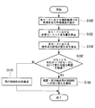
- FIG. 2 is a flowchart showing a flow of processing of a switching necessity determination program executed by the switching necessity determination unit 24 when the switching necessity determination process is executed.
- the switching necessity determination program is stored in the storage unit 25. Is remembered.
- trim angle of attack ⁇ t the trim speed v, the air density ⁇ in the trim flight condition, and the like are obtained from the sensor 2 or a database of trim calculation results performed in advance stored in the storage unit 25.
- Aircraft weight W, representative area S, inertia performance factors I XX , I YY , I ZZ , inertial product I ZX, and the like are stored in the storage unit 25 as a body specification database of the aircraft 1. Further, each aerodynamic coefficient is stored in the storage unit 25 as an aerodynamic database.
- step 100 based on the response model indicating the motion characteristics (mode) of the aircraft 1, the angular velocity and angular acceleration around the aircraft axis of the aircraft 1 are calculated.
- the angular velocity around the body axis is expressed by equation (3)
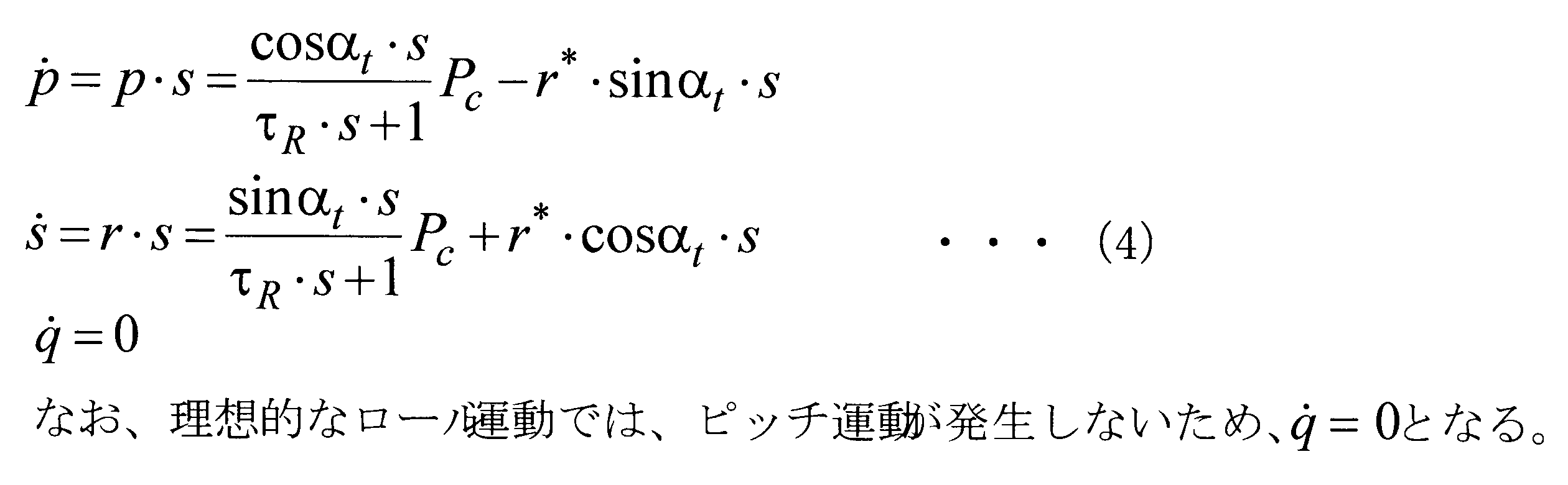
- the angular acceleration around the body axis is expressed by equation (4). Then, for example, by substituting the necessary minimum flight characteristic value (roll mode time constant ⁇ R in the roll mode) and equation (2) into the equations (3) and (4), the angular velocity around the aircraft axis is calculated. And the angular acceleration is calculated.
- the minimum necessary flight characteristic value is stored in the storage unit 25.
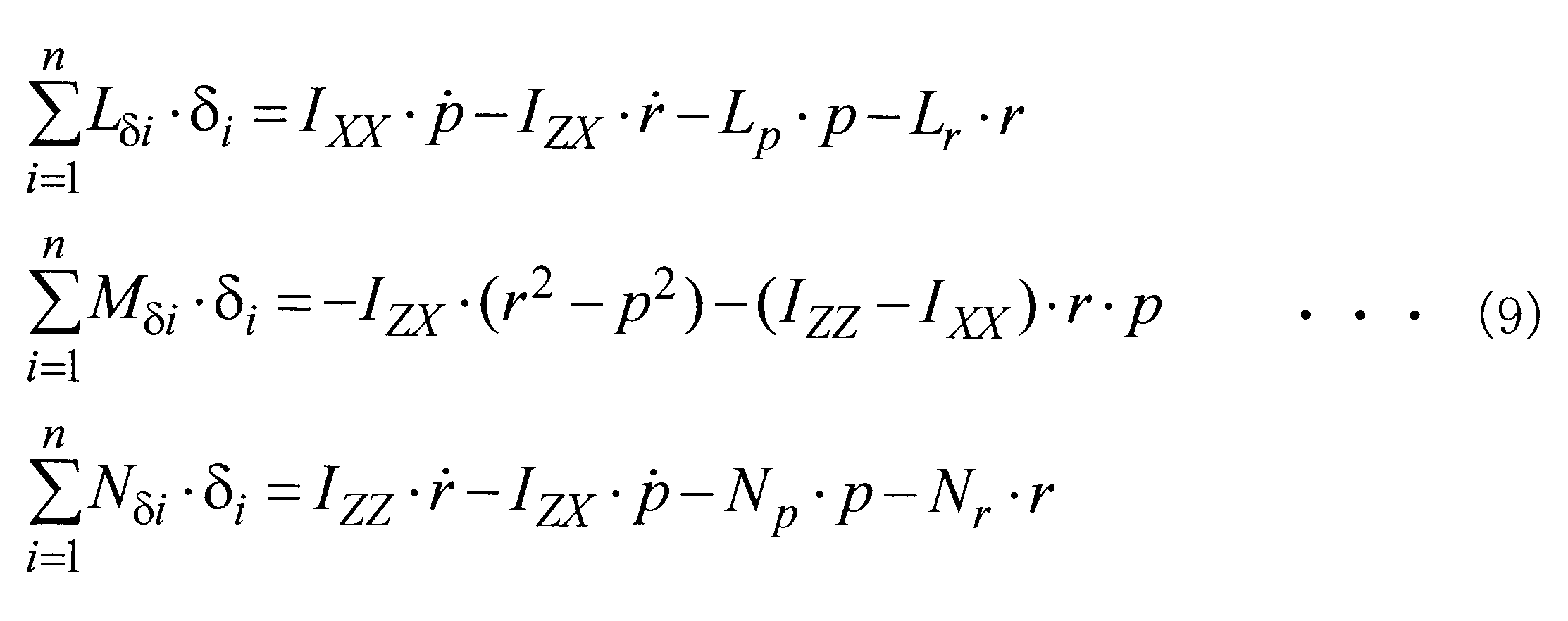
- the required moment change amount is calculated based on the nonlinear equation of motion related to the rotation of the aircraft 1.
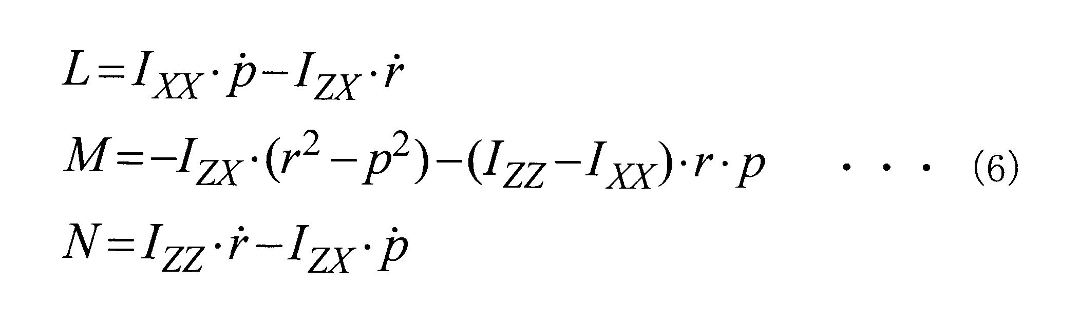
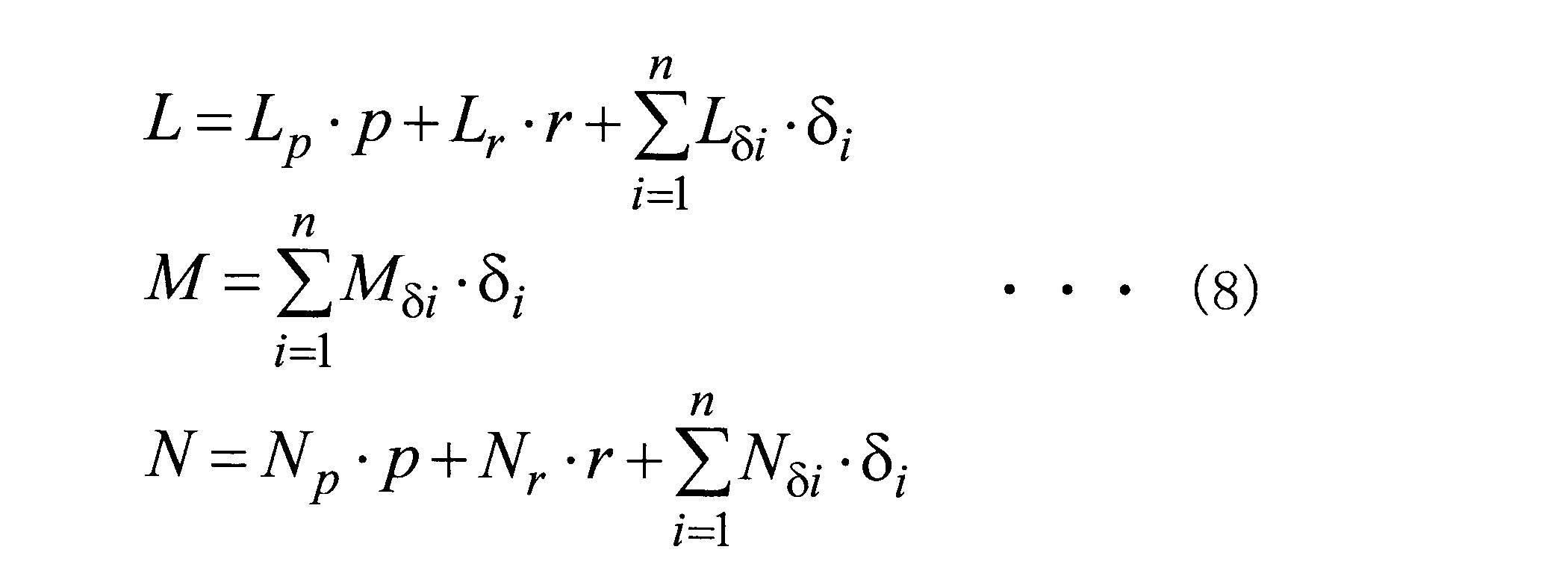
- the nonlinear motion equation relating to the rotation of the aircraft 1 is expressed by the equation (5) as external forces L, M, and N.
- Equation (7) the external forces L, M, and N are expressed by Equation (7) using a dimensional aerodynamic coefficient.
- equation (7) is expressed as equation (8).
- the rudder angle and the rate of change of the rudder angle are calculated.
- Equation (12) the matrix included in the left side of the equation (10) is the steering effect matrix B, and the right side of the equation (10) is F, so that each steering angle is calculated. Equation (12) is obtained. Note that B T (B ⁇ B T ) ⁇ 1 on the left side shown in the equation (12) is the optimum steering angle distribution rule.
- step 104 the response time history of each steering angle is calculated by substituting the time history of the angular velocity calculated by equation (3) and the time history of angular acceleration calculated by equation (4) into equation (12). To do. Further, in step 104, the change rate of each rudder angle is calculated by numerically differentiating the calculated response time history of each rudder angle.
- the rudder effectiveness aerodynamic coefficients (roll rudder effect L ⁇ i , pitch rudder effect M ⁇ i , yaw rudder effect N ⁇ i ) used in the equation (12) are obtained from the detection result of the control surface failure damage detection device 18, and
- the stability aerodynamic coefficients (roll damping L p , yaw rate roll effectiveness L r , direction stability N ⁇ , yaw damping N r ) are obtained from the aerodynamic database stored in the storage unit 25.
- step 106 it is determined whether or not the rudder angle or the change rate of the rudder angle calculated in step 104 exceeds a changeable range. If the determination is affirmative, the process proceeds to step 108, and the determination is negative. Shifts to step 110. That is, in step 106, in the case where a malfunction of the control surface 3 occurs, is it possible to realize a flight based on the minimum required flight characteristic value by controlling the control angle of the control surface 3 (flight control law 20)? Determine whether or not.
- the changeable range is specifically the operating range and maximum change rate of the rudder angle, and is specified by the characteristic value of the actuator 16 for driving the control surface 3.
- the characteristic value of the actuator 16 and the changeable range are stored in the storage unit 25 in advance.
- step 108 the display warning unit 12 is notified of a warning for prompting the operator to switch from the flight control law 20 to the control surface / thrust integrated flight control law 22, and the program ends.
- the operator of the aircraft 1 recognizes the malfunction of the control surface 3.
- the operator operates the switching unit 13 in order to switch from the flight control law 20 to the control surface / thrust integrated flight control law 22.
- the switching unit 13 outputs a switching command signal when operated.
- the computer 15 drives the switching processing unit 19 based on the switching command signal to switch the control law of the aircraft 1 from the flight control law 20 to the control surface / thrust integrated flight control law 22 and control surface / thrust integrated flight control.
- the aircraft 1 is controlled based on the rule 22.
- step 110 the flight control law 20 is reconfigured so as not to use the control surface 3 in which the malfunction is detected or to reduce the level of use, thereby addressing the malfunction of the control surface 3.
- the control system 6 controls the aircraft 1 by the reconfigured flight control law 20.
- control system 6 of the aircraft 1 may calculate the required moment change amount of the aircraft 1 in consideration of the effect of the gyro moment of the engine 4. Thereby, the rudder angle and the change rate of the rudder angle necessary for realizing each mode of the aircraft 1 can be calculated with higher accuracy.
- the fuselage shape of the aircraft 1 is changed. Since the change of the aerodynamic coefficient to be performed cannot be grasped in advance, the dynamic stable aerodynamic coefficient (roll damping L p , yaw rate roll effectiveness L r , directional stability N ⁇ , yaw detected by the control surface failure damage detection device 18 is not possible.
- the required moment change amount may be calculated using the damping N r ).
- the control system 6 of the aircraft 1 controls the flight control law 20 for controlling flight by controlling the rudder angle of the control surface 3, the rudder angle of the control surface 3, and the engine thrust.
- the control surface / thrust integrated flight control law 22 for controlling the flight by controlling the flight 15 and the control surface failure detection device 18 for detecting that at least one of the control surfaces 3 is malfunctioning. Is provided.
- the control system 6 realizes desired flight characteristics based on the detection result by the control surface failure / damage detection device 18 when the control surface failure / damage detection device 18 detects a malfunction of the control surface 3.
- control system 6 of the aircraft 1 can appropriately switch from the flight control law 20 to the control surface / thrust integrated flight control law 22.
- the control system 6 of the aircraft 1 is a case where a malfunction of the control surface 3 is detected by the control surface failure / damage detection device 18, and the calculated control angle or the change rate of the control angle changes.
- the flight control law 20 is reconfigured so that the control surface 3 in which a malfunction is detected is not used or the degree of use is reduced if the possible range is not exceeded. Switching to the thrust integrated flight control law 22 can be suppressed.
- the control law of the fuselage is switched from the flight control law 20 to the control surface / thrust integrated flight control law 22. Only in some cases is the control law switched.
- control system 6 of the aircraft 1 calculates the required moment change amount of the aircraft 1 from the angular velocity and angular acceleration around the body axis of the aircraft 1 calculated based on the response model indicating the motion characteristics of the aircraft. Since the rudder angle and the rate of change of the rudder angle satisfying the calculated required moment change amount are calculated, the rudder angle necessary for realizing various aircraft modes such as the roll mode, the Dutch roll mode, and the vertical short cycle mode, and The change rate of the steering angle can be easily calculated.
- the roll mode of the aircraft 1 has been described by taking the switching necessity determination process as an example.
- the present invention is not limited to this, and, for example, the Dutch roll of the aircraft 1 is not limited thereto.
- the rudder angle of the control surface 3 and the rate of change of the rudder angle may be calculated based on the transfer function corresponding to each mode.
- the steering angle is calculated by calculating the angular velocity and the angular acceleration around the body axis based on the transfer function indicating the ideal response of the side slip angle ⁇ in the Dutch roll mode.
- the rate of change of the rudder angle is calculated.
- the change in rudder angle and rudder angle is calculated by calculating the angular velocity and angular acceleration around the body axis based on the transfer function indicating the ideal response of the vertical load multiple and angle of attack. Calculate the rate.
- FIG. 3 is a flowchart showing a processing flow of the switching necessity determination program in the present modification. 3 that are the same as or similar to those in FIG. 2 are denoted by the same reference numerals as those in FIG.
- step 100 ′ the angular velocity and acceleration around the body axis of the aircraft 1 in each mode are calculated based on the response model indicating the roll mode, the Dutch roll mode, and the longitudinal short cycle mode of the aircraft 1.
- step 104 ' the steering angle and the rate of change of the steering angle in each mode are calculated.
- the rudder angle calculated in step 104 ′ or the change rate of the rudder angle is a range that can be changed in at least one of the roll mode, the Dutch roll mode, and the vertical short cycle mode. If it is determined positive, the process proceeds to step 108. If the determination is negative, the process proceeds to step 110.
- step 108 the display warning unit 12 is notified of a warning for prompting the operator to switch from the flight control law 20 to the control surface / thrust integrated flight control law 22, and the program ends.
- step 110 the flight control law 20 is reconfigured so that the control surface 3 in which the malfunction is detected is not used or the degree of use is reduced, so that the program is executed in response to the malfunction of the control surface 3. finish.
- the display warning unit 12 warns the driver and integrates the control surface and thrust from the flight control law 20.
- the present invention is not limited to this.
- the control system 6 automatically controls the flight without operating the switching unit 13 by the operator. It is good also as a form switched from the law 20 to the control surface / thrust integrated flight control law 22.
Landscapes
- Engineering & Computer Science (AREA)
- Aviation & Aerospace Engineering (AREA)
- Automation & Control Theory (AREA)
- Radar, Positioning & Navigation (AREA)
- Remote Sensing (AREA)
- Physics & Mathematics (AREA)
- General Physics & Mathematics (AREA)
- Control Of Position, Course, Altitude, Or Attitude Of Moving Bodies (AREA)
- Feedback Control In General (AREA)
- Aerodynamic Tests, Hydrodynamic Tests, Wind Tunnels, And Water Tanks (AREA)
Abstract
Description
しかしながら、舵面・推力統合飛行制御則は、エンジン推力も飛行制御に用いることから航空機の運動の応答が遅くなるため、可能な限り再構成可能な飛行制御則を用いて航空機の制御を継続する方が望ましく、再構成可能な飛行制御則から舵面・推力統合飛行制御則への切り替えは、適切に行われるべきものである。
また、第2制御則は、飛行の制御にエンジン推力も用いるため、第1制御則に比べて航空機の運動の応答が遅くなる。
そして、判定手段によって、算出手段で算出された舵角又は舵角の変化率が変化可能な範囲を超えているか否かが判定されることによって、第1制御則から第2制御則への切り替えの要否が判定される。
図1は、本実施形態に係る航空機の制御システムを適用した航空機1の概略構成を示したブロック図である。航空機1は、センサ2、舵面3、エンジン4、操縦室5、制御システム6を備えている。
なお、上記各演算器により候補値を算出するための各手法に基づく具体的な演算式等は、例えば、社団法人日本航空宇宙学会のシンポジウム等において、本発明の発明者によって既に発表されており(参考文献番号:JSASS-2009-5057)、公知であるのでここでの説明は省略する。
なお、記憶部25は、半導体記憶装置又は磁気記憶装置であり、切替要否判定処理に要する各種データ(航空機1に関する空力データベースや航空機1の機体諸元データベース等)を記憶している。
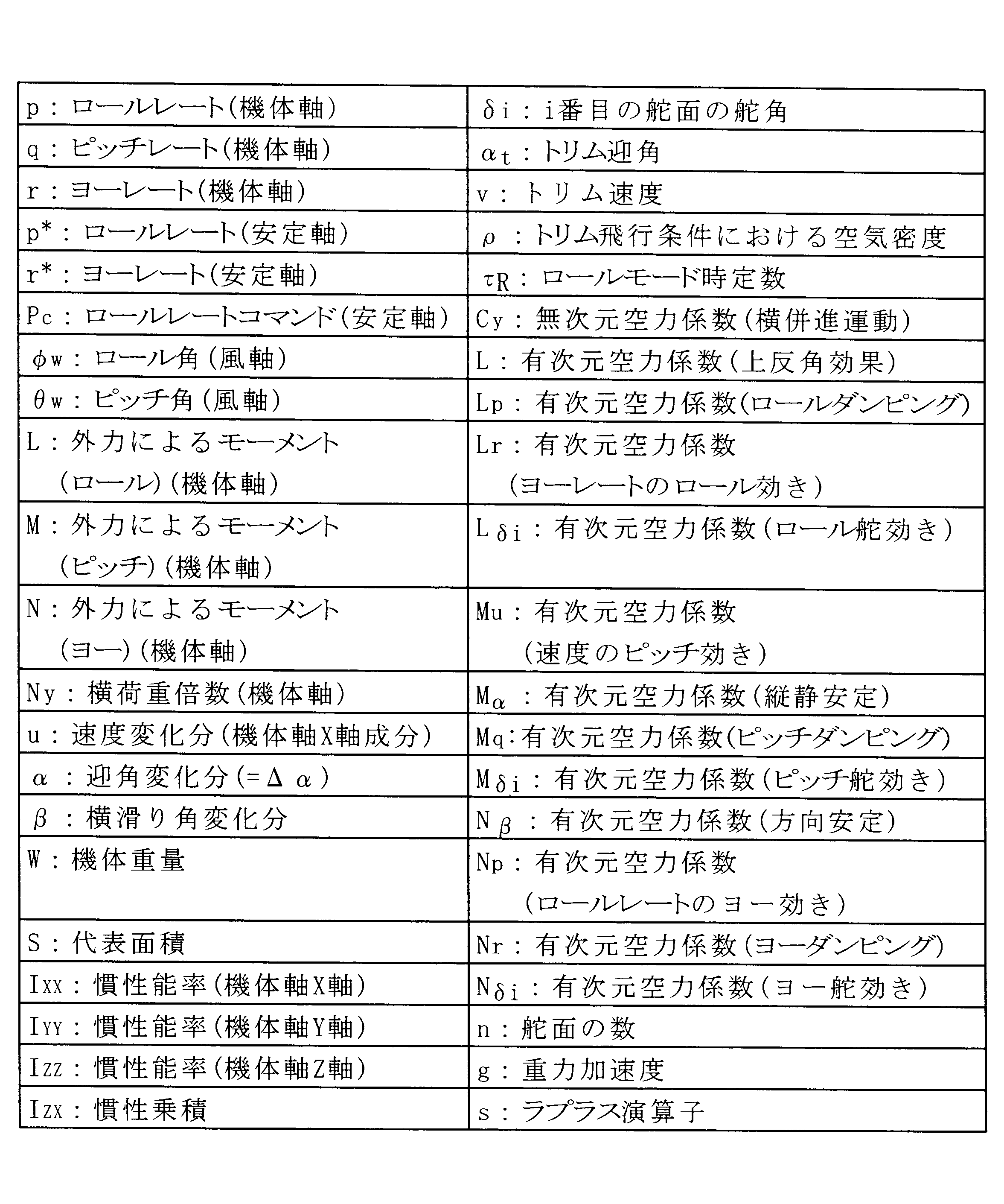
また、機体重量W、代表面積S、慣性能率IXX,IYY,IZZ、慣性乗積IZX等は、航空機1の機体諸元データベースとして記憶部25に記憶されている。さらに、各空力係数は、空力データベースとして記憶部25に記憶されている。


さらに、ステップ104では、上記算出した各舵角の応答時歴を数値微分することで、各舵角の変化率を算出する。
なお、上記変化可能な範囲とは、具体的には、舵角の作動範囲及び最大変化率であり、舵面3を駆動するためのアクチュエータ16の特性値によって、特定されるものである。アクチュエータ16の特性値及び上記変化可能な範囲は、記憶部25に予め記憶されている。
飛行制御則20の再構成が行われた場合、制御システム6は、再構成された飛行制御則20によって、航空機1の制御を行う。


上記実施形態では、切替要否判定処理を一例として、航空機1のロールモードについて説明したが、本発明は、これに限定されるものではなく、本変形例のように、例えば航空機1のダッチロールモードや縦短周期モード等他のモードについても、各モードに応じた伝達関数に基づいて舵面3の舵角及び舵角の変化率を算出してもよい。
2 センサ
3 舵面
4 エンジン
5 操縦室
6 制御システム
10 操縦端
12 表示警告部
13 切替部
15 コンピュータ
16 アクチュエータ
17 エンジン制御装置
18 舵面故障損傷検出装置
19 スイッチ
20 飛行制御則
22 舵面・推力統合飛行制御則
23 応答調整用フィルタ
24 切替要否判定部
25 記憶部
Claims (7)
- 舵面の舵角を制御することによって飛行を制御する第1制御則、前記舵面の舵角及びエンジン推力を制御することによって飛行を制御する第2制御則の何れかで飛行を制御する制御手段と、
前記舵面の少なくとも1つが機能不良であることを検出する舵面故障損傷検出手段と、
前記舵面故障損傷検出手段によって前記舵面の機能不良が検出された場合に、前記舵面故障損傷検出手段による検出結果に基づいて、所望の飛行特性を実現するために要する前記舵角及び前記舵角の変化率を算出する算出手段と、
前記算出手段によって算出された前記舵角又は前記舵角の変化率が変化可能な範囲を超えているか否かを判定することによって、前記第1制御則から前記第2制御則への切り替えの要否を判定する判定手段と、
を備えた航空機の制御システム。 - 前記制御手段は、前記舵面故障損傷検出手段によって前記舵面の機能不良が検出された場合であって、前記算出手段によって算出された前記舵角又は前記舵角の変化率が変化可能な範囲を超えていない場合に、前記舵面故障損傷検出手段によって機能不良が検出された前記舵面を使用しない又は使用の程度を低くするように、前記第1制御則を再構成し、前記算出手段によって算出された前記舵角又は前記舵角の変化率が変化可能な範囲を超えた場合に、前記第1制御則から前記第2制御則へ切り替える請求項1記載の航空機の制御システム。
- 前記算出手段は、航空機の運動特性を示す応答モデルに基づいて算出した航空機の機体軸周りの角速度及び角加速度から、航空機の必要モーメント変化量を算出し、算出した必要モーメント変化量を満たす前記舵角及び前記舵角の変化率を算出する請求項1又は請求項2記載の航空機の制御システム。
- 前記算出手段は、航空機の必要モーメント変化量を、エンジンのジャイロモーメントの効果を加味して算出する請求項3記載の航空機の制御システム。
- 請求項1乃至請求項4の何れか1項に記載の航空機の制御システムを備えた航空機。
- 舵面の舵角を制御することによって飛行を制御する第1制御則、前記舵面の舵角及びエンジン推力を制御することによって飛行を制御する第2制御則の何れかで飛行を制御する制御手段と、前記舵面の少なくとも1つが機能不良であることを検出する舵面故障損傷検出手段と、を備えた航空機の制御プログラムであって、
コンピュータを、
前記舵面故障損傷検出手段によって前記舵面の機能不良が検出された場合に、前記舵面故障損傷検出手段による検出結果に基づいて、所望の飛行特性を実現するために要する前記舵角及び前記舵角の変化率を算出する算出手段及び、
前記算出手段によって算出された前記舵角又は前記舵角の変化率が変化可能な範囲を超えているか否かを判定することによって、前記第1制御則から前記第2制御則への切り替えの要否を判定する判定手段と、
して機能させるための航空機の制御プログラム。 - 舵面の舵角を制御することによって飛行を制御する第1制御則、前記舵面の舵角及びエンジン推力を制御することによって飛行を制御する第2制御則の何れかで飛行を制御する制御手段と、前記舵面の少なくとも1つが機能不良であることを検出する舵面故障損傷検出手段と、を備えた航空機の制御方法であって、
前記舵面故障損傷検出手段によって前記舵面の機能不良が検出された場合に、前記舵面故障損傷検出手段による検出結果に基づいて、所望の飛行特性を実現するために要する前記舵角及び前記舵角の変化率を算出する第1工程と、
前記第1工程によって算出された前記舵角又は前記舵角の変化率が変化可能な範囲を超えているか否かを判定することによって、前記第1制御則から前記第2制御則への切り替えの要否を判定する第2工程と、
を含む航空機の制御方法。
Priority Applications (6)
| Application Number | Priority Date | Filing Date | Title |
|---|---|---|---|
| EP12757207.1A EP2687438B1 (en) | 2011-03-14 | 2012-03-08 | Control system of aircraft, aircraft, control program for aircraft, and control method for aircraft |
| CA2828444A CA2828444C (en) | 2011-03-14 | 2012-03-08 | Aircraft control system, aircraft, aircraft control program, and method for controlling aircraft |
| RU2013139093/11A RU2561168C2 (ru) | 2011-03-14 | 2012-03-08 | Система управления самолетом, самолет и способ управления самолетом |
| US14/001,765 US9199723B2 (en) | 2011-03-14 | 2012-03-08 | Aircraft control system, aircraft, aircraft control program, and method for controlling aircraft |
| CN201280010052.6A CN103391880B (zh) | 2011-03-14 | 2012-03-08 | 航空器的控制系统、航空器、航空器的控制程序及航空器的控制方法 |
| BR112013021765A BR112013021765A2 (pt) | 2011-03-14 | 2012-03-08 | sistema de controle de aeronave, aeronave, programa de controle de aeronave e método para o controle de aeronave |
Applications Claiming Priority (2)
| Application Number | Priority Date | Filing Date | Title |
|---|---|---|---|
| JP2011055320A JP5812633B2 (ja) | 2011-03-14 | 2011-03-14 | 航空機の制御システム、航空機、航空機の制御プログラム、及び航空機の制御方法 |
| JP2011-055320 | 2011-03-14 |
Publications (1)
| Publication Number | Publication Date |
|---|---|
| WO2012124594A1 true WO2012124594A1 (ja) | 2012-09-20 |
Family
ID=46830667
Family Applications (1)
| Application Number | Title | Priority Date | Filing Date |
|---|---|---|---|
| PCT/JP2012/055943 WO2012124594A1 (ja) | 2011-03-14 | 2012-03-08 | 航空機の制御システム、航空機、航空機の制御プログラム、及び航空機の制御方法 |
Country Status (8)
| Country | Link |
|---|---|
| US (1) | US9199723B2 (ja) |
| EP (1) | EP2687438B1 (ja) |
| JP (1) | JP5812633B2 (ja) |
| CN (1) | CN103391880B (ja) |
| BR (1) | BR112013021765A2 (ja) |
| CA (1) | CA2828444C (ja) |
| RU (1) | RU2561168C2 (ja) |
| WO (1) | WO2012124594A1 (ja) |
Cited By (4)
| Publication number | Priority date | Publication date | Assignee | Title |
|---|---|---|---|---|
| EP2869155A1 (en) * | 2013-08-30 | 2015-05-06 | Rosemount Aerospace Inc. | Flutter control actuator |
| CN106094853A (zh) * | 2016-06-29 | 2016-11-09 | 北京航空航天大学 | 一种上面级轨道转移段矢量推力的控制方法 |
| CN109703780A (zh) * | 2018-10-26 | 2019-05-03 | 中国飞行试验研究院 | 一种电传运输类飞机飞行试验舵面卡阻实现方法 |
| CN117784833A (zh) * | 2024-02-23 | 2024-03-29 | 四川腾盾科技有限公司 | 一种面对称飞行器速度控制系统、方法、设备及介质 |
Families Citing this family (31)
| Publication number | Priority date | Publication date | Assignee | Title |
|---|---|---|---|---|
| JP5893890B2 (ja) * | 2011-10-18 | 2016-03-23 | 三菱重工業株式会社 | 航空機及び航空機の制御方法 |
| KR102091003B1 (ko) * | 2012-12-10 | 2020-03-19 | 삼성전자 주식회사 | 음성인식 기술을 이용한 상황 인식 서비스 제공 방법 및 장치 |
| US8949090B2 (en) * | 2013-01-28 | 2015-02-03 | The Boeing Company | Formation flight control |
| US8878700B2 (en) * | 2013-02-18 | 2014-11-04 | The Boeing Company | Aircraft monitoring system |
| US9821903B2 (en) * | 2014-07-14 | 2017-11-21 | The Boeing Company | Closed loop control of aircraft control surfaces |
| US10401875B2 (en) * | 2014-07-31 | 2019-09-03 | The Boeing Company | Electronic stopper in actuator control |
| US9704407B2 (en) * | 2015-01-21 | 2017-07-11 | Honeywell International Inc. | Aircraft systems and methods with enhanced NOTAMs |
| US9703293B2 (en) * | 2015-08-31 | 2017-07-11 | The Boeing Company | Aircraft stall protection system |
| US10043402B1 (en) * | 2015-09-04 | 2018-08-07 | Rockwell Collins, Inc. | Flight path cross check |
| CN105109671B (zh) * | 2015-09-25 | 2017-05-17 | 江西洪都航空工业集团有限责任公司 | 一种前缘襟翼控制方法 |
| US9701418B2 (en) | 2015-10-06 | 2017-07-11 | Honeywell International Inc. | Pilot fatigue detection system and method from aircraft control device movement |
| CN105676853B (zh) * | 2016-01-15 | 2018-11-02 | 中国人民解放军国防科学技术大学 | 一种无人机中立位置自动调整的飞行控制方法 |
| CN113311878B (zh) * | 2016-05-31 | 2024-09-10 | 深圳市大疆灵眸科技有限公司 | 用于自适应云台的方法和系统 |
| US10005561B2 (en) * | 2016-06-16 | 2018-06-26 | Ge Aviation Systems Llc | Controlling aircraft using thrust differential trim |
| WO2018023492A1 (zh) * | 2016-08-03 | 2018-02-08 | 深圳市大疆灵眸科技有限公司 | 一种云台控制方法及系统 |
| WO2018061280A1 (ja) * | 2016-09-28 | 2018-04-05 | 株式会社Subaru | 飛行制限設定システム、飛行制限設定方法及び飛行制限設定プログラム |
| FR3057370B1 (fr) * | 2016-10-11 | 2019-08-23 | Airbus Operations | Procede et systeme de commande de vol d'un aeronef. |
| WO2018217210A1 (en) * | 2017-05-26 | 2018-11-29 | Sikorsky Aircraft Corporation | Adaptive control of aircraft using structural health monitoring |
| FR3072475B1 (fr) * | 2017-10-17 | 2019-11-01 | Thales | Procede de traitement d'une erreur lors de l'execution d'une procedure avionique predeterminee, programme d'ordinateur et systeme de detection et d'alerte associe |
| CN107728634B (zh) * | 2017-10-30 | 2021-04-30 | 刘先涛 | 用于控制飞机着陆的飞行控制方法及系统 |
| CN108033025B (zh) * | 2017-11-30 | 2021-05-14 | 陶文英 | 一种航空发动机推力控制系统 |
| CN107966992B (zh) * | 2018-01-11 | 2021-02-05 | 中国运载火箭技术研究院 | 一种重复使用运载器控制重构方法和系统 |
| US20190283862A1 (en) * | 2018-03-16 | 2019-09-19 | Honeywell International Inc. | Flight control system |
| US11094327B2 (en) * | 2018-09-28 | 2021-08-17 | Lenovo (Singapore) Pte. Ltd. | Audible input transcription |
| US11556758B2 (en) | 2019-08-27 | 2023-01-17 | International Business Machines Corporation | Learning approximate translations of unfamiliar measurement units during deep question answering system training and usage |
| US11475339B2 (en) * | 2019-08-30 | 2022-10-18 | International Business Machines Corporation | Learning unfamiliar measurement units in a deep question answering system |
| CN112373704A (zh) * | 2020-11-17 | 2021-02-19 | 中国商用飞机有限责任公司 | 通过控制发动机推力来实现飞机的应急控制的系统及飞机 |
| CN113625732B (zh) * | 2021-07-31 | 2024-07-05 | 西北工业大学 | 基于角加速度估计的增量反馈逆角速度控制律设计方法 |
| CN113959279B (zh) * | 2021-10-14 | 2023-08-22 | 北京理工大学 | 一种利用多传感器信息融合的弹道环境特征辨识方法 |
| CN115657729B (zh) * | 2022-12-27 | 2023-03-10 | 北京航空航天大学 | 一种考虑探测任务约束的无人机边界保护控制方法 |
| CN115930698B (zh) * | 2023-01-10 | 2024-08-27 | 中国人民解放军国防科技大学 | 一种非零滚转角条件下控制通道舵偏角转化为x形舵偏角的方法 |
Citations (5)
| Publication number | Priority date | Publication date | Assignee | Title |
|---|---|---|---|---|
| JPH06336199A (ja) * | 1993-05-28 | 1994-12-06 | Mitsubishi Heavy Ind Ltd | 航空機用部材損傷検出装置 |
| JPH08136199A (ja) * | 1994-11-14 | 1996-05-31 | Tech Res & Dev Inst Of Japan Def Agency | 双操舵飛しょう体の制御装置 |
| JP2003175896A (ja) * | 2001-12-10 | 2003-06-24 | Mitsubishi Heavy Ind Ltd | 舵面の故障・損傷検出装置 |
| JP2003291893A (ja) * | 2002-04-03 | 2003-10-15 | Mitsubishi Heavy Ind Ltd | 制御システム、航空機・宇宙機の飛行制御システム、車両の運動制御システム |
| JP3643870B2 (ja) * | 2002-02-12 | 2005-04-27 | 防衛庁技術研究本部長 | 故障、損傷耐性を有する再構成飛行制御システム |
Family Cites Families (9)
| Publication number | Priority date | Publication date | Assignee | Title |
|---|---|---|---|---|
| US3829838A (en) * | 1970-11-05 | 1974-08-13 | Battelle Development Corp | Computer-controlled three-dimensional pattern generator |
| US5330131A (en) * | 1992-05-28 | 1994-07-19 | The United States Of America As Represented By The Administrator Of National Aeronautics And Space Administration | Engines-only flight control system |
| JPH10167194A (ja) * | 1996-12-12 | 1998-06-23 | Mitsubishi Heavy Ind Ltd | 操縦舵面損傷検出機能を有する飛行制御装置 |
| US6102330A (en) | 1997-07-29 | 2000-08-15 | The United States Of America As Represented By The Administrator Of The National Aeronautics And Space Administration | Emergency multiengine aircraft system for lateral control using differential thrust control of wing engines |
| RU22564U1 (ru) * | 2001-09-05 | 2002-04-10 | Федеральное государственное унитарное предприятие Летно-исследовательский институт им. М.М. Громова | Система автоматического управления |
| US8016243B2 (en) * | 2006-10-12 | 2011-09-13 | The Boeing Company | Aircraft backup control |
| JP5123964B2 (ja) * | 2010-02-26 | 2013-01-23 | 三菱重工業株式会社 | 航空機の制御システム、航空機の制御方法、及び航空機 |
| JP5811604B2 (ja) * | 2011-06-08 | 2015-11-11 | セイコーエプソン株式会社 | 表示装置 |
| JP5811605B2 (ja) * | 2011-06-08 | 2015-11-11 | セイコーエプソン株式会社 | 表示装置 |
-
2011
- 2011-03-14 JP JP2011055320A patent/JP5812633B2/ja active Active
-
2012
- 2012-03-08 CA CA2828444A patent/CA2828444C/en not_active Expired - Fee Related
- 2012-03-08 WO PCT/JP2012/055943 patent/WO2012124594A1/ja active Application Filing
- 2012-03-08 BR BR112013021765A patent/BR112013021765A2/pt active Search and Examination
- 2012-03-08 CN CN201280010052.6A patent/CN103391880B/zh not_active Expired - Fee Related
- 2012-03-08 EP EP12757207.1A patent/EP2687438B1/en not_active Not-in-force
- 2012-03-08 RU RU2013139093/11A patent/RU2561168C2/ru active
- 2012-03-08 US US14/001,765 patent/US9199723B2/en active Active
Patent Citations (5)
| Publication number | Priority date | Publication date | Assignee | Title |
|---|---|---|---|---|
| JPH06336199A (ja) * | 1993-05-28 | 1994-12-06 | Mitsubishi Heavy Ind Ltd | 航空機用部材損傷検出装置 |
| JPH08136199A (ja) * | 1994-11-14 | 1996-05-31 | Tech Res & Dev Inst Of Japan Def Agency | 双操舵飛しょう体の制御装置 |
| JP2003175896A (ja) * | 2001-12-10 | 2003-06-24 | Mitsubishi Heavy Ind Ltd | 舵面の故障・損傷検出装置 |
| JP3643870B2 (ja) * | 2002-02-12 | 2005-04-27 | 防衛庁技術研究本部長 | 故障、損傷耐性を有する再構成飛行制御システム |
| JP2003291893A (ja) * | 2002-04-03 | 2003-10-15 | Mitsubishi Heavy Ind Ltd | 制御システム、航空機・宇宙機の飛行制御システム、車両の運動制御システム |
Non-Patent Citations (1)
| Title |
|---|
| See also references of EP2687438A4 * |
Cited By (7)
| Publication number | Priority date | Publication date | Assignee | Title |
|---|---|---|---|---|
| EP2869155A1 (en) * | 2013-08-30 | 2015-05-06 | Rosemount Aerospace Inc. | Flutter control actuator |
| US9611031B2 (en) | 2013-08-30 | 2017-04-04 | Rosemount Aerospace Inc. | Flutter control actuator |
| CN106094853A (zh) * | 2016-06-29 | 2016-11-09 | 北京航空航天大学 | 一种上面级轨道转移段矢量推力的控制方法 |
| CN109703780A (zh) * | 2018-10-26 | 2019-05-03 | 中国飞行试验研究院 | 一种电传运输类飞机飞行试验舵面卡阻实现方法 |
| CN109703780B (zh) * | 2018-10-26 | 2022-04-19 | 中国飞行试验研究院 | 一种电传运输类飞机飞行试验舵面卡阻实现方法 |
| CN117784833A (zh) * | 2024-02-23 | 2024-03-29 | 四川腾盾科技有限公司 | 一种面对称飞行器速度控制系统、方法、设备及介质 |
| CN117784833B (zh) * | 2024-02-23 | 2024-06-11 | 四川腾盾科技有限公司 | 一种面对称飞行器速度控制系统、方法、设备及介质 |
Also Published As
| Publication number | Publication date |
|---|---|
| EP2687438B1 (en) | 2016-06-08 |
| JP2012188065A (ja) | 2012-10-04 |
| EP2687438A4 (en) | 2015-01-14 |
| RU2013139093A (ru) | 2015-04-20 |
| US20130338859A1 (en) | 2013-12-19 |
| CN103391880B (zh) | 2015-12-09 |
| EP2687438A1 (en) | 2014-01-22 |
| CA2828444C (en) | 2016-02-16 |
| RU2561168C2 (ru) | 2015-08-27 |
| CN103391880A (zh) | 2013-11-13 |
| JP5812633B2 (ja) | 2015-11-17 |
| CA2828444A1 (en) | 2012-09-20 |
| BR112013021765A2 (pt) | 2016-10-18 |
| US9199723B2 (en) | 2015-12-01 |
Similar Documents
| Publication | Publication Date | Title |
|---|---|---|
| JP5812633B2 (ja) | 航空機の制御システム、航空機、航空機の制御プログラム、及び航空機の制御方法 | |
| US8352099B1 (en) | Varying engine thrust for directional control of an aircraft experiencing engine thrust asymmetry | |
| JP7544905B2 (ja) | 航空機制御システム及び方法 | |
| CN102695649B (zh) | 飞机的控制系统、飞机的控制方法以及飞机 | |
| CN110127041B (zh) | 用于旋翼飞行器自旋进入辅助的系统和方法 | |
| EP3620373B1 (en) | Stuck in detent monitors for collective and cyclic sticks | |
| US7463956B2 (en) | Constant vertical state maintaining cueing system | |
| US11599111B2 (en) | Reverse tactile cue for rotorcraft rotor overspeed protection | |
| US8002220B2 (en) | Rate limited active pilot inceptor system and method | |
| WO2008065664A2 (en) | Flight control cockpit modes in ducted fan vtol vehicles | |
| JP2016104614A (ja) | 水平尾翼荷重最適化のためのシステム及び方法 | |
| EP3546346B1 (en) | Rotorcraft with weight-on-wheels sensors and fcc (flight control computer) | |
| Ducard et al. | Modeling of an unmanned hybrid aerial vehicle | |
| CN109715494B (zh) | 驱动飞机空气动力学操纵面的致动器的开环和闭环控制 | |
| EP1528448B1 (en) | Aircraft multi-axis modal suppression system |
Legal Events
| Date | Code | Title | Description |
|---|---|---|---|
| 121 | Ep: the epo has been informed by wipo that ep was designated in this application |
Ref document number: 12757207 Country of ref document: EP Kind code of ref document: A1 |
|
| WWE | Wipo information: entry into national phase |
Ref document number: 2012757207 Country of ref document: EP |
|
| ENP | Entry into the national phase |
Ref document number: 2828444 Country of ref document: CA |
|
| WWE | Wipo information: entry into national phase |
Ref document number: 14001765 Country of ref document: US |
|
| NENP | Non-entry into the national phase |
Ref country code: DE |
|
| ENP | Entry into the national phase |
Ref document number: 2013139093 Country of ref document: RU Kind code of ref document: A |
|
| REG | Reference to national code |
Ref country code: BR Ref legal event code: B01A Ref document number: 112013021765 Country of ref document: BR |
|
| ENP | Entry into the national phase |
Ref document number: 112013021765 Country of ref document: BR Kind code of ref document: A2 Effective date: 20130826 |