WO2012124399A1 - 舶用エンジン制御装置および方法 - Google Patents
舶用エンジン制御装置および方法 Download PDFInfo
- Publication number
- WO2012124399A1 WO2012124399A1 PCT/JP2012/052316 JP2012052316W WO2012124399A1 WO 2012124399 A1 WO2012124399 A1 WO 2012124399A1 JP 2012052316 W JP2012052316 W JP 2012052316W WO 2012124399 A1 WO2012124399 A1 WO 2012124399A1
- Authority
- WO
- WIPO (PCT)
- Prior art keywords
- rotational speed
- fuel index
- engine control
- marine engine
- actual rotational
- Prior art date
- Legal status (The legal status is an assumption and is not a legal conclusion. Google has not performed a legal analysis and makes no representation as to the accuracy of the status listed.)
- Ceased
Links
Images



Classifications
-
- F—MECHANICAL ENGINEERING; LIGHTING; HEATING; WEAPONS; BLASTING
- F02—COMBUSTION ENGINES; HOT-GAS OR COMBUSTION-PRODUCT ENGINE PLANTS
- F02D—CONTROLLING COMBUSTION ENGINES
- F02D41/00—Electrical control of supply of combustible mixture or its constituents
- F02D41/02—Circuit arrangements for generating control signals
- F02D41/14—Introducing closed-loop corrections
-
- F—MECHANICAL ENGINEERING; LIGHTING; HEATING; WEAPONS; BLASTING
- F02—COMBUSTION ENGINES; HOT-GAS OR COMBUSTION-PRODUCT ENGINE PLANTS
- F02D—CONTROLLING COMBUSTION ENGINES
- F02D29/00—Controlling engines, such controlling being peculiar to the devices driven thereby, the devices being other than parts or accessories essential to engine operation, e.g. controlling of engines by signals external thereto
- F02D29/02—Controlling engines, such controlling being peculiar to the devices driven thereby, the devices being other than parts or accessories essential to engine operation, e.g. controlling of engines by signals external thereto peculiar to engines driving vehicles; peculiar to engines driving variable pitch propellers
-
- F—MECHANICAL ENGINEERING; LIGHTING; HEATING; WEAPONS; BLASTING
- F02—COMBUSTION ENGINES; HOT-GAS OR COMBUSTION-PRODUCT ENGINE PLANTS
- F02D—CONTROLLING COMBUSTION ENGINES
- F02D41/00—Electrical control of supply of combustible mixture or its constituents
- F02D41/02—Circuit arrangements for generating control signals
- F02D41/04—Introducing corrections for particular operating conditions
-
- F—MECHANICAL ENGINEERING; LIGHTING; HEATING; WEAPONS; BLASTING
- F02—COMBUSTION ENGINES; HOT-GAS OR COMBUSTION-PRODUCT ENGINE PLANTS
- F02D—CONTROLLING COMBUSTION ENGINES
- F02D41/00—Electrical control of supply of combustible mixture or its constituents
- F02D41/02—Circuit arrangements for generating control signals
- F02D41/14—Introducing closed-loop corrections
- F02D41/1401—Introducing closed-loop corrections characterised by the control or regulation method
-
- F—MECHANICAL ENGINEERING; LIGHTING; HEATING; WEAPONS; BLASTING
- F02—COMBUSTION ENGINES; HOT-GAS OR COMBUSTION-PRODUCT ENGINE PLANTS
- F02D—CONTROLLING COMBUSTION ENGINES
- F02D41/00—Electrical control of supply of combustible mixture or its constituents
- F02D41/02—Circuit arrangements for generating control signals
- F02D41/14—Introducing closed-loop corrections
- F02D41/1497—With detection of the mechanical response of the engine
-
- F—MECHANICAL ENGINEERING; LIGHTING; HEATING; WEAPONS; BLASTING
- F02—COMBUSTION ENGINES; HOT-GAS OR COMBUSTION-PRODUCT ENGINE PLANTS
- F02D—CONTROLLING COMBUSTION ENGINES
- F02D45/00—Electrical control not provided for in groups F02D41/00 - F02D43/00
-
- F—MECHANICAL ENGINEERING; LIGHTING; HEATING; WEAPONS; BLASTING
- F02—COMBUSTION ENGINES; HOT-GAS OR COMBUSTION-PRODUCT ENGINE PLANTS
- F02D—CONTROLLING COMBUSTION ENGINES
- F02D41/00—Electrical control of supply of combustible mixture or its constituents
- F02D41/02—Circuit arrangements for generating control signals
- F02D41/14—Introducing closed-loop corrections
- F02D41/1401—Introducing closed-loop corrections characterised by the control or regulation method
- F02D2041/1409—Introducing closed-loop corrections characterised by the control or regulation method using at least a proportional, integral or derivative controller
-
- F—MECHANICAL ENGINEERING; LIGHTING; HEATING; WEAPONS; BLASTING
- F02—COMBUSTION ENGINES; HOT-GAS OR COMBUSTION-PRODUCT ENGINE PLANTS
- F02D—CONTROLLING COMBUSTION ENGINES
- F02D41/00—Electrical control of supply of combustible mixture or its constituents
- F02D41/02—Circuit arrangements for generating control signals
- F02D41/14—Introducing closed-loop corrections
- F02D41/1401—Introducing closed-loop corrections characterised by the control or regulation method
- F02D2041/1413—Controller structures or design
- F02D2041/1431—Controller structures or design the system including an input-output delay
-
- F—MECHANICAL ENGINEERING; LIGHTING; HEATING; WEAPONS; BLASTING
- F02—COMBUSTION ENGINES; HOT-GAS OR COMBUSTION-PRODUCT ENGINE PLANTS
- F02D—CONTROLLING COMBUSTION ENGINES
- F02D31/00—Use of speed-sensing governors to control combustion engines, not otherwise provided for
- F02D31/001—Electric control of rotation speed
- F02D31/007—Electric control of rotation speed controlling fuel supply
-
- F—MECHANICAL ENGINEERING; LIGHTING; HEATING; WEAPONS; BLASTING
- F02—COMBUSTION ENGINES; HOT-GAS OR COMBUSTION-PRODUCT ENGINE PLANTS
- F02D—CONTROLLING COMBUSTION ENGINES
- F02D41/00—Electrical control of supply of combustible mixture or its constituents
- F02D41/0097—Electrical control of supply of combustible mixture or its constituents using means for generating speed signals
Definitions
- the present invention relates to a marine engine control device that controls the operation of a main engine of a marine vessel.
- the object of the present invention is to perform main engine control in which the propeller torque is constant, suppress thrust fluctuation, and improve propulsion efficiency.
- the marine engine control apparatus of the present invention is a marine engine control apparatus that outputs a fuel index by giving a target rotational speed, and feeds back a feedback signal that is delayed by 10% to 30% with respect to the fluctuation cycle of the actual rotational speed of the main engine.
- the fuel index is varied in proportion to the fluctuation angular velocity of the actual rotational speed.
- the feedback signal is, for example, a signal obtained by delaying the actual rotation speed with a time delay logic, and the deviation between the target rotation speed and the feedback signal is output via a proportional calculation unit in which a gain corresponding to the variable angular speed is set, for example. .
- a target rotational speed / fuel index conversion means for calculating a fuel index corresponding to the target rotational speed is further provided, and an output from the proportional calculation unit is added to the fuel index corresponding to the target rotational speed.
- the marine engine control device includes a PI control unit, and a deviation between the target rotation speed and the feedback signal is input to the PI control unit, and a fuel index corresponding to the target rotation speed is generated and generated in the I calculation unit of the PI control unit. Maintained.
- the feedback signal may be generated by differential calculation of the actual rotation speed.
- the ship of the present invention is characterized by including the marine engine control device.
- the marine engine control method of the present invention is a marine engine control method for providing a target rotational speed and outputting a fuel index, and providing a feedback signal delayed by 10% to 30% with respect to the fluctuation cycle of the actual rotational speed of the main engine. While returning, the fuel index is varied in proportion to the angular velocity of the actual rotational speed.
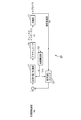
- FIG. 1 is a control block diagram showing the configuration of a marine engine control apparatus according to the first embodiment of the present invention.
- the marine engine control device 10 of this embodiment is a governor system that controls fuel supply to the main engine 11, and a crankshaft (not shown) of the main engine 11 is connected to a propeller (not shown) for propulsion. Is done.
- the target rotational speed No is set as the target value, and the actual rotational speed Ne that is the output of the main engine 11 is detected by a known method using a turning gear or the like.
- the target rotation speed No is converted into the fuel index FIo in the N / FI conversion unit 12.
- a deviation from the actual rotational speed Ne of the main engine 11 fed back via the time delay logic 13 is obtained, and a proportional calculation is performed in the proportional control unit 14.
- the proportional control unit 14 performs a proportional calculation with a gain proportional to the fluctuation angular velocity ⁇ of the actual rotational speed Ne, and the time delay logic 13 sets the phase of the actual rotational speed Ne to approximately 90 ° or about the fluctuation period. Delay 10-30%.
- the gain of the proportional control unit 14 and the delay time of the time delay logic 13 are determined based on the cycle T of the actual rotation speed Ne calculated by the cycle calculation unit 15 based on the fluctuation of the actual rotation speed Ne.
- signals from the N / FI conversion unit 12 and the proportional control unit 14 are added and input to the actuator 16, and the actuator 16 supplies the main engine 11 with an amount of fuel corresponding to the fuel index FI.
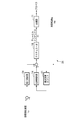
- FIG. 2 shows main engine rotation speed N (FIG. 2 (a)), fuel index FI or main engine torque Qe (FIG. 2 (b)), propeller torque Qp or thrust (in the constant fuel index control and constant propeller torque control).
- FIG. 2 (c)) shows the time variation of the torque coefficient Kq (FIG. 2 (d)) with the average value being 100%. Further, in FIG. 2, the fluctuation of each physical quantity in the fuel index constant control is shown in the section of 0 to 25 seconds, and the fluctuation of each physical quantity in the constant propeller torque control is shown in the section of 30 to 55 seconds.
- the propeller torque Qp, the torque coefficient Kq, and the main engine rotation speed N are calculated using the average values Qpa, Kqa, Na and the fluctuation components ⁇ Qp, ⁇ Kq, ⁇ N, respectively.
- load fluctuation due to disturbance such as waves is expressed as fluctuation ⁇ Kq of torque coefficient Kq, and ⁇ Kq is a sine wave of fluctuation angular velocity ⁇ (left of FIG. 2 (d)).
- ⁇ Kq A ⁇ sin ( ⁇ t) (7) (T is time), from equation (3):
- ⁇ Qp A ⁇ sin ( ⁇ t) + 2 ⁇ ⁇ N (8) It becomes.
- the main engine rotational speed N has a phase ⁇ delay corresponding to the moment of inertia I as shown in the equation (10). fluctuate.
- the thrust coefficient Kt fluctuates in substantially the same manner (in the same phase) as the torque coefficient Kq except for the difference in offset.
- the fuel index FI can be regarded as the main engine torque Qe. Therefore, when the load variation is given by the equation (7), the propeller torque Qp is kept constant by adding the variation of the equation (13) to the fuel index FIo corresponding to the target rotational speed No (FIG. 2 (c) )right). That is, in the first embodiment, as shown in FIG. 1, in the time delay logic 13, the phase obtained by delaying the phase of the actual rotational speed Ne by 90 ° (one quarter cycle) is negatively fed back, and the proportional control unit 14. Then, amplification is performed with a gain corresponding to the fluctuation angular velocity ⁇ .
- the propeller torque can be kept constant, the thrust can be kept constant, and the propulsion efficiency can be prevented from lowering due to load fluctuations.
- FIG. 3 is a control block diagram showing the configuration of the marine engine control device of the second embodiment.
- the marine engine control apparatus 10 of the first embodiment only the P control is used, and the fuel index FIo corresponding to the target rotational speed No is generated through the N / FI conversion unit 12.
- the marine engine control device 20 of the second embodiment PI control is used and the N / FI conversion unit 12 is not used.
- Other configurations are the same as those of the first embodiment, and the same reference numerals are used for the same configurations and the description thereof is omitted.
- the deviation between the target rotational speed No and the feedback signal of the actual rotational speed Ne via the time delay logic 13 is input to the proportional + integral control unit (PI control unit) 17.
- the input deviation is subjected to various calculations in the proportional + integral control unit (PI control unit) 17 and is output to the actuator 16.
- the fuel index FIo corresponding to the target rotational speed No is generated and maintained in the I calculation unit of the proportional + integral control unit (PI control unit) 17.
- the integration time constant is set to a longer time that is not affected by the fluctuation period.
- the propeller torque can be kept constant, and the same effect can be obtained.
- feedback is performed by delaying the actual rotational speed using the time delay logic, and the gain of the proportional calculation unit is set corresponding to the fluctuation angular speed of the actual rotational speed.
- a configuration may also be adopted in which a differential operation is performed on the rotational speed to feed back.
- FIGS. 4 and 5 show control block diagrams of the marine engine control devices 22 and 25 of the third and fourth embodiments using the differential operation.
- the same reference numerals are used for the same configurations as those in the first and second embodiments, and the description thereof is omitted.
- the fuel index FIo corresponding to the target rotational speed No is generated through the N / FI conversion unit 12, and the actual rotational speed Ne is determined by the N / FI via the differential operation logic 21 and the proportional control unit 14. Positive feedback is provided to the fuel index FIo from the converter 12.
- differential operation logic 21 differential operation is performed on the actual rotational speed Ne, and in the proportional control unit 14, the differential signal is amplified with a predetermined gain.
- the actual rotational speed Ne is positively fed back via the differential operation logic 21 and the proportional control unit 14 as in the third embodiment, and negatively fed back to the input side of the target rotational speed No.
- the deviation is input to the integration control unit 24. That is, the integration time constant of the integration control unit 24 is set to a longer time that is not affected by the fluctuation period, and the fuel index FIo corresponding to the target rotational speed No is generated and maintained in the I operation of the integration control unit 24. .
- the feedback signal output from the proportional control unit 14 is positively fed back to the signal FIo from the integration control unit 24, and the sum thereof is input to the actuator 16.
- the constant propeller torque control can be realized as in the first and second embodiments.
- the constant propeller torque control of the first to fourth embodiments is used in combination with, for example, constant rotation speed control, constant fuel index control, constant output control, and the like, and can be selectively switched automatically or manually according to sea conditions, for example.
- Propeller torque constant control is suitable when the load fluctuation due to waves or the like has a substantially constant cycle of about 20 seconds or less (more preferably 10 seconds or less), and is selected under such conditions, for example.
- the propeller torque constant control can be switched to the constant output control by setting the delay time of the time delay logic to 0 and setting the proportional gain of the control unit to 1.
Landscapes
- Engineering & Computer Science (AREA)
- Chemical & Material Sciences (AREA)
- Combustion & Propulsion (AREA)
- Mechanical Engineering (AREA)
- General Engineering & Computer Science (AREA)
- Electrical Control Of Air Or Fuel Supplied To Internal-Combustion Engine (AREA)
- Combined Controls Of Internal Combustion Engines (AREA)
- Control Of Vehicle Engines Or Engines For Specific Uses (AREA)
- Feedback Control In General (AREA)
Abstract
Description
11 主機関
12 N/FI変換部
13 時間遅れロジック
14 比例制御部
15 周期算出部
16 アクチュエータ
17 比例+積分制御部(PI制御部)
21 微分演算ロジック
24 積分制御部
図1は、本発明の第1実施形態である舶用エンジンの制御装置の構成を示す制御ブロック図である。
Qp=Kq・N2 (1)
と表される。
Qp=Qpa+△Qp
Kq=Kqa+△Kq
N =Na +△N
と表し、(1)式を平均値周りに線形近似すると
△Qp=(∂Qp/∂Kq)・△Kq+(∂Qp/∂N)・△N
=Na2・△Kq+2Kqa・Na・△N (2)
と近似できる。
△Qp=△Kq+2・△N (3)
と表わされる。
dN/dt=(Qe-Qp)/I (4)
となる。ここで主機トルクQeをその平均値Qeaおよび変動成分△Qeに分離し、Qe=Qea+△Qeで表すとき、Qeaは実質的にQpaに等しいので(Qea=Qpa)、(4)式は
d△N/dt=(△Qe-△Qp)/I (5)
と表される。
主機トルクQeは、フューエルインデックスFIに略正比例し、係数を除けば実質的にフューエルインデックスFIに等しいとおけるので、フューエルインデックス一定制御では、△Qe=0と考えることができる(図2(b)左)。このとき、(5)式は
d△N/dt=-△Qp/I (6)
と表される。
△Kq=A・sin(ωt) (7)
を仮定すると(tは時間)、(3)式から
△Qp=A・sin(ωt)+2・△N (8)
となる。これを(6)式に代入するとオイラーの運動方程式は、
d△N/dt=-(A・sin(ωt)+2・△N)/I (9)
となる。
△N=B・sin(ωt+θ) (10)
B=-A/√((ωI)2+4)
θ=-tan-1(ωI/2)
と表される(図2(a)左)。
一方、プロペラトルクQpが一定であれば、△Qp=0であり(図2(c)右)、これを(3)式に代入すると
△N=-△Kq/2 (11)
が得られる。すなわち平均値の周りで線形近似が成り立つとき、プロペラトルクQpを一定にするには、主機回転速度Nをトルク係数Kqの変動△Kqに合わせて目標回転速度Noを中心に(11)式にしたがって変動させればよい(図2(a)右)。
d△N/dt=△Qe/I
と表され、主機トルクQeの変動成分△Qeは
△Qe=I・(d△N/dt) (12)
となる。
△N=-A・sin(ωt)/2
となり、主機回転速度Nをトルク係数の変動△Kqとは逆位相で、1/2の振幅で変動させればよいことが分かる(図2(a)右)。また、これは(12)式から、主機トルクQeを平均値Qeaの周りに
△Qe=-ω・I・A・cos(ωt)/2 (13)
で変動させることに対応する(図2(b)右)。
Claims (7)
- 目標回転速度を与えフューエルインデックスを出力する舶用エンジン制御装置であって、主機関の実回転速度の変動周期に対して10%~30%遅延したフィードバック信号を帰還するとともに、前記実回転速度の変動角速度に比例して前記フューエルインデックスを変動させることを特徴とする舶用エンジン制御装置。
- 前記フィードバック信号が前記実回転速度を時間遅れロジックで遅延された信号であり、前記目標回転速度と前記フィードバック信号の偏差が前記変動角速度に対応するゲインが設定される比例演算部を介して出力されることを特徴とする請求項1に記載の舶用エンジン制御装置。
- 前記目標回転速度に対応するフューエルインデックスを算出する目標回転速度/フューエルインデックス変換手段を備え、前記比例演算部からの出力が、前記目標回転速度に対応するフューエルインデックスに加算されることを特徴とする請求項2に記載の舶用エンジン制御装置。
- PI制御部を備え、前記目標回転速度と前記フィードバック信号の偏差が前記PI制御部に入力され、前記目標回転速度に対応するフューエルインデックスが、前記PI制御部のI演算部において生成・維持されることを特徴とする請求項2に記載の舶用エンジン制御装置。
- 前記フィードバック信号が、前記実回転速度の微分演算により生成されることを特徴とする請求項1に記載の舶用エンジン制御装置。
- 請求項1~5の何れか一項に記載の舶用エンジン制御装置を備えることを特徴とする船舶。
- 目標回転速度を与えフューエルインデックスを出力する舶用エンジン制御方法であって、主機関の実回転速度の変動周期に対して10%~30%遅延したフィードバック信号を帰還するとともに、前記実回転速度の変動角速度に比例して前記フューエルインデックスを変動させることを特徴とする舶用エンジン制御方法。
Priority Applications (2)
| Application Number | Priority Date | Filing Date | Title |
|---|---|---|---|
| CN2012800016831A CN102959217A (zh) | 2011-03-15 | 2012-02-01 | 船舶用引擎控制装置及方法 |
| KR1020127028892A KR101229816B1 (ko) | 2011-03-15 | 2012-02-01 | 선박용 엔진 제어 장치 및 방법 |
Applications Claiming Priority (2)
| Application Number | Priority Date | Filing Date | Title |
|---|---|---|---|
| JP2011057022A JP4994505B1 (ja) | 2011-03-15 | 2011-03-15 | 舶用エンジン制御装置および方法 |
| JP2011-057022 | 2011-03-15 |
Publications (1)
| Publication Number | Publication Date |
|---|---|
| WO2012124399A1 true WO2012124399A1 (ja) | 2012-09-20 |
Family
ID=46793875
Family Applications (1)
| Application Number | Title | Priority Date | Filing Date |
|---|---|---|---|
| PCT/JP2012/052316 Ceased WO2012124399A1 (ja) | 2011-03-15 | 2012-02-01 | 舶用エンジン制御装置および方法 |
Country Status (5)
| Country | Link |
|---|---|
| JP (1) | JP4994505B1 (ja) |
| KR (1) | KR101229816B1 (ja) |
| CN (1) | CN102959217A (ja) |
| TW (1) | TW201239191A (ja) |
| WO (1) | WO2012124399A1 (ja) |
Families Citing this family (5)
| Publication number | Priority date | Publication date | Assignee | Title |
|---|---|---|---|---|
| JP7019369B2 (ja) * | 2017-10-11 | 2022-02-15 | ナブテスコ株式会社 | 遠隔制御装置 |
| JP6907139B2 (ja) * | 2018-02-27 | 2021-07-21 | 株式会社三井E&Sマシナリー | 舶用主機関の制御システム |
| CN109669347B (zh) * | 2018-12-05 | 2024-04-02 | 山东智翼航空科技有限公司 | 无人艇转速差动减摇增稳系统及方法 |
| JP7448415B2 (ja) * | 2020-01-28 | 2024-03-12 | ナブテスコ株式会社 | 燃料制御装置、及び舵制御装置 |
| CN112963254B (zh) * | 2021-03-23 | 2022-09-23 | 潍柴动力股份有限公司 | 一种发动机控制方法及发动机 |
Citations (3)
| Publication number | Priority date | Publication date | Assignee | Title |
|---|---|---|---|---|
| JPH08246937A (ja) * | 1995-03-08 | 1996-09-24 | Nissan Motor Co Ltd | ディーゼルエンジンの燃料噴射時期制御装置 |
| JP2002180876A (ja) * | 2000-12-07 | 2002-06-26 | Unisia Jecs Corp | 内燃機関の空燃比制御装置 |
| JP2010235049A (ja) * | 2009-03-31 | 2010-10-21 | Mitsui Eng & Shipbuild Co Ltd | 舶用動力システム |
Family Cites Families (1)
| Publication number | Priority date | Publication date | Assignee | Title |
|---|---|---|---|---|
| JPH05263687A (ja) * | 1992-03-23 | 1993-10-12 | Zexel Corp | 内燃機関の回転速度制御方法 |
-
2011
- 2011-03-15 JP JP2011057022A patent/JP4994505B1/ja not_active Expired - Fee Related
-
2012
- 2012-02-01 WO PCT/JP2012/052316 patent/WO2012124399A1/ja not_active Ceased
- 2012-02-01 KR KR1020127028892A patent/KR101229816B1/ko not_active Expired - Fee Related
- 2012-02-01 CN CN2012800016831A patent/CN102959217A/zh active Pending
- 2012-02-20 TW TW101105439A patent/TW201239191A/zh unknown
Patent Citations (3)
| Publication number | Priority date | Publication date | Assignee | Title |
|---|---|---|---|---|
| JPH08246937A (ja) * | 1995-03-08 | 1996-09-24 | Nissan Motor Co Ltd | ディーゼルエンジンの燃料噴射時期制御装置 |
| JP2002180876A (ja) * | 2000-12-07 | 2002-06-26 | Unisia Jecs Corp | 内燃機関の空燃比制御装置 |
| JP2010235049A (ja) * | 2009-03-31 | 2010-10-21 | Mitsui Eng & Shipbuild Co Ltd | 舶用動力システム |
Also Published As
| Publication number | Publication date |
|---|---|
| JP2012193641A (ja) | 2012-10-11 |
| TW201239191A (en) | 2012-10-01 |
| JP4994505B1 (ja) | 2012-08-08 |
| KR20120127678A (ko) | 2012-11-22 |
| CN102959217A (zh) | 2013-03-06 |
| KR101229816B1 (ko) | 2013-02-05 |
Similar Documents
| Publication | Publication Date | Title |
|---|---|---|
| JP4994505B1 (ja) | 舶用エンジン制御装置および方法 | |
| US8315750B2 (en) | Efficiency optimizing propeller speed control for ships | |
| KR101980367B1 (ko) | 선박의 롤링을 회피 및 감쇠하기 위한 방법 및 장치 | |
| KR101331042B1 (ko) | 선박용 엔진 제어 시스템 및 방법 | |
| WO2017149589A1 (ja) | 船舶推進方法及び船舶推進装置 | |
| JP6125124B1 (ja) | モータの制御方法及び制御装置 | |
| WO2014141902A1 (ja) | 船舶 | |
| CN108313251B (zh) | 基于pid的柴电-燃联合动力装置双闭环控制方法 | |
| TW201107192A (en) | Marine engine control system and method | |
| US20180148034A1 (en) | Device and method for controlling a propulsion effect of a ship | |
| JP6907139B2 (ja) | 舶用主機関の制御システム | |
| TW201035439A (en) | Marine engine control system | |
| DK2990327T3 (en) | Marine Vessel Power System and Procedure | |
| RU182886U1 (ru) | Система угловой стабилизации | |
| RU76473U1 (ru) | Система угловой стабилизации | |
| TWI409384B (zh) | Control device and method for ship engine | |
| CN118567217A (zh) | 一种基于Mworks的船舶转向控制仿真系统及方法 | |
| Oleksiy et al. | Dynamic behaviour of ship propulsion plant in actual seas | |
| JP6399691B2 (ja) | 回転数制御装置、回転数制御方法及び回転駆動システム | |
| KR101494567B1 (ko) | 선박용 추진 시스템 및 그것을 구비한 선박 | |
| JP2019098900A (ja) | 近接二軸船 | |
| RU2388650C1 (ru) | Способ управления движением судна | |
| JPWO2019117135A1 (ja) | 燃料供給装置 | |
| Kim et al. | Synchronized control of active harmonic gear system | |
| RU2461490C1 (ru) | Система управления винтом регулируемого шага |
Legal Events
| Date | Code | Title | Description |
|---|---|---|---|
| WWE | Wipo information: entry into national phase |
Ref document number: 201280001683.1 Country of ref document: CN |
|
| ENP | Entry into the national phase |
Ref document number: 20127028892 Country of ref document: KR Kind code of ref document: A |
|
| 121 | Ep: the epo has been informed by wipo that ep was designated in this application |
Ref document number: 12758134 Country of ref document: EP Kind code of ref document: A1 |
|
| NENP | Non-entry into the national phase |
Ref country code: DE |
|
| 122 | Ep: pct application non-entry in european phase |
Ref document number: 12758134 Country of ref document: EP Kind code of ref document: A1 |