WO2012124193A1 - 基板処理装置および電源管理方法 - Google Patents
基板処理装置および電源管理方法 Download PDFInfo
- Publication number
- WO2012124193A1 WO2012124193A1 PCT/JP2011/071243 JP2011071243W WO2012124193A1 WO 2012124193 A1 WO2012124193 A1 WO 2012124193A1 JP 2011071243 W JP2011071243 W JP 2011071243W WO 2012124193 A1 WO2012124193 A1 WO 2012124193A1
- Authority
- WO
- WIPO (PCT)
- Prior art keywords
- substrate
- units
- processing
- time chart
- processing apparatus
- Prior art date
- Legal status (The legal status is an assumption and is not a legal conclusion. Google has not performed a legal analysis and makes no representation as to the accuracy of the status listed.)
- Ceased
Links
Images





Classifications
-
- G—PHYSICS
- G05—CONTROLLING; REGULATING
- G05B—CONTROL OR REGULATING SYSTEMS IN GENERAL; FUNCTIONAL ELEMENTS OF SUCH SYSTEMS; MONITORING OR TESTING ARRANGEMENTS FOR SUCH SYSTEMS OR ELEMENTS
- G05B19/00—Program-control systems
- G05B19/02—Program-control systems electric
-
- G—PHYSICS
- G05—CONTROLLING; REGULATING
- G05B—CONTROL OR REGULATING SYSTEMS IN GENERAL; FUNCTIONAL ELEMENTS OF SUCH SYSTEMS; MONITORING OR TESTING ARRANGEMENTS FOR SUCH SYSTEMS OR ELEMENTS
- G05B19/00—Program-control systems
- G05B19/02—Program-control systems electric
- G05B19/418—Total factory control, i.e. centrally controlling a plurality of machines, e.g. direct or distributed numerical control [DNC], flexible manufacturing systems [FMS], integrated manufacturing systems [IMS] or computer integrated manufacturing [CIM]
- G05B19/41865—Total factory control, i.e. centrally controlling a plurality of machines, e.g. direct or distributed numerical control [DNC], flexible manufacturing systems [FMS], integrated manufacturing systems [IMS] or computer integrated manufacturing [CIM] characterised by job scheduling, process planning, material flow
-
- H—ELECTRICITY
- H10—SEMICONDUCTOR DEVICES; ELECTRIC SOLID-STATE DEVICES NOT OTHERWISE PROVIDED FOR
- H10P—GENERIC PROCESSES OR APPARATUS FOR THE MANUFACTURE OR TREATMENT OF DEVICES COVERED BY CLASS H10
- H10P95/00—Generic processes or apparatus for manufacture or treatments not covered by the other groups of this subclass
-
- H—ELECTRICITY
- H10—SEMICONDUCTOR DEVICES; ELECTRIC SOLID-STATE DEVICES NOT OTHERWISE PROVIDED FOR
- H10P—GENERIC PROCESSES OR APPARATUS FOR THE MANUFACTURE OR TREATMENT OF DEVICES COVERED BY CLASS H10
- H10P52/00—Grinding, lapping or polishing of wafers, substrates or parts of devices
-
- G—PHYSICS
- G05—CONTROLLING; REGULATING
- G05B—CONTROL OR REGULATING SYSTEMS IN GENERAL; FUNCTIONAL ELEMENTS OF SUCH SYSTEMS; MONITORING OR TESTING ARRANGEMENTS FOR SUCH SYSTEMS OR ELEMENTS
- G05B2219/00—Program-control systems
- G05B2219/30—Nc systems
- G05B2219/32—Operator till task planning
- G05B2219/32021—Energy management, balance and limit power to tools
-
- G—PHYSICS
- G05—CONTROLLING; REGULATING
- G05B—CONTROL OR REGULATING SYSTEMS IN GENERAL; FUNCTIONAL ELEMENTS OF SUCH SYSTEMS; MONITORING OR TESTING ARRANGEMENTS FOR SUCH SYSTEMS OR ELEMENTS
- G05B2219/00—Program-control systems
- G05B2219/30—Nc systems
- G05B2219/45—Nc applications
- G05B2219/45032—Wafer manufacture; interlock, load-lock module
-
- H—ELECTRICITY
- H10—SEMICONDUCTOR DEVICES; ELECTRIC SOLID-STATE DEVICES NOT OTHERWISE PROVIDED FOR
- H10P—GENERIC PROCESSES OR APPARATUS FOR THE MANUFACTURE OR TREATMENT OF DEVICES COVERED BY CLASS H10
- H10P72/00—Handling or holding of wafers, substrates or devices during manufacture or treatment thereof
- H10P72/06—Apparatus for monitoring, sorting, marking, testing or measuring
- H10P72/0612—Production flow monitoring, e.g. for increasing throughput
-
- Y—GENERAL TAGGING OF NEW TECHNOLOGICAL DEVELOPMENTS; GENERAL TAGGING OF CROSS-SECTIONAL TECHNOLOGIES SPANNING OVER SEVERAL SECTIONS OF THE IPC; TECHNICAL SUBJECTS COVERED BY FORMER USPC CROSS-REFERENCE ART COLLECTIONS [XRACs] AND DIGESTS
- Y02—TECHNOLOGIES OR APPLICATIONS FOR MITIGATION OR ADAPTATION AGAINST CLIMATE CHANGE
- Y02P—CLIMATE CHANGE MITIGATION TECHNOLOGIES IN THE PRODUCTION OR PROCESSING OF GOODS
- Y02P70/00—Climate change mitigation technologies in the production process for final industrial or consumer products
- Y02P70/10—Greenhouse gas [GHG] capture, material saving, heat recovery or other energy efficient measures, e.g. motor control, characterised by manufacturing processes, e.g. for rolling metal or metal working
-
- Y—GENERAL TAGGING OF NEW TECHNOLOGICAL DEVELOPMENTS; GENERAL TAGGING OF CROSS-SECTIONAL TECHNOLOGIES SPANNING OVER SEVERAL SECTIONS OF THE IPC; TECHNICAL SUBJECTS COVERED BY FORMER USPC CROSS-REFERENCE ART COLLECTIONS [XRACs] AND DIGESTS
- Y02—TECHNOLOGIES OR APPLICATIONS FOR MITIGATION OR ADAPTATION AGAINST CLIMATE CHANGE
- Y02P—CLIMATE CHANGE MITIGATION TECHNOLOGIES IN THE PRODUCTION OR PROCESSING OF GOODS
- Y02P70/00—Climate change mitigation technologies in the production process for final industrial or consumer products
- Y02P70/50—Manufacturing or production processes characterised by the final manufactured product
-
- Y—GENERAL TAGGING OF NEW TECHNOLOGICAL DEVELOPMENTS; GENERAL TAGGING OF CROSS-SECTIONAL TECHNOLOGIES SPANNING OVER SEVERAL SECTIONS OF THE IPC; TECHNICAL SUBJECTS COVERED BY FORMER USPC CROSS-REFERENCE ART COLLECTIONS [XRACs] AND DIGESTS
- Y02—TECHNOLOGIES OR APPLICATIONS FOR MITIGATION OR ADAPTATION AGAINST CLIMATE CHANGE
- Y02P—CLIMATE CHANGE MITIGATION TECHNOLOGIES IN THE PRODUCTION OR PROCESSING OF GOODS
- Y02P80/00—Climate change mitigation technologies for sector-wide applications
- Y02P80/10—Efficient use of energy, e.g. using compressed air or pressurized fluid as energy carrier
-
- Y—GENERAL TAGGING OF NEW TECHNOLOGICAL DEVELOPMENTS; GENERAL TAGGING OF CROSS-SECTIONAL TECHNOLOGIES SPANNING OVER SEVERAL SECTIONS OF THE IPC; TECHNICAL SUBJECTS COVERED BY FORMER USPC CROSS-REFERENCE ART COLLECTIONS [XRACs] AND DIGESTS
- Y02—TECHNOLOGIES OR APPLICATIONS FOR MITIGATION OR ADAPTATION AGAINST CLIMATE CHANGE
- Y02P—CLIMATE CHANGE MITIGATION TECHNOLOGIES IN THE PRODUCTION OR PROCESSING OF GOODS
- Y02P90/00—Enabling technologies with a potential contribution to greenhouse gas [GHG] emissions mitigation
- Y02P90/02—Total factory control, e.g. smart factories, flexible manufacturing systems [FMS] or integrated manufacturing systems [IMS]
Definitions
- the present invention relates to a substrate processing apparatus for processing a substrate and a power management method for managing power supply in the substrate processing apparatus.
- substrates to be processed include semiconductor wafers, liquid crystal display substrates, plasma display substrates, FED (Field (Emission Display) substrates, optical disk substrates, magnetic disk substrates, magneto-optical disk substrates, and photomasks.
- substrate semiconductor wafers, liquid crystal display substrates, plasma display substrates, FED (Field (Emission Display) substrates, optical disk substrates, magnetic disk substrates, magneto-optical disk substrates, and photomasks.
- substrate ceramic substrate, solar cell substrate and the like.
- a substrate processing apparatus for processing a substrate such as a semiconductor wafer or a glass substrate for a liquid crystal display device.
- the substrate processing apparatus includes a plurality of units including a transport unit that transports a substrate and a processing unit that processes the substrate. Each unit is connected to a power source and is driven by electric power supplied from the power source.
- An object of the present invention is to provide a substrate processing apparatus and a power management method that can reduce power consumption.
- the present invention provides a substrate processing apparatus for processing a substrate.
- the substrate processing apparatus corresponds to each of a plurality of units that execute a process for processing a substrate, the plurality of units, and supplies power to the corresponding unit, to the corresponding unit.
- a plurality of on / off switching devices that are switched between an off state in which the power supply is stopped and production information including processing details and termination deadlines of the substrates put into the substrate processing device, and according to the processing details
- the time chart representing the operation plan of the plurality of units is created based on the production information so that all the steps performed by the plurality of units are completed before the end deadline, and based on the time chart
- a control device that operates the plurality of units and controls the plurality of on / off switching devices based on the time chart.
- the control device obtains production information including the processing content of the substrate put into the substrate processing apparatus and the end deadline. And a control apparatus produces the time chart showing the operation plan of several units based on production information so that all the processes performed by several units according to the contents of processing may be completed before an end date.
- the control device operates a plurality of units based on the time chart and controls the plurality of on / off switching devices based on the time chart. For example, the control device can identify units that are in a standby state (non-operating state) or a unit that is in a standby state for a long time based on a time chart. Supply can be stopped systematically. Thereby, power consumption is reduced.
- a time chart can be created so that a plurality of units can be operated optimally. Therefore, power consumption can also be reduced by optimizing the time chart. As described above, the power consumption of the substrate processing apparatus can be effectively reduced by creating the time chart using the production information and controlling the power supply to each unit based on the time chart.
- control device includes any one of the plurality of units in the time chart in an executable period that is a period from a substrate loading time to the substrate processing apparatus to the end deadline.
- the plurality of on / off switching devices are controlled so that power supply to at least one of the plurality of units is stopped during a non-operating period in which the operation is not performed.
- the control device is a non-operation period in which none of the plurality of units is operated based on the time chart among the executable periods that are the period from the time when the substrate is loaded into the substrate processing apparatus to the end deadline.
- the power supply to at least one of the plurality of units is stopped. That is, since the power supply to each unit is not necessary during the non-operation period, the control device stops the power supply to at least one of the plurality of units during all or part of this period. Thereby, power consumption is reduced.
- the control device stops power supply to at least one non-operating unit during an operation period in which at least one of the plurality of units is operated based on the time chart.
- the plurality of on / off switching devices are controlled as described above.
- the control device stops power supply to at least one non-operating unit during an operation period in which at least one of the plurality of units is operated based on the time chart. That is, since the power supply to the non-operating unit is not required even during the operation period, the control device stops the power supply to the non-operating unit. Thereby, power consumption is reduced.
- the plurality of units may include a plurality of processing units for processing a substrate.
- the control device creates the time chart that minimizes the number of the processing units that are operated.
- the control device creates a time chart so that the number of processing units to be operated is minimized, and operates a plurality of units based on the time chart.
- the control device creates a time chart so that the number of non-operating processing units is the largest, and operates a plurality of units based on this time chart. Therefore, by controlling a plurality of on / off switching devices, the control device can stop power supply to a processing unit that is not in operation or a unit that has been in an inactive state for a long time even during the operation period. Can do. In this time chart, since the number of non-operating processing units is the largest, power consumption can be further reduced.
- the plurality of units include a processing unit that processes a substrate, and a plurality of chemical solution supply units that supply a chemical solution to the processing unit.
- the said control apparatus produces the said time chart in which the number of the said chemical
- a control apparatus produces a time chart so that the number of the chemical
- the control device creates a time chart so that the number of non-operating chemical solution supply units is maximized, and operates a plurality of units based on the time chart.
- the control device can stop power supply to the non-operating chemical solution supply unit even during the operation period by controlling the plurality of on / off switching devices.
- the number of non-operating chemical solution supply units is the largest, power consumption can be further reduced.
- the number of chemical solution supply units to be operated is small, the amount of chemical solution prepared (preparation, temperature adjustment, etc.) in the substrate processing apparatus is accordingly reduced. Thereby, chemical consumption can be reduced.
- the plurality of units include a processing unit for processing a substrate and a chemical solution supply unit for supplying a chemical solution to the processing unit, and the control device starts operation of the chemical solution supply unit.
- the time chart in which the time is later than the time for loading the substrate into the substrate processing apparatus is created.
- the control device creates the time chart so that the operation start time of the chemical solution supply unit is later than the time for loading the substrate into the substrate processing apparatus, and operates the plurality of units based on the time chart. . Therefore, it is possible to shorten the period from the end time at which all the steps performed by the plurality of units are ended to the end deadline.
- the period during which the life of the chemical solution is wasted can be shortened by shortening this period.
- the time for which the lifetime of the chemical solution is exhausted is delayed, so that the same effect as that of substantially increasing the lifetime of the chemical solution can be obtained.
- the chemical solution can be used for more substrate processing, the consumption of the chemical solution can be reduced.
- the control device acquires a plurality of pieces of production information and creates a time chart in which a plurality of substrates corresponding to the plurality of pieces of production information are continuously processed.
- the control device acquires a plurality of pieces of production information, and creates a time chart so that a plurality of substrates corresponding to the plurality of pieces of production information are continuously processed. That is, the control device integrates a plurality of production information, and creates a time chart based on the integrated production information. Then, the control device operates a plurality of units based on this time chart.
- the operation period can be shortened as compared with the case where a plurality of substrates are processed intermittently. In other words, the non-operation period can be increased. Therefore, power consumption can be further reduced.
- the plurality of units include a plurality of processing units that process a substrate
- the control device includes a counter that counts the number of times the substrate is processed by each processing unit. Create a time chart that averages. According to this configuration, the number of times of substrate processing by each processing unit is counted by the counter of the control device.
- the control device creates a time chart so that the substrate processing times of each processing unit are averaged. Therefore, when the maintenance parts to be replaced according to the number of times of substrate processing are provided in each processing unit, the number of times of use of each maintenance part can be averaged. Therefore, the plurality of maintenance parts can be replaced at the same time because the replacement times of the plurality of maintenance parts match or substantially match.
- each maintenance part is used on average, so each maintenance part can be used efficiently. can do.
- the substrate processing apparatus may further include a sensor that detects an abnormality of the substrate processing apparatus and is constantly supplied with electric power.
- the sensor for detecting an abnormality of the substrate processing apparatus is provided in the substrate processing apparatus. Electric power is constantly supplied to this sensor. Therefore, it is possible to reliably detect an abnormality in the substrate processing apparatus. That is, the power consumption of the substrate processing apparatus can be reduced without sacrificing the abnormality detection operation.
- the present invention further provides a power management method for managing power supply in the substrate processing apparatus.
- the control device acquires production information including the processing content of the substrate put into the substrate processing apparatus and the end deadline, and the processing content is processed by a plurality of units that execute processes for processing the substrate.
- the control device creates a time chart representing an operation plan of the plurality of units based on the production information, so that all processes performed in response are completed before the end deadline; and the time chart
- the control device operates the plurality of units based on the following: an ON state that corresponds to each of the plurality of units, and supplies power to the corresponding unit; and power supply to the corresponding unit.
- the control device controls a plurality of on / off switching devices that switch between an off state and a stop state. Includes a step that, a.
- 10 is a graph for explaining fifth to seventh time charts. It is a graph for demonstrating the example of a process when the said substrate processing apparatus processes a some lot. It is a graph for demonstrating the example of a process when the said substrate processing apparatus processes a some lot.
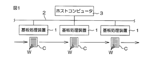
- FIG. 1 is a schematic diagram for explaining a substrate processing factory provided with a substrate processing apparatus 1 according to an embodiment of the present invention.
- the substrate processing factory is provided with a plurality of substrate processing apparatuses 1.
- the substrate processing apparatus 1 may be any of a cleaning apparatus, a heat treatment apparatus, a film forming apparatus, an etching apparatus, a resist coating apparatus, an exposure apparatus, and a developing apparatus, and may be an apparatus that performs other processing on the substrate.
- the substrate processing apparatus 1 may be a batch type apparatus that processes a plurality of substrates W at once, or may be a single wafer type apparatus that processes the substrates W one by one.
- One or a plurality of substrates W constituting one lot are accommodated in a common carrier C that can accommodate a maximum of 25 substrates W, for example.
- the carrier C is sequentially transferred to the plurality of substrate processing apparatuses 1.
- the substrate processing apparatus 1 is connected to a host computer 3 via a network 2.
- the host computer 3 sends a command to each substrate processing apparatus 1 based on the processing content of the substrate W set for each lot.
- the substrate processing apparatus 1 processes the substrate W based on a command from the host computer 3. Thereby, a series of processing is performed on the substrate W by the plurality of substrate processing apparatuses 1.
- FIG. 2 is a schematic diagram for explaining a schematic configuration example of the substrate processing apparatus 1.
- the substrate processing apparatus 1 includes an indexer block 4 into which the substrate W is loaded, a processing block 5 that processes the substrate W loaded into the indexer block 4, and a main controller that controls the operation of the equipment provided in the substrate processing apparatus 1. 6 (control device).
- the indexer block 4 includes a carrier holding unit 7, an indexer robot IR, and an IR moving mechanism 8.
- the carrier holding unit 7 can hold a plurality of carriers C.
- the plurality of carriers C are held by the carrier holding unit 7 in a state of being arranged along the horizontal carrier arrangement direction D1.
- the IR moving mechanism 8 moves the indexer robot IR in the carrier arrangement direction D1.
- the indexer robot IR performs a loading operation for loading the substrate W into the carrier C held by the carrier holding unit 7 and a loading operation for unloading the substrate W from the carrier C. Further, the indexer robot IR transports the substrate W in the indexer block 4 and also transports the substrate W between the indexer block 4 and the processing block 5.
- the indexer robot IR includes a plurality of hands H1 arranged at different heights.
- FIG. 2 shows a state in which a plurality of hands H1 are vertically overlapped.
- the processing block 5 includes a plurality of (for example, eight) processing units MPC for processing the substrates W one by one, a plurality of (for example, two) chemical liquid supply units CC that supply chemical liquids to the processing units MPC, A center robot CR that transports the substrate W in the processing block 5 and a shuttle SH that relays the substrate W between the indexer robot IR and the center robot CR are provided.
- the eight processing units MPC are arranged so as to surround the center robot CR in plan view in a state where two processing units MPC are stacked one above the other.
- the shuttle SH is disposed closer to the indexer block 4 than the center robot CR.
- the shuttle SH can hold a plurality of substrates W and transports the substrate W between the indexer robot IR and the center robot CR.
- the indexer robot IR and the center robot CR carry the substrate W into the shuttle SH and carry the substrate W out of the shuttle SH.
- the center robot CR transports the substrate W between the shuttle SH and the processing unit MPC.
- the center robot CR includes a plurality of hands H2 arranged at different heights.
- FIG. 2 shows a state in which a plurality of hands H2 are vertically overlapped.
- FIG. 3 is a schematic diagram for explaining a schematic configuration example of the processing unit MPC and the chemical solution supply unit CC.
- any number from 1 to 8 is added to the end of the processing unit MPC.
- any number from 1 to 2 is added to the end of the chemical solution supply unit CC.
- the processing unit MPC holds the substrate W horizontally and rotates it around a vertical axis passing through the center of the substrate W, and a chemical nozzle 10 that discharges the chemical toward the substrate W held by the spin chuck 9.
- a rinse liquid nozzle 11 that discharges a rinse liquid toward the substrate W held by the spin chuck 9, a chamber 12 that houses these configurations 9, 10, 11, and a first sensor that detects an abnormality in the processing unit MPC 13 (sensor).
- the chemical liquid nozzle 10 is connected to a chemical liquid pipe 14 extending from the chemical liquid supply unit CC.
- the chemical solution from the chemical solution supply unit CC is supplied to the chemical solution nozzle 10 via the chemical solution pipe 14.
- the rinse liquid nozzle 11 is connected to a rinse liquid pipe 15.
- the rinsing liquid nozzle 11 is supplied with pure water (deionized water) as an example of the rinsing liquid via the rinsing liquid pipe 15.
- the first sensor 13 may be, for example, a sensor that detects leakage in the chamber 12 or may be a sensor that detects leakage in the processing unit MPC.
- the chemical liquid supply unit CC includes a first tank 16 that stores the first liquid, a second tank 17 that stores the second liquid, a heater 18 that heats the chemical liquid, and a second sensor that detects an abnormality in the chemical liquid supply unit CC. 19 (sensor).
- the second sensor 19 may be, for example, a sensor that detects leakage in the chemical solution supply unit CC, or a sensor that detects leakage in the chemical solution supply unit CC.
- the chemical liquid supply unit CC is configured to generate a chemical liquid by mixing the first liquid and the second liquid.
- the chemical liquid nozzle 10 is supplied with a chemical liquid whose temperature is adjusted by the heater 18.
- four processing units MPC are connected to a common chemical solution supply unit CC. As shown in FIG.
- the chemical solution supplied to the chemical solution nozzle 10 may be any of a cleaning solution, an etching solution, a resist solution, and a developer, for example.
- Specific examples of the chemical solution include SC-1 (mixed solution containing NH 4 OH and H 2 O 2 ), BHF (mixed solution containing HF and NH 4 F), and SPM (H 2 SO 4 and H 2 O). 2 ).
- the main controller 6 rotates the substrate W by the spin chuck 9. Thereafter, the main controller 6 discharges the chemical solution from the chemical solution nozzle 10 toward the rotating substrate W. Thereby, the chemical solution is supplied to the substrate W (chemical solution treatment).
- the main controller 6 stops the supply of the chemical liquid to the substrate W, and then discharges pure water, which is an example of the rinse liquid, from the rinse liquid nozzle 11 toward the rotating substrate W. Thereby, pure water is supplied to the substrate W, and the chemical solution adhering to the substrate W is washed away (rinsing process). Then, after stopping the supply of pure water to the substrate W, the main controller 6 rotates the substrate W at a high rotation speed by the spin chuck 9.
- the pure water adhering to the substrate W is spun off around the substrate W by centrifugal force. Therefore, pure water is removed from the substrate W, and the substrate W is dried (drying process). In this way, the substrate W is processed by each processing unit MPC.
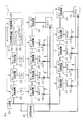
- FIG. 4 is a schematic diagram for explaining an electrical configuration of the substrate processing apparatus 1.
- the substrate processing apparatus 1 includes a main power supply 20 that distributes power supplied from a power supply source of a substrate processing factory to a plurality of devices, and a low-voltage power supply 21 that distributes power supplied from the main power supply 20 to a plurality of devices. And a plurality of on / off switching devices 22 that switch between an on state in which power from the main power supply 20 is supplied to the corresponding device and an off state in which power supply to the corresponding device is stopped.
- the main power supply 20 reduces the voltage of the power supplied from the power supply source of the substrate processing factory, and distributes the reduced power to the low voltage power supply 21 and the on / off switching device 22.
- the low-voltage power supply 21 reduces the voltage of the power supplied from the main power supply 20, and distributes the reduced power to the first sensor 13, the second sensor 19, and the like.
- the indexer robot IR, shuttle SH, and center robot CR are transfer units that perform a substrate transfer process.
- the on / off switching device 22 is provided for each transport unit. Further, the on / off switching device 22 is provided for each processing unit MPC that performs the substrate processing step. Similarly, the on / off switching device 22 is provided for each chemical supply unit CC that performs the chemical supply process. That is, the substrate transfer process, the substrate processing process, and the chemical solution supply process are processes for processing the substrate W, and the on / off switching device 22 includes units IR and SH that execute the process for processing the substrate W. , CR, MPC, and CC.
- unit U a unit that executes a process for processing the substrate W is simply referred to as “unit U”.
- the on / off switching device 22 is switched between an on state and an off state by being controlled by the main controller 6.
- Each unit U is supplied with power when the corresponding on / off switching device 22 is in the on state.
- power is constantly supplied to the main controller 6 and the sensors 13 and 19.
- the main controller 6 is connected to the host computer 3 (see FIG. 1) via the network 2.
- the main controller 6 communicates with the host computer 3.
- production information is transmitted from the host computer 3 to the main controller 6.
- the production information includes the processing content of the substrate W put into the substrate processing apparatus 1 and the end date of completion of all processes for processing the substrate W.
- the main controller 6 processes the substrate W put into the substrate processing apparatus 1 based on this production information.
- the main controller 6 includes a central processing unit 23, a storage device 24, and a scheduler 25 that functions when the central processing unit 23 executes a program stored in the storage device 24.
- the scheduler 25 includes a counter 26 that counts the number of times of substrate processing by each processing unit MPC.
- the scheduler 25 produces a time chart representing an operation plan of the plurality of units U so that all processes performed by the plurality of units U are completed before the end deadline according to the processing content of the substrate W included in the production information. Create based on information.
- the main controller 6 controls the plurality of on / off switching devices 22 based on the time chart, thereby supplying power to the plurality of units U and operating the plurality of units U. Thereby, the substrate W put into the substrate processing apparatus 1 is processed based on the production information.
- FIG. 5 is a graph illustrating an example of a time chart when processing the substrate W by operating eight processing units MPC.
- FIG. 6 is a graph showing an example of a time chart when processing the substrate W by operating four processing units MPC.
- the bar extending in the horizontal axis direction indicates that the corresponding unit is operating.
- the arrows shown in FIGS. 5 and 6 indicate the movement of the substrate W.
- an arrow extending from a bar labeled “1-1” to a bar labeled “1-2” represents the movement of the substrate W from the indexer robot IR to the shuttle SH.
- the numbers for example, “2-1” shown in the positions (positions in the vertical axis direction) corresponding to the indexer robot IR, the shuttle SH, the center robot CR, and the processing units MPC1 to MPC8.
- the numerals shown at the positions corresponding to the chemical solution supply units CC1 and CC2 indicate to which processing unit MPC the chemical solution supply unit CC supplies the chemical solution.
- “1” shown at a position corresponding to the chemical solution supply unit CC1 indicates that the chemical solution is supplied from the chemical solution supply unit CC1 to the processing unit MPC1.
- ⁇ -1 step where “ ⁇ ” may be any number
- the substrate W unloaded from the carrier C is transferred to the shuttle SH. Including the process until loading.
- the second process (the process of “ ⁇ -2”) is a process from when the shuttle SH starts moving to the indexer robot IR until the substrate W loaded by the indexer robot IR is unloaded by the center robot CR. Including.
- the third process (the process of “ ⁇ -3”) is a process from when the central robot CR starts preparation for unloading the substrate W from the shuttle SH until the substrate W unloaded from the shuttle SH is loaded into the processing unit MPC. including.
- the fourth step (“ ⁇ -4” step) is a step from when the center robot CR carries the substrate W into the processing unit MPC until the substrate W processed by the processing unit MPC is carried out by the center robot CR. including. First, an example of a time chart when the eight processing units MPC1 to MPC8 are operated to process 25 substrates W will be described.
- the main controller 6 transports the first substrate W from the carrier C to the processing unit MPC1 by the indexer robot IR, the shuttle SH, and the center robot CR (1-1, 1-2, 1). -3).
- the main controller 6 starts the transport of the second substrate W by the indexer robot IR (2-1).
- the main controller 6 causes the second substrate W to be transferred from the shuttle SH to the processing unit MPC2 by the shuttle SH and the center robot CR (2-2, 2-3).
- the main controller 6 causes the indexer robot IR, the shuttle SH, and the center robot CR to repeatedly execute such an operation, thereby loading the first to eighth substrates W into the processing units MPC1 to MPC8, respectively.
- the main controller 6 puts the indexer robot IR, shuttle SH, and center robot CR on standby.
- the main controller 6 operates the chemical liquid supply unit CC2 to supply the chemical liquid from the chemical liquid supply unit CC2 to the processing units MPC5 to 8.
- the main controller 6 puts the chemical liquid supply unit CC2 on standby.
- the main controller 6 sequentially transfers the eight substrates W processed in the processing units MPC1 to 8 from the processing units MPC1 to 8 to the carrier C. Specifically, the main controller 6 transports the ninth substrate W from the carrier C to the center robot CR in accordance with the timing when the processing of the first substrate W in the processing unit MPC1 is completed (9 ⁇ 1, 9-2). Then, the main controller 6 unloads the first substrate W from the processing unit MPC1 with the hand H2 not holding the substrate W of the center robot CR (1-5).
- the main controller 6 causes the hand H2 holding the ninth substrate W of the center robot CR to enter the processing unit MPC1, and loads the ninth substrate W into the processing unit MPC1 (9 ⁇ ). 3).
- the ninth substrate W is processed by the processing unit MPC1 (9-4).
- the process of the center robot CR unloading the substrate W from the processing unit MPC (fifth process. Step -5 ”) is included.
- the main controller 6 transports the tenth substrate W from the carrier C to the shuttle SH in accordance with the timing when the processing of the second substrate W in the processing unit MPC2 is completed (10-1).
- the center robot CR holds the first substrate W.
- the main controller 6 loads the first substrate W into the shuttle SH by the center robot CR (1-6).
- the main controller 6 causes the center robot CR to carry out the tenth substrate W from the shuttle SH (10-2).
- the main controller 6 causes the center robot CR to carry the tenth substrate W into the processing unit MPC2 (10-3).
- the center robot CR carries the substrate W into the shuttle SH (sixth step. Step 6)) is included.
- the main controller 6 causes the indexer robot IR to carry out the eleventh substrate W from the carrier C in accordance with the timing when the processing of the third substrate W in the processing unit MPC3 is completed.
- the shuttle SH holds the first substrate W.
- the main controller 6 unloads the first substrate W from the shuttle SH by the hand H1 not holding the substrate W of the indexer robot IR (1-7).
- the main controller 6 loads the eleventh substrate W into the shuttle SH with the hand H1 holding the substrate W of the indexer robot IR (11-1).
- the main controller 6 loads the eleventh substrate W from the shuttle SH into the processing unit MPC3 by the shuttle SH and the center robot CR (11-2, 11-3).
- the main controller 6 causes the first substrate W held by the indexer robot IR to be carried into the carrier C by the indexer robot IR.
- the indexer robot IR carries out the substrate W from the shuttle SH (seventh process. 7 ”).
- the main controller 6 causes each unit U to repeatedly execute such an operation. That is, for the ninth and subsequent substrates W, the main controller 6 transfers the substrate W to the carrier C in parallel with the transfer of the substrate W to the processing units MPC1 to MPC8, the indexer robot IR, the shuttle SH, and The central robot CR is executed. For the last eight substrates W (18th to 25th substrates W) processed by the processing units MPC1 to MPC8, the main controller 6 performs only the transport of the substrate W to the carrier C as an indexer. The robot IR, the shuttle SH, and the center robot CR are executed. In this way, in the time chart shown in FIG. 5, 25 substrates W are processed by repeating one cycle from the processing of the substrate W in the processing unit MPC1 to the processing of the substrate W in the processing unit MPC8.
- the main controller 6 causes the indexer robot IR, shuttle SH, and center robot CR to transfer the first substrate W from the carrier C to the processing unit MPC1 (1-1, 1-2, 1). -3).
- the main controller 6 starts the transport of the second substrate W by the indexer robot IR (2-1).
- the main controller 6 causes the second substrate W to be transferred from the shuttle SH to the processing unit MPC2 by the shuttle SH and the center robot CR (2-2, 2-3).
- the main controller 6 causes the indexer robot IR, the shuttle SH, and the center robot CR to repeatedly execute such an operation, thereby loading the first to fourth substrates W into the processing units MPC1 to MPC4, respectively.
- the main controller 6 puts the indexer robot IR, shuttle SH, and center robot CR on standby.
- the main controller 6 operates the chemical liquid supply unit CC1 to supply the chemical liquid from the chemical liquid supply unit CC1 to the processing units MPC1 to MPC4.
- the main controller 6 puts the chemical liquid supply unit CC1 on standby.
- the main controller 6 waits for the chemical solution supply unit CC2. That is, the chemical solution supply unit CC2 is in a non-operating state.
- the main controller 6 sequentially transports the four substrates W processed in the processing units MPC1 to MPC4 to the carrier C from the processing units MPC1 to MPC4. Specifically, the main controller 6 transports the fifth substrate W from the carrier C to the central robot CR in accordance with the timing when the processing of the first substrate W in the processing unit MPC1 is completed (5- 1, 5-2). Then, the main controller 6 unloads the first substrate W from the processing unit MPC1 with the hand H2 not holding the substrate W of the center robot CR (1-5).
- the main controller 6 causes the hand H2 holding the fifth substrate W of the center robot CR to enter the processing unit MPC1, and loads the fifth substrate W into the processing unit MPC1 (5- 3). Accordingly, the fifth substrate W is processed by the processing unit MPC1 subsequent to the first substrate W (5-4). As described above, in the third step performed on the fifth and subsequent substrates W in the time chart shown in FIG. 6, the center robot CR carries out the substrate W from the processing unit MPC (fifth step. Step -5 ”) is included.
- the main controller 6 transfers the sixth substrate W from the carrier C to the shuttle SH in accordance with the timing when the processing of the second substrate W in the processing unit MPC2 is completed (6-1).
- the center robot CR holds the first substrate W.
- the main controller 6 loads the first substrate W into the shuttle SH by the center robot CR (1-6).
- the main controller 6 causes the center robot CR to carry out the sixth substrate W from the shuttle SH (6-2).
- the main controller 6 loads the sixth substrate W into the processing unit MPC2 by the center robot CR (6-3).
- the step of the center robot CR carrying the substrate W into the shuttle SH (sixth step. Step 6)) is included.
- the main controller 6 causes the indexer robot IR to carry out the seventh substrate W from the carrier C in accordance with the timing when the processing of the third substrate W in the processing unit MPC3 is completed.
- the shuttle SH holds the first substrate W.
- the main controller 6 unloads the first substrate W from the shuttle SH by the hand H1 not holding the substrate W of the indexer robot IR (1-7).
- the main controller 6 loads the seventh substrate W into the shuttle SH with the hand H1 holding the substrate W of the indexer robot IR (7-1).
- the main controller 6 loads the seventh substrate W from the shuttle SH to the processing unit MPC3 by the shuttle SH and the center robot CR (7-2, 7-3).
- the main controller 6 causes the first substrate W held by the indexer robot IR to be carried into the carrier C by the indexer robot IR.
- the indexer robot IR carries out the substrate W from the shuttle SH (seventh process. 7 ”).
- the main controller 6 causes each unit U to repeatedly execute such an operation. That is, for the fifth and subsequent substrates W, the main controller 6 transfers the substrate W to the carrier C in parallel with the transfer of the substrate W to the processing units MPC1 to MPC4.
- the central robot CR is executed.
- the main controller 6 performs only the transport of the substrate W to the carrier C as an indexer.
- the robot IR, the shuttle SH, and the center robot CR are executed. As described above, in the second time chart, 25 substrates W are processed by repeating one cycle from the processing of the substrate W in the processing unit MPC1 to the processing of the substrate W in the processing unit MPC4.
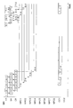
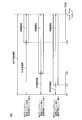
- FIG. 7 is a graph for explaining the first to fourth time charts.
- the first to third time charts are examples of the present invention, and the fourth time chart is a comparative example.
- Each of the first to fourth time charts is a time chart when 25 substrates W are processed.
- the difference between the first to fourth time charts is the number of processing units MPC operated and the number of chemical solution supply units CC operated.
- the substrate W is processed by eight processing units MPC, and in the second time chart, the substrate W is processed by four processing units MPC.
- the substrate W is processed by the three processing units MPC, and in the fourth time chart, the substrate W is processed by the two processing units MPC.
- two chemical liquid supply units CC are operated, and in the second to fourth time charts, one chemical liquid supply unit CC is operated.
- each unit U in the first time chart is as described with reference to FIG. 5, and the operation of each unit U in the second time chart is as described with reference to FIG.
- the operation of each unit U in the third and fourth time charts is the same as the operation of each unit U in the second time chart. That is, in the third time chart, one cycle from the processing of the substrate W in the processing unit MPC1 to the processing of the substrate W in the processing unit MPC3 is repeated. In the fourth time chart, one cycle from the processing of the substrate W by the processing unit MPC1 to the processing of the substrate W by the processing unit MPC2 is repeated.
- the operations of the plurality of units U are started from the loading time Tin of the substrate W to the substrate processing apparatus 1. That is, in the first to fourth time charts, the start times Ts1 to Ts4 at which the operation of at least one unit U is started coincide with the input time Tin. End times Te1 to Te4 at which all processes performed by the plurality of units U are completed are earlier in the order of the first time chart, the second time chart, the third time chart, and the fourth time chart. Further, the end times Te1 to 3 of the first to third time charts are earlier than the end time limit LT, and the end time Te4 of the fourth time chart is later than the end time limit LT. Accordingly, in the first to third time charts, all processes performed by the plurality of units U are completed before the end time limit LT.
- the operation period in which at least one of the plurality of units U is operated is shorter than the executable period that is the period from the input time Tin to the end deadline LT.
- the main controller 6 controls the plurality of on / off switching devices 22 to stop the power supply to at least one of the plurality of units U during all or part of the non-operation period.
- the main controller 6 controls the plurality of on / off switching devices 22 to stop the power supply to the unit U that is not in operation during the operation period. That is, as shown in FIG. 5, the main controller 6 completes the first step (8-1) for the ninth substrate W after completing the first step (8-1) for the eighth substrate W.
- the indexer robot IR is kept on standby until it is started.
- the shuttle SH, the central robot CR, the processing units MPC1 to 8 and the chemical solution supply units CC1 to CC2 also have a waiting period during the period (operation period) in which the first time chart is being executed.
- the standby unit U is in a non-operating state.
- the main controller 6 controls the on / off switching device 22 corresponding to the unit U in the non-operating state even during the period of executing the first time chart. By doing so, the power supply to at least one non-operating unit U is stopped.
- the processing units MPC5 to 8 and the chemical solution supply unit CC2 are not operated. That is, the processing units MPC5 to 8 and the chemical solution supply unit CC2 are in a non-operating state during the period (operating period) in which the second time chart is being executed. Therefore, the main controller 6 stops the power supply to the processing units MPC5 to 8 and the chemical solution supply unit CC2 during all or part of the period even during the period when the second time chart is being executed. . Thereby, for example, since the power consumption by the heater 18 of the chemical solution supply unit CC2 is reduced, the power consumption of the entire substrate processing apparatus 1 is reduced.
- the main controller 6 stops the power supply to the processing units MPC4 to MPC4 and the chemical solution supply unit CC2 during all or part of this period even during the period when the third time chart is being executed. . Thereby, the power consumption of the whole substrate processing apparatus 1 is reduced.
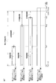
- FIG. 8 is a graph for explaining the fifth to seventh time charts.
- the fifth to seventh time charts are the same time charts as the first to third time charts, respectively. That is, as can be seen from a comparison between FIG. 7 and FIG. 8, the first time chart and the fifth time chart differ only in the start times Ts1 and Ts5, and the operation of the unit U and the operation of each unit U are the same. .
- the second time chart and the sixth time chart only the start times Ts2 and Ts6 are different, and the operation of the operating unit U and each unit U is the same.
- the third time chart and the seventh time chart differ only in the start times Ts3 and Ts7, and the operation of the operating unit U and each unit U is the same.
- the fifth to seventh time charts similarly to the first to third time charts, power supply to at least one unit U is stopped during all or part of the non-operation period. Further, in the fifth to seventh time charts, similarly to the first to third time charts, the power supply to the non-operating unit U that is not operated during the operation period is stopped. As shown in FIG. 8, in the fifth to seventh time charts, the operations of the plurality of units U are started so that the end times Te5 to Te7 and the end time limit LT coincide. That is, in the fifth to seventh time charts, the start times Ts5 to 7 are later than the loading time Tin of the substrate W to the substrate processing apparatus 1. As described above, the chemical liquid supply unit CC generates, for example, a chemical liquid by mixing the first liquid and the second liquid.
- the chemical liquid produced by mixing the first liquid and the second liquid may have a certain life (lifetime) starting after mixing.
- life life starting after mixing.
- the chemical solution supply unit CC newly generates a chemical solution
- the first solution and the second solution are added before the substrate W is loaded into the substrate processing apparatus 1 or at an early stage of the executable period. Need to start mixing.
- the chemical solution is not used between the end times Te1 to Te3 and the end time limit LT, and the life of the chemical solution is wasted.
- the end times Te5 to 7 and the end time limit LT coincide with each other, so that the life of the chemical solution is between the end time Te5 to 7 and the end time limit LT. Is not wasted.
- the time for starting the mixing of the first liquid and the second liquid can be delayed as compared with the first to third time charts, and therefore, from the charging time Tin to the starting time Ts5 to 7, It is possible to prevent the life of the chemical solution from being wasted. Thereby, a chemical
- FIG. 9 is a graph for explaining a processing example when the substrate processing apparatus 1 processes a plurality of lots.
- a plurality of carriers C are sequentially transferred to the substrate processing apparatus 1
- a plurality of pieces of production information corresponding to the plurality of carriers C are sequentially transmitted from the host computer 3 to the main controller 6.
- the main controller 6 acquires a plurality of pieces of production information and creates a plurality of time charts respectively corresponding to the plurality of pieces of production information.
- the main controller 6 operates a plurality of units U based on a plurality of time charts. Thereby, a plurality of lots are sequentially processed.
- the carrier C in which one substrate W is accommodated, the carrier C in which two substrates W are accommodated, and the carrier C in which 25 substrates W are accommodated are sequentially supplied to the substrate processing apparatus 1.
- one substrate W of the first lot is processed as shown in Example 1 in FIG. Thereafter, the two substrates W of the next lot are continuously processed. Then, the 25 substrates W of the last lot are processed continuously.
- the main controller 6 acquires the plurality of pieces of production information and integrates these pieces of production information into one. Then, the main controller 6 creates a time chart based on the integrated production information. Specifically, the carrier C in which one substrate W is accommodated, the carrier C in which two substrates W are accommodated, and the carrier C in which 25 substrates W are accommodated are sequentially supplied to the substrate processing apparatus 1. When transported, as shown in the second embodiment of FIG. 9, the main controller 6 creates a time chart (eighth time chart) in which 28 substrates W are processed continuously. Then, the main controller 6 operates a plurality of units U based on this time chart. Thereby, 28 substrates W are processed continuously.
- FIG. 10 is a graph for explaining a processing example when the substrate processing apparatus 1 processes a plurality of lots.
- the main controller 6 includes the counter 26 that counts the number of times of substrate processing by each processing unit MPC.
- the main controller 6 creates a time chart in which the substrate processing times of each processing unit MPC are averaged. That is, for example, when the carrier C containing four substrates W is sequentially transferred to the substrate processing apparatus 1, the main controller 6 processes the four substrates W by the processing units MPC1 to MPC4 in the first lot.
- a time chart (9th time chart) is created, and a plurality of units U are operated based on this time chart.
- the main controller 6 creates a time chart (tenth time chart) for processing the four substrates W by the processing units MPC5 to 8 and operates a plurality of units U based on this time chart.
- the main controller 6 creates a time chart (9th time chart) for processing the four substrates W by the processing units MPC1 to MPC4, and operates a plurality of units U based on this time chart. .
- the main controller 6 operates the plurality of units U so that the processing of the substrate W in the processing units MPC1 to MPC4 and the processing of the substrate W in the processing units MPC5 to MPC8 are alternately performed. Thereby, the number of substrate processings of each processing unit MPC is averaged.
- the main controller 6 acquires production information including the processing content of the substrate W put into the substrate processing apparatus 1 and the end time limit LT. Based on the production information, the main controller 6 generates a time chart representing an operation plan of the plurality of units U so that all processes performed by the plurality of units U are completed before the end deadline LT according to the processing content. create.
- the main controller 6 operates the plurality of units U based on the time chart and controls the plurality of on / off switching devices 22 based on the time chart.
- the main controller 6 can identify, for example, the unit U that is in standby (non-operating state) or the unit U that is in a standby state for a long time based on the time chart.
- the power supply to U can be stopped systematically. Thereby, power consumption is reduced. Further, by using the production information, a time chart can be created so that a plurality of units U can be operated optimally, so that power consumption can also be reduced by optimizing the time chart. Thus, the power consumption of the substrate processing apparatus 1 can be effectively reduced by creating the time chart using the production information and controlling the power supply to each unit U performed based on the time chart. .
- the main controller 6 determines that all of the plurality of units U are based on the time chart among the executable periods that are the period from the loading time Tin of the substrate W to the substrate processing apparatus 1 to the end time limit LT. In the non-operating period during which operation is not performed, power supply to at least one of the plurality of units U is stopped. That is, during the non-operating period, power supply to the unit U is not necessary, so the main controller 6 stops power supply to at least one of the plurality of units U during all or part of this period. Thereby, power consumption is reduced.
- the main controller 6 stops power supply to at least one non-operating unit U during an operation period in which at least one of the plurality of units U is operated based on the time chart. That is, since the power supply to the non-operating unit U is not necessary even during the operation period, the main controller 6 stops the power supply to the non-operating unit U. Thereby, power consumption is reduced.
- the main controller 6 creates a time chart (third and seventh time charts) in which the number of processing units MPC to be operated is the smallest, and operates a plurality of units U based on this time chart.
- the main controller 6 creates a time chart in which the number of non-operating processing units MPC is the largest, and operates a plurality of units U based on this time chart. Therefore, the main controller 6 controls the plurality of on / off switching devices 22 to supply power to the processing unit MPC in the non-operating state and the unit U in which the non-operating state continues for a long time even during the operation period. Can be stopped.
- the power consumption can be further reduced.
- the main controller 6 creates a time chart (second, third, sixth, and seventh time chart) in which the number of operated chemical supply units CC is minimized, Based on this, a plurality of units U are operated.
- the main controller 6 creates a time chart in which the number of non-operating chemical solution supply units CC is the largest, and operates a plurality of units U based on this time chart. Therefore, the main controller 6 can stop the power supply to the non-operating chemical solution supply unit CC even during the operation period by controlling the plurality of on / off switching devices 22.
- the power consumption can be further reduced.
- the number of chemical solution supply units CC to be operated is small, the amount of chemical solution prepared (preparation, temperature adjustment, etc.) in the substrate processing apparatus 1 is accordingly reduced. Thereby, chemical consumption can be reduced.
- the main controller 6 creates a time chart (fifth to seventh time charts) in which the operation start time of the chemical solution supply unit CC is later than the loading time Tin of the substrate W into the substrate processing apparatus 1.
- a plurality of units U are operated based on this time chart. Accordingly, it is possible to shorten the period from the end times Te5 to Te7 at which all the steps performed by the plurality of units U are completed to the end time limit LT.
- the end times Te5 to Te7 and the end time limit LT coincide with each other, the period from the end time Te5 to 7 to the end time limit LT can be eliminated.
- the chemical solution Since the chemical solution is not supplied to the substrate W during the period from the completion of all the steps performed by the plurality of units U to the end time limit LT, the period in which the life of the chemical solution is wasted by shortening this period Can be shortened. Thereby, a chemical
- the main controller 6 acquires a plurality of pieces of production information and creates a time chart (eighth time chart) in which a plurality of substrates W corresponding to the plurality of pieces of production information are continuously processed. That is, the main controller 6 integrates a plurality of production information and creates a time chart based on the integrated production information. Then, the main controller 6 operates a plurality of units U based on this time chart. Since a plurality of substrates W corresponding to a plurality of production information are continuously processed, the operation period can be shortened as compared with a case where a plurality of substrates W are processed intermittently. In other words, the non-operation period can be increased. Therefore, power consumption can be further reduced.
- the number of times of substrate processing by each processing unit MPC is counted by the counter 26 of the main controller 6.
- the main controller 6 creates time charts (9th and 10th time charts) in which the number of substrate processings of each processing unit MPC is averaged. Therefore, when maintenance parts to be replaced according to the number of times of substrate processing are provided in each processing unit MPC, the number of times of use of each maintenance part can be averaged. Therefore, the plurality of maintenance parts can be replaced at the same time because the replacement times of the plurality of maintenance parts match or substantially match. Accordingly, the number of times that the substrate processing apparatus 1 is stopped in order to replace maintenance parts can be reduced, so that the productivity of the substrate processing apparatus 1 can be improved. In addition, when some maintenance parts need to be replaced, even if other maintenance parts are also replaced, each maintenance part is used on average, so each maintenance part can be used efficiently. can do.
- the sensors 13 and 19 for detecting an abnormality of the substrate processing apparatus 1 are provided in the substrate processing apparatus 1. Electric power is constantly supplied to the sensors 13 and 19. Therefore, the abnormality of the substrate processing apparatus 1 can be reliably detected. That is, the power consumption of the substrate processing apparatus 1 can be reduced without sacrificing the abnormality detection operation.
- the case where the end times Te5 to Te7 of the fifth to seventh time charts coincide with the end time limit LT has been described (see FIG. 8).
- the end times Te5 to Te7 of the fifth to seventh time charts may be earlier than the end time limit LT.
- the case where the four processing units MPC are connected to the common chemical supply unit CC has been described.
- a chemical solution supply unit CC may be provided for each processing unit MPC.
- Substrate processing device 6 Main controller (control device) 13 First sensor (sensor) 19 Second sensor (sensor) 22 ON / OFF switching device 26 Counter CC Chemical supply unit (unit) CR Center robot (unit) IR indexer robot (unit) MPC processing unit (unit) SH shuttle (unit) W substrate
Landscapes
- Engineering & Computer Science (AREA)
- Physics & Mathematics (AREA)
- General Physics & Mathematics (AREA)
- Automation & Control Theory (AREA)
- General Engineering & Computer Science (AREA)
- Manufacturing & Machinery (AREA)
- Quality & Reliability (AREA)
- Cleaning Or Drying Semiconductors (AREA)
Abstract
Description
そこで、この発明の目的は、電力消費量を低減することができる基板処理装置および電源管理方法を提供することである。
この構成によれば、制御装置は、複数のユニットの少なくとも1つがタイムチャートに基づいて稼働される稼働期間において、少なくとも1つの非稼働状態のユニットに対する電力供給を停止させる。すなわち、稼働期間中であっても非稼働状態のユニットへの電力供給は必要でないので、制御装置は、非稼働状態のユニットへの電力供給を停止させる。これにより、電力消費量が低減される。
この構成によれば、制御装置は、稼働される処理ユニットの数が最も少なくなるようにタイムチャートを作成し、このタイムチャートに基づいて複数のユニットを稼働させる。言い換えると、制御装置は、非稼働状態の処理ユニットの数が最も多くなるようにタイムチャートを作成し、このタイムチャートに基づいて複数のユニットを稼働させる。したがって、制御装置は、複数のオン・オフ切替装置を制御することにより、稼働期間中であっても非稼働状態の処理ユニットや非稼働状態が長時間継続するユニットへの電力供給を停止させることができる。このタイムチャートでは、非稼働状態の処理ユニットの数が最も多いので、電力消費量を一層低減することができる。
この構成によれば、制御装置は、稼働される薬液供給ユニットの数が最も少なくなるようにタイムチャートを作成し、このタイムチャートに基づいて複数のユニットを稼働させる。言い換えると、制御装置は、非稼働状態の薬液供給ユニットの数が最も多くなるようにタイムチャートを作成し、このタイムチャートに基づいて複数のユニットを稼働させる。したがって、制御装置は、複数のオン・オフ切替装置を制御することにより、稼働期間中であっても非稼働状態の薬液供給ユニットへの電力供給を停止させることができる。このタイムチャートでは、非稼働状態の薬液供給ユニットの数が最も多いので、電力消費量を一層低減することができる。さらに、稼働される薬液供給ユニットの数が少ないので、それに応じて、基板処理装置内で準備(調合や温度調整など)される薬液量が少なくなる。これにより、薬液消費量を削減できる。
この構成によれば、制御装置は、薬液供給ユニットの稼働開始時間が基板処理装置への基板の投入時間より遅くなるようにタイムチャートを作成し、このタイムチャートに基づいて複数のユニットを稼働させる。したがって、複数のユニットによって行われる全ての工程が終了する終了時間から終了期限までの期間を短縮することができる。終了時間から終了期限までの期間は、薬液が基板に供給されないから、この期間を短縮することにより、薬液の寿命が無駄に消費される期間を短縮することができる。換言すれば、薬液の使用開始を遅らせることによって、薬液の寿命が尽きる時間がより遅くなるので、実質的に薬液の寿命が長くなったのと同等の効果が得られる。これにより、薬液をより多くの基板処理に使えるようになるから、薬液の消費量を削減できる。
この構成によれば、制御装置は、複数の生産情報を取得し、複数の生産情報に対応する複数枚の基板が連続的に処理されるようにタイムチャートを作成する。すなわち、制御装置は、複数の生産情報を統合し、この統合された生産情報に基づいてタイムチャートを作成する。そして、制御装置は、このタイムチャートに基づいて複数のユニットを稼働させる。これにより、複数の生産情報に対応する複数枚の基板が連続的に処理される。したがって、複数枚の基板が断続的に処理される場合に比べて、稼働期間を短縮することができる。言い換えると、非稼働期間を増加させることができる。したがって、電力消費量を一層低減することができる。
この構成によれば、各処理ユニットによる基板処理回数が、制御装置のカウンターによって数えられる。制御装置は、各処理ユニットの基板処理回数が平均化するようにタイムチャートを作成する。したがって、基板処理回数に応じて交換されるメンテナンス部品が各処理ユニットに設けられている場合には、各メンテナンス部品の使用回数を平均化することができる。そのため、複数のメンテナンス部品の交換の時期が、一致またはほぼ一致するので、複数のメンテナンス部品を同時に交換することができる。したがって、メンテナンス部品を交換するために基板処理装置を停止させる回数を減少させることができるから、基板処理装置の生産性を向上できる。さらに、一部のメンテナンス部品の交換が必要になったときに、他のメンテナンス部品も併せて交換したとしても、各メンテナンス部品が平均的に使用されているので、各メンテナンス部品を効率的に使用することができる。
この構成によれば、基板処理装置の異常を検出するセンサが基板処理装置に設けられている。このセンサには、電力が常時供給される。したがって、基板処理装置の異常を確実に検出することができる。つまり、異常検出動作を犠牲にすることなく、基板処理装置の消費電力量を低減できる。
基板処理工場には、複数の基板処理装置1が備えられている。基板処理装置1は、洗浄装置、熱処理装置、成膜装置、エッチング装置、レジスト塗布装置、露光装置、および現像装置のいずれであってもよく、基板に対するその他の処理を行う装置であってもよい。また、基板処理装置1は、複数枚の基板Wを一括して処理するバッチ式の装置であってもよいし、基板Wを1枚ずつ処理する枚葉式の装置であってもよい。1つのロットを構成する1枚または複数枚の基板Wは、たとえば最大で25枚の基板Wを収容可能な共通のキャリアCに収容されている。キャリアCは、複数の基板処理装置1に順次搬送される。基板処理装置1は、ネットワーク2を介してホストコンピュータ3に接続されている。ホストコンピュータ3は、ロットごとに設定された基板Wの処理内容に基づいて各基板処理装置1に指令を送る。基板処理装置1は、ホストコンピュータ3からの指令に基づいて基板Wを処理する。これにより、一連の処理が複数の基板処理装置1によって基板Wに行われる。
基板処理装置1は、基板Wが搬入されるインデクサブロック4と、インデクサブロック4に搬入された基板Wを処理する処理ブロック5と、基板処理装置1に備えられた機器の動作を制御するメインコントローラ6(制御装置)とを備えている。
基板処理装置1は、基板処理工場の電力供給源から供給された電力を複数の機器に分配する主電源20と、主電源20から供給された電力を複数の機器に分配する低電圧電源21と、主電源20からの電力を対応する機器に供給するオン状態と、対応する機器への電力供給を停止するオフ状態との間で切り替わる複数のオン・オフ切替装置22とをさらに含む。主電源20は、基板処理工場の電力供給源から供給された電力の電圧を低下させ、この電圧が低下した電力を低電圧電源21やオン・オフ切替装置22等に分配する。同様に、低電圧電源21は、主電源20から供給された電力の電圧を低下させ、この電圧が低下した電力を第1センサ13や第2センサ19等に分配する。
図5および図6において横軸方向に延びるバーは、対応するユニットが稼働していることを表している。さらに、図5および図6に示された矢印は、基板Wの移動を表している。たとえば、「1-1」と記されたバーから「1-2」と記されたバーに延びる矢印は、インデクサロボットIRからシャトルSHへの基板Wの移動を表している。
第1工程(「○-1」の工程。「○」はどの数字でも良い。)は、インデクサロボットIRがキャリアCへの移動を開始してから、キャリアCから搬出した基板WをシャトルSHに搬入するまでの工程を含む。
第3工程(「○-3」の工程)は、センターロボットCRがシャトルSHから基板Wを搬出する準備を開始してから、シャトルSHから搬出した基板Wを処理ユニットMPCに搬入するまでの工程を含む。
最初に、8つの処理ユニットMPC1~8を稼働させて25枚の基板Wを処理するときのタイムチャートの一例について説明する。
図6に示すように、メインコントローラ6は、インデクサロボットIR、シャトルSH、およびセンターロボットCRによって1枚目の基板WをキャリアCから処理ユニットMPC1に搬送させる(1-1、1-2、1-3)。インデクサロボットIRによる1枚目の基板Wの搬送が終了すると、メインコントローラ6は、インデクサロボットIRによる2枚目の基板Wの搬送を開始させる(2-1)。そして、メインコントローラ6は、シャトルSHおよびセンターロボットCRによって2枚目の基板WをシャトルSHから処理ユニットMPC2に搬送させる(2-2、2-3)。メインコントローラ6は、このような動作をインデクサロボットIR、シャトルSH、およびセンターロボットCRに繰り返し実行させることにより、1枚目から4枚目までの基板Wをそれぞれ処理ユニットMPC1~4に搬入させる。そして、処理ユニットMPC1~4に4枚の基板Wが搬入された後は、メインコントローラ6は、インデクサロボットIR、シャトルSH、およびセンターロボットCRを待機させる。
第1~第4タイムチャートは、いずれも25枚の基板Wを処理するときのタイムチャートである。第1~第4タイムチャートの相違点は、稼働される処理ユニットMPCの数と、稼働される薬液供給ユニットCCの数である。
第5~第7タイムチャートは、それぞれ、第1~第3タイムチャートと同様のタイムチャートである。すなわち、図7と図8とを比較すると分かるように、第1タイムチャートと第5タイムチャートは、開始時間Ts1、Ts5が異なるだけで、稼働するユニットUおよび各ユニットUの動作は同じである。同様に、第2タイムチャートと第6タイムチャートは、開始時間Ts2、Ts6が異なるだけで、稼働するユニットUおよび各ユニットUの動作は同じである。同様に、第3タイムチャートと第7タイムチャートは、開始時間Ts3、Ts7が異なるだけで、稼働するユニットUおよび各ユニットUの動作は同じである。
図8に示すように、第5~第7タイムチャートでは、終了時間Te5~7と終了期限LTとが一致するように複数のユニットUの動作が開始される。すなわち、第5~第7タイムチャートでは、開始時間Ts5~7が基板処理装置1への基板Wの投入時間Tinよりも遅い。前述のように、薬液供給ユニットCCは、たとえば、第1液と第2液とを混合させて薬液を生成する。第1液と第2液との混合により生成された薬液は、混合されてから始まる一定の寿命(ライフタイム)を有している場合がある。薬液供給ユニットCCが新たに薬液を生成する場合、第1~3タイムチャートでは、基板処理装置1への基板Wの投入までに、または実行可能期間の早い段階で第1液と第2液との混合を開始する必要がある。さらに、図7に示すように、第1~3タイムチャートでは、終了時間Te1~3から終了期限LTまでの間は薬液が使用されず、薬液の寿命が無駄に消費される。
複数のキャリアCが基板処理装置1に順次搬送されるとき、複数のキャリアCにそれぞれ対応する複数の生産情報がホストコンピュータ3からメインコントローラ6に順次送信される。メインコントローラ6は、複数の生産情報を取得し、複数の生産情報にそれぞれ対応する複数のタイムチャートを作成する。そして、メインコントローラ6は、複数のタイムチャートに基づいて複数のユニットUを稼働させる。これにより、複数のロットが順次処理される。具体的には、1枚の基板Wが収容されたキャリアCと、2枚の基板Wが収容されたキャリアCと、25枚の基板Wが収容されたキャリアCとが順次基板処理装置1に搬送された場合には、図9の実施例1に示すように、最初のロットの1枚の基板Wが処理される。その後、次のロットの2枚の基板Wが連続的に処理される。そして、最後のロットの25枚の基板Wが連続的に処理される。
前述のように、メインコントローラ6は、各処理ユニットMPCによる基板処理回数を数えるカウンター26を含む。メインコントローラ6は、各処理ユニットMPCの基板処理回数が平均化するタイムチャートを作成する。すなわち、たとえば4枚の基板Wが収容されたキャリアCが基板処理装置1に順次搬送される場合、メインコントローラ6は、最初のロットでは、処理ユニットMPC1~4によって4枚の基板Wを処理するタイムチャート(第9タイムチャート)を作成し、このタイムチャートに基づいて複数のユニットUを稼働させる。そして、メインコントローラ6は、次のロットでは、処理ユニットMPC5~8によって4枚の基板Wを処理するタイムチャート(第10タイムチャート)を作成し、このタイムチャートに基づいて複数のユニットUを稼働させる。さらに次のロットでは、メインコントローラ6は、処理ユニットMPC1~4によって4枚の基板Wを処理するタイムチャート(第9タイムチャート)を作成し、このタイムチャートに基づいて複数のユニットUを稼働させる。このように、メインコントローラ6は、処理ユニットMPC1~4での基板Wの処理と、処理ユニットMPC5~8での基板Wの処理とが交互に行われるように複数のユニットUを稼働させる。これにより、各処理ユニットMPCの基板処理回数が平均化される。
この発明の実施の形態の説明は以上であるが、この発明は、前述の実施形態の内容に限定されるものではなく、請求項記載の範囲内において種々の変更が可能である。
また、前述の実施形態では、4つの処理ユニットMPCが共通の薬液供給ユニットCCに接続されている場合について説明した。しかし、処理ユニットMPCごとに薬液供給ユニットCCが設けられていてもよい。
この出願は、2011年3月16日に日本国特許庁に提出された特願2011-058263号に対応しており、この出願の全開示はここに引用により組み込まれるものとする。
6 メインコントローラ(制御装置)
13 第1センサ(センサ)
19 第2センサ(センサ)
22 オン・オフ切替装置
26 カウンター
CC 薬液供給ユニット(ユニット)
CR センターロボット(ユニット)
IR インデクサロボット(ユニット)
MPC 処理ユニット(ユニット)
SH シャトル(ユニット)
W 基板
Claims (10)
- 基板を処理する基板処理装置であって、
基板の処理のための工程を実行する複数のユニットと、
前記複数のユニットにそれぞれ対応しており、対応する前記ユニットに電力を供給するオン状態と、対応する前記ユニットへの電力供給を停止するオフ状態との間で切り替わる複数のオン・オフ切替装置と、
前記基板処理装置に投入される基板の処理内容および終了期限を含む生産情報を取得し、前記処理内容に応じて前記複数のユニットによって行われる全ての工程が前記終了期限以前に完了するように、前記複数のユニットの稼働計画を表すタイムチャートを前記生産情報に基づいて作成し、前記タイムチャートに基づいて前記複数のユニットを稼働させると共に、前記タイムチャートに基づいて前記複数のオン・オフ切替装置を制御する制御装置と、を含む、基板処理装置。 - 前記制御装置は、前記基板処理装置への基板の投入時間から前記終了期限までの期間である実行可能期間のうち、前記複数のユニットのいずれもが前記タイムチャートに基づいて稼働されない非稼働期間において、前記複数のユニットの少なくとも1つへの電力供給が停止されるように前記複数のオン・オフ切替装置を制御する、請求項1記載の基板処理装置。
- 前記制御装置は、前記複数のユニットの少なくとも1つが前記タイムチャートに基づいて稼働される稼働期間において、少なくとも1つの非稼働状態の前記ユニットに対する電力供給が停止されるように前記複数のオン・オフ切替装置を制御する、請求項1または2記載の基板処理装置。
- 前記複数のユニットは、基板を処理する複数の処理ユニットを含み、
前記制御装置は、稼働される前記処理ユニットの数が最も少なくなる前記タイムチャートを作成する、請求項3記載の基板処理装置。 - 前記複数のユニットは、基板を処理する処理ユニットと、前記処理ユニットに薬液を供給する複数の薬液供給ユニットと、を含み、
前記制御装置は、稼働される前記薬液供給ユニットの数が最も少なくなる前記タイムチャートを作成する、請求項3または4記載の基板処理装置。 - 前記複数のユニットは、基板を処理する処理ユニットと、前記処理ユニットに薬液を供給する薬液供給ユニットと、を含み、
前記制御装置は、前記薬液供給ユニットの稼働開始時間が前記基板処理装置への基板の投入時間より遅くなる前記タイムチャートを作成する、請求項1~5のいずれか一項に記載の基板処理装置。 - 前記制御装置は、複数の前記生産情報を取得し、前記複数の生産情報に対応する複数枚の基板が連続的に処理されるタイムチャートを作成する、請求項1~6のいずれか一項に記載の基板処理装置。
- 前記複数のユニットは、基板を処理する複数の処理ユニットを含み、
前記制御装置は、各処理ユニットによる基板処理回数を数えるカウンターを含み、各処理ユニットの基板処理回数が平均化するタイムチャートを作成する、請求項1~7のいずれか一項に記載の基板処理装置。 - 前記基板処理装置の異常を検出すると共に、電力が常時供給されるセンサをさらに含む、請求項1~8のいずれか一項に記載の基板処理装置。
- 基板処理装置における電力供給を管理する電源管理方法であって、
前記基板処理装置に投入される基板の処理内容および終了期限を含む生産情報を制御装置が取得するステップと、
基板の処理のための工程を実行する複数のユニットによって前記処理内容に応じて行われる全ての工程が前記終了期限以前に完了するように、前記制御装置が、前記生産情報に基づいて、前記複数のユニットの稼働計画を表すタイムチャートを作成するステップと、
前記タイムチャートに基づいて前記制御装置が前記複数のユニットを稼働させるステップと、
前記複数のユニットにそれぞれ対応しており、対応する前記ユニットに電力を供給するオン状態と、対応する前記ユニットへの電力供給を停止するオフ状態との間で切り替わる複数のオン・オフ切替装置を前記タイムチャートに基づいて前記制御装置が制御するステップと、を含む、電源管理方法。
Priority Applications (2)
| Application Number | Priority Date | Filing Date | Title |
|---|---|---|---|
| US13/822,916 US20130178971A1 (en) | 2011-03-16 | 2011-09-16 | Substrate processing apparatus and power source management method |
| KR1020137006806A KR101401197B1 (ko) | 2011-03-16 | 2011-09-16 | 기판 처리 장치 및 전원 관리 방법 |
Applications Claiming Priority (2)
| Application Number | Priority Date | Filing Date | Title |
|---|---|---|---|
| JP2011-058263 | 2011-03-16 | ||
| JP2011058263A JP5627518B2 (ja) | 2011-03-16 | 2011-03-16 | 基板処理装置および電源管理方法 |
Publications (1)
| Publication Number | Publication Date |
|---|---|
| WO2012124193A1 true WO2012124193A1 (ja) | 2012-09-20 |
Family
ID=46830294
Family Applications (1)
| Application Number | Title | Priority Date | Filing Date |
|---|---|---|---|
| PCT/JP2011/071243 Ceased WO2012124193A1 (ja) | 2011-03-16 | 2011-09-16 | 基板処理装置および電源管理方法 |
Country Status (5)
| Country | Link |
|---|---|
| US (1) | US20130178971A1 (ja) |
| JP (1) | JP5627518B2 (ja) |
| KR (1) | KR101401197B1 (ja) |
| TW (1) | TWI496206B (ja) |
| WO (1) | WO2012124193A1 (ja) |
Cited By (1)
| Publication number | Priority date | Publication date | Assignee | Title |
|---|---|---|---|---|
| CN103779254A (zh) * | 2012-10-24 | 2014-05-07 | 大日本网屏制造株式会社 | 基板处理装置、基板处理系统及基板处理装置的控制方法 |
Families Citing this family (9)
| Publication number | Priority date | Publication date | Assignee | Title |
|---|---|---|---|---|
| JP5573861B2 (ja) * | 2012-02-16 | 2014-08-20 | 株式会社安川電機 | 搬送システム |
| WO2014050808A1 (ja) * | 2012-09-26 | 2014-04-03 | 株式会社日立国際電気 | 統合管理システム、管理装置、基板処理装置の情報表示方法及び記録媒体 |
| JP6121846B2 (ja) | 2013-08-15 | 2017-04-26 | 株式会社Screenホールディングス | 基板処理装置、基板処理方法、および基板処理システム |
| CN103744299A (zh) * | 2013-12-05 | 2014-04-23 | 天水星火机床有限责任公司 | 一种多旋钮操作面板操作方法、系统和装置 |
| JP7095262B2 (ja) * | 2017-11-10 | 2022-07-05 | 株式会社安川電機 | プログラミング支援装置、ロボットシステム及びプログラム生成方法 |
| JP2019179862A (ja) * | 2018-03-30 | 2019-10-17 | 株式会社リコー | 電界効果型トランジスタの製造方法 |
| JP6736733B1 (ja) * | 2019-07-22 | 2020-08-05 | 日東電工株式会社 | 設備異常処置タイミング決定システム、設備異常処置タイミング決定方法及びコンピュータ・プログラム |
| US11437254B2 (en) * | 2020-06-24 | 2022-09-06 | Applied Materials, Inc. | Sequencer time leaping execution |
| WO2022201831A1 (ja) * | 2021-03-25 | 2022-09-29 | 株式会社Screenホールディングス | 処理液キャビネットの排気制御方法および基板処理装置 |
Citations (2)
| Publication number | Priority date | Publication date | Assignee | Title |
|---|---|---|---|---|
| JP2003059891A (ja) * | 2001-08-14 | 2003-02-28 | Dainippon Screen Mfg Co Ltd | 基板処理装置のスケジュール作成方法及びそのプログラム |
| JP2010131509A (ja) * | 2008-12-03 | 2010-06-17 | Shimada Phys & Chem Ind Co Ltd | 液晶枚葉洗浄装置 |
Family Cites Families (13)
| Publication number | Priority date | Publication date | Assignee | Title |
|---|---|---|---|---|
| US6136725A (en) * | 1998-04-14 | 2000-10-24 | Cvd Systems, Inc. | Method for chemical vapor deposition of a material on a substrate |
| US6203862B1 (en) * | 1998-05-13 | 2001-03-20 | Intevac, Inc. | Processing systems with dual ion sources |
| JP2003059890A (ja) * | 2001-08-10 | 2003-02-28 | Dainippon Screen Mfg Co Ltd | 基板処理装置のスケジュール作成方法及びそのプログラム |
| JP4073186B2 (ja) * | 2001-09-20 | 2008-04-09 | 大日本スクリーン製造株式会社 | 基板処理装置のスケジュール作成方法及びそのプログラム |
| JP2003289062A (ja) * | 2002-03-28 | 2003-10-10 | Dainippon Screen Mfg Co Ltd | 基板処理装置 |
| US8015984B2 (en) * | 2005-06-22 | 2011-09-13 | Tokyo Electron Limited | Substrate processing apparatus including a drying mechanism using a fluid mixture of purified water and a volatile organic solvent |
| JP5032048B2 (ja) * | 2006-03-31 | 2012-09-26 | 東京エレクトロン株式会社 | 基板処理装置の制御装置,制御方法および制御プログラムを記憶した記録媒体 |
| JP4232788B2 (ja) * | 2006-04-03 | 2009-03-04 | セイコーエプソン株式会社 | 半導体製造装置の制御方法及びその制御システム |
| HUE035964T2 (hu) * | 2006-10-27 | 2018-06-28 | Oerlikon Surface Solutions Ag Pfaeffikon | Eljárás és berendezés további kezelésre kerülõ, tisztított szubsztrátok vagy tiszta szubsztrátok gyártására |
| US7444200B1 (en) * | 2007-06-01 | 2008-10-28 | Advanced Micro Devices, Inc. | Preventative maintenance scheduling incorporating facility and loop optimization |
| US8082045B1 (en) * | 2007-06-29 | 2011-12-20 | Intermolecular, Inc. | Substrate processing recipe manager |
| US7801633B2 (en) * | 2007-07-10 | 2010-09-21 | Dainippon Screen Mfg. Co., Ltd. | Scheduling method and program for a substrate treating apparatus |
| TWI406330B (zh) * | 2007-09-26 | 2013-08-21 | 大日本網屏製造股份有限公司 | 基板處理裝置及基板處理方法 |
-
2011
- 2011-03-16 JP JP2011058263A patent/JP5627518B2/ja active Active
- 2011-09-16 WO PCT/JP2011/071243 patent/WO2012124193A1/ja not_active Ceased
- 2011-09-16 KR KR1020137006806A patent/KR101401197B1/ko active Active
- 2011-09-16 US US13/822,916 patent/US20130178971A1/en not_active Abandoned
-
2012
- 2012-03-05 TW TW101107279A patent/TWI496206B/zh active
Patent Citations (2)
| Publication number | Priority date | Publication date | Assignee | Title |
|---|---|---|---|---|
| JP2003059891A (ja) * | 2001-08-14 | 2003-02-28 | Dainippon Screen Mfg Co Ltd | 基板処理装置のスケジュール作成方法及びそのプログラム |
| JP2010131509A (ja) * | 2008-12-03 | 2010-06-17 | Shimada Phys & Chem Ind Co Ltd | 液晶枚葉洗浄装置 |
Cited By (2)
| Publication number | Priority date | Publication date | Assignee | Title |
|---|---|---|---|---|
| CN103779254A (zh) * | 2012-10-24 | 2014-05-07 | 大日本网屏制造株式会社 | 基板处理装置、基板处理系统及基板处理装置的控制方法 |
| US9389601B2 (en) | 2012-10-24 | 2016-07-12 | SCREEN Holdings Co., Ltd. | Substrate processing apparatus, substrate processing system, control method for substrate processing apparatus and storage medium |
Also Published As
| Publication number | Publication date |
|---|---|
| TW201243933A (en) | 2012-11-01 |
| JP2012195446A (ja) | 2012-10-11 |
| KR20130064107A (ko) | 2013-06-17 |
| TWI496206B (zh) | 2015-08-11 |
| KR101401197B1 (ko) | 2014-05-28 |
| JP5627518B2 (ja) | 2014-11-19 |
| US20130178971A1 (en) | 2013-07-11 |
Similar Documents
| Publication | Publication Date | Title |
|---|---|---|
| JP5627518B2 (ja) | 基板処理装置および電源管理方法 | |
| JP5449310B2 (ja) | ウェーハ処理ツール内のウェーハの移動をスケジューリングするシステムと方法 | |
| JP5359285B2 (ja) | 処理装置及び処理装置の運転方法 | |
| JP5821689B2 (ja) | 基板処理装置、基板処理方法及び記憶媒体 | |
| JP4073186B2 (ja) | 基板処理装置のスケジュール作成方法及びそのプログラム | |
| JP5852908B2 (ja) | 基板処理装置のためのスケジュール作成方法およびスケジュール作成プログラム | |
| TWI668754B (zh) | 基板處理裝置及基板處理方法 | |
| TWI518826B (zh) | 基板處理裝置、基板處理系統、基板處理裝置之控制方法及記錄媒體 | |
| JP6313671B2 (ja) | 基板処理装置のためのスケジュール作成方法および基板処理装置 | |
| JP6224359B2 (ja) | 基板処理装置のためのスケジュール作成方法およびスケジュール作成プログラム | |
| KR102148089B1 (ko) | 기판 처리 장치의 스케줄 작성 방법 및 그 프로그램 | |
| JP5932537B2 (ja) | 基板処理装置、基板処理方法およびプログラム | |
| JP5987796B2 (ja) | 基板処理装置、基板処理方法及び記憶媒体 | |
| CN118248539A (zh) | 衬底处理方法、衬底处理装置及记录媒介 | |
| JP2018019095A (ja) | 基板処理方法および基板処理装置 | |
| KR101410592B1 (ko) | 도포, 현상 장치, 그 방법 및 기억 매체 | |
| JP7858743B2 (ja) | 基板処理システム | |
| TWI846377B (zh) | 循環裝置以及循環裝置的控制方法 | |
| JP2014135381A (ja) | 基板処理装置および基板処理方法 | |
| EP4664217A2 (en) | Substrate processing system | |
| TWI845205B (zh) | 循環裝置以及循環裝置的控制方法 | |
| JP2018125548A (ja) | 基板処理装置のためのスケジュール作成方法および基板処理装置 | |
| JP2000182920A (ja) | 処理システム |
Legal Events
| Date | Code | Title | Description |
|---|---|---|---|
| 121 | Ep: the epo has been informed by wipo that ep was designated in this application |
Ref document number: 11861208 Country of ref document: EP Kind code of ref document: A1 |
|
| WWE | Wipo information: entry into national phase |
Ref document number: 13822916 Country of ref document: US |
|
| ENP | Entry into the national phase |
Ref document number: 20137006806 Country of ref document: KR Kind code of ref document: A |
|
| NENP | Non-entry into the national phase |
Ref country code: DE |
|
| 122 | Ep: pct application non-entry in european phase |
Ref document number: 11861208 Country of ref document: EP Kind code of ref document: A1 |