WO2012124165A1 - 電磁継電器 - Google Patents
電磁継電器 Download PDFInfo
- Publication number
- WO2012124165A1 WO2012124165A1 PCT/JP2011/057133 JP2011057133W WO2012124165A1 WO 2012124165 A1 WO2012124165 A1 WO 2012124165A1 JP 2011057133 W JP2011057133 W JP 2011057133W WO 2012124165 A1 WO2012124165 A1 WO 2012124165A1
- Authority
- WO
- WIPO (PCT)
- Prior art keywords
- yoke
- hinge spring
- contact
- movable iron
- iron piece
- Prior art date
Links
Images


Classifications
-
- H—ELECTRICITY
- H01—ELECTRIC ELEMENTS
- H01H—ELECTRIC SWITCHES; RELAYS; SELECTORS; EMERGENCY PROTECTIVE DEVICES
- H01H51/00—Electromagnetic relays
- H01H51/02—Non-polarised relays
- H01H51/04—Non-polarised relays with single armature; with single set of ganged armatures
- H01H51/06—Armature is movable between two limit positions of rest and is moved in one direction due to energisation of an electromagnet and after the electromagnet is de-energised is returned by energy stored during the movement in the first direction, e.g. by using a spring, by using a permanent magnet, by gravity
-
- H—ELECTRICITY
- H01—ELECTRIC ELEMENTS
- H01H—ELECTRIC SWITCHES; RELAYS; SELECTORS; EMERGENCY PROTECTIVE DEVICES
- H01H50/00—Details of electromagnetic relays
- H01H50/16—Magnetic circuit arrangements
- H01H50/18—Movable parts of magnetic circuits, e.g. armature
- H01H50/24—Parts rotatable or rockable outside coil
- H01H50/26—Parts movable about a knife edge
-
- H—ELECTRICITY
- H01—ELECTRIC ELEMENTS
- H01H—ELECTRIC SWITCHES; RELAYS; SELECTORS; EMERGENCY PROTECTIVE DEVICES
- H01H50/00—Details of electromagnetic relays
- H01H50/16—Magnetic circuit arrangements
- H01H50/18—Movable parts of magnetic circuits, e.g. armature
- H01H50/24—Parts rotatable or rockable outside coil
-
- H—ELECTRICITY
- H01—ELECTRIC ELEMENTS
- H01H—ELECTRIC SWITCHES; RELAYS; SELECTORS; EMERGENCY PROTECTIVE DEVICES
- H01H50/00—Details of electromagnetic relays
- H01H50/16—Magnetic circuit arrangements
- H01H50/18—Movable parts of magnetic circuits, e.g. armature
- H01H50/30—Mechanical arrangements for preventing or damping vibration or shock, e.g. by balancing of armature
- H01H50/305—Mechanical arrangements for preventing or damping vibration or shock, e.g. by balancing of armature damping vibration due to functional movement of armature
-
- H—ELECTRICITY
- H01—ELECTRIC ELEMENTS
- H01H—ELECTRIC SWITCHES; RELAYS; SELECTORS; EMERGENCY PROTECTIVE DEVICES
- H01H50/00—Details of electromagnetic relays
- H01H50/02—Bases; Casings; Covers
-
- H—ELECTRICITY
- H01—ELECTRIC ELEMENTS
- H01H—ELECTRIC SWITCHES; RELAYS; SELECTORS; EMERGENCY PROTECTIVE DEVICES
- H01H50/00—Details of electromagnetic relays
- H01H50/16—Magnetic circuit arrangements
- H01H50/18—Movable parts of magnetic circuits, e.g. armature
- H01H50/24—Parts rotatable or rockable outside coil
- H01H50/28—Parts movable due to bending of a blade spring or reed
-
- H—ELECTRICITY
- H01—ELECTRIC ELEMENTS
- H01H—ELECTRIC SWITCHES; RELAYS; SELECTORS; EMERGENCY PROTECTIVE DEVICES
- H01H50/00—Details of electromagnetic relays
- H01H50/54—Contact arrangements
-
- H—ELECTRICITY
- H01—ELECTRIC ELEMENTS
- H01H—ELECTRIC SWITCHES; RELAYS; SELECTORS; EMERGENCY PROTECTIVE DEVICES
- H01H9/00—Details of switching devices, not covered by groups H01H1/00 - H01H7/00
- H01H9/30—Means for extinguishing or preventing arc between current-carrying parts
- H01H9/40—Multiple main contacts for the purpose of dividing the current through, or potential drop along, the arc
-
- H—ELECTRICITY
- H01—ELECTRIC ELEMENTS
- H01H—ELECTRIC SWITCHES; RELAYS; SELECTORS; EMERGENCY PROTECTIVE DEVICES
- H01H9/00—Details of switching devices, not covered by groups H01H1/00 - H01H7/00
- H01H9/30—Means for extinguishing or preventing arc between current-carrying parts
- H01H9/44—Means for extinguishing or preventing arc between current-carrying parts using blow-out magnet
- H01H9/443—Means for extinguishing or preventing arc between current-carrying parts using blow-out magnet using permanent magnets
Definitions
- the present invention relates to an electromagnetic relay.
- an electromagnetic block formed by winding a coil around an iron core via a spool is excited and demagnetized to rotate a movable iron piece that is rotatably supported by a yoke crimped to the iron core.
- a movable contact is opened and closed with a fixed contact of a fixed contact piece arranged opposite to the contact piece by driving the contact piece (see, for example, Patent Document 1).
- the support spring is disposed in the upper part of the movable iron piece, the height dimension of the entire electromagnetic relay is increased accordingly. Further, the bending structure of the support spring is complicated, and it is difficult to accurately process the desired angle. Further, since the operation buffer spring acts to suppress the contact pressure, the contact opening / closing life is adversely affected. In addition, although it is necessary to form the motion buffer spring in a substantially U shape, it is difficult to perform this processing with high accuracy. Further, even if the operation buffer spring and the return buffer spring are to be adjusted manually, the support portion of the movable iron piece is supported so as to be movable, so that it is easily deformed and the movable iron piece may not operate smoothly after adjustment. In addition, due to the structure of the contact spring, it is difficult to incorporate the movable iron piece.
- the present invention includes a hinge spring that has a simple structure, is easy to adjust, and can suppress the occurrence of a collision sound when rotating the movable iron piece without adversely affecting the turning operation of the movable iron piece. It is an object to provide an electromagnetic relay.
- the present invention provides: A coil is wound on the base on the outer peripheral side of a rod-shaped iron core via a spool, and the other end of the yoke, with one end fixed to one end of the iron core, extends to the side of the magnetic pole on the other end of the iron core.
- An elongated electromagnet block is disposed such that the magnetic pole portion of the iron core has a gap on the base side, a hinge spring is fixed to the yoke, and the other end of the yoke is used as a fulcrum to support the elastic support portion of the hinge spring.
- a movable iron piece is rotatably provided in a supported state, the electromagnet block is excited, and the contact opening / closing part is driven by attracting and rotating the attracted part of the movable iron piece to the magnetic pole part of the iron core.
- Electromagnetic relay The hinge spring includes an elastic contact portion that extends from a position fixed to the yoke to the opposite side of the elastic support portion, The movable iron piece is formed by integrating a card member that can come into contact with the elastic contact portion before contacting the yoke on the opposite side of the suctioned portion across the fulcrum.
- the elastic contact portion that contacts the card member integrated with the movable iron piece and the elastic support portion that rotatably supports the movable iron piece on the yoke are provided on the opposite sides with the fixing position to the yoke interposed therebetween. be able to. That is, although the hinge spring has a simple configuration, the contact position with the card member can be adjusted only by deforming the elastic contact portion. Since it does not adversely affect the elastic support part that supports the movable iron piece, the movable iron piece can be smoothly rotated in the initial set state as an easy-to-mount configuration. In addition, the occurrence of collision noise can be suppressed by the elastic contact portion coming into contact with the card member when the movable iron piece rotates.
- the movable iron piece in which the card member is integrated is arranged in a region below the height dimension of the yoke of the electromagnet block arranged on the base,
- the elastic contact portion of the hinge spring is preferably disposed between the card member and the yoke.
- This configuration prevents the hinge spring from protruding from the movable iron piece, and the overall configuration does not increase in size.
- the card member includes a first protrusion that can contact the elastic contact portion.
- the distance from when the movable iron piece starts to rotate until the card member comes into contact with the elastic contact portion of the hinge spring can be set short. That is, it is possible to more effectively suppress the occurrence of the collision sound.
- the card member includes a second projecting portion that contacts the yoke after the first projecting portion contacts the elastic contact portion of the hinge spring.
- the hinge spring includes a guided portion on a side opposite to a fixed position to the yoke with respect to a support position of the movable iron piece, It is preferable that the base is provided with a support concave portion in which a guided portion of the hinge spring is disposed and the positional displacement of the hinge spring is prevented.
- the hinge spring can be positioned not only on the yoke but also on the base by placing the guided portion in the support recess. Therefore, it is possible to stabilize the attachment state of the hinge spring, and it is possible to ensure a stable rotation operation of the movable iron piece.
- the hinge spring is provided with the elastic support portion and the elastic contact portion that extend in two directions across the fixing position to the yoke, so that the movable iron piece is supported by the elastic support portion and the elastic contact portion. Suppression of the collision sound of the movable iron piece by the unit can be performed independently with a single member. That is, the operation of the movable iron piece can be stabilized without simplifying the configuration of the hinge spring and the adjustment work at the elastic contact portion adversely affecting the state of support of the movable iron piece by the elastic support portion.
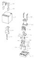
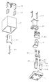
- FIG. 2 is an exploded perspective view of FIG. 1. It is a disassembled perspective view which shows the state which looked at FIG. 4 from the other side.
- A) is a perspective view which shows the state which looked at the base from the upper side
- (b) is a perspective view which shows the state which looked at the base from the downward side.
- A) is a perspective view which shows the state which looked at the base from the upper side
- (b) is a perspective view which shows the state which looked at the base from the downward side.
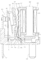
- FIG. 1 It is a disassembled perspective view of the electromagnet block and movable iron piece shown in FIG. It is sectional drawing at the time of contact closing which shows the state which removed the case from FIG. It is sectional drawing at the time of contact opening which shows the state which removed the case from FIG. It is an expansion perspective view of the contact opening-and-closing part of FIG. It is a graph which shows the attraction force curve by the electromagnet block of FIG. 4, and the change of the force which acts on a movable contact piece.
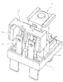
- This electromagnetic relay is generally a base 1 provided with an electromagnet block 2, a contact opening / closing part 3, and a movable iron piece 4 and covered with a case 5.
- the base 1 is formed in a rectangular shape in plan view by molding a synthetic resin material, and a first mounting portion 6 and a second mounting portion 7 are provided at two locations in the longitudinal direction.
- the direction extending in the longitudinal direction along the long side will be described as the X axis
- the direction extending in the short direction along the short side as the Y axis
- the direction extending in the height direction will be described as the Z axis.
- the first mounting portion 6 is for mounting an electromagnet block 2 to be described later, and a support recess 10 is formed in a recess 9 surrounded by the first peripheral wall 8 and the second mounting portion 7.
- a pair of coil terminal holes 11 penetrating the upper and lower surfaces are formed on both sides of the support recess 10 (short direction of the base 1: YY ′ direction).
- a guide portion 12 is formed in the vicinity of the support recess 10 (in the longitudinal direction of the base 1).
- the guide portion 12 includes a pair of guide walls 13 provided corresponding to the short direction (YY ′ direction) and an insulating wall 14 connecting them.
- Guide grooves 15 extending in the vertical direction are formed on the opposing surface of the guide wall 13.
- Both guide grooves 15 guide both side portions of a yoke 41 described later.
- a guide recess 16 is formed at the center of the region surrounded by the guide wall 13 and the insulating wall 14.
- a guided portion 50 of a hinge spring 44 described later is located in the guide recess 16.
- the second mounting portion 7 is for mounting the contact opening / closing portion 3, and a pedestal portion 17 having the same height as the first peripheral wall 8 of the first mounting portion 6 is formed.
- the base portion 17 is formed with a slit-shaped first terminal hole 18 extending in the YY ′ direction.
- the first terminal hole 18 penetrates only at two communicating portions 19 on both sides on the bottom surface of the base 1, and a movable contact piece 52 described later is press-fitted.
- a second peripheral wall 20 is formed from three sides of the pedestal portion 17 excluding the first mounting portion side.
- a portion constituting the X ′ direction side of the second peripheral wall 20 has a large thickness, and a pair of second terminal holes 21 each having a slit shape extending in the YY ′ direction are formed therein.
- a fixed contact piece 51 (described later) is press-fitted and fixed in each second terminal hole 21.
- Electromagnet block 2 As shown in FIGS. 7 and 8, the electromagnet block 2 is obtained by winding a coil 24 around an iron core 22 via a spool 23.
- the iron core 22 is made of a magnetic material in a rod shape, and a bowl-shaped magnetic pole portion 25 is formed at a lower end portion, and a yoke 41 is caulked and fixed at the upper end portion.
- the spool 23 is obtained by molding a synthetic resin material, and has a cylindrical body portion 27 that forms a center hole 26, and flange portions (upper end side flange portion 28 and lower end side flange portion) formed at both upper and lower ends thereof. Part 29).
- the upper end side flange 28 has a relief groove 30 formed on the upper surface, and a central hole 26 is opened there. One end of a yoke 41 described later is disposed in the escape groove 30. A central hole 26 is opened in the lower end side flange 29, from which the iron core 22 can be inserted.
- Terminal attachment portions 31 are provided on both side portions of the lower end side flange portion 29, and terminal holding holes 32 are respectively formed therein.
- a coil terminal 36 to be described later is press-fitted and fixed in each terminal holding hole 32.
- Step portions 33 are respectively formed on both sides of one end of the terminal attachment portion 31, and coil winding portions 39 of the coil terminals 36 press-fitted and fixed in the terminal holding holes 32 are respectively projected.
- a guide groove 34 that extends from the body portion 27 to the side end surface and communicates with the one step portion 33 is formed in the lower end side flange portion 29.
- One end side (winding start side) of the coil 24 wound around the body portion 27 is disposed in the guide groove 34, and is wound around the coil winding portion 39 of the coil terminal 36 protruding from the step portion 33.
- a pair of guide protrusions 35 are provided at a predetermined interval on the bottom surface of the lower end side flange 29. These guide protrusions 35 are positioned in the support recess 10 of the base 1 and serve to position the spool 23, that is, the electromagnet block 2 with respect to the base 1.
- the coil terminal 36 is made of a conductive material in a flat plate shape, and its lower end is formed so that its width and thickness gradually decrease as it goes downward.
- a press-fit portion 37 bulging from one surface is formed by pressing at the upper end portion of the coil terminal 36, and an upper portion thereof is a wide portion 38.
- a coil winding portion 39 protrudes from one end of the wide portion 38.
- the coil 24 is wound around the body portion 27 of the spool 23, and then an insulating sheet 40 is adhered to the outer peripheral surface thereof.
- One end of the coil 24 is disposed in the guide groove 34 of the spool 23. After winding the spool 23 around the body 27, both ends are wound around the coil winding portions 39 of the respective coil terminals 36, and then soldered. Attached.
- a yoke 41 is fastened and fixed to one end of the iron core 22.
- the yoke 41 is formed by bending a magnetic material into a substantially L shape.
- an opening 41a for inserting and fixing the one end of the iron core 22 is formed.
- the other end of the yoke 41 is wide, and protrusions 42 are formed on both sides of the lower end.
- a movable iron piece 4 which will be described later is located between the projecting portions 42, and one corner portion functions as a fulcrum that rotatably supports the movable iron piece 4.
- caulking projections 43 are formed at two locations, upper and lower.
- a hinge spring 44 is caulked and fixed to the intermediate portion of the yoke 41 using the protrusion 43.
- the method of fixing the hinge spring 44 to the yoke 41 is not limited to caulking, and other methods such as ultrasonic welding, resistance welding, and laser welding may be used.
- the hinge spring 44 includes a connecting portion 45 that is in surface contact with the outer surface of the intermediate portion of the yoke 41.
- the connecting portion 45 is formed with through holes 45a at two locations, and the projections 43 of the yoke 41 are inserted and crimped.
- the upper portion of the connecting portion 45 is an elastic contact portion 46 that extends at a predetermined angle so as to gradually move away from the outer surface of the intermediate portion of the yoke 41.
- the elastic contact portion 46 is capable of elastic contact with a press receiving portion of a card member 65 provided on the movable iron piece 4 described later. The elastic contact portion 46 mitigates the occurrence of a collision sound when the movable iron piece 4 moves back to the original position.
- a lower portion of the connecting portion 45 has a first inclined portion 47 extending at a predetermined angle so as to gradually move away from the outer surface of the intermediate portion of the yoke 41, and a predetermined angle so as to gradually approach the yoke side from the first inclined portion 47.
- the elastic support portion 49 is composed of a second inclined portion 48 extending at the end. The elastic support part 49 press-contacts the movable iron piece 4 which the 2nd inclination part 48 mentions later, and elastically supports the movable iron piece 4 so that rotation is possible.
- the lower part of the elastic support part 49 is a guided part 50 extending vertically downward in a state in which the movable iron piece 4 is elastically supported by the elastic support part 49.
- the guided portion 50 is disposed in the guide recess 16 formed in the first mounting portion 6 of the base 1, and the hinge spring 44 is prevented from being displaced by being guided by the guide recess 16.
- the contact opening / closing part 3 is composed of a fixed contact piece 51 and a movable contact piece 52 obtained by pressing a conductive material such as copper into a plate shape.
- the fixed contact piece 51 includes a press-fit portion 53, a terminal portion 54 that extends downward from the press-fit portion 53, and a contact piece portion 55 that extends upward from the press-fit portion 53.
- the press-fitting portion 53 is formed with a bulging portion 56 that bulges from one side by press working.
- the bulging portion 56 can be press-fitted into the second terminal hole 21 of the base 1.
- the terminal portion 54 is narrower than the press-fit portion 53 and is formed so that its position is shifted to one side.
- the contact piece portion 55 is formed on the opposite side to the terminal portion 54 and has a width dimension that is substantially half that of the press-fit portion 53.
- a through hole is formed in the upper end portion of the contact piece portion 55, and a fixed contact 57 is fixed by caulking there.
- the movable contact piece 52 includes a press-fit portion 58 and a pair of contact piece portions 59 that extend from both sides of the press-fit portion 58 upward.
- the press-fit portion 58 is formed with a bulging portion 60 extending in the width direction at the center in the vertical direction, and can be press-fit into the first terminal hole 18 of the base 1.
- a pair of projections 61 projecting downward are formed at both ends of the lower edge of the press-fit portion 58.
- the contact piece portion 59 is bent and extends in the vicinity of the press-fitting portion 58, and a through hole 59a is formed in the upper end portion, and the movable contact 62 is fixed by crimping thereto.
- the movable contact piece 52 can be brought into and out of contact with the fixed contact 57 of the fixed contact piece 51 press-fitted into the second terminal hole 21 while the press-fit portion 58 is press-fitted into the first terminal hole 18 of the base 1. To face.
- the movable iron piece 4 is formed by pressing a plate-like magnetic material into a substantially L shape by pressing.
- One end of the movable iron piece 4 is a sucked portion 63 that is attracted to the magnetic pole portion 25 of the iron core 22.
- the tip portion and the base portion of the sucked portion 63 are narrow, and interference between the guide protrusion 35 formed on the bottom surface of the spool 23 and the protrusion 42 formed on the lower end portion of the yoke 41 is avoided.
- An opening 64 is formed on the other end side of the movable iron piece 4.
- a hinge spring 44 is inserted through the opening 64 and is in pressure contact with a corner of the sucked portion 63.
- the other end of the movable iron piece 4 is narrow, and a card member 65 is integrated above the opening 64.
- the card member 65 is made of a synthetic resin material.
- a first protrusion 66 formed on both sides of the upper end portion of the movable iron piece 4 and on the upper side.
- a second protrusion 67 to be formed is formed.
- a protruding pressing portion 69 is formed at the upper end portion of the protrusion 68 so that the upper end portion of the contact piece portion 55 of the movable contact piece 52 can be pressed.
- a shielding wall 70 that protrudes from the other surface and extends further downward is formed.
- the case 5 is made of a synthetic resin material in a box shape with an open bottom surface. Sealing holes 71 are formed in the upper corners of the case 5. The sealing hole 71 is thermally sealed after sealing the fitting portion between the base 1 and the case 5.
- slit-like recesses 72 are formed on both sides and the center. A recess 73 that is recessed from the upper surface is formed between each of the 72, and a protrusion 74 is formed at the center of the upper surface.
- the arc extinguishing member 75 is attached to the case 5 using the recess 72 and the recess 73.
- the arc extinguishing member 75 includes a pair of permanent magnets 76 arranged at a predetermined interval to extinguish the arc, and a connecting member 77 made of a magnetic material for magnetically connecting the permanent magnets 76. Yes.
- the permanent magnet 76 has a substantially rectangular parallelepiped shape, and is arranged so that the opposing surfaces have different polarities when attached to the inner surfaces of the opposing walls 78 of the connecting member 77.
- the polarity of the facing surface may be set so that the direction of the force acting on the arc current is directed to the intermediate wall 79 side of the connecting member 77 described later according to the difference in the direction of current flow between the contacts.
- the connecting member 77 is obtained by bending a plate-like magnetic material by pressing so that both end sides face each other.
- a permanent magnet 76 is attracted and fixed to the inner surface of each opposing wall 78 by its own magnetic force.
- the intermediate wall 79 of the connecting member 77 is formed with intermediate protrusions 80 positioned between the opposing walls 78 by cutting both sides from different end sides.
- Each intermediate projecting portion 80 is located at the center of both opposing walls 78, and plays a role of shortening the magnetic path by projecting between both contact opening / closing positions. That is, the magnetic flux generated from each permanent magnet 76 forms a closed loop with a magnetic circuit that passes through the intermediate wall 79 and each opposing wall 78 via the intermediate protrusion 80 and returns to the permanent magnet 76.
- the arc extinguishing member 75 not only a pair of permanent magnets 76 but also a connecting member 77 for magnetically connecting them is provided. For this reason, a magnetic circuit is formed and magnetic flux leakage hardly occurs. Further, by providing the intermediate protrusion 80, the magnetic path can be set short. Therefore, it is possible to increase the magnetic efficiency. As a result, even if an arc is generated at the time of opening and closing the contact, the arc is extended to the side by the Fleming left-hand rule and extinguished in a short time.
- the coil 24 is wound around the body portion 27 of the spool 23, and the coil terminal 36 is press-fitted and fixed to the lower end side flange portion 29. Both ends of the coil 24 are wound around the coil winding portion 39 and soldered. Further, the iron core 22 is inserted into the center hole 26 of the spool 23 from the lower end side, and a yoke 41 to which a hinge spring 44 is attached in advance is fixed by caulking to a portion protruding from the upper end. Thereby, the electromagnet block 2 is completed.
- the completed electromagnet block 2 supports the movable iron piece 4 rotatably at the lower end portion of the yoke 41 using a hinge spring 44.
- the first protruding portion 66 of the card member 65 integrated with the movable iron piece 4 can come into contact with the yoke 41, and the elastic contact portion 46 of the hinge spring 44 is brought into contact with the second protruding portion 67 of the card member 65. It is possible to contact and separate.
- the electromagnet block 2 to which the movable iron piece 4 is attached and the contact opening / closing part 3 are mounted on the base 1.
- the coil terminal 36 is press-fitted into the coil terminal hole 11 of the base 1, and both side portions of the yoke 41 are inserted into the guide grooves 15 of the guide wall 13.
- the guide protrusion 35 is positioned in the support recess 10 and the electromagnet block 2 is positioned in the YY ′ direction.
- the lower end surface of the projecting portion 42 of the yoke 41 and the bottom surface of the terminal attachment portion 31 are in contact with the bottom surface of the recess 9 of the base 1.
- a gap is formed between the bottom surface of the recess 9 of the base 1 and the bottom surface of the lower end side flange portion 29 of the spool 23 so that the movable iron piece 4 can rotate.
- a shielding wall 70 of the card member 65 integrated with the movable iron piece 4 is disposed beyond the insulating wall 14 of the base 1. At this time, the insulating property between the electromagnet block 2 and the contact opening / closing part 3 is sufficiently secured by the guide wall 13 and the insulating wall 14 of the base 1, the upper part of the card member 65 and the shielding wall 70.
- the press-fitting part 58 of the movable contact piece 52 is press-fitted into the first terminal hole 18 of the base 1.
- the protrusion 61 is positioned at the communication portion 19, so that the mounting state of the movable contact piece 52 can be confirmed from the bottom surface of the base 1.
- the pressing portion 69 of the card member 65 previously mounted is pressed against the upper end portion of the movable contact piece 52, and the movable iron piece 4 has the attracted portion 63 as a magnetic pole portion of the iron core 22 due to the elastic force of the movable contact piece 52.
- the terminal portion 54 of the fixed contact piece 51 is inserted into the second terminal hole 21 of the base 1, and the press-fit portion 53 is press-fitted and fixed.
- the fixed contact piece 51 faces the movable contact piece 52 at a predetermined interval, and the movable contact 62 can be brought into contact with and separated from the fixed contact 57.
- the arc extinguishing member 75 is attached to the case 5.
- the permanent magnet 76 is attached to the opposing wall 78 of the connecting member 77, and the concave wall 72 formed in the case 5 is connected to the opposing wall 78 and the permanent magnet 76 of the connecting member 77.
- the protrusions 80 are respectively inserted. Then, the case 5 to which the arc extinguishing member 75 is attached is put on the base 1, and the fitting portion between both is sealed.
- the internal space may be sealed by heat sealing the sealing hole 71.
- the sealing hole 71 can be left open and the internal space can be used in communication with the surrounding atmosphere.
- the attracted portion 63 of the iron core 22 is centered on the fulcrum supported by the yoke 41 by the elastic force of the movable contact piece 52. It is located at an initial position away from the magnetic pole part 25. Therefore, the movable contact 62 maintains an open state separated from the fixed contact 57.
- the movable iron piece 4 When the coil 24 is energized and the electromagnet block 2 is excited, the movable iron piece 4 is attracted to the attracted portion 63 by the magnetic pole portion 25 of the iron core 22 and resists the urging force of the movable contact piece 52 as shown in FIG. Rotate. As a result, the movable contact piece 52 is elastically deformed, and the movable contact 62 is closed to the fixed contact 57 of the fixed contact piece 51.
- the movable iron piece 4 loses the attractive force of the iron core 22 and rotates by the elastic force of the movable contact piece 52.
- the second projecting portion 67 formed on the card member 65 of the movable iron piece 4 collides with the elastic contact portion 46 of the hinge spring 44.
- the second protrusion 67 is made of synthetic resin, and the elastic contact portion 46 is elastically deformed. And the contact state of the 2nd protrusion part 67 and the elastic contact part 46 is obtained early after the movable iron piece 4 starts rotation. Therefore, the collision sound hardly occurs.
- the first protrusion 66 made of synthetic resin contacts the intermediate portion of the yoke 41 while the movable contact piece 4 is further rotated to elastically deform the elastic contact portion 46. For this reason, the rotational speed of the movable iron piece 4 is reduced, and the generation of the collision sound is sufficiently suppressed here. As described above, the movable iron piece 4 smoothly returns to the initial position without generating a collision sound, and the movable contact 62 is separated from the fixed contact 57 and located at the open position.
- each magnetic circuit constitutes a closed loop, and there is almost no magnetic flux leakage to the surroundings.
- the presence of the intermediate protrusion 80 can effectively apply a magnetic force to the contact open / close position, that is, the arc generated between the contacts.
- a force acts on the generated arc in a direction orthogonal to the contact opening direction, and this arc is greatly extended, so that the arc is extinguished rapidly.
- the movable contact piece 52 is configured to open and close between the two fixed contact pieces 51, the arc current at the time of opening the contact flows in the direction shown in FIG.
- the magnetic poles of the permanent magnet 76 are set so as to have different polarities on the opposing surface so that a magnetic flux direction that can be deformed is obtained. That is, the arc is more reliably extinguished by deforming the arc toward the intermediate wall side of the connecting member 77. Therefore, if the configuration of the contact opening / closing part 3 is different, the magnetic pole of the permanent magnet 76 may be set according to the difference.
- the operating voltage of the electromagnet block 2 can be adjusted as follows. That is, the operating voltage of the electromagnet block 2 can be suppressed by changing the inclination angle of the elastic contact portion 46 of the hinge spring 44. Specifically, when the inclination angle of the elastic contact portion 46 with respect to the yoke 41 is increased, the magnetic field generated from the magnetic pole portion 25 of the iron core 22 acts on the attracted portion 63 of the movable iron piece 4 as shown in the graph of FIG. The position of the operating point can be changed with respect to a change in force (suction force curve). That is, by increasing the inclination angle of the elastic contact portion 46, it is possible to suppress the force required until the elastic contact portion 46 contacts the first protrusion 66 after the contact is opened. As a result, the operating voltage of the electromagnet block 2 can be suppressed so that the attractive force curve changes at a position smaller than that shown in the figure.
- the movable contact piece 52 is composed of a pair of contact pieces extending from the press-fit portion 37, but may be composed of two members (two movable contact pieces 52).
- the fixed contact piece 51 is composed of two members, it may be a continuous and integral structure similar to the movable contact piece 52.
- the combination of the movable contact piece 52 and the fixed contact piece 51 may be one set or three or more sets.
- Press-fitting portion 59 ... Contact piece portion 60 ... Expanded portion 61 ... Protrusion 62 ... Moving contact 63 ... Suctioned portion 64 ... Opening portion 65 ... Card member 66 ... First projecting portion 67 ... Second projecting portion 68 ... Projection Part 69 ... Pressing part 70 ... Shielding wall 71 ... Sealing hole 72 ... Slit 73 ... Recess 74 ... Protrusion 75 ... Arc extinguishing member 76 ... Permanent magnet 77 ... Connecting member 78 ... Counter wall 79 ... Intermediate wall 80 ... Intermediate protrusion Part
Landscapes
- Physics & Mathematics (AREA)
- Electromagnetism (AREA)
- Electromagnets (AREA)
Abstract
Description
ベース上に、棒状の鉄心の外周側にスプールを介してコイルを巻回し、前記鉄心の一端部に一端部を固定したヨークの他端部を前記鉄心の他端側の磁極部の側方まで伸長してなる電磁石ブロックを、前記鉄心の磁極部がベース側に隙間を有するようにして配置し、前記ヨークにヒンジバネを固定し、前記ヨークの他端部を支点として前記ヒンジバネの弾性支持部によって支持した状態で回動可能に可動鉄片を設け、前記電磁石ブロックを励磁し、前記鉄心の磁極部に前記可動鉄片の被吸引部を吸引して回動させることにより接点開閉部を駆動するようにした電磁継電器であって、
前記ヒンジバネは、前記ヨークへの固定位置から前記弾性支持部とは反対側に延びる弾性当接部を備え、
前記可動鉄片は、前記支点を挟んで前記被吸引部とは反対側に、前記ヨークに当接する前に前記弾性当接部に当接可能なカード部材を一体化したものである。
前記ヒンジバネの弾性当接部は、前記カード部材と前記ヨークとの間に配置するのが好ましい。
前記ベースは、前記ヒンジバネの被ガイド部が配置され、前記ヒンジバネの位置ずれを防止する支持凹部を備えるのが好ましい。
図1から図5は、本実施形態に係る電磁継電器を示す。この電磁継電器は、大略、ベース1に、電磁石ブロック2、接点開閉部3、及び、可動鉄片4を設け、ケース5を被せたものである。
ベース1は、図6に示すように、合成樹脂材料を成形加工することにより平面視矩形状に形成され、長手方向の2箇所には、第1装着部6と第2装着部7が設けられている(以下、長辺に沿って長手方向に延びる方向をX軸、短辺に沿って短手方向に延びる方向をY軸、高さ方向に延びる方向をZ軸として説明する)。
電磁石ブロック2は、図7及び図8に示すように、鉄心22にスプール23を介してコイル24を巻回したものである。
ヨーク41は、磁性材料を略L字形となるように折り曲げたものである。ヨーク41の一端部には、前記鉄心22の一端部を挿通して加締固定するための開口部41aが形成されている。ヨーク41の他端部は幅広となって、その下端部両側には突出部42がそれぞれ形成されている。両突出部42の間には、後述する可動鉄片4が位置し、一方の角部が可動鉄片4を回動可能に支持する支点として機能している。ヨーク41の中間部外面には、上下2箇所に加締用の突起43が形成されている。
接点開閉部3は、図4及び図5に示すように、銅等の導電性材料を板状にプレス加工した、固定接触片51と可動接触片52とで構成されている。
可動鉄片4は、図7及び図8に示すように、板状の磁性材料をプレス加工により略L字形に形成したものである。可動鉄片4の一端側は、鉄心22の磁極部25に吸引される被吸引部63である。被吸引部63の先端部及び基部は幅狭となっており、スプール23の底面に形成したガイド突部35と、ヨーク41の下端部に形成した突出部42との干渉がそれぞれ回避されている。可動鉄片4の他端側には開口部64が形成されている。開口部64にはヒンジバネ44が挿通し、被吸引部63の角部に圧接している。可動鉄片4の他端部は幅狭となっており、又、開口部64の上方側にはカード部材65が一体化されている。
ケース5は、図2に示すように、合成樹脂材料を下面が開口する箱状としたものである。ケース5の上面角部には密閉用孔71が形成されている。密閉用孔71は、ベース1とケース5の嵌合部分のシール後に熱封止される。ケース5の上面縁部(密閉用孔71と反対側)には、両側及び中央部にスリット状の凹部72がそれぞれ形成されている。各及ぶ72の間には、上面よりも窪んだ凹所73が形成されており、その上面中央部には突起74がそれぞれ形成されている。
続いて、前記構成からなる電磁継電器の組立方法について説明する。
次に、前記構成からなる電磁継電器の動作について説明する。
すなわち、ヒンジバネ44の弾性当接部46の傾斜角度を変更することにより、電磁石ブロック2の動作電圧を抑えることが可能となる。詳しくは、ヨーク41に対する弾性当接部46の傾斜角度を大きくすると、図12のグラフに示すように、鉄心22の磁極部25から発生させた磁界により可動鉄片4の被吸引部63に作用する力の変化(吸引力曲線)に対して、動作点の位置を変更することができる。つまり、弾性当接部46の傾斜角度を大きくすることにより、接点が開放してから第1突出部66に弾性当接部46が当接するまでに必要となる力を抑えることができる。この結果、吸引力曲線が、図示されるものよりも小さい位置で変化するように、電磁石ブロック2の動作電圧を抑制することが可能となる。
なお、本発明は、前記実施形態に記載された構成に限定されるものではなく、種々の変更が可能である。
2…電磁石ブロック
3…接点開閉部
4…可動鉄片
5…ケース
6…第1装着部
7…第2装着部
8…第1周縁壁
9…凹所
10…支持凹部
11…コイル端子孔
12…ガイド部
13…ガイド壁
14…絶縁壁
15…ガイド溝
16…ガイド凹部
17…台座部
18…第1端子孔
19…連通部
20…第2周縁壁
21…第2端子孔
22…鉄心
23…スプール
24…コイル
25…磁極部
26…中心孔
27…胴部
28…上端側鍔部
29…下端側鍔部
30…逃がし溝
31…端子取付部
32…端子保持孔
33…段部
34…案内溝
35…ガイド突部
36…コイル端子
37…圧入部
38…幅広部
39…コイル巻付部
40…絶縁シート
41…ヨーク
42…突出部
43…突起
44…ヒンジバネ
45…接続部
46…弾性当接部
47…第1傾斜部
48…第2傾斜部
49…弾性支持部
50…被ガイド部
51…固定接触片
52…可動接触片
53…圧入部
54…端子部
55…接触片部
56…膨出部
57…固定接点
58…圧入部
59…接触片部
60…膨出部
61…突起
62…可動接点
63…被吸引部
64…開口部
65…カード部材
66…第1突出部
67…第2突出部
68…突条部
69…押圧部
70…遮蔽壁
71…密閉用孔
72…スリット
73…凹所
74…突起
75…アーク消弧部材
76…永久磁石
77…接続部材
78…対向壁
79…中間壁
80…中間突出部
Claims (5)
- ベース上に、棒状の鉄心の外周側にスプールを介してコイルを巻回し、前記鉄心の一端部に一端部を固定したヨークの他端部を前記鉄心の他端側の磁極部の側方まで伸長してなる電磁石ブロックを、前記鉄心の磁極部がベース側に隙間を有するようにして配置し、前記ヨークにヒンジバネを固定し、前記ヨークの他端部を支点として前記ヒンジバネの弾性支持部によって支持した状態で回動可能に可動鉄片を設け、前記電磁石ブロックを励磁し、前記鉄心の磁極部に前記可動鉄片の被吸引部を吸引して回動させることにより接点開閉部を駆動するようにした電磁継電器であって、
前記ヒンジバネは、前記ヨークへの固定位置から前記弾性支持部とは反対側に延びる弾性当接部を備え、
前記可動鉄片は、前記支点を挟んで前記被吸引部とは反対側に、前記ヨークに当接する前に前記弾性当接部に当接可能なカード部材を一体化したことを特徴とする電磁継電器。 - 前記カード部材を一体化した可動鉄片は、ベース上に配置した電磁石ブロックのヨークの高さ寸法以下の領域に配置され、
前記ヒンジバネの弾性当接部は、前記カード部材と前記ヨークとの間に配置したことを特徴とする請求項1に記載の電磁継電器。 - 前記カード部材は、前記ヒンジバネの弾性当接部に当接可能な第1突出部を備えたことを特徴とする請求項1又は2に記載の電磁継電器。
- 前記カード部材は、前記第1突出部が前記ヒンジバネの弾性当接部に当接した後、前記ヨークに当接する第2突出部を備えたことを特徴とする請求項3に記載の電磁継電器。
- 前記ヒンジバネは、前記可動鉄片の支持位置に対して前記ヨークへの固定位置とは反対側に被ガイド部を備え、
前記ベースは、前記ヒンジバネの被ガイド部が配置され、前記ヒンジバネの位置ずれを防止する支持凹部を備えたことを特徴とする請求項1から4のいずれか1項に記載の電磁継電器。
Priority Applications (4)
| Application Number | Priority Date | Filing Date | Title |
|---|---|---|---|
| KR1020137004079A KR101436268B1 (ko) | 2011-03-14 | 2011-03-24 | 전자 계전기 |
| EP11860866.0A EP2688082B1 (en) | 2011-03-14 | 2011-03-24 | Electromagnetic relay |
| CN201180066414.9A CN103339706B (zh) | 2011-03-14 | 2011-03-24 | 电磁继电器 |
| US13/981,314 US9123494B2 (en) | 2011-03-14 | 2011-03-24 | Electromagnetic relay |
Applications Claiming Priority (2)
| Application Number | Priority Date | Filing Date | Title |
|---|---|---|---|
| JP2011-055721 | 2011-03-14 | ||
| JP2011055721A JP4883232B1 (ja) | 2011-03-14 | 2011-03-14 | 電磁継電器 |
Publications (1)
| Publication Number | Publication Date |
|---|---|
| WO2012124165A1 true WO2012124165A1 (ja) | 2012-09-20 |
Family
ID=45851248
Family Applications (1)
| Application Number | Title | Priority Date | Filing Date |
|---|---|---|---|
| PCT/JP2011/057133 WO2012124165A1 (ja) | 2011-03-14 | 2011-03-24 | 電磁継電器 |
Country Status (6)
| Country | Link |
|---|---|
| US (1) | US9123494B2 (ja) |
| EP (1) | EP2688082B1 (ja) |
| JP (1) | JP4883232B1 (ja) |
| KR (1) | KR101436268B1 (ja) |
| CN (1) | CN103339706B (ja) |
| WO (1) | WO2012124165A1 (ja) |
Cited By (4)
| Publication number | Priority date | Publication date | Assignee | Title |
|---|---|---|---|---|
| CN103985605A (zh) * | 2013-02-13 | 2014-08-13 | 欧姆龙株式会社 | 电磁继电器 |
| EP2768004A1 (en) * | 2013-02-13 | 2014-08-20 | Omron Corporation | Electromagnetic relay |
| WO2016013485A1 (ja) * | 2014-07-23 | 2016-01-28 | 富士通コンポーネント株式会社 | 電磁継電器 |
| JP2016025040A (ja) * | 2014-07-23 | 2016-02-08 | 富士通コンポーネント株式会社 | 電磁継電器 |
Families Citing this family (23)
| Publication number | Priority date | Publication date | Assignee | Title |
|---|---|---|---|---|
| CN105359243B (zh) * | 2013-06-28 | 2018-06-05 | 松下知识产权经营株式会社 | 触点装置以及搭载有该触点装置的电磁继电器 |
| JP6341361B2 (ja) * | 2013-12-13 | 2018-06-13 | パナソニックIpマネジメント株式会社 | 電磁リレー |
| JP6433706B2 (ja) | 2014-07-28 | 2018-12-05 | 富士通コンポーネント株式会社 | 電磁継電器及びコイル端子 |
| EP2996137B1 (en) * | 2014-09-10 | 2019-05-08 | Tyco Electronics EC Trutnov s.r.o. | Yoke assembly with deceleration element for switching device and same |
| KR101638949B1 (ko) * | 2014-10-27 | 2016-07-12 | 대성전기공업 주식회사 | 릴레이 장치 |
| KR101671819B1 (ko) * | 2014-10-29 | 2016-11-02 | 대성전기공업 주식회사 | 스톱퍼를 구비한 코어 이동형 외팔보 타입 릴레이 장치 |
| KR101671821B1 (ko) * | 2014-10-29 | 2016-11-16 | 엘에스오토모티브 주식회사 | 릴레이 장치 |
| KR101644945B1 (ko) * | 2014-10-29 | 2016-08-02 | 대성전기공업 주식회사 | 릴레이 장치 |
| KR101681966B1 (ko) * | 2014-10-29 | 2016-12-02 | 엘에스오토모티브 주식회사 | 코어 이동형 외팔보 타입 릴레이 장치 |
| KR101671820B1 (ko) * | 2014-10-29 | 2016-11-02 | 대성전기공업 주식회사 | 릴레이 장치 |
| KR101671814B1 (ko) * | 2014-10-29 | 2016-11-02 | 대성전기공업 주식회사 | 플런저를 구비한 코어 이동형 외팔보 타입 릴레이 장치 |
| KR101677928B1 (ko) * | 2014-10-30 | 2016-11-21 | 엘에스오토모티브 주식회사 | 릴레이 장치 |
| JP6657692B2 (ja) * | 2015-09-11 | 2020-03-04 | オムロン株式会社 | 電磁石装置およびこれを用いた電磁継電器 |
| KR101660864B1 (ko) * | 2016-06-20 | 2016-09-28 | 대성전기공업 주식회사 | 릴레이 장치 |
| JP2018006209A (ja) * | 2016-07-05 | 2018-01-11 | 富士通コンポーネント株式会社 | 電磁継電器 |
| DE102016117671A1 (de) * | 2016-09-20 | 2018-03-22 | Panasonic Industrial Devices Europe Gmbh | Elektromagnetisches Relais |
| JP6959728B2 (ja) * | 2016-11-04 | 2021-11-05 | 富士通コンポーネント株式会社 | 電磁継電器 |
| JP6737167B2 (ja) * | 2016-12-21 | 2020-08-05 | アンデン株式会社 | 電磁継電器 |
| JP6836241B2 (ja) * | 2016-12-27 | 2021-02-24 | 富士通コンポーネント株式会社 | 電磁継電器 |
| CN108565180A (zh) * | 2018-05-24 | 2018-09-21 | 深圳巴斯巴汽车电子有限公司 | 高压直流继电器 |
| USD923586S1 (en) | 2018-12-17 | 2021-06-29 | Omron Corporation | Terminal block |
| JP2021144916A (ja) | 2020-03-13 | 2021-09-24 | オムロン株式会社 | 電磁継電器 |
| EP4002416B1 (en) * | 2020-11-16 | 2023-09-13 | Xiamen Hongfa Electroacoustic Co., Ltd. | Electromagnetic relay with an elastically deformable moving member |
Citations (4)
| Publication number | Priority date | Publication date | Assignee | Title |
|---|---|---|---|---|
| JPS60156646U (ja) * | 1984-03-27 | 1985-10-18 | オムロン株式会社 | 電磁継電器 |
| JPH10255633A (ja) * | 1997-03-14 | 1998-09-25 | Matsushita Electric Works Ltd | 電磁リレー |
| JP2002245917A (ja) | 2001-02-13 | 2002-08-30 | Omron Corp | 電磁継電器 |
| JP2007200619A (ja) * | 2006-01-24 | 2007-08-09 | Matsushita Electric Works Ltd | 電磁リレー |
Family Cites Families (47)
| Publication number | Priority date | Publication date | Assignee | Title |
|---|---|---|---|---|
| US2735968A (en) * | 1956-02-21 | Relay structure | ||
| JPS538901B2 (ja) * | 1971-09-01 | 1978-04-01 | ||
| DE2912800C2 (de) * | 1979-03-30 | 1985-04-25 | Siemens AG, 1000 Berlin und 8000 München | Elektromagnetisches Relais für hohe Schaltleistungen |
| JPS60156646A (ja) * | 1984-01-25 | 1985-08-16 | Yoshitomi Pharmaceut Ind Ltd | パラヒドロキシ安息香酸化合物 |
| DE3403975A1 (de) * | 1984-02-04 | 1985-08-14 | Bayer Ag, 5090 Leverkusen | Verfahren zur herstellung von abs-formmassen mit verbessertem brandverhalten |
| DE3414731C2 (de) * | 1984-04-18 | 1986-03-20 | Hengstler GmbH, Geschäftsbereich Haller-Relais, 7209 Wehingen | Kleinstrelais |
| JPS60188454U (ja) * | 1984-05-25 | 1985-12-13 | 松下電工株式会社 | 低動作音電磁継電器 |
| JPS63149039U (ja) * | 1987-03-20 | 1988-09-30 | ||
| US4761627A (en) * | 1987-09-17 | 1988-08-02 | Potter And Brumfield Inc. | Electromagnetic relay including a rotatable armature mount |
| US4758809A (en) * | 1987-09-17 | 1988-07-19 | Potter And Brumfield Inc. | Electromagnetic relay having a multifunction retaining spring |
| DE3835118A1 (de) * | 1988-10-14 | 1990-04-19 | Siemens Ag | Elektromagnetisches relais |
| EP0372554A3 (en) * | 1988-12-09 | 1992-04-08 | OMRON Corporation | Electromagnetic relay |
| JPH0346728A (ja) * | 1989-07-13 | 1991-02-28 | Omron Corp | 電磁継電器 |
| JPH0469836U (ja) * | 1990-10-26 | 1992-06-19 | ||
| EP0501070B2 (en) * | 1991-02-27 | 2003-05-14 | Takamisawa Electric Co., Ltd. | Small sized electromagnetic relay |
| EP0579832B1 (en) * | 1991-04-09 | 1999-10-06 | Omron Corporation | Electromagnetic relay |
| JP3383984B2 (ja) * | 1992-05-14 | 2003-03-10 | オムロン株式会社 | 電磁継電器 |
| US5289144A (en) * | 1992-08-21 | 1994-02-22 | Potter & Brumfield, Inc. | Electromagnetic relay and method for assembling the same |
| DE4300594A1 (de) * | 1993-01-13 | 1994-07-14 | Hengstler Bauelemente | Sicherheitsrelais mit zwangsgeführtem Kontaktsatz und monostabilem Antrieb |
| US5321377A (en) * | 1993-01-21 | 1994-06-14 | Kaloust P. Sagoian | Electromagnet for relays and contactor assemblies |
| DE4405222C1 (de) * | 1994-02-18 | 1995-05-11 | Siemens Ag | Verfahren zur Herstellung eines Relais mit beweglichem Schieber und nach dem Verfahren hergestelltes Relais |
| JPH07254340A (ja) * | 1994-03-15 | 1995-10-03 | Omron Corp | 電磁継電器 |
| IT233985Y1 (it) * | 1994-07-29 | 2000-02-16 | Gavazzi Carlo Electromatic | Rele' elettromagnetico pluricontatto miniatura per usi industriali |
| JPH0869737A (ja) * | 1994-08-31 | 1996-03-12 | Daiichi Denki Kk | 小型継電器の消音装置 |
| US5864270A (en) * | 1995-03-21 | 1999-01-26 | Siemens Aktiengesellschaft | Electromagnetic relay |
| US5805040A (en) * | 1996-09-27 | 1998-09-08 | Simens Electromechanical Components, Inc. | Relay base and method of assembly |
| DE19804572A1 (de) * | 1997-05-05 | 1999-08-12 | Schrack Components Ag | Relais mit Kontaktfedern |
| DE19727991C1 (de) * | 1997-07-01 | 1998-11-19 | Schrack Components Ag | Elektromagnetisches Relais |
| US6211761B1 (en) * | 1997-09-10 | 2001-04-03 | Takamisawa Electric Co., Ltd. | Electromagnetic relay, joining structure for hinge spring and yoke in the electromagnetic relay, and flux penetration preventing structure |
| EP0938119A1 (de) * | 1998-02-18 | 1999-08-25 | ELESTA relays GmbH | Relais |
| US6486760B2 (en) * | 1998-12-07 | 2002-11-26 | Matsushita Electric Works, Ltd. | Electromagnetic relay |
| JP4212248B2 (ja) * | 2001-02-09 | 2009-01-21 | 富士通コンポーネント株式会社 | 電磁継電器 |
| JP4334158B2 (ja) * | 2001-03-26 | 2009-09-30 | 富士通コンポーネント株式会社 | 電磁継電器 |
| US6798322B2 (en) * | 2002-06-17 | 2004-09-28 | Tyco Electronics Corporation | Low noise relay |
| JP4168733B2 (ja) | 2002-11-12 | 2008-10-22 | オムロン株式会社 | 電磁継電器 |
| JP4131161B2 (ja) * | 2002-11-12 | 2008-08-13 | オムロン株式会社 | 電磁継電器 |
| JP4190379B2 (ja) * | 2003-09-12 | 2008-12-03 | 富士通コンポーネント株式会社 | 複合型電磁継電器 |
| JP4424260B2 (ja) * | 2005-06-07 | 2010-03-03 | オムロン株式会社 | 電磁リレー |
| JP4810937B2 (ja) * | 2005-09-06 | 2011-11-09 | オムロン株式会社 | 開閉装置 |
| JP4742954B2 (ja) * | 2006-03-31 | 2011-08-10 | オムロン株式会社 | 電磁継電器 |
| JP2008053152A (ja) * | 2006-08-28 | 2008-03-06 | Omron Corp | 静音型電磁継電器 |
| US7477119B2 (en) * | 2007-03-02 | 2009-01-13 | Good Sky Electric Co., Ltd. | Electromagnetic relay |
| JP4946559B2 (ja) * | 2007-03-22 | 2012-06-06 | オムロン株式会社 | 電磁継電器 |
| JP5058643B2 (ja) * | 2007-03-26 | 2012-10-24 | 富士通コンポーネント株式会社 | 電磁継電器 |
| JP5163318B2 (ja) * | 2008-06-30 | 2013-03-13 | オムロン株式会社 | 電磁石装置 |
| TW201019364A (en) * | 2008-11-12 | 2010-05-16 | Good Sky Electric Co Ltd | An electromagnetic relay |
| JP5624431B2 (ja) * | 2010-11-08 | 2014-11-12 | パナソニック株式会社 | 電磁リレー |
-
2011
- 2011-03-14 JP JP2011055721A patent/JP4883232B1/ja active Active
- 2011-03-24 WO PCT/JP2011/057133 patent/WO2012124165A1/ja active Application Filing
- 2011-03-24 CN CN201180066414.9A patent/CN103339706B/zh active Active
- 2011-03-24 EP EP11860866.0A patent/EP2688082B1/en active Active
- 2011-03-24 KR KR1020137004079A patent/KR101436268B1/ko active IP Right Grant
- 2011-03-24 US US13/981,314 patent/US9123494B2/en active Active
Patent Citations (4)
| Publication number | Priority date | Publication date | Assignee | Title |
|---|---|---|---|---|
| JPS60156646U (ja) * | 1984-03-27 | 1985-10-18 | オムロン株式会社 | 電磁継電器 |
| JPH10255633A (ja) * | 1997-03-14 | 1998-09-25 | Matsushita Electric Works Ltd | 電磁リレー |
| JP2002245917A (ja) | 2001-02-13 | 2002-08-30 | Omron Corp | 電磁継電器 |
| JP2007200619A (ja) * | 2006-01-24 | 2007-08-09 | Matsushita Electric Works Ltd | 電磁リレー |
Cited By (11)
| Publication number | Priority date | Publication date | Assignee | Title |
|---|---|---|---|---|
| CN103985605A (zh) * | 2013-02-13 | 2014-08-13 | 欧姆龙株式会社 | 电磁继电器 |
| US20140225689A1 (en) * | 2013-02-13 | 2014-08-14 | Omron Corporation | Electromagnetic relay |
| EP2768004A1 (en) * | 2013-02-13 | 2014-08-20 | Omron Corporation | Electromagnetic relay |
| CN104143478A (zh) * | 2013-02-13 | 2014-11-12 | 欧姆龙株式会社 | 电磁继电器 |
| US8928438B2 (en) | 2013-02-13 | 2015-01-06 | Omron Corporation | Electromagnetic relay |
| US9142373B2 (en) * | 2013-02-13 | 2015-09-22 | Omron Corporation | Electromagnetic relay |
| KR20150135177A (ko) * | 2013-02-13 | 2015-12-02 | 오므론 가부시키가이샤 | 전자 계전기 |
| KR101656628B1 (ko) * | 2013-02-13 | 2016-09-09 | 오므론 가부시키가이샤 | 전자 계전기 |
| WO2016013485A1 (ja) * | 2014-07-23 | 2016-01-28 | 富士通コンポーネント株式会社 | 電磁継電器 |
| JP2016025040A (ja) * | 2014-07-23 | 2016-02-08 | 富士通コンポーネント株式会社 | 電磁継電器 |
| US9865420B2 (en) | 2014-07-23 | 2018-01-09 | Fujitsu Component Limited | Electromagnetic relay |
Also Published As
| Publication number | Publication date |
|---|---|
| EP2688082A1 (en) | 2014-01-22 |
| KR20130041218A (ko) | 2013-04-24 |
| CN103339706A (zh) | 2013-10-02 |
| US9123494B2 (en) | 2015-09-01 |
| EP2688082A4 (en) | 2014-10-29 |
| EP2688082B1 (en) | 2019-04-17 |
| JP4883232B1 (ja) | 2012-02-22 |
| KR101436268B1 (ko) | 2014-08-29 |
| CN103339706B (zh) | 2016-10-12 |
| JP2012190763A (ja) | 2012-10-04 |
| US20140015628A1 (en) | 2014-01-16 |
Similar Documents
| Publication | Publication Date | Title |
|---|---|---|
| JP4883232B1 (ja) | 電磁継電器 | |
| JP5085754B2 (ja) | 電磁継電器 | |
| JP5923932B2 (ja) | 接点開閉機構及び電磁継電器 | |
| JP5741338B2 (ja) | 端子部材のシール構造、及び、電磁継電器 | |
| USRE48964E1 (en) | Electromagnetic relay | |
| KR101435349B1 (ko) | 전자 계전기 | |
| JP5085755B2 (ja) | 電磁継電器 | |
| JP4586861B2 (ja) | 電磁継電器 | |
| JP2012212668A (ja) | 接点装置及び電磁開閉器 | |
| JP2009199893A (ja) | 電磁継電器 | |
| JP2014203784A (ja) | 接点装置およびそれを用いた電磁リレー | |
| WO2020162279A1 (ja) | 電磁石装置 | |
| JP2004335150A (ja) | 電磁継電器 | |
| JPH10214552A (ja) | 電磁リレー |
Legal Events
| Date | Code | Title | Description |
|---|---|---|---|
| 121 | Ep: the epo has been informed by wipo that ep was designated in this application |
Ref document number: 11860866 Country of ref document: EP Kind code of ref document: A1 |
|
| ENP | Entry into the national phase |
Ref document number: 20137004079 Country of ref document: KR Kind code of ref document: A |
|
| WWE | Wipo information: entry into national phase |
Ref document number: 2011860866 Country of ref document: EP |
|
| NENP | Non-entry into the national phase |
Ref country code: DE |
|
| WWE | Wipo information: entry into national phase |
Ref document number: 13981314 Country of ref document: US |