WO2012124101A1 - Boîtier de dispositif électronique - Google Patents
Boîtier de dispositif électronique Download PDFInfo
- Publication number
- WO2012124101A1 WO2012124101A1 PCT/JP2011/056384 JP2011056384W WO2012124101A1 WO 2012124101 A1 WO2012124101 A1 WO 2012124101A1 JP 2011056384 W JP2011056384 W JP 2011056384W WO 2012124101 A1 WO2012124101 A1 WO 2012124101A1
- Authority
- WO
- WIPO (PCT)
- Prior art keywords
- reactor
- case
- vibration
- rib
- converter
- Prior art date
Links
Images


Classifications
-
- H—ELECTRICITY
- H05—ELECTRIC TECHNIQUES NOT OTHERWISE PROVIDED FOR
- H05K—PRINTED CIRCUITS; CASINGS OR CONSTRUCTIONAL DETAILS OF ELECTRIC APPARATUS; MANUFACTURE OF ASSEMBLAGES OF ELECTRICAL COMPONENTS
- H05K5/00—Casings, cabinets or drawers for electric apparatus
- H05K5/02—Details
- H05K5/0217—Mechanical details of casings
-
- H—ELECTRICITY
- H02—GENERATION; CONVERSION OR DISTRIBUTION OF ELECTRIC POWER
- H02K—DYNAMO-ELECTRIC MACHINES
- H02K5/00—Casings; Enclosures; Supports
- H02K5/24—Casings; Enclosures; Supports specially adapted for suppression or reduction of noise or vibrations
-
- H—ELECTRICITY
- H01—ELECTRIC ELEMENTS
- H01F—MAGNETS; INDUCTANCES; TRANSFORMERS; SELECTION OF MATERIALS FOR THEIR MAGNETIC PROPERTIES
- H01F27/00—Details of transformers or inductances, in general
- H01F27/02—Casings
-
- H—ELECTRICITY
- H01—ELECTRIC ELEMENTS
- H01F—MAGNETS; INDUCTANCES; TRANSFORMERS; SELECTION OF MATERIALS FOR THEIR MAGNETIC PROPERTIES
- H01F27/00—Details of transformers or inductances, in general
- H01F27/24—Magnetic cores
- H01F27/26—Fastening parts of the core together; Fastening or mounting the core on casing or support
- H01F27/266—Fastening or mounting the core on casing or support
-
- H—ELECTRICITY
- H01—ELECTRIC ELEMENTS
- H01F—MAGNETS; INDUCTANCES; TRANSFORMERS; SELECTION OF MATERIALS FOR THEIR MAGNETIC PROPERTIES
- H01F27/00—Details of transformers or inductances, in general
- H01F27/28—Coils; Windings; Conductive connections
- H01F27/30—Fastening or clamping coils, windings, or parts thereof together; Fastening or mounting coils or windings on core, casing, or other support
- H01F27/306—Fastening or mounting coils or windings on core, casing or other support
-
- H—ELECTRICITY
- H01—ELECTRIC ELEMENTS
- H01F—MAGNETS; INDUCTANCES; TRANSFORMERS; SELECTION OF MATERIALS FOR THEIR MAGNETIC PROPERTIES
- H01F27/00—Details of transformers or inductances, in general
- H01F27/33—Arrangements for noise damping
Definitions
- the present invention has been made in view of the above-described problems, and a main object thereof is to provide a casing of an electric device that can reduce vibrations generated by the operation of the electric device.
- the present inventors diligently studied the transmission of vibration generated in the reactor mounted on the vehicle to the outside. As a result, the reactor vibration is transmitted to the reactor case surrounding the reactor via the potting resin injected for the heat conduction of the reactor, and the reactor case vibrates to transmit the vibration to the outside. I found out. Accordingly, the inventors have come to the conclusion that the vibration generated in the reactor can be reduced by optimizing the shape of the reactor case, and the present invention has the following configuration.
- the reinforcing portion has a boss formed so that the base portion protrudes to the front surface side or the back surface side.
- FIG. 7 is a cross-sectional view taken along line VII-VII shown in FIG. It is a graph shown about the vibration reduction effect by the rib of this Embodiment.
- FIG. 1 is a schematic diagram showing an example of a structure of a vehicle drive unit 1 according to the present embodiment.
- the drive unit 1 is a drive unit mounted on a hybrid vehicle, and includes a motor generator 100, a housing 200, a speed reduction mechanism 300, a differential mechanism 400, a drive shaft receiving portion 900, And a terminal block 600.
- Power transistors Q1, Q2 are connected in series between power supply lines PL2, PL3, and receive a control signal from control device 730 as a base.
- Diodes D1 and D2 are connected between the collector and emitter of power transistors Q1 and Q2, respectively, so that current flows from the emitter side to the collector side of power transistors Q1 and Q2.
- Reactor L has one end connected to power supply line PL1 connected to the positive electrode of battery 800, and the other end connected to a connection point between the upper arm and the lower arm.
- Inverter 720 receives a DC voltage smoothed by capacitor C2 from power supply line PL2 based on a control signal from control device 730, converts the received DC voltage into an AC voltage, and outputs the AC voltage to motor generator 100. Inverter 720 rectifies the AC voltage generated by the regenerative operation of motor generator 100 into a DC voltage and supplies it to power supply line PL2. Converter 710 receives the DC voltage smoothed by capacitor C2 from power supply line PL2, and steps down the received DC voltage to charge battery 800.
- control device 730 calculates the duty ratio of the power transistors Q1 and Q2 for optimizing the input voltage of the inverter 720 based on the torque command value and the motor rotational speed described above. Control device 730 generates a PWM signal for turning on / off power transistors Q1 and Q2 based on the calculation result, and outputs the PWM signal to converter 710.
- control device 730 controls switching operations of power transistors Q1 to Q8 in converter 710 and inverter 720 in order to charge battery 800 by converting AC power generated by motor generator 100 into DC power.
- the PCU 700 includes a reactor L as an electric device according to the present embodiment.
- Reactor L is provided in the power supply path to inverter 720.
- Converter 710 including reactor L is mounted on a converter case as a storage case.
- Reactor L has one end connected to the power line of battery 800 and the other end connected to an intermediate point between power transistors Q1 and Q2 that are two IGBTs.
- the reactor L turns on / off the gate of each IGBT, vibration corresponding to the carrier frequency is generated, and if this vibration is transmitted to the vehicle, it causes noise.
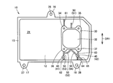
- FIG. 3 is a plan view of the converter case 10.
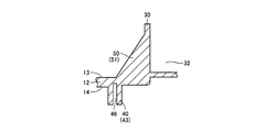
- FIG. 4 is an enlarged perspective view showing the vicinity of the rib 51 as the first rib.
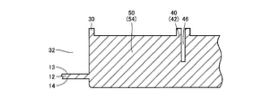
- FIG. 5 is a sectional view taken along the line VV shown in FIG.
- FIG. 6 is an enlarged perspective view showing the vicinity of ribs 52 to 54 as second ribs.
- FIG. 7 is a sectional view taken along line VII-VII shown in FIG. The configuration of the housing of the electric device will be described with reference to FIGS. 3 to 7 as appropriate.
- the converter case 10 is a housing that houses various electric devices that constitute the converter 710 shown in FIG.
- Converter case 10 has a base portion 12 on which an electric device is placed.
- the base portion 12 is formed in a flat plate shape, and has a front surface 13 and a back surface 14 opposite to the front surface 13.
- FIG. 3 shows the surface 13 side of the base portion 12.
- the electric equipment constituting the converter 710 is mounted on the surface 13 of the base portion 12.
- Converter case 10 includes a reactor case 30 surrounding reactor L shown in FIG. 2, and a board mounting portion 24 for mounting an electric board on which power transistors Q1, Q2 and diodes D1, D2 shown in FIG. 2 are mounted. Have.
- the converter case 10 has an outer wall portion 15 formed to protrude from the surface 13 along the peripheral edge portion.
- the schematic shape of the planar shape of the converter case 10 is a rectangular shape.
- a fastening portion 16 that protrudes outside the converter case 10 is provided on one side (the upper side in FIG. 3) of the long side of the rectangle.
- a pair of fastening portions 17 and 18 projecting outside the converter case 10 are provided on the other side (lower side in FIG. 3) of the long side of the rectangle.
- the fastening part 16 is formed with a through hole 26 that penetrates the fastening part 16 in the thickness direction.
- the fastening portion 17 is formed with a through hole 27 that penetrates the fastening portion 17 in the thickness direction.
- the fastening portion 18 is formed with a through hole 28 that penetrates the fastening portion 18 in the thickness direction.
- the base portion 12 of the converter case 10 has bosses 41 and 42 in which the base portion 12 protrudes toward the front surface 13 side and bosses 43 in which the base portion 12 protrudes toward the back surface 14 side at positions outside the reactor case 30. Is provided. In the bosses 41 to 43, a part of the base portion 12 is formed by increasing the dimension in the thickness direction. The bosses 41 to 43 are provided so that a part of the base portion 12 protrudes in the thickness direction of the base portion 12. On the plate-like base portion 12, bosses 41 to 43 projecting in the vertical direction are erected. The plurality of bosses 41 to 43 are integrally formed with the base portion 12.
- the bosses 41 and 42 protrude from the surface 13 of the base portion 12 for the purpose of fastening and fixing the bus bar.
- the boss 43 protrudes from the back surface 14 of the base portion 12 for the purpose of fastening and fixing the cooler.
- the bosses 41 to 43 are formed with fastening holes 46 as screw insertion holes.
- a female screw shape is formed on the inner surface of the fastening hole 46.
- the rib 50 includes a plurality of ribs 51-54.
- the rib 51 connects the surface 13 of the base portion 12 at the position where the boss 43 protrudes from the back surface 14 and the outer periphery of the reactor case 30.
- the ribs 52 and 53 connect the boss 41 and the outer periphery of the reactor case 30.
- the rib 54 connects the boss 42 and the outer periphery of the reactor case 30.
- the rib 50 can be formed to have a thickness of 2 mm, for example.
- rib 61 that connects the reactor case 30 and the outer wall portion 15 of the converter case 10
- rib 62 that connects the boss 41 and the outer wall portion 15, a reactor case 30 and a boss 42.
- ribs 64 and 65 for connecting the boss 42 and the outer wall portion 15 are provided upright.
- the outer peripheral surface of the reactor case 30 and the front surface 13 at a position where the boss 43 as the reinforcing portion 40 with the rigidity of the base portion 12 being increased is on the back surface 14 are connected by the rib 51.
- the outer peripheral surface of the reactor case 30 and the bosses 41 and 42 as the reinforcing portions 40 in which the rigidity of the base portion 12 is increased are connected by the ribs 52 to 54.
- the thick bosses 41 to 43 that are hard to vibrate and the reactor case 30 are connected by the ribs 51 to 54, so that the rigidity of the reactor case 30 surrounding the reactor L can be improved.
- the rigidity of the reactor case 30 is high, the vibration of the reactor case 30 when the vibration generated in the reactor L is transmitted to the reactor case 30 can be reduced.
- the vibration transmitted to the reactor case 30 is absorbed by the bosses 41 to 43, and the vibration is attenuated before being transmitted from the reactor case 30 to the converter case 10.
- Ribs 51 as first ribs are disposed on the outer peripheral portion of the upper reactor case 30 shown in FIG. 3, and ribs 52 to 54 as second ribs are provided on the outer peripheral portion of the lower reactor case 30 shown in FIG. Be placed.
- Ribs 50 are formed so as to extend from a portion of reactor case 30 facing each other in the vibration direction of reactor L to the outside of reactor case 30.
- the bosses 41 and 42 are arranged at positions away from the center of the reactor L in a direction orthogonal to the vibration direction of the reactor L.
- the bosses 41 and 42 are arranged away from each other on both sides of the position that bisects the reactor case 30 in the direction orthogonal to the vibration direction of the reactor L shown in FIG.
- FIG. 8 is a graph showing the vibration reduction effect by the ribs 51 to 54 of the present embodiment.
- the reactor vibration frequency of 9.55 kHz when the reactor was energized was simulated, the outer peripheral surface of the reactor case 30 on the side where the rib 51 was disposed was struck with a hammer (hammering), and the vibration at that time was measured.
- the measured values when there are no ribs 51 to 54 connected to the reactor case 30 and the measured values when there are ribs 51 to 54 are arranged side by side. This is illustrated in the graph.
- the white bar graph shown in FIG. 8 shows the case where the ribs 51 to 54 are not provided, and the hatched bar graph shown in FIG. 8 shows the case where the ribs 51 to 54 are provided.
- the vertical direction is the thickness direction of the base portion 12 (that is, the direction perpendicular to the paper surface in FIG. 3).
- the left-right direction is the left-right direction of the vehicle, and is a direction orthogonal to the vibration direction of the reactor L indicated by the double arrow DR1 in FIG. 3 (that is, the left-right direction in FIG. 3).
- the front-rear direction is the front-rear direction of the vehicle, and is the vibration direction of the reactor L indicated by the double arrow DR1 (that is, the up-down direction in FIG. 3).
- the vertical axis shown in FIG. 8 shows the transfer function (unit: dB) of vibration at each point obtained by placing an accelerometer at points A to D and measuring the acceleration at each point. .
- the configuration of the converter case 10 for reducing the vibration generated by the reactor L mounted on the hybrid vehicle has been described as an example.
- the scope of the present invention is not limited to this.
- the electric device applied to the present invention may be any device, and the electric device may be in-vehicle or not in-vehicle.
- the casing of the electric device of the present invention can be applied particularly advantageously to a casing that houses a reactor for boosting the voltage of a drive unit mounted on an electric vehicle.
Landscapes
- Engineering & Computer Science (AREA)
- Power Engineering (AREA)
- Microelectronics & Electronic Packaging (AREA)
- Electric Propulsion And Braking For Vehicles (AREA)
- Dc-Dc Converters (AREA)
- Casings For Electric Apparatus (AREA)
- Housings And Mounting Of Transformers (AREA)
Abstract
Priority Applications (5)
| Application Number | Priority Date | Filing Date | Title |
|---|---|---|---|
| PCT/JP2011/056384 WO2012124101A1 (fr) | 2011-03-17 | 2011-03-17 | Boîtier de dispositif électronique |
| US14/004,862 US9538674B2 (en) | 2011-03-17 | 2011-03-17 | Housing of electronic device |
| CN201180069345.7A CN103430257B (zh) | 2011-03-17 | 2011-03-17 | 电气设备的壳体 |
| EP11861254.8A EP2688077B1 (fr) | 2011-03-17 | 2011-03-17 | Boîtier de dispositif électronique |
| JP2013504478A JP5545411B2 (ja) | 2011-03-17 | 2011-03-17 | 電子機器の筐体 |
Applications Claiming Priority (1)
| Application Number | Priority Date | Filing Date | Title |
|---|---|---|---|
| PCT/JP2011/056384 WO2012124101A1 (fr) | 2011-03-17 | 2011-03-17 | Boîtier de dispositif électronique |
Publications (1)
| Publication Number | Publication Date |
|---|---|
| WO2012124101A1 true WO2012124101A1 (fr) | 2012-09-20 |
Family
ID=46830229
Family Applications (1)
| Application Number | Title | Priority Date | Filing Date |
|---|---|---|---|
| PCT/JP2011/056384 WO2012124101A1 (fr) | 2011-03-17 | 2011-03-17 | Boîtier de dispositif électronique |
Country Status (5)
| Country | Link |
|---|---|
| US (1) | US9538674B2 (fr) |
| EP (1) | EP2688077B1 (fr) |
| JP (1) | JP5545411B2 (fr) |
| CN (1) | CN103430257B (fr) |
| WO (1) | WO2012124101A1 (fr) |
Cited By (4)
| Publication number | Priority date | Publication date | Assignee | Title |
|---|---|---|---|---|
| JP2016092967A (ja) * | 2014-11-05 | 2016-05-23 | 株式会社ケーヒン | 電力変換装置 |
| CN114241729A (zh) * | 2021-12-13 | 2022-03-25 | 中国人民解放军陆军工程大学 | 一种振动冲击报警装置 |
| US11382581B2 (en) | 2018-09-28 | 2022-07-12 | Fujifilm Corporation | Radiation detection device |
| WO2022180872A1 (fr) * | 2021-02-25 | 2022-09-01 | 日本電産株式会社 | Module de moteur d'entraînement |
Families Citing this family (7)
| Publication number | Priority date | Publication date | Assignee | Title |
|---|---|---|---|---|
| DE102010041540A1 (de) * | 2010-09-28 | 2012-03-29 | Robert Bosch Gmbh | Steuergerät |
| JP5904235B2 (ja) * | 2014-05-30 | 2016-04-13 | トヨタ自動車株式会社 | 電動車両用の電力変換器 |
| US9283837B1 (en) * | 2015-01-28 | 2016-03-15 | Atieva, Inc. | Compliantly mounted motor assembly utilizing dual levels of vibration isolation |
| US9783063B2 (en) | 2015-08-27 | 2017-10-10 | Texas Instruments Incorporated | Regenerative braking controller for electric motors |
| KR102483532B1 (ko) * | 2015-10-20 | 2023-01-02 | 엘지이노텍 주식회사 | 전자부품 케이스 |
| JP6370285B2 (ja) * | 2015-10-28 | 2018-08-08 | 住友電装株式会社 | シールドカバー |
| US10252685B2 (en) | 2017-02-15 | 2019-04-09 | Ford Global Technologies, Llc | Optimized powertrain control module bracket |
Citations (7)
| Publication number | Priority date | Publication date | Assignee | Title |
|---|---|---|---|---|
| JPH01158024U (fr) | 1988-04-25 | 1989-10-31 | ||
| JPH0446635U (fr) | 1990-08-27 | 1992-04-21 | ||
| JP2006292312A (ja) | 2005-04-13 | 2006-10-26 | Daikin Ind Ltd | 高所設置型空気調和機の天板構造 |
| JP2007180140A (ja) * | 2005-12-27 | 2007-07-12 | Denso Corp | 磁気部品 |
| JP2007180145A (ja) * | 2005-12-27 | 2007-07-12 | Denso Corp | 磁気部品 |
| JP2008300786A (ja) | 2007-06-04 | 2008-12-11 | Tamura Seisakusho Co Ltd | リアクトル固定構造 |
| JP2009168344A (ja) | 2008-01-16 | 2009-07-30 | Daikin Ind Ltd | 空気調和装置の室内ユニット |
Family Cites Families (6)
| Publication number | Priority date | Publication date | Assignee | Title |
|---|---|---|---|---|
| DE2819716A1 (de) | 1978-05-05 | 1979-11-08 | Braun Ag | Gehaeuse fuer einen elektrischen rasierapparat |
| US4360838A (en) * | 1981-08-17 | 1982-11-23 | Zenith Radio Corporation | Means and method for mounting cathode ray picture tubes |
| KR100224305B1 (ko) * | 1996-12-05 | 1999-10-15 | 윤종용 | 브라운관과 프론트 케이스간의 사이뜸 방지구조를 가진 crt 화상표시장치 |
| US6067708A (en) * | 1997-12-15 | 2000-05-30 | Ford Global Technologies, Inc. | Method of interconnecting a dual media assembly |
| JP2010027692A (ja) * | 2008-07-15 | 2010-02-04 | Toyota Motor Corp | リアクトル |
| JP2010238874A (ja) * | 2009-03-31 | 2010-10-21 | Panasonic Corp | リアクタ |
-
2011
- 2011-03-17 WO PCT/JP2011/056384 patent/WO2012124101A1/fr active Application Filing
- 2011-03-17 US US14/004,862 patent/US9538674B2/en active Active
- 2011-03-17 CN CN201180069345.7A patent/CN103430257B/zh active Active
- 2011-03-17 JP JP2013504478A patent/JP5545411B2/ja active Active
- 2011-03-17 EP EP11861254.8A patent/EP2688077B1/fr active Active
Patent Citations (7)
| Publication number | Priority date | Publication date | Assignee | Title |
|---|---|---|---|---|
| JPH01158024U (fr) | 1988-04-25 | 1989-10-31 | ||
| JPH0446635U (fr) | 1990-08-27 | 1992-04-21 | ||
| JP2006292312A (ja) | 2005-04-13 | 2006-10-26 | Daikin Ind Ltd | 高所設置型空気調和機の天板構造 |
| JP2007180140A (ja) * | 2005-12-27 | 2007-07-12 | Denso Corp | 磁気部品 |
| JP2007180145A (ja) * | 2005-12-27 | 2007-07-12 | Denso Corp | 磁気部品 |
| JP2008300786A (ja) | 2007-06-04 | 2008-12-11 | Tamura Seisakusho Co Ltd | リアクトル固定構造 |
| JP2009168344A (ja) | 2008-01-16 | 2009-07-30 | Daikin Ind Ltd | 空気調和装置の室内ユニット |
Non-Patent Citations (1)
| Title |
|---|
| See also references of EP2688077A4 |
Cited By (4)
| Publication number | Priority date | Publication date | Assignee | Title |
|---|---|---|---|---|
| JP2016092967A (ja) * | 2014-11-05 | 2016-05-23 | 株式会社ケーヒン | 電力変換装置 |
| US11382581B2 (en) | 2018-09-28 | 2022-07-12 | Fujifilm Corporation | Radiation detection device |
| WO2022180872A1 (fr) * | 2021-02-25 | 2022-09-01 | 日本電産株式会社 | Module de moteur d'entraînement |
| CN114241729A (zh) * | 2021-12-13 | 2022-03-25 | 中国人民解放军陆军工程大学 | 一种振动冲击报警装置 |
Also Published As
| Publication number | Publication date |
|---|---|
| JPWO2012124101A1 (ja) | 2014-07-17 |
| EP2688077A1 (fr) | 2014-01-22 |
| EP2688077A4 (fr) | 2015-06-03 |
| US20140060918A1 (en) | 2014-03-06 |
| US9538674B2 (en) | 2017-01-03 |
| CN103430257B (zh) | 2016-03-16 |
| EP2688077B1 (fr) | 2016-11-09 |
| CN103430257A (zh) | 2013-12-04 |
| JP5545411B2 (ja) | 2014-07-09 |
Similar Documents
| Publication | Publication Date | Title |
|---|---|---|
| JP5545411B2 (ja) | 電子機器の筐体 | |
| JP5707279B2 (ja) | 電力変換装置 | |
| JP2007180225A (ja) | リアクトルの固定構造および電気機器ユニット | |
| JP2009026952A (ja) | リアクトルの固定構造 | |
| JP2007226996A (ja) | 電池パック構造 | |
| WO2014083964A1 (fr) | Dispositif d'onduleur, et dispositif d'onduleur intégré dans un moteur | |
| JP4840084B2 (ja) | 電圧変換装置およびこの電圧変換装置を備えた車両 | |
| JP2007223461A (ja) | 電気機器の搭載構造および電動車両 | |
| JP2014087124A (ja) | 電力変換装置 | |
| JP2009040263A (ja) | 車両搭載機器の固定構造 | |
| JP2009177000A (ja) | コンデンサ装置 | |
| JP5098840B2 (ja) | 車両搭載機器の固定構造 | |
| JP2009029275A (ja) | 車両搭載機器の固定構造 | |
| JP2005032830A (ja) | 制御装置およびそれを搭載した自動車 | |
| JP5082668B2 (ja) | 電気機器の固定構造 | |
| JP5932605B2 (ja) | 電力変換装置 | |
| JP4997056B2 (ja) | バスバー構造及びそれを用いた電力変換装置 | |
| JP7431529B2 (ja) | 車両の駆動装置 | |
| CN116762264A (zh) | 车用驱动装置 | |
| JP2009153264A (ja) | 電力制御ユニットの冷却構造 | |
| JP7151621B2 (ja) | 電力変換機 | |
| JP7431530B2 (ja) | 車両の駆動装置 | |
| JP2008159602A (ja) | 電圧変換装置およびこの電圧変換装置を備えた車両 | |
| WO2021157200A1 (fr) | Dispositif de conversion de puissance | |
| JP2009064802A (ja) | 電気機器の支持構造および車両 |
Legal Events
| Date | Code | Title | Description |
|---|---|---|---|
| WWE | Wipo information: entry into national phase |
Ref document number: 201180069345.7 Country of ref document: CN |
|
| 121 | Ep: the epo has been informed by wipo that ep was designated in this application |
Ref document number: 11861254 Country of ref document: EP Kind code of ref document: A1 |
|
| DPE2 | Request for preliminary examination filed before expiration of 19th month from priority date (pct application filed from 20040101) | ||
| ENP | Entry into the national phase |
Ref document number: 2013504478 Country of ref document: JP Kind code of ref document: A |
|
| WWE | Wipo information: entry into national phase |
Ref document number: 14004862 Country of ref document: US |
|
| NENP | Non-entry into the national phase |
Ref country code: DE |
|
| REEP | Request for entry into the european phase |
Ref document number: 2011861254 Country of ref document: EP |
|
| WWE | Wipo information: entry into national phase |
Ref document number: 2011861254 Country of ref document: EP |