WO2012124047A1 - 成膜装置 - Google Patents
成膜装置 Download PDFInfo
- Publication number
- WO2012124047A1 WO2012124047A1 PCT/JP2011/055986 JP2011055986W WO2012124047A1 WO 2012124047 A1 WO2012124047 A1 WO 2012124047A1 JP 2011055986 W JP2011055986 W JP 2011055986W WO 2012124047 A1 WO2012124047 A1 WO 2012124047A1
- Authority
- WO
- WIPO (PCT)
- Prior art keywords
- mist
- injection
- port
- nozzle
- forming apparatus
- Prior art date
- Legal status (The legal status is an assumption and is not a legal conclusion. Google has not performed a legal analysis and makes no representation as to the accuracy of the status listed.)
- Ceased
Links
Images








Classifications
-
- C—CHEMISTRY; METALLURGY
- C23—COATING METALLIC MATERIAL; COATING MATERIAL WITH METALLIC MATERIAL; CHEMICAL SURFACE TREATMENT; DIFFUSION TREATMENT OF METALLIC MATERIAL; COATING BY VACUUM EVAPORATION, BY SPUTTERING, BY ION IMPLANTATION OR BY CHEMICAL VAPOUR DEPOSITION, IN GENERAL; INHIBITING CORROSION OF METALLIC MATERIAL OR INCRUSTATION IN GENERAL
- C23C—COATING METALLIC MATERIAL; COATING MATERIAL WITH METALLIC MATERIAL; SURFACE TREATMENT OF METALLIC MATERIAL BY DIFFUSION INTO THE SURFACE, BY CHEMICAL CONVERSION OR SUBSTITUTION; COATING BY VACUUM EVAPORATION, BY SPUTTERING, BY ION IMPLANTATION OR BY CHEMICAL VAPOUR DEPOSITION, IN GENERAL
- C23C18/00—Chemical coating by decomposition of either liquid compounds or solutions of the coating forming compounds, without leaving reaction products of surface material in the coating; Contact plating
- C23C18/02—Chemical coating by decomposition of either liquid compounds or solutions of the coating forming compounds, without leaving reaction products of surface material in the coating; Contact plating by thermal decomposition
-
- B—PERFORMING OPERATIONS; TRANSPORTING
- B05—SPRAYING OR ATOMISING IN GENERAL; APPLYING FLUENT MATERIALS TO SURFACES, IN GENERAL
- B05B—SPRAYING APPARATUS; ATOMISING APPARATUS; NOZZLES
- B05B7/00—Spraying apparatus for discharge of liquids or other fluent materials from two or more sources, e.g. of liquid and air, of powder and gas
- B05B7/0012—Apparatus for achieving spraying before discharge from the apparatus
-
- H—ELECTRICITY
- H10—SEMICONDUCTOR DEVICES; ELECTRIC SOLID-STATE DEVICES NOT OTHERWISE PROVIDED FOR
- H10F—INORGANIC SEMICONDUCTOR DEVICES SENSITIVE TO INFRARED RADIATION, LIGHT, ELECTROMAGNETIC RADIATION OF SHORTER WAVELENGTH OR CORPUSCULAR RADIATION
- H10F71/00—Manufacture or treatment of devices covered by this subclass
- H10F71/137—Batch treatment of the devices
-
- B—PERFORMING OPERATIONS; TRANSPORTING
- B05—SPRAYING OR ATOMISING IN GENERAL; APPLYING FLUENT MATERIALS TO SURFACES, IN GENERAL
- B05B—SPRAYING APPARATUS; ATOMISING APPARATUS; NOZZLES
- B05B1/00—Nozzles, spray heads or other outlets, with or without auxiliary devices such as valves, heating means
- B05B1/02—Nozzles, spray heads or other outlets, with or without auxiliary devices such as valves, heating means designed to produce a jet, spray, or other discharge of particular shape or nature, e.g. in single drops, or having an outlet of particular shape
- B05B1/04—Nozzles, spray heads or other outlets, with or without auxiliary devices such as valves, heating means designed to produce a jet, spray, or other discharge of particular shape or nature, e.g. in single drops, or having an outlet of particular shape in flat form, e.g. fan-like, sheet-like
-
- B—PERFORMING OPERATIONS; TRANSPORTING
- B05—SPRAYING OR ATOMISING IN GENERAL; APPLYING FLUENT MATERIALS TO SURFACES, IN GENERAL
- B05B—SPRAYING APPARATUS; ATOMISING APPARATUS; NOZZLES
- B05B7/00—Spraying apparatus for discharge of liquids or other fluent materials from two or more sources, e.g. of liquid and air, of powder and gas
- B05B7/02—Spray pistols; Apparatus for discharge
- B05B7/04—Spray pistols; Apparatus for discharge with arrangements for mixing liquids or other fluent materials before discharge
- B05B7/0416—Spray pistols; Apparatus for discharge with arrangements for mixing liquids or other fluent materials before discharge with arrangements for mixing one gas and one liquid
-
- B—PERFORMING OPERATIONS; TRANSPORTING
- B05—SPRAYING OR ATOMISING IN GENERAL; APPLYING FLUENT MATERIALS TO SURFACES, IN GENERAL
- B05B—SPRAYING APPARATUS; ATOMISING APPARATUS; NOZZLES
- B05B7/00—Spraying apparatus for discharge of liquids or other fluent materials from two or more sources, e.g. of liquid and air, of powder and gas
- B05B7/02—Spray pistols; Apparatus for discharge
- B05B7/04—Spray pistols; Apparatus for discharge with arrangements for mixing liquids or other fluent materials before discharge
- B05B7/0416—Spray pistols; Apparatus for discharge with arrangements for mixing liquids or other fluent materials before discharge with arrangements for mixing one gas and one liquid
- B05B7/0441—Spray pistols; Apparatus for discharge with arrangements for mixing liquids or other fluent materials before discharge with arrangements for mixing one gas and one liquid with one inner conduit of liquid surrounded by an external conduit of gas upstream the mixing chamber
- B05B7/0458—Spray pistols; Apparatus for discharge with arrangements for mixing liquids or other fluent materials before discharge with arrangements for mixing one gas and one liquid with one inner conduit of liquid surrounded by an external conduit of gas upstream the mixing chamber the gas and liquid flows being perpendicular just upstream the mixing chamber
-
- C—CHEMISTRY; METALLURGY
- C23—COATING METALLIC MATERIAL; COATING MATERIAL WITH METALLIC MATERIAL; CHEMICAL SURFACE TREATMENT; DIFFUSION TREATMENT OF METALLIC MATERIAL; COATING BY VACUUM EVAPORATION, BY SPUTTERING, BY ION IMPLANTATION OR BY CHEMICAL VAPOUR DEPOSITION, IN GENERAL; INHIBITING CORROSION OF METALLIC MATERIAL OR INCRUSTATION IN GENERAL
- C23C—COATING METALLIC MATERIAL; COATING MATERIAL WITH METALLIC MATERIAL; SURFACE TREATMENT OF METALLIC MATERIAL BY DIFFUSION INTO THE SURFACE, BY CHEMICAL CONVERSION OR SUBSTITUTION; COATING BY VACUUM EVAPORATION, BY SPUTTERING, BY ION IMPLANTATION OR BY CHEMICAL VAPOUR DEPOSITION, IN GENERAL
- C23C16/00—Chemical coating by decomposition of gaseous compounds, without leaving reaction products of surface material in the coating, i.e. chemical vapour deposition [CVD] processes
- C23C16/44—Chemical coating by decomposition of gaseous compounds, without leaving reaction products of surface material in the coating, i.e. chemical vapour deposition [CVD] processes characterised by the method of coating
- C23C16/448—Chemical coating by decomposition of gaseous compounds, without leaving reaction products of surface material in the coating, i.e. chemical vapour deposition [CVD] processes characterised by the method of coating characterised by the method used for generating reactive gas streams, e.g. by evaporation or sublimation of precursor materials
- C23C16/4486—Chemical coating by decomposition of gaseous compounds, without leaving reaction products of surface material in the coating, i.e. chemical vapour deposition [CVD] processes characterised by the method of coating characterised by the method used for generating reactive gas streams, e.g. by evaporation or sublimation of precursor materials by producing an aerosol and subsequent evaporation of the droplets or particles
-
- C—CHEMISTRY; METALLURGY
- C23—COATING METALLIC MATERIAL; COATING MATERIAL WITH METALLIC MATERIAL; CHEMICAL SURFACE TREATMENT; DIFFUSION TREATMENT OF METALLIC MATERIAL; COATING BY VACUUM EVAPORATION, BY SPUTTERING, BY ION IMPLANTATION OR BY CHEMICAL VAPOUR DEPOSITION, IN GENERAL; INHIBITING CORROSION OF METALLIC MATERIAL OR INCRUSTATION IN GENERAL
- C23C—COATING METALLIC MATERIAL; COATING MATERIAL WITH METALLIC MATERIAL; SURFACE TREATMENT OF METALLIC MATERIAL BY DIFFUSION INTO THE SURFACE, BY CHEMICAL CONVERSION OR SUBSTITUTION; COATING BY VACUUM EVAPORATION, BY SPUTTERING, BY ION IMPLANTATION OR BY CHEMICAL VAPOUR DEPOSITION, IN GENERAL
- C23C16/00—Chemical coating by decomposition of gaseous compounds, without leaving reaction products of surface material in the coating, i.e. chemical vapour deposition [CVD] processes
- C23C16/44—Chemical coating by decomposition of gaseous compounds, without leaving reaction products of surface material in the coating, i.e. chemical vapour deposition [CVD] processes characterised by the method of coating
- C23C16/455—Chemical coating by decomposition of gaseous compounds, without leaving reaction products of surface material in the coating, i.e. chemical vapour deposition [CVD] processes characterised by the method of coating characterised by the method used for introducing gases into reaction chamber or for modifying gas flows in reaction chamber
-
- C—CHEMISTRY; METALLURGY
- C23—COATING METALLIC MATERIAL; COATING MATERIAL WITH METALLIC MATERIAL; CHEMICAL SURFACE TREATMENT; DIFFUSION TREATMENT OF METALLIC MATERIAL; COATING BY VACUUM EVAPORATION, BY SPUTTERING, BY ION IMPLANTATION OR BY CHEMICAL VAPOUR DEPOSITION, IN GENERAL; INHIBITING CORROSION OF METALLIC MATERIAL OR INCRUSTATION IN GENERAL
- C23C—COATING METALLIC MATERIAL; COATING MATERIAL WITH METALLIC MATERIAL; SURFACE TREATMENT OF METALLIC MATERIAL BY DIFFUSION INTO THE SURFACE, BY CHEMICAL CONVERSION OR SUBSTITUTION; COATING BY VACUUM EVAPORATION, BY SPUTTERING, BY ION IMPLANTATION OR BY CHEMICAL VAPOUR DEPOSITION, IN GENERAL
- C23C16/00—Chemical coating by decomposition of gaseous compounds, without leaving reaction products of surface material in the coating, i.e. chemical vapour deposition [CVD] processes
- C23C16/44—Chemical coating by decomposition of gaseous compounds, without leaving reaction products of surface material in the coating, i.e. chemical vapour deposition [CVD] processes characterised by the method of coating
- C23C16/455—Chemical coating by decomposition of gaseous compounds, without leaving reaction products of surface material in the coating, i.e. chemical vapour deposition [CVD] processes characterised by the method of coating characterised by the method used for introducing gases into reaction chamber or for modifying gas flows in reaction chamber
- C23C16/45514—Mixing in close vicinity to the substrate
-
- C—CHEMISTRY; METALLURGY
- C23—COATING METALLIC MATERIAL; COATING MATERIAL WITH METALLIC MATERIAL; CHEMICAL SURFACE TREATMENT; DIFFUSION TREATMENT OF METALLIC MATERIAL; COATING BY VACUUM EVAPORATION, BY SPUTTERING, BY ION IMPLANTATION OR BY CHEMICAL VAPOUR DEPOSITION, IN GENERAL; INHIBITING CORROSION OF METALLIC MATERIAL OR INCRUSTATION IN GENERAL
- C23C—COATING METALLIC MATERIAL; COATING MATERIAL WITH METALLIC MATERIAL; SURFACE TREATMENT OF METALLIC MATERIAL BY DIFFUSION INTO THE SURFACE, BY CHEMICAL CONVERSION OR SUBSTITUTION; COATING BY VACUUM EVAPORATION, BY SPUTTERING, BY ION IMPLANTATION OR BY CHEMICAL VAPOUR DEPOSITION, IN GENERAL
- C23C16/00—Chemical coating by decomposition of gaseous compounds, without leaving reaction products of surface material in the coating, i.e. chemical vapour deposition [CVD] processes
- C23C16/44—Chemical coating by decomposition of gaseous compounds, without leaving reaction products of surface material in the coating, i.e. chemical vapour deposition [CVD] processes characterised by the method of coating
- C23C16/455—Chemical coating by decomposition of gaseous compounds, without leaving reaction products of surface material in the coating, i.e. chemical vapour deposition [CVD] processes characterised by the method of coating characterised by the method used for introducing gases into reaction chamber or for modifying gas flows in reaction chamber
- C23C16/45595—Atmospheric CVD gas inlets with no enclosed reaction chamber
Definitions
- the present invention relates to a film forming apparatus for forming a thin film, and particularly relates to a film forming apparatus capable of forming a thin film on a substrate by spraying mist onto the substrate.
- a step of forming a thin film on a substrate is executed.
- a thin film is formed on a substrate by spraying a raw material mist on the substrate (see Patent Document 1).
- a raw material mist injected from an ejection nozzle is sprayed on a substrate, and a thin film is formed on the substrate.
- the ejection nozzle includes a large-volume gas reservoir, an ejection section having an ejection port having a flat cross-sectional shape, and a mist supply pipe.
- the ejection nozzle is installed so that the ejection direction of the raw material mist is perpendicular to the direction parallel to the plane of the substrate.
- the raw material mist is supplied from a mist supply port provided in the gas reservoir, and the raw material mist is ejected from an injection port having a smaller cross-sectional area than the supply port, thereby making the raw material mist uniform. ing.
- the technique according to Patent Document 1 requires a mist supply port having a large cross-sectional area in order to enable uniform injection of the raw material mist.
- the opening area of the injection port is determined to be a predetermined size, and the area of the mist supply port needs to be sufficiently larger than the opening area of the injection port.
- the mist is applied to an injection port having a flat cross-sectional shape. It is necessary to provide a large number of thick pipes for supply in the gas reservoir.
- the technique according to Patent Document 1 has a problem that the structure around the ejection nozzle is enlarged. That is, in the technique according to Patent Document 1, there is a limitation that the total opening area of the mist supply port must be sufficiently increased according to the opening area of the injection port, and it is difficult to simplify the configuration of the ejection nozzle. It was. Further, due to the enlargement of the configuration, the maintainability around the ejection nozzle is deteriorated, the assembly of the ejection nozzle is complicated, and the manufacturing cost is further increased.
- the present invention provides a film forming apparatus capable of preventing the enlargement of the configuration around the nozzle for mist injection while maintaining uniform mist ejection to the substrate on which film formation is performed. Objective.
- a film forming apparatus performs film formation using a mist generator that generates mist as a film forming raw material, and the mist generated by the mist generator.
- a mist injection nozzle that injects into the substrate, and the mist injection nozzle is formed in the body portion having a hollow portion, and the mist generated by the mist generator is formed in the body portion.
- a mist supply port that supplies the mist to the inside of the hollow portion, a first injection port that is formed in the main body portion and injects the mist of the hollow portion to the outside, and is formed outside the main portion, and the mist is injected into the first portion.
- At least one carrier gas supply port for supplying a carrier gas to the mouth into the hollow portion, and a shower plate disposed in the hollow portion and formed with a plurality of holes.
- Department The shower plate is divided into a first space connected to the carrier gas supply port and a second space connected to the first injection port, and the mist supply port is The main body is formed so as to be connected to the second space.
- a film forming apparatus is a mist generator that generates a mist that is a raw material for film formation, and for mist injection that injects the mist generated by the mist generator onto a substrate on which a film is formed.
- a nozzle, and the mist injection nozzle includes a main body having a hollow portion, a mist supply port formed in the main body and supplying the mist generated by the mist generator into the hollow portion.
- a first injection port that is formed in the main body portion and injects the mist of the hollow portion to the outside, and a carrier gas that is formed outside the main portion and carries the mist to the first injection port is hollow.
- At least one carrier gas supply port that is supplied into the part, and a shower plate that is arranged in the hollow part and has a plurality of holes, and the hollow part is provided with the shower plate.
- a first space connected to the carrier gas supply port and a second space connected to the first injection port, and the mist supply port is connected to the second space.
- the carrier gas supplied and diffused in the first space is made uniform by passing through the shower plate and flows into the second space.
- the mist supplied and staying in the second space is rectified and uniformed by the carrier gas, propagated (pushed away) to the first injection port, and the uniformed mist together with the carrier gas. , And can be ejected from the first ejection port toward the substrate.
- a uniform mist on the substrate a desired thin film can be uniformly formed on the upper surface of the substrate.
- the shower plate due to the presence of the shower plate, uniform mist can be injected from the first injection port without increasing the opening area or number of the mist supply ports. Therefore, the opening area and number of the mist supply ports can be reduced, and the enlargement of the configuration around the mist injection nozzle can be prevented. Therefore, the maintainability around the mist ejection nozzle is improved, the assembly of the mist ejection nozzle is simplified, and the manufacturing cost can be reduced.
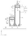
- FIG. 1 is a cross-sectional view illustrating a configuration of a film forming apparatus according to Embodiment 1.
- FIG. 3 is a plan view showing a configuration of a shower plate 7.
- 3 is a cross-sectional view illustrating a nozzle configuration that is a comparison target of the mist injection nozzle 1 according to Embodiment 1.
- FIG. 6 is a cross-sectional view illustrating a configuration of a film forming apparatus according to a third embodiment. 6 is a perspective view showing an outline of an external configuration of a mist injection nozzle 1 according to Embodiment 3.
- FIG. 1 is a cross-sectional view illustrating a configuration of a film forming apparatus according to Embodiment 1.
- FIG. 3 is a plan view showing a configuration of a shower plate 7.
- 3 is a cross-sectional view illustrating a nozzle configuration that is a comparison target of the mist injection nozzle 1 according to Embodiment 1.
- FIG. FIG. 6 is a cross-section
- FIG. 6 is a cross-sectional view showing a configuration of a film forming apparatus according to Embodiment 4.
- FIG. 10 is a cross-sectional view showing another configuration example of the film forming apparatus according to Embodiment 4.
- FIG. 10 is a cross-sectional view showing another configuration example of the film forming apparatus according to Embodiment 4.
- FIG. 10 is a cross-sectional view showing another configuration example of the film forming apparatus according to Embodiment 4.
- FIG. FIG. 6 is a cross-sectional view showing a configuration of a film forming apparatus according to a fifth embodiment. 6 is a plan view showing a schematic configuration of a film forming apparatus according to Embodiment 5.
- FIG. 10 is a cross-sectional view showing a configuration of a film forming apparatus according to a sixth embodiment.
- 7 is a plan view showing a schematic configuration of a film forming apparatus according to Embodiment 6.
- FIG. 10 is a cross-sectional view illustrating a configuration of a film forming apparatus according to a seventh embodiment.
- the present invention relates to a film forming apparatus used when forming a thin film on a substrate.
- the film forming apparatus according to the present invention has a mist injection nozzle for injecting a thin film raw material mist to the substrate, and forms a thin film on the substrate by the mist injection.
- a thin film is not formed on the substrate by exposing the vaporized gas to the substrate, but a liquid “mist” is sprayed on the substrate to A thin film is formed.
- the liquid “mist” means a droplet having a particle size of 100 ⁇ m or less.
- the lower limit of the particle size of the “mist” is not particularly limited as long as it is not gas but liquid. However, for example, the lower limit of the “mist” is about 0.1 ⁇ m.
- FIG. 1 is a perspective view showing an external configuration of a mist injection nozzle 1 provided in the film forming apparatus according to the present embodiment.
- FIG. 1 coordinate axes XYZ are also shown.
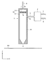
- FIG. 2 is a cross-sectional view showing a schematic configuration of the entire film forming apparatus.
- FIG. 2 is a cross-sectional view of the configuration of FIG. 1 when viewed from the Y direction.
- the mist generator 2 various pipes 3, 4, 5, 6, the mist supply port 5a, the carrier gas supply port 6a, and the first injection port shown in FIG. Illustration of 8 is omitted.
- FIG. 2 the XZ coordinate system is also shown.
- the mist injection nozzle 1 is positioned above the substrate 100 in order to form a thin film on the rectangular substrate 100 having a side of 1 m or more.
- the mist injection nozzle 1 injects mist, which is a film forming raw material, onto the upper surface of the substrate 100.
- the substrate 100 is moved in the horizontal direction while performing the injection.
- the mist injection accompanying the movement the mist can be sprayed over the entire upper surface of the substrate 100, and as a result, a uniform thin film can be formed over the entire upper surface of the substrate 100.
- the substrate 100 is heated to the film forming temperature. Further, the distance between the upper surface of the substrate 100 and the end of the mist injection nozzle 1 in the mist injection is, for example, about several tens of mm or less.
- the film forming apparatus includes a mist injection nozzle 1 and a mist generator 2.
- the nozzle 1 for mist injection is comprised by the main-body part 1A which has the hollow part 1H.
- the main body 1A has a short width in the X direction (for example, about several centimeters) and a long depth in the Y direction (slightly longer than the dimension of the substrate 100 in the Y direction). 1 m or more), and the height in the Z direction is slightly higher (for example, about 10 to 20 cm), and has a substantially rectangular parallelepiped outline appearance.
- the main body 1A may be made of stainless steel, for example, but may be made of aluminum from the viewpoint of weight reduction. In the case of aluminum, it is desirable to perform coating in order to improve the corrosion resistance of the main body 1A.
- a mist supply port 5a, a carrier gas supply port 6a, and an injection port (which can be grasped as a first injection port) 8 are formed in the main body 1A.
- the mist supply port 5a is provided on the side wall of the main body 1A, and serves as a mist inlet for supplying the mist generated by the mist generator 2 into the hollow portion 1H of the main body 1A. As shown in FIG. 2, in the present embodiment, the mist generated by the mist generator 2 reaches the mist supply port 5a through the mist pipe 5, and enters the inside of the main body 1A from the mist supply port 5a. Supplied.
- the number of the mist supply ports 5a may be one, or two or more mist supply ports 5a may be provided along the Y direction on the side wall of the main body 1A, but the configuration of the mist injection nozzle 1 is simplified. From the viewpoint of making it easier, the number of mist supply ports 5a is preferably smaller. Further, according to the number of mist supply ports 5a, naturally, mist pipes 5 for connecting the mist supply ports 5a and the mist generator 2 are respectively provided.
- the opening area of the mist supply port 5a and the opening area of the mist pipe 5 are too small, the mist may be clogged. Therefore, the opening area of the mist supply port 5a and the opening area of the mist pipe 5 need only be large enough to prevent the clogging.
- the ejection port 8 serves as a mist outlet that ejects the mist inside the main body 1 ⁇ / b> A toward the substrate 100. Therefore, the injection port 8 is formed on the surface of the main body portion 1A facing the upper surface (thin film formation surface) of the substrate 100 during mist injection. That is, the injection port 8 is formed on the lower surface side of the main body 1A.
- the width of the injection port 8 in the X direction is narrower than the width of the hollow portion 1H of the main body 1A in the X direction. For example, the width of the injection port 8 in the X direction is about 1 to 2 mm.
- the opening shape of the injection port 8 is a slit shape, and the dimension of the Y direction of the injection port 8 is a little smaller than the dimension of the Y direction of the main-body part 1A. And the thin main-body part 1A exists in the both ends of the injection port 8 in a Y direction.
- the carrier gas supply port 6a is provided on a surface (that is, the upper surface side of the main body 1A) facing the injection port 8 of the main body 1A (as will be described later, the carrier gas If the gas supply port 6a is connected to the first space 1S, the carrier gas supply port 6a may be disposed on the side surface of the main body 1A).
- the carrier gas supply port 6a serves as a carrier gas inlet for supplying the carrier gas from the outside of the mist injection nozzle 1 into the hollow portion 1H of the main body 1A. As shown in FIG. 2, the carrier gas reaches the carrier gas supply port 6a through the carrier gas pipe 6, and is supplied into the main body 1A from the carrier gas supply port 6a.
- the carrier gas is a gas for transporting the mist staying in the hollow portion 1H of the main body 1A to the ejection port 8 and ejecting it from the ejection port 8.
- the carrier gas for example, air, nitrogen, inert gas, or the like can be used.
- the number of carrier gas supply ports 6a may be one, or two or more may be provided in the main body portion 1A. From the viewpoint of simplifying the configuration of the mist injection nozzle 1, The number of gas supply ports 6a is preferably small. In addition, naturally, carrier gas pipes 6 connected to the respective carrier gas supply ports 6a are arranged in accordance with the number of carrier gas supply ports 6a.
- the opening area of the carrier gas supply port 6a and the opening area of the carrier gas pipe 6 are too large, the configuration is enlarged. Therefore, it is preferable that the opening area of the carrier gas supply port 6a and the opening area of the carrier gas pipe 6 are as small as possible so as to satisfy the relationship described later with the opening area of the hole 7a formed in the shower plate 7.
- a shower plate 7 is disposed on the mist injection nozzle 1. As shown in FIGS. 1 and 2, the shower plate 7 is disposed in the hollow portion 1H of the main body 1A. As can be seen from FIG. 2, the hollow portion 1H is divided into two spaces 1S and 1T by the shower plate 7. That is, in the hollow portion 1H, the shower plate 7 partitions the first space 1S and the second space 1T.
- FIG. 3 is a plan view of the shower plate 7 along the XY plane.
- the shower plate 7 is a thin plate and can be made of stainless steel, for example.
- the shower plate 7 is provided with a plurality of holes 7 a that are equally (unlike FIG. 3, they may not be equal).
- the opening shape of each hole 7 a is a round shape, and the holes 7 a are arranged alternately. Further, each hole 7 a penetrates in the thickness direction of the shower plate 7. Note that a carrier gas which is a “gas” passes through the hole 7a. Therefore, the opening diameter of each 7a can be made minute.
- the opening diameter of each hole 7a is not limited, it is about 0.01 mm as an example.
- the carrier gas supply port 6a is connected to the first space 1S, and the injection port 8 and the mist supply port 5a are connected to the second space 1T.
- the carrier gas supplied from the carrier gas supply port 6a diffuses and fills the first space 1S due to the presence of the shower plate 7, and is uniformly guided to the second space 1T through the holes 7a.
- the mist supplied from the mist supply port 5a and filled in the second space 1T is guided to the injection port 8 along with the flow of the carrier gas, and is uniformly injected from the injection port 8.
- a raw material solution in which a raw material of a thin film to be formed is dissolved is supplied through a raw material solution pipe 4.
- the supplied raw material solution is made into a mist form (atomization).
- the mist generator 2 supplies the mist that is the atomized raw material into the mist injection nozzle 1 through the mist pipe 5.
- air, nitrogen, an inert gas, or the like can be employed as the carrier gas.
- the shower plate 7 having a large number of holes 7a is disposed in the hollow portion 1H, and the carrier gas is more than the shower plate 7.
- a mist supply port 5 a is formed on the downstream side of the nozzle and upstream of the carrier gas from the injection port 8.
- the carrier gas supplied and diffused in the first space 1S is made uniform by passing through the shower plate 7, and flows into the second space 1T. Then, the mist supplied and staying in the second space 1T is rectified and uniformed by the carrier gas, propagated (spread) to the injection port 8, and the uniformed mist together with the carrier gas It can be ejected from the ejection port 8 toward the substrate 100.
- a desired thin film can be uniformly formed on the upper surface of the substrate 100.
- the presence of the shower plate 7 makes it possible to perform injection without increasing the opening area and number of the mist pipes 5 and the opening area and number of the mist supply ports 5a as in the technique according to Patent Document 1.
- a uniform mist can be injected from the mouth 8. Therefore, the opening area and number of the mist pipes 5 and the opening area and number of the mist supply ports 5a can be reduced, and the enlargement of the configuration around the mist injection nozzle 1 can be prevented. Therefore, maintainability around the mist ejection nozzle 1 is improved, the assembly of the mist ejection nozzle 1 is simplified, and the manufacturing cost can be reduced.
- the carrier gas diffused into the first space 1S can be reduced even if the opening area and number of the carrier gas pipe 6 and the opening area and number of the carrier gas supply port 6a are reduced due to the presence of the shower plate 7. It becomes possible to feed the second space 1T in a uniform state.
- the mist supply port 5a in the main body 1A on the downstream side of the carrier gas from the shower plate 7 (that is, so as to be connected to the second space 1T), It is possible to prevent clogging due to mist from occurring in the hole 7a formed in the shower plate 7.
- the carrier gas flows through the hole 7 a formed in the shower plate 7.
- the carrier gas is “gas”, the hole 7a is not clogged by the carrier gas.
- the sum of the opening areas of the plurality of holes 7a formed in the shower plate 7 is smaller than the opening area of the carrier gas supply port 6a.
- the total opening area of the holes 7a is smaller than the total opening area of the carrier gas supply ports 6a.
- a carrier gas having a uniform flow rate can be sent out from the hole 7a of the shower plate 7 into the second space 1T while diffusing the carrier gas in the first space 1S.
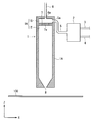
- FIG. 5 shows the configuration of the film forming apparatus according to this embodiment.
- the mist pipe 5 is omitted, and the mist generator 2 is directly connected to the mist injection nozzle 1.
- a rectangular mist supply port 5a is formed in the side surface of the main body 1A.
- the mist generator 2 is connected to the side surface of the main-body part 1A directly so that the said mist supply port 5a may be plugged up.
- 1 A of main-body parts and the mist generator 2 are directly connected using fastening means, such as a volt
- the structure other than the above is the same as the film forming apparatus according to the first embodiment and the film forming apparatus according to the present embodiment.
- the raw material solution misted by the mist generator 2 is directly propagated to the carrier gas and supplied into the mist injection nozzle 1 without passing through the mist pipe.
- mist pipe 5 shown in FIG. 2 can be omitted, the configuration of the film forming apparatus can be further simplified, the manufacturing cost of the film forming apparatus can be further reduced, and the film forming apparatus can be assembled. It becomes simple.
- the mist generated by the mist generator 2 is squeezed by the mist pipe 5 and supplied to the second space 1T.
- the mist is squeezed.
- the mist generated by the mist generator 2 can be sent into the second space 1T. Therefore, compared with the configuration according to the first embodiment, the configuration according to the present embodiment can further improve the supply efficiency of mist. Further, due to the omission of the mist pipe 5, in the film forming apparatus according to the present embodiment, the occurrence of mist condensation or the like in the mist pipe 5 is naturally eliminated.
- a rectangular (long in the Y direction) mist supply port 5a is formed in the main body 1A, so that a wide range in the second space 1T can be provided without arranging a plurality of mist pipes. Mist can be supplied.
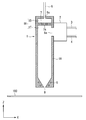
- FIG. 7 shows the configuration of the film forming apparatus according to this embodiment.
- a temperature adjustment unit is provided in the main body 1A.
- the configuration except that the temperature adjusting unit 9 is provided is the same as the film forming apparatus according to the other embodiment and the film forming apparatus according to the present embodiment.
- the temperature adjustment unit 9 is formed in the main body 1 ⁇ / b> A around the injection port 8.
- a flow path can be adopted.
- the temperature adjustment is performed by heating or cooling in a temperature range in which the mist does not aggregate in the hollow portion 1H and the mist does not react, decompose, or form a film in the hollow portion 1H.
- the temperature adjusted by the temperature adjusting unit 9 varies depending on the heating temperature of the substrate 100 and the type of the raw material of the thin film that is a component of the mist.
- the mist may agglomerate when it contacts the inner wall of the mist injection nozzle 1 having a low temperature.
- the aggregation of the mist prevents uniform injection of the mist or causes the mist aggregation liquid to fall on the substrate 100. Further, when the mist in the mist injection nozzle 1 is aggregated, the use efficiency of the raw material for the thin film is lowered.
- mist injection nozzle 1 when the mist injection nozzle 1 becomes too hot, the mist raw material decomposes and forms a film in the mist injection nozzle 1 or the mist solvent evaporates and the raw material precipitates even if it does not decompose. Even in this phenomenon, the uniform injection of mist is hindered and the use efficiency of the raw material for the thin film is reduced.
- the mist injection nozzle 1 includes a temperature adjustment unit 9. Accordingly, the mist can be kept at an appropriate temperature in the mist injection nozzle 1 so that the mist does not aggregate and the mist does not vaporize or decompose.
- FIG. 7 is a configuration in which the temperature adjustment unit 9 is added to the configuration in FIG. 5, the configuration in which the temperature adjustment unit 9 is added in the same manner as described above in the configuration illustrated in FIG. It can be employed (see FIG. 8).
- the temperature adjusting unit 9 is formed in the main body 1 ⁇ / b> A around the injection port 8. Although the substrate 100 is heated, the vicinity of the injection port 8 of the main body 1A is most affected by the heating. Therefore, at least the temperature adjusting unit 9 is provided in the main body 1A around the injection port 8 to prevent the structure (or enlargement) of the structure of the main body 1A, and the temperature inside the hollow portion 1H (in particular, the injection port). The temperature in the vicinity of 8) can be adjusted to an appropriate temperature (temperature range in which mist aggregation, mist decomposition / precipitation does not occur).
- the temperature adjusting portion 9 is uniformly disposed on the entire wall portion of the main body portion 1A (or at least the entire wall portion of the main body portion 1A facing the second space 1T). May be.
- the entire temperature in the hollow portion 1H (or the second space 1T) can be adjusted to a more appropriate temperature than the configuration shown in FIGS. That is, in the configuration shown in FIGS. 9 and 10, it is possible to completely prevent reduction of mist aggregation, decomposition, precipitation, and the like in the hollow portion 1H.
- the flow path through which the temperature-adjusted fluid can flow is listed as an example of the temperature adjustment unit 9, but other configurations (for example, heat can be used as long as the temperature adjustment in the hollow portion 1 H is possible. Pipes, cool plates, hot plates, etc.) can also be used.
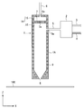
- FIG. 11 shows the configuration of the film forming apparatus according to this embodiment.
- a plan view of the configuration of FIG. 11 viewed from the Z direction is shown in FIG.
- the illustration of the mist generator 2 and the various pipes 3, 4, 6, and 11 is omitted from the viewpoint of simplifying the drawing.
- the film forming apparatus includes a reaction promoting gas injection nozzle 10 in addition to the mist injection nozzle 1.
- the nozzle shown in FIG. 7 is illustrated as the mist injection nozzle 1. Since the configuration of the mist injection nozzle 1 has been described in each of the above embodiments, the description thereof is omitted here.
- the reaction promoting gas injection nozzle 10 when forming a thin film on the substrate 100, the reaction promoting gas injection nozzle 10 is disposed above the substrate 100 in the same manner as the mist injection nozzle 1.
- the mist injection nozzle 1 injects mist onto the upper surface of the substrate 100
- the reaction promoting gas injection nozzle 10 injects reaction promoting gas onto the upper surface of the substrate 100.
- the reaction promoting gas is a gas that promotes the decomposition reaction of the mist containing the film forming raw material, and an active gas can be adopted.
- Specific examples of the reaction promoting gas include ozone, ammonia, hydrogen peroxide, and the like.
- the substrate 100 is moved in the horizontal direction (X direction in FIG. 12) while spraying the mist and the reaction promoting gas.
- the reaction promoting gas injection port (which can be grasped as the second injection port) 13 allows the injected mist and the injected reaction promoting gas to be mixed in the vicinity of the upper surface of the substrate 100. Adjacent to the injection port 8.
- the injection port 8 and the injection port 13 are adjacent to each other within a distance of about several millimeters. Further, it is desirable that the injection port 8 and / or the injection port 13 have a shape in which the injection direction of the mist and the injection direction of the reaction promoting gas intersect in the vicinity of the upper surface of the substrate 100.
- both the distance from the upper surface of the substrate 100 to the injection port 8 and the distance from the upper surface of the substrate 100 to the injection port 13 are preferably the same, and the distance is several mm (for example, about 1 to 2 mm).
- the mist injection force (mist injection flow rate) and the reaction promoting gas injection force (reaction promoting gas injection flow rate) are, for example, the same (note that the mist injection force (mist injection flow rate) and the reaction acceleration). It may be different from the gas injection force (injection flow rate of the reaction promoting gas).
- the reaction promoting gas injection nozzle 10 is constituted by a main body portion 10A having a hollow portion 10H.
- the main body 10A has a short width in the X direction (for example, about several centimeters) and a long depth in the Y direction (same as the dimensions of the mist injection nozzle 1 in the Y direction,
- the height in the Z direction is not particularly limited, but the configuration example of FIG. 11 has a substantially rectangular parallelepiped outline appearance that is lower than the height in the Z-axis direction of the mist injection nozzle 1.
- the injection port 13 and the reaction promoting gas supply port 11a are formed in the main body 10A.
- the injection port 13 serves as an outlet for the reaction promoting gas for injecting the reaction promoting gas inside the main body 10 ⁇ / b> A toward the substrate 100. Accordingly, the injection port 13 is formed on the surface of the main body 10A facing the upper surface (thin film formation surface) of the substrate 100 during the reaction promoting gas injection. That is, the injection port 13 is formed on the lower surface side of the main body 10A.
- the width of the injection port 13 in the X direction is narrower than the width of the hollow portion 10H of the main body 10A in the X direction. For example, the width of the injection port 13 in the X direction is about 1 to 2 mm.
- the opening shape of the injection port 13 is a slit shape, and the dimension of the Y direction of the injection port 13 is the same as the dimension of the Y direction of the injection port 8.
- the thin main-body part 10A exists in the both ends of the injection port 13 in a Y direction.
- the reaction promoting gas supply port 11a is provided on a surface (that is, the upper surface side of the main body 10A) facing the injection port 13 of the main body 10A (in addition, the reaction promoting gas supply).
- the mouth 11a may be disposed on the side surface of the main body 10A).
- the reaction promoting gas supply port 11a serves as an inlet for the reaction promoting gas for supplying the reaction promoting gas from the outside of the reaction promoting gas injection nozzle 10 into the hollow portion 10H of the main body 10A.
- the reaction promoting gas passes through the reaction promoting gas pipe 11, reaches the reaction promoting gas supply port 11a, and is supplied from the reaction promoting gas supply port 11a to the inside of the main body 10A.
- the number of the reaction promoting gas supply ports 11a may be one, or two or more may be provided along the Y direction on the upper surface of the main body 10A. From the viewpoint of simplifying the configuration of 10, it is preferable that the number of the reaction promoting gas supply ports 11a is small. Further, naturally, reaction promotion gas pipes 11 connected to the respective reaction promotion gas supply ports 11a are provided in accordance with the number of reaction promotion gas supply ports 11a.
- the opening area of the reaction promoting gas supply port 11a and the opening area of the reaction promoting gas pipe 11 are too large, the configuration is enlarged. Therefore, it is desirable that the total opening area of the reaction promoting gas supply port 11a is larger than the total opening area of the holes 71a formed in the shower plate 71, and the opening of the reaction promoting gas supply port 11a is within a range satisfying this relationship.
- the area is preferably as small as possible.
- a shower plate 71 is disposed in the reaction promoting gas injection nozzle 10. As shown in FIG. 11, the shower plate 71 is disposed in the hollow portion 10H of the main body portion 10A. Further, as can be seen from FIG. 11, the hollow portion 10 ⁇ / b> H is divided into two spaces 10 ⁇ / b> S and 10 ⁇ / b> T by the shower plate 71. That is, in the hollow part 10H, the shower plate 71 partitions the first space 10S and the second space 10T.
- the planar shape of the shower plate 71 (including the formation state of the holes 71a) is the same as the planar shape of the shower plate 7 shown in FIG.
- the shower plate 71 is a thin plate and can be made of, for example, stainless steel. As shown in FIG. 3, the shower plate 71 is provided with a plurality of holes 71 a equally. Each hole 71 a penetrates in the thickness direction of the shower plate 71. Note that the reaction promoting gas which is “gas” passes through the hole 71a. Therefore, the opening diameter of each 71a can be made minute. Although the opening diameter of each hole 71a is not limited, it is about 0.01 mm as an example.
- the reaction promoting gas supply port 11a is connected to the first space 10S, and the injection port 13 is connected to the second space 10T.
- the reaction promoting gas supplied from the reaction promoting gas supply port 11a diffuses and fills the first space 10S due to the presence of the shower plate 71, and is uniformly guided to the second space 10T through the hole 71a.
- the reaction promoting gas that has passed through the hole 71a propagates in the second space 10T while maintaining uniform rectification, is guided to the injection port 13, and is uniformly injected from the injection port 13.
- the decomposition reaction of the raw material (mist) can be promoted, so that a high-quality thin film can be formed on the substrate 100 at a low temperature, which is beneficial.
- a reaction promoting gas that is a highly reactive gas
- the decomposition reaction of the raw material (mist) can be promoted, so that a high-quality thin film can be formed on the substrate 100 at a low temperature, which is beneficial.
- the mist is decomposed in the mist injection nozzle 1.
- the decomposition of the mist leads to deterioration of uniformity of mist to be sprayed and deterioration of raw material (mist) use efficiency (that is, many raw materials are required when forming a thin film on the substrate 100).
- the film forming apparatus further includes a reaction promoting gas injection nozzle 10.
- the reaction promoting gas injection nozzle 10 includes an injection port 13 for injecting the reaction promoting gas, and the injection port 13 is disposed adjacent to the injection port 8 for injecting mist.
- the mist and the reaction promoting gas can be mixed in the vicinity of the upper surface of the substrate 100 outside the mist injection nozzle 1.
- the decomposition reaction of mist is accelerated
- the reaction promoting gas injection nozzle 10 is adjacent to the mist injection nozzle 1 shown in FIG.
- the reaction promoting gas injection nozzle 10 according to the present embodiment is the mist injection nozzle 1 (FIGS. 2, 5, 8, 9, and 10) of the other forms (configurations) described above. It may be adjacent to each mist injection nozzle 1) shown in FIG.
- FIG. 13 shows the configuration of the film forming apparatus according to this embodiment.
- a plan view of the configuration of FIG. 13 viewed from the Z direction is shown in FIG.
- the illustration of the mist generator 2 and the various pipes 3, 4, 6, 11, and 15 is omitted from the viewpoint of simplifying the drawing.
- the film forming apparatus includes an exhaust nozzle 14 in addition to the mist injection nozzle 1 and the reaction promoting gas injection nozzle 10.
- 13 exemplifies the nozzle shown in FIG. 7 as the mist injection nozzle 1 and the nozzle shown in FIG. 11 as the reaction promoting gas injection nozzle 10. Since the configurations of the mist injection nozzle 1 and the reaction promoting gas injection nozzle 10 have been described in the above embodiments, description thereof is omitted here.
- the exhaust nozzle 14 is disposed above the substrate 100, similarly to the mist injection nozzle 1 and the reaction promoting gas injection nozzle 10.
- the mist injection nozzle 1 injects mist to the upper surface of the substrate 100
- the reaction promoting gas injection nozzle 10 injects reaction promoting gas to the upper surface of the substrate 100, while the exhaust nozzle 14 The region above the substrate 100 is sucked (exhausted).
- the substrate 100 is moved in the horizontal direction (X direction in FIG. 14) while the mist and the reaction promoting gas are injected and the exhaust process is performed.
- the exhaust port 16, the reaction promoting gas injection port 13, and the mist injection port 8 are adjacent to each other in one direction (X direction in FIGS. 13 and 14) starting from the exhaust port 16 of the exhaust nozzle 14.
- the distance from the upper surface of the substrate 100 to the injection port 8 the distance from the upper surface of the substrate 100 to the injection port 13, and the distance from the upper surface of the substrate 100 to the exhaust port 16. Both distances are preferably the same, and the distance is several mm (for example, about 1 to 2 mm). Further, the mist injection force (mist injection flow rate), the reaction promoting gas injection force (reaction promoting gas injection flow rate), and the exhaust force (exhaust flow rate) are the same, for example.
- the exhaust nozzle 14 is constituted by a main body portion 14A having a hollow portion 14H.
- the main body portion 14A has a short width in the X direction (for example, about several centimeters) and a long depth in the Y direction (the mist injection nozzle 1 in the Y direction and the reaction promoting gas in the Y direction).
- the height in the Z direction is not particularly limited, but is lower than the height in the Z-axis direction of the mist injection nozzle 1 in the configuration example of FIG. It is the same as the height of the reaction promoting gas injection nozzle 10 in the Z-axis direction.
- the main body portion 14A also has a substantially rectangular parallelepiped outline appearance.
- the main body portion 14A is provided with an exhaust port 16 and an exhaust pipe connection portion 15a.
- the exhaust port 16 sucks at least gas, liquid, and solid existing in a space generated between the upper surface of the substrate 100 and the nozzles 1, 10, and 14 into the main body 14 ⁇ / b> A. Therefore, the exhaust port 16 is formed on the surface of the main body portion 14A facing the upper surface (thin film forming surface) of the substrate 100 during the exhaust process. That is, the exhaust port 16 is formed on the lower surface side of the main body portion 14A.
- the width in the X direction of the exhaust port 16 is narrower than the width in the X direction of the hollow portion 14H of the main body portion 14A.
- the width of the exhaust port 16 in the X direction is about 1 to 2 mm.
- the opening shape of the exhaust port 16 is a slit shape, and the dimension of the Y direction of the exhaust port 16 is the same as the dimension of the Y direction of the injection port 8 and the injection port 13.
- the thin main-body part 14A exists in the both ends of the exhaust port 16 in a Y direction.
- the exhaust pipe connecting portion 15a is provided on the surface of the main body portion 14A facing the exhaust port 16 (that is, the upper surface side of the main body portion 14A).
- the solid / liquid / gas sucked by the exhaust port 16 is exhausted from the exhaust pipe connection portion 15a to the place away from the substrate 100 outside the exhaust nozzle 14 through the exhaust pipe 15.
- the number of the exhaust pipe connection portions 15a may be one, and two or more exhaust pipe connection portions 15a may be provided along the Y direction on the upper surface of the main body portion 14A. From this point of view, it is preferable that the number of the exhaust pipe connection portions 15a is small. Further, naturally, the exhaust pipes 15 connected to the respective exhaust pipe connection parts 15a are arranged in accordance with the number of the exhaust pipe connection parts 15a.
- the film forming apparatus further includes an exhaust nozzle 14. Therefore, the mist jetted from the mist jet nozzle 1 and the reaction promoting gas jetted from the reaction promoting gas jet nozzle 10 flow uniformly to the exhaust nozzle 14 (that is, a horizontal parallel to the upper surface of the substrate 100). Uniform flow that flows in the direction (X direction). Accordingly, mixing of the mist and the reaction promoting gas can be promoted above the substrate 100 in the flow path.
- the exhaust port 16 and the injection port are arranged along one direction (right direction in FIG. 13) starting from the exhaust port 16. 13 and the injection port 8 need to be adjacent to each other.
- the injection port 8 is disposed on one side of the exhaust port 16 (for example, the right or left side in FIG. 13), and only the injection port 13 is disposed on the other side (left side or right side in FIG. 13) of the exhaust port 16.
- the configuration is not desirable from the viewpoint of promoting the mixing.
- the other injection port 13 (or 8) does not exist in the path from the one injection port 8 (or 13) to the exhaust port 16, and mixing of the mist and the reaction promoting gas is suppressed.
- the exhaust port 16, the injection port 13, and the injection port 8 are adjacent to each other in that order, but the exhaust port 16, the injection port 8, and the injection port 13 may be adjacent to each other in that order.
- the injection port 8 is disposed on one side (for example, the right side or the left side of FIG. 13) of the exhaust port 16, and the injection port 13 is provided on the other side (the left side or the right side of FIG. 13) of the exhaust port 16.
- the configuration in which only the material is disposed is not desirable from the viewpoint of promoting the mixing.
- a configuration in which one set of the port 8 and the injection port 13 is disposed can be employed. This is also because the configuration in which the exhaust port 16, the injection port 8, and the injection port 13 are adjacent to each other in one direction starting from the exhaust port 16 is realized.
- reaction promoting gas ejection nozzle 10 may be omitted in the configuration of FIG. In this configuration, only the injection port 8 and the exhaust port 16 are disposed adjacent to each other.
- the mist is uniformized in the Z-axis direction of FIG. 13 immediately after being ejected from the mist ejection nozzle 1, but the uniformity may be deteriorated due to a collision with the substrate 100 thereafter.
- the deterioration of the uniformity causes a non-uniformity of the thin film formed on the upper surface of the substrate 100. Therefore, by arranging the injection port 8 and the exhaust port 16 next to each other in FIG. 13, mist is sucked uniformly (uniformly) in the horizontal direction (XY direction) parallel to the upper surface of the substrate 100. Can do.
- mist injection nozzle 1 shown in FIG. 7 is used.
- the mist injection nozzle 1 according to the present embodiment the mist injection nozzle 1 of another form (configuration) described above (illustrated in FIGS. 2, 5, 8, 9, and 10).
- each mist injection nozzle 1) may be employed.
- the exhaust force of the exhaust nozzle 14 is desirably the same as the spray force of the mist injection nozzle 1.
- FIG. 15 shows the configuration of the film forming apparatus according to this embodiment.
- the film forming apparatus includes a second mist injection nozzle 1 in addition to the configuration shown in FIG. That is, in this embodiment, a plurality of mist injection nozzles 1 are provided.
- the configuration shown in FIG. 15 is the same as the configuration shown in FIG. 13 except that the number of mist injection nozzles 1 is increased.
- the nozzle shown in FIG. 7 is illustrated as the mist injection nozzle 1. Therefore, the configuration of each nozzle 1, 10, and 14 has been described in each of the above embodiments, and the description thereof is omitted here.
- the injection ports 8 and 13 and the exhaust port 16 are arranged adjacent to each other.
- the exhaust port 16 and the reaction promoting gas flow in one direction (the X direction in FIG. 15) starting from the exhaust port 16 of the exhaust nozzle 14.
- the injection port 13 and the two mist injection ports 8 are adjacent to each other.
- the film forming apparatus includes a plurality of mist injection nozzles 1. Therefore, two or more types of mist can be sprayed onto the substrate 100 separately.
- a raw material mist containing a thin film raw material to be formed is jetted from one mist jet nozzle 1 and a liquid (for example, hydrogen peroxide solution) having a mist reaction promoting effect is jetted from the other mist jet nozzle 1.
- a mist consisting of can be injected. Thereby, the reaction / decomposition on the upper surface of the substrate 100 of the mist containing the thin film material can be promoted more than the configuration of FIG.
- mist containing the elements can be separately sprayed onto the substrate 100 for each element.
- a mist is produced from a raw material solution to produce a mist, which naturally requires a solvent.
- a solvent suitable for one element may be a solvent not suitable for the other element.
- mists containing different elements are separately jetted from the mist jet nozzles 1, and the mists are mixed on the upper surface of the substrate 100 is desired.
- mist when a mist containing two or more kinds of solids is sprayed onto the upper surface of the substrate 100, the mist can be sprayed using only one mist spraying nozzle 1.
- this configuration when this configuration is adopted, there may be cases where two types of solids are mixed in the mist injection nozzle 1 to react.
- the reaction between different solids in the mist injection nozzle 1 causes non-uniformity of the thin film and deterioration of raw material use efficiency. Therefore, by applying the film forming apparatus according to the present embodiment, only the mist composed of only one kind of solid can be present in each mist injection nozzle 1, thereby solving the above problem.
- the injection port 13, one injection port 8, and the other injection port 8 are adjacent to each other in that order, but one injection port 8 and the other injection port 8. You may arrange
- the plurality of injection ports 8 and the injection ports 13 are set as one set, and the one set is arranged adjacent to one side of the exhaust port 16 (for example, the right side of FIG. 15).
- FIG. This is also because the configuration in which the exhaust port 16, each injection port 8, and the injection port 13 are adjacent to each other in one direction starting from the exhaust port 16 is realized.
- reaction promoting gas ejection nozzle 10 and / or the exhaust nozzle 14 may be omitted in the configuration of FIG.
- each mist injection nozzle 1 has the configuration shown in FIG. However, as each mist injection nozzle 1, each mist injection nozzle 1 of the other form (configuration) described above (the mist illustrated in FIGS. 2, 5, 8, 9 and 10, etc.) An injection nozzle 1) may be employed. Moreover, you may employ
- mist injection nozzles 1 In the configuration example of FIG. 15, two mist injection nozzles 1 are shown. However, there may be three or more mist injection nozzles 1. Thereby, the variation of the mist injected to the board
Landscapes
- Chemical & Material Sciences (AREA)
- Materials Engineering (AREA)
- General Chemical & Material Sciences (AREA)
- Chemical Kinetics & Catalysis (AREA)
- Engineering & Computer Science (AREA)
- Mechanical Engineering (AREA)
- Metallurgy (AREA)
- Organic Chemistry (AREA)
- Dispersion Chemistry (AREA)
- Thermal Sciences (AREA)
- Physics & Mathematics (AREA)
- Nozzles (AREA)
- Chemically Coating (AREA)
- Chemical Vapour Deposition (AREA)
Abstract
Description
図1は、本実施の形態に係る成膜装置が備える、ミスト噴射用ノズル1の外観構成を示す斜視図である。図1には、座標軸X-Y-Zも併記している。図2は、成膜装置全体の概略構成を示す断面図である。ここで、図2は、図1の構成をY方向から眺めた時の断面図である。
本実施の形態では、シャワープレート7に形成された孔7aの開口面積と、キャリアガス供給口6aの開口面積との関係について説明する。
本実施の形態に係る成膜装置の構成を、図5に示す。
本実施の形態に係る成膜装置の構成を、図7に示す。
本実施の形態に係る成膜装置の構成を、図11に示す。なお、図11の構成をZ方向から眺めた平面図を図12に示す。なお、図12では、図面簡略化の観点から、ミスト発生器2や各種配管3,4,6,11等の図示を省略している。
本実施の形態に係る成膜装置の構成を、図13に示す。なお、図13の構成をZ方向から眺めた平面図を図14に示す。なお、図14では、図面簡略化の観点から、ミスト発生器2や各種配管3,4,6,11,15等の図示を省略している。
本実施の形態に係る成膜装置の構成を、図15に示す。
1A,10A,14A 本体部
1H,10H,14H 中空部
1S,10S 第一の空間
1T,10T 第二の空間
2 ミスト発生器
3,6 キャリアガス配管
4 原料溶液配管
5 ミスト配管
5a ミスト供給口
6a キャリアガス供給口
7,71 シャワープレート
7a,71a 孔
8,13 噴射口
9 温度調整部
10 反応促進ガス噴射用ノズル
11 反応促進ガス配管
11a 反応促進ガス供給口
14 排気ノズル
15 排気配管
15a 排気配管接続部
16 排気口
100 基板
Claims (11)
- 成膜の原料となるミストを発生するミスト発生器(2)と、
前記ミスト発生器で発生した前記ミストを、膜の成膜が行われる基板へと噴射するミスト噴射用ノズル(1)とを、
備えており、
前記ミスト噴射用ノズルは、
中空部(1H)を有する本体部(1A)と、
前記本体部に形成され、前記ミスト発生器で発生した前記ミストを前記中空部内に供給するミスト供給口(5a)と、
前記本体部に形成され、前記中空部の前記ミストを外部に噴射する第一の噴射口(8)と、
前記本外部に形成され、前記ミストを前記第一の噴射口へと運ぶキャリアガスを前記中空部内に供給する、少なくとも1つ以上のキャリアガス供給口(6a)と、
前記中空部内に配置され、複数の孔(7a)が形成されたシャワープレート(7)とを、
備えており、
前記中空部は、
前記シャワープレートの配設により、前記キャリアガス供給口と接続される第一の空間(1S)と、前記第一の噴射口に接続される第二の空間(1T)とに分割され、
前記ミスト供給口は、
前記第二の空間に接続されるように、前記本体部に形成されている、
ことを特徴とする成膜装置。 - 前記シャワープレートに形成された前記複数の孔の開口面積の総和は、
前記キャリアガス供給口の開口面積の総和よりも、小さい、
ことを特徴とする請求項1に記載の成膜装置。 - 前記ミスト供給口には、
前記ミスト発生器で発生した前記ミストを、前記中空部内へと運ぶミスト配管(5)が接続されている、
ことを特徴とする請求項1に記載の成膜装置。 - 前記本体部には直接、
前記ミスト供給口を塞ぐように、前記ミスト発生器が接続されている、
ことを特徴とする請求項1に記載の成膜装置。 - 前記ミスト噴射用ノズルは、
少なくとも前記第一の噴射口周辺の前記本体部に形成され、前記中空部の温度調整が可能な温度調整部(9)を、
さらに備えている、
ことを特徴とする請求項1に記載の成膜装置。 - 前記温度調整部は、
前記ミストガス噴射用ノズルの前記本体部の全体に渡って配設されている、
ことを特徴とする請求項5に記載の成膜装置。 - 前記ミストの分解反応を促進する反応促進ガスを噴射する第二の噴射口(13)を有する、反応促進ガス噴射用ノズル(10)を、
さらに備えており、
前記第一の噴射口と前記第二の噴射口とは、
隣り合っている、
ことを特徴とする請求項1に記載の成膜装置。 - 排気口(16)を有する排気ノズル(14)を、
さらに備えている、
ことを特徴とする請求項1に記載の成膜装置。 - 前記ミストの分解反応を促進する反応促進ガスを噴射する第二の噴射口(13)を有する、反応促進ガス噴射用ノズル(10)を、
さらに備えており、
前記排気口を起点として一方向に、前記排気口と前記第一の噴射口と前記第二の噴射口とが、隣り合っている、
ことを特徴とする請求項8に記載の成膜装置。 - 前記排気ノズルの排気力は、
前記ミスト噴射用ノズルの噴射力と同じである、
ことを特徴とする請求項8に記載の成膜装置。 - 前記ミスト噴射用ノズルは、
2つ以上である、
ことを特徴とする請求項1に記載の成膜装置。
Priority Applications (8)
| Application Number | Priority Date | Filing Date | Title |
|---|---|---|---|
| KR1020137015067A KR101454566B1 (ko) | 2011-03-15 | 2011-03-15 | 성막 장치 |
| US13/990,641 US10121931B2 (en) | 2011-03-15 | 2011-03-15 | Film formation device |
| JP2013504439A JP5529340B2 (ja) | 2011-03-15 | 2011-03-15 | 成膜装置 |
| HK13113303.0A HK1185923B (zh) | 2011-03-15 | 成膜装置 | |
| DE112011105041.0T DE112011105041B4 (de) | 2011-03-15 | 2011-03-15 | Filmbildungsvorrichtung |
| PCT/JP2011/055986 WO2012124047A1 (ja) | 2011-03-15 | 2011-03-15 | 成膜装置 |
| CN201180065147.3A CN103314134B (zh) | 2011-03-15 | 2011-03-15 | 成膜装置 |
| TW100124897A TWI466731B (zh) | 2011-03-15 | 2011-07-14 | 成膜裝置 |
Applications Claiming Priority (1)
| Application Number | Priority Date | Filing Date | Title |
|---|---|---|---|
| PCT/JP2011/055986 WO2012124047A1 (ja) | 2011-03-15 | 2011-03-15 | 成膜装置 |
Publications (1)
| Publication Number | Publication Date |
|---|---|
| WO2012124047A1 true WO2012124047A1 (ja) | 2012-09-20 |
Family
ID=46830180
Family Applications (1)
| Application Number | Title | Priority Date | Filing Date |
|---|---|---|---|
| PCT/JP2011/055986 Ceased WO2012124047A1 (ja) | 2011-03-15 | 2011-03-15 | 成膜装置 |
Country Status (7)
| Country | Link |
|---|---|
| US (1) | US10121931B2 (ja) |
| JP (1) | JP5529340B2 (ja) |
| KR (1) | KR101454566B1 (ja) |
| CN (1) | CN103314134B (ja) |
| DE (1) | DE112011105041B4 (ja) |
| TW (1) | TWI466731B (ja) |
| WO (1) | WO2012124047A1 (ja) |
Cited By (11)
| Publication number | Priority date | Publication date | Assignee | Title |
|---|---|---|---|---|
| JP2014076426A (ja) * | 2012-10-10 | 2014-05-01 | Nhk Spring Co Ltd | 成膜方法及び成膜装置 |
| CN104755174A (zh) * | 2012-11-05 | 2015-07-01 | 东芝三菱电机产业系统株式会社 | 成膜装置 |
| WO2016051559A1 (ja) * | 2014-10-01 | 2016-04-07 | 東芝三菱電機産業システム株式会社 | 成膜装置 |
| WO2016203595A1 (ja) * | 2015-06-18 | 2016-12-22 | 東芝三菱電機産業システム株式会社 | 金属酸化膜の成膜方法 |
| WO2017068624A1 (ja) * | 2015-10-19 | 2017-04-27 | 東芝三菱電機産業システム株式会社 | 成膜装置 |
| WO2017068625A1 (ja) * | 2015-10-19 | 2017-04-27 | 東芝三菱電機産業システム株式会社 | 成膜装置 |
| JP2017176948A (ja) * | 2016-03-29 | 2017-10-05 | 東芝三菱電機産業システム株式会社 | 成膜装置 |
| JP2017176949A (ja) * | 2016-03-29 | 2017-10-05 | 東芝三菱電機産業システム株式会社 | 成膜装置 |
| JP2018114504A (ja) * | 2018-04-17 | 2018-07-26 | 東芝三菱電機産業システム株式会社 | 成膜装置 |
| JPWO2022025053A1 (ja) * | 2020-07-27 | 2022-02-03 | ||
| WO2023054531A1 (ja) * | 2021-09-29 | 2023-04-06 | 京セラ株式会社 | シャワープレート |
Families Citing this family (8)
| Publication number | Priority date | Publication date | Assignee | Title |
|---|---|---|---|---|
| WO2013038484A1 (ja) | 2011-09-13 | 2013-03-21 | 東芝三菱電機産業システム株式会社 | 酸化膜成膜方法および酸化膜成膜装置 |
| FI126315B (en) * | 2014-07-07 | 2016-09-30 | Beneq Oy | A nozzle head, apparatus and method for subjecting a substrate surface to successive surface reactions |
| CN104561939B (zh) * | 2015-01-12 | 2017-11-24 | 深圳清溢光电股份有限公司 | 超薄反应腔 |
| US11555245B2 (en) | 2015-06-18 | 2023-01-17 | Toshiba Mitsubishi-Electric Industrial Systems Corporation | Metal oxide film formation method |
| US10294562B2 (en) * | 2016-04-05 | 2019-05-21 | Aixtron Se | Exhaust manifold in a CVD reactor |
| CN107345294A (zh) * | 2017-07-26 | 2017-11-14 | 北京芯微诺达科技有限公司 | 一种等离子体设备的进气结构 |
| CN113227453B (zh) * | 2018-12-28 | 2024-04-16 | 东京毅力科创株式会社 | 基板液处理装置和基板液处理方法 |
| EP3733927B1 (en) * | 2019-02-28 | 2024-06-19 | TMEIC Corporation | Film forming device |
Citations (3)
| Publication number | Priority date | Publication date | Assignee | Title |
|---|---|---|---|---|
| JPS6169961A (ja) * | 1984-09-13 | 1986-04-10 | Agency Of Ind Science & Technol | 霧化薄膜作製装置用ノズル |
| JPH10308388A (ja) * | 1997-05-01 | 1998-11-17 | Matsushita Electric Ind Co Ltd | 液体原料の蒸着方法および装置 |
| JP2007254869A (ja) * | 2006-03-24 | 2007-10-04 | Kyoto Univ | 原料ガス噴出用ノズル及び化学的気相成膜装置 |
Family Cites Families (13)
| Publication number | Priority date | Publication date | Assignee | Title |
|---|---|---|---|---|
| JPH07142394A (ja) * | 1993-11-12 | 1995-06-02 | Sony Corp | Cvd方法及びcvd装置 |
| DE19728622A1 (de) | 1997-07-04 | 1999-01-07 | Stephan Dipl Ing Rieth | Verfahren und Vorrichtung für die Erzeugung eines Aerosols |
| JPH11200052A (ja) * | 1998-01-13 | 1999-07-27 | Nissin Electric Co Ltd | 化学的気相成長装置 |
| US6349668B1 (en) * | 1998-04-27 | 2002-02-26 | Msp Corporation | Method and apparatus for thin film deposition on large area substrates |
| JP2001054746A (ja) * | 1999-08-20 | 2001-02-27 | Mitsubishi Heavy Ind Ltd | ガスノズル |
| US6905079B2 (en) | 2000-09-08 | 2005-06-14 | Tokyo Electron Limited | Shower head structure and cleaning method thereof |
| JP2002212786A (ja) | 2001-01-17 | 2002-07-31 | Ebara Corp | 基板処理装置 |
| CN1302152C (zh) | 2001-03-19 | 2007-02-28 | 株式会社Ips | 化学气相沉积设备 |
| JP2003145062A (ja) | 2001-11-14 | 2003-05-20 | Mitsubishi Electric Corp | 洗浄用2流体ジェットノズル、洗浄装置およびこれらを用いた半導体装置の製造方法 |
| JP2006249490A (ja) | 2005-03-10 | 2006-09-21 | Fujikura Ltd | 成膜装置用エアロゾル噴射装置および成膜装置 |
| KR20140121888A (ko) * | 2005-12-29 | 2014-10-16 | 쓰리엠 이노베이티브 프로퍼티즈 컴파니 | 코팅 공정을 위한 물질의 분무화 방법 |
| DE102008000843A1 (de) | 2008-03-27 | 2009-10-01 | Voith Patent Gmbh | Einrichtung zum Auftragen von mittels Gas zerstäubter Flüssigkeit |
| US9279182B2 (en) | 2010-06-01 | 2016-03-08 | Toshiba Mitsubishi-Electric Industrial Systems Corporation | Apparatus for forming metal oxide film, method for forming metal oxide film, and metal oxide film |
-
2011
- 2011-03-15 JP JP2013504439A patent/JP5529340B2/ja active Active
- 2011-03-15 DE DE112011105041.0T patent/DE112011105041B4/de active Active
- 2011-03-15 WO PCT/JP2011/055986 patent/WO2012124047A1/ja not_active Ceased
- 2011-03-15 CN CN201180065147.3A patent/CN103314134B/zh active Active
- 2011-03-15 KR KR1020137015067A patent/KR101454566B1/ko active Active
- 2011-03-15 US US13/990,641 patent/US10121931B2/en active Active
- 2011-07-14 TW TW100124897A patent/TWI466731B/zh active
Patent Citations (3)
| Publication number | Priority date | Publication date | Assignee | Title |
|---|---|---|---|---|
| JPS6169961A (ja) * | 1984-09-13 | 1986-04-10 | Agency Of Ind Science & Technol | 霧化薄膜作製装置用ノズル |
| JPH10308388A (ja) * | 1997-05-01 | 1998-11-17 | Matsushita Electric Ind Co Ltd | 液体原料の蒸着方法および装置 |
| JP2007254869A (ja) * | 2006-03-24 | 2007-10-04 | Kyoto Univ | 原料ガス噴出用ノズル及び化学的気相成膜装置 |
Cited By (33)
| Publication number | Priority date | Publication date | Assignee | Title |
|---|---|---|---|---|
| US10350616B2 (en) | 2012-10-10 | 2019-07-16 | Nhk Spring Co., Ltd. | Film forming method and film forming apparatus |
| JP2014076426A (ja) * | 2012-10-10 | 2014-05-01 | Nhk Spring Co Ltd | 成膜方法及び成膜装置 |
| KR101745219B1 (ko) * | 2012-10-10 | 2017-06-08 | 닛폰 하츠죠 가부시키가이샤 | 성막 방법 및 성막 장치 |
| JP5914690B2 (ja) * | 2012-11-05 | 2016-05-11 | 東芝三菱電機産業システム株式会社 | 成膜装置 |
| EP2915588A4 (en) * | 2012-11-05 | 2016-07-06 | Toshiba Mitsubishi Elec Inc | FILMING DEVICE |
| US10458017B2 (en) | 2012-11-05 | 2019-10-29 | Toshiba Mitsubishi-Electric Industrial Systems Corporation | Film-forming apparatus to form a film on a substrate |
| KR101764987B1 (ko) * | 2012-11-05 | 2017-08-03 | 도시바 미쓰비시덴키 산교시스템 가부시키가이샤 | 성막 장치 |
| CN104755174B (zh) * | 2012-11-05 | 2017-08-04 | 东芝三菱电机产业系统株式会社 | 成膜装置 |
| CN104755174A (zh) * | 2012-11-05 | 2015-07-01 | 东芝三菱电机产业系统株式会社 | 成膜装置 |
| JPWO2016051559A1 (ja) * | 2014-10-01 | 2017-04-27 | 東芝三菱電機産業システム株式会社 | 成膜装置 |
| WO2016051559A1 (ja) * | 2014-10-01 | 2016-04-07 | 東芝三菱電機産業システム株式会社 | 成膜装置 |
| US10118191B2 (en) | 2014-10-01 | 2018-11-06 | Toshiba Mitsubishi-Electric Industrial Systems Corporation | Film forming apparatus |
| WO2016203595A1 (ja) * | 2015-06-18 | 2016-12-22 | 東芝三菱電機産業システム株式会社 | 金属酸化膜の成膜方法 |
| JPWO2016203595A1 (ja) * | 2015-06-18 | 2018-02-01 | 東芝三菱電機産業システム株式会社 | 金属酸化膜の成膜方法 |
| JPWO2017068625A1 (ja) * | 2015-10-19 | 2018-03-01 | 東芝三菱電機産業システム株式会社 | 成膜装置 |
| US11124877B2 (en) | 2015-10-19 | 2021-09-21 | Toshiba Mitsubishi-Electric Industrial Systems Corporation | Film forming device including a detachable bottom plate for forming a film on a substrate |
| CN108138320A (zh) * | 2015-10-19 | 2018-06-08 | 东芝三菱电机产业系统株式会社 | 成膜装置 |
| CN108138319A (zh) * | 2015-10-19 | 2018-06-08 | 东芝三菱电机产业系统株式会社 | 成膜装置 |
| JPWO2017068624A1 (ja) * | 2015-10-19 | 2018-03-01 | 東芝三菱電機産業システム株式会社 | 成膜装置 |
| WO2017068625A1 (ja) * | 2015-10-19 | 2017-04-27 | 東芝三菱電機産業システム株式会社 | 成膜装置 |
| WO2017068624A1 (ja) * | 2015-10-19 | 2017-04-27 | 東芝三菱電機産業システム株式会社 | 成膜装置 |
| US10544509B2 (en) | 2015-10-19 | 2020-01-28 | Toshiba Mitsubishi-Electric Industrial Systems Corporation | Film forming device |
| CN108138320B (zh) * | 2015-10-19 | 2020-11-03 | 东芝三菱电机产业系统株式会社 | 成膜装置 |
| CN108138319B (zh) * | 2015-10-19 | 2020-12-01 | 东芝三菱电机产业系统株式会社 | 成膜装置 |
| JP2017176949A (ja) * | 2016-03-29 | 2017-10-05 | 東芝三菱電機産業システム株式会社 | 成膜装置 |
| JP2017176948A (ja) * | 2016-03-29 | 2017-10-05 | 東芝三菱電機産業システム株式会社 | 成膜装置 |
| JP2018114504A (ja) * | 2018-04-17 | 2018-07-26 | 東芝三菱電機産業システム株式会社 | 成膜装置 |
| JPWO2022025053A1 (ja) * | 2020-07-27 | 2022-02-03 | ||
| WO2022025053A1 (ja) * | 2020-07-27 | 2022-02-03 | 株式会社ニコン | 成膜装置、ミスト成膜装置、および導電膜の製造方法 |
| JP7485047B2 (ja) | 2020-07-27 | 2024-05-16 | 株式会社ニコン | 成膜装置、ミスト成膜装置、および導電膜の製造方法 |
| WO2023054531A1 (ja) * | 2021-09-29 | 2023-04-06 | 京セラ株式会社 | シャワープレート |
| JPWO2023054531A1 (ja) * | 2021-09-29 | 2023-04-06 | ||
| JP7678120B2 (ja) | 2021-09-29 | 2025-05-15 | 京セラ株式会社 | シャワープレート |
Also Published As
| Publication number | Publication date |
|---|---|
| KR20130087560A (ko) | 2013-08-06 |
| HK1185923A1 (en) | 2014-05-09 |
| JPWO2012124047A1 (ja) | 2014-07-17 |
| CN103314134A (zh) | 2013-09-18 |
| CN103314134B (zh) | 2015-07-15 |
| TWI466731B (zh) | 2015-01-01 |
| US20130247820A1 (en) | 2013-09-26 |
| DE112011105041T5 (de) | 2013-12-19 |
| DE112011105041B4 (de) | 2020-11-05 |
| JP5529340B2 (ja) | 2014-06-25 |
| US10121931B2 (en) | 2018-11-06 |
| TW201249545A (en) | 2012-12-16 |
| KR101454566B1 (ko) | 2014-10-23 |
Similar Documents
| Publication | Publication Date | Title |
|---|---|---|
| JP5529340B2 (ja) | 成膜装置 | |
| JP5914690B2 (ja) | 成膜装置 | |
| CN103648974B (zh) | 氧化膜成膜方法及氧化膜成膜装置 | |
| CN107073487B (zh) | 成膜装置 | |
| CN102842522A (zh) | 双流体喷嘴、基板液处理装置和基板液处理方法 | |
| TW201222630A (en) | Film deposition system and method and gas supplying apparatus being used therein | |
| WO2012121400A1 (ja) | ドライアイススノー噴射装置 | |
| KR102193365B1 (ko) | 성막 장치 | |
| KR101727053B1 (ko) | 스프레이 코팅유닛 및 이를 이용한 코팅시스템 | |
| US20080156851A1 (en) | Flux spray atomization and splash control | |
| HK1185923B (zh) | 成膜装置 | |
| KR20190014646A (ko) | 스프레이 노즐 | |
| CN108138320B (zh) | 成膜装置 | |
| TW201519957A (zh) | 超音波二流體霧化裝置之噴頭 | |
| HK1235736A1 (en) | Film forming device | |
| JP2016112514A (ja) | ノズル |
Legal Events
| Date | Code | Title | Description |
|---|---|---|---|
| 121 | Ep: the epo has been informed by wipo that ep was designated in this application |
Ref document number: 11861286 Country of ref document: EP Kind code of ref document: A1 |
|
| ENP | Entry into the national phase |
Ref document number: 2013504439 Country of ref document: JP Kind code of ref document: A |
|
| WWE | Wipo information: entry into national phase |
Ref document number: 13990641 Country of ref document: US |
|
| ENP | Entry into the national phase |
Ref document number: 20137015067 Country of ref document: KR Kind code of ref document: A |
|
| WWE | Wipo information: entry into national phase |
Ref document number: 1120111050410 Country of ref document: DE Ref document number: 112011105041 Country of ref document: DE |
|
| 122 | Ep: pct application non-entry in european phase |
Ref document number: 11861286 Country of ref document: EP Kind code of ref document: A1 |