WO2012121086A1 - 異種金属接合方法 - Google Patents
異種金属接合方法 Download PDFInfo
- Publication number
- WO2012121086A1 WO2012121086A1 PCT/JP2012/055143 JP2012055143W WO2012121086A1 WO 2012121086 A1 WO2012121086 A1 WO 2012121086A1 JP 2012055143 W JP2012055143 W JP 2012055143W WO 2012121086 A1 WO2012121086 A1 WO 2012121086A1
- Authority
- WO
- WIPO (PCT)
- Prior art keywords
- aluminum alloy
- alloy material
- welding
- tip
- tungsten electrode
- Prior art date
- Legal status (The legal status is an assumption and is not a legal conclusion. Google has not performed a legal analysis and makes no representation as to the accuracy of the status listed.)
- Ceased
Links
Images






Classifications
-
- B—PERFORMING OPERATIONS; TRANSPORTING
- B23—MACHINE TOOLS; METAL-WORKING NOT OTHERWISE PROVIDED FOR
- B23K—SOLDERING OR UNSOLDERING; WELDING; CLADDING OR PLATING BY SOLDERING OR WELDING; CUTTING BY APPLYING HEAT LOCALLY, e.g. FLAME CUTTING; WORKING BY LASER BEAM
- B23K9/00—Arc welding or cutting
- B23K9/02—Seam welding; Backing means; Inserts
- B23K9/025—Seam welding; Backing means; Inserts for rectilinear seams
-
- B—PERFORMING OPERATIONS; TRANSPORTING
- B23—MACHINE TOOLS; METAL-WORKING NOT OTHERWISE PROVIDED FOR
- B23K—SOLDERING OR UNSOLDERING; WELDING; CLADDING OR PLATING BY SOLDERING OR WELDING; CUTTING BY APPLYING HEAT LOCALLY, e.g. FLAME CUTTING; WORKING BY LASER BEAM
- B23K9/00—Arc welding or cutting
- B23K9/23—Arc welding or cutting taking account of the properties of the materials to be welded
-
- B—PERFORMING OPERATIONS; TRANSPORTING
- B23—MACHINE TOOLS; METAL-WORKING NOT OTHERWISE PROVIDED FOR
- B23K—SOLDERING OR UNSOLDERING; WELDING; CLADDING OR PLATING BY SOLDERING OR WELDING; CUTTING BY APPLYING HEAT LOCALLY, e.g. FLAME CUTTING; WORKING BY LASER BEAM
- B23K9/00—Arc welding or cutting
- B23K9/16—Arc welding or cutting making use of shielding gas
-
- B—PERFORMING OPERATIONS; TRANSPORTING
- B23—MACHINE TOOLS; METAL-WORKING NOT OTHERWISE PROVIDED FOR
- B23K—SOLDERING OR UNSOLDERING; WELDING; CLADDING OR PLATING BY SOLDERING OR WELDING; CUTTING BY APPLYING HEAT LOCALLY, e.g. FLAME CUTTING; WORKING BY LASER BEAM
- B23K9/00—Arc welding or cutting
- B23K9/23—Arc welding or cutting taking account of the properties of the materials to be welded
- B23K9/232—Arc welding or cutting taking account of the properties of the materials to be welded of different metals
-
- B—PERFORMING OPERATIONS; TRANSPORTING
- B23—MACHINE TOOLS; METAL-WORKING NOT OTHERWISE PROVIDED FOR
- B23K—SOLDERING OR UNSOLDERING; WELDING; CLADDING OR PLATING BY SOLDERING OR WELDING; CUTTING BY APPLYING HEAT LOCALLY, e.g. FLAME CUTTING; WORKING BY LASER BEAM
- B23K35/00—Rods, electrodes, materials, or media, for use in soldering, welding, or cutting
- B23K35/001—Interlayers, transition pieces for metallurgical bonding of workpieces
- B23K35/002—Interlayers, transition pieces for metallurgical bonding of workpieces at least one of the workpieces being of light metal
-
- B—PERFORMING OPERATIONS; TRANSPORTING
- B23—MACHINE TOOLS; METAL-WORKING NOT OTHERWISE PROVIDED FOR
- B23K—SOLDERING OR UNSOLDERING; WELDING; CLADDING OR PLATING BY SOLDERING OR WELDING; CUTTING BY APPLYING HEAT LOCALLY, e.g. FLAME CUTTING; WORKING BY LASER BEAM
- B23K35/00—Rods, electrodes, materials, or media, for use in soldering, welding, or cutting
- B23K35/001—Interlayers, transition pieces for metallurgical bonding of workpieces
- B23K35/004—Interlayers, transition pieces for metallurgical bonding of workpieces at least one of the workpieces being of a metal of the iron group
-
- B—PERFORMING OPERATIONS; TRANSPORTING
- B23—MACHINE TOOLS; METAL-WORKING NOT OTHERWISE PROVIDED FOR
- B23K—SOLDERING OR UNSOLDERING; WELDING; CLADDING OR PLATING BY SOLDERING OR WELDING; CUTTING BY APPLYING HEAT LOCALLY, e.g. FLAME CUTTING; WORKING BY LASER BEAM
- B23K35/00—Rods, electrodes, materials, or media, for use in soldering, welding, or cutting
- B23K35/02—Rods, electrodes, materials, or media, for use in soldering, welding, or cutting characterised by mechanical features, e.g. shape
-
- B—PERFORMING OPERATIONS; TRANSPORTING
- B23—MACHINE TOOLS; METAL-WORKING NOT OTHERWISE PROVIDED FOR
- B23K—SOLDERING OR UNSOLDERING; WELDING; CLADDING OR PLATING BY SOLDERING OR WELDING; CUTTING BY APPLYING HEAT LOCALLY, e.g. FLAME CUTTING; WORKING BY LASER BEAM
- B23K35/00—Rods, electrodes, materials, or media, for use in soldering, welding, or cutting
- B23K35/02—Rods, electrodes, materials, or media, for use in soldering, welding, or cutting characterised by mechanical features, e.g. shape
- B23K35/0255—Rods, electrodes, materials, or media, for use in soldering, welding, or cutting characterised by mechanical features, e.g. shape for use in welding
- B23K35/0261—Rods, electrodes or wires
- B23K35/0266—Rods, electrodes or wires flux-cored
-
- B—PERFORMING OPERATIONS; TRANSPORTING
- B23—MACHINE TOOLS; METAL-WORKING NOT OTHERWISE PROVIDED FOR
- B23K—SOLDERING OR UNSOLDERING; WELDING; CLADDING OR PLATING BY SOLDERING OR WELDING; CUTTING BY APPLYING HEAT LOCALLY, e.g. FLAME CUTTING; WORKING BY LASER BEAM
- B23K9/00—Arc welding or cutting
- B23K9/02—Seam welding; Backing means; Inserts
-
- B—PERFORMING OPERATIONS; TRANSPORTING
- B23—MACHINE TOOLS; METAL-WORKING NOT OTHERWISE PROVIDED FOR
- B23K—SOLDERING OR UNSOLDERING; WELDING; CLADDING OR PLATING BY SOLDERING OR WELDING; CUTTING BY APPLYING HEAT LOCALLY, e.g. FLAME CUTTING; WORKING BY LASER BEAM
- B23K9/00—Arc welding or cutting
- B23K9/16—Arc welding or cutting making use of shielding gas
- B23K9/167—Arc welding or cutting making use of shielding gas and of a non-consumable electrode
-
- B—PERFORMING OPERATIONS; TRANSPORTING
- B23—MACHINE TOOLS; METAL-WORKING NOT OTHERWISE PROVIDED FOR
- B23K—SOLDERING OR UNSOLDERING; WELDING; CLADDING OR PLATING BY SOLDERING OR WELDING; CUTTING BY APPLYING HEAT LOCALLY, e.g. FLAME CUTTING; WORKING BY LASER BEAM
- B23K2103/00—Materials to be soldered, welded or cut
- B23K2103/18—Dissimilar materials
- B23K2103/20—Ferrous alloys and aluminium or alloys thereof
Definitions
- the present invention relates to a dissimilar metal joining method in which an aluminum alloy material and a steel material are fillet welded by direct current TIG (Tungsten Inert Gas) welding using a tungsten electrode.
- the “aluminum alloy material” as used in the present invention is a general term for various members and parts such as aluminum alloy rolled plate materials (cold-rolled plates and the like), extruded profiles, and car bodies formed by molding these.
- the “steel material” as used in the present invention is a general term for various members and parts such as cold-rolled steel materials, die steels, and car bodies formed by molding them.
- welding techniques such as wire joining such as TIG welding and spot joining are widely used for joining steel materials and the like constituting transportation vehicles such as automobiles. If these welding technologies can be applied to dissimilar metal joining technology between steel and aluminum alloy materials, vehicles using aluminum alloy materials can be manufactured in the same lines and processes as steel materials in the factory. Efficiency can be further improved.
- TIG welding is the most widely adopted technique for joining steel materials.
- Patent Document 1 proposes a technique related to dissimilar metal joining between a steel material and an aluminum alloy material by TIG welding.
- TIG welding is a laser, electron beam, plasma arc, is selected TIG, MIG, and the CO 2 arc group.
- the welding means may be TIG welding.
- Patent Document 2 proposes a dissimilar metal joining method in which steel is overlapped and welded with the steel material on the upper side and the aluminum alloy material on the lower side with respect to the welding direction.
- this method it has been proposed that welding is performed along the weld line in a state in which the position of the welding surface of the aluminum alloy material is protruded upward with respect to the welding direction from the position of the welding surface of the steel material. . It is described that this method improves the wettability of the molten aluminum on the weld surface of the steel material, promotes the removal of the oxide film on the surface of the steel material (weld surface), and realizes good bonding.
- Patent Document 2 TIG welding in a mode using a flux cored wire (FCW) formed by filling a flux inside an aluminum material outer skin is also intended.
- FCW flux cored wire
- Patent Document 3 many compositions of FCW used for such dissimilar metal joining have been proposed in Patent Document 3 and the like.
- Patent Documents 2 and 3 do not disclose a specific dissimilar metal joining method between an aluminum alloy material and a steel material using TIG welding.
- the present inventors actually conducted a dissimilar metal joining test in which an aluminum alloy material and a steel material were joined by TIG welding, and confirmed problems that occurred at that time. Specifically, as shown in FIG. 10, first, one end of the aluminum alloy material 11 was superposed on the steel material 12 with the aluminum alloy material 11 as the upper side. Then, while supplying the flux cored wire (FCW) 7 to the stepped portion 13 formed by the end portion 11 a of the aluminum alloy material 11 and the surface of the steel material 12, the aluminum alloy material 11 and the steel material are used using the tungsten electrode 30. The dissimilar metal joining test which fillet welds 12 was done. TIG welding was performed by AC TIG welding generally used for welding aluminum alloy materials.
- FCW flux cored wire
- Such a joined state divided into beads 4a and 4b occurs even when adjustments that greatly change the welding conditions of TIG welding, such as increasing power (heat input) or slowing the welding speed, are performed, It could not be completely prevented.
- the joint strength of the joint cannot be increased.
- Patent Document 4 A method using a magnetic field is proposed in Patent Document 4, for example.
- Patent Document 4 an electromagnetic force generated by an electromagnetic interaction between a constant magnetic field applied around a welding arc and an arc current flowing in the welding arc is applied to the welding arc, and the radial shape of the welding arc is changed to a joined portion.
- the two parts to be joined are continuously joined by being deflected in the welding line direction.
- Patent Document 4 Although the method using a magnetic field as disclosed in Patent Document 4 is certainly an effective technique for preventing the occurrence of bead separation, it requires a separate magnet device. Furthermore, in this method, since the electromagnetic force generated by the magnet device acts on the welding arc, it is necessary to control the welding arc, and existing welding equipment cannot easily cope with it. Since this leads to an increase in cost, there is a problem in practical use.
- Patent Document 5 and Patent Document 6 propose a technique in which the shape of the tip portion of the tungsten electrode is devised.
- the shape of the tip of a general tungsten electrode is a conical shape like the tip of a pencil.
- Patent Document 5 proposes an electrode in which one point of the surface of the electrode rod for TIG welding having a ridge line at the tip is the most advanced, and the angle between the surfaces forming the ridge line is 40 to 100 degrees. Has been.
- an arc point is generated along a ridge line portion to prevent the arc from creeping up to a surface portion in the vicinity of the electrode tip and to prevent the arc from spreading in the width direction of the bead.
- Patent Document 6 in a TIG welding apparatus for joining and welding steel materials having narrow gaps, the tungsten electrode is directed from the upper side of the aluminum alloy material to the welding line, and the tip of the tungsten electrode is inclined at an angle of 30 ° to 40 °. It has been proposed that the wire is melted while the tungsten electrode is rotated within a narrow groove.
- Patent Document 6 is a technique related to butt welding of thick plates, and cannot be applied to thin fillet welding of thin plates as it is.
- Japanese Unexamined Patent Publication No. 2001-47244 Japanese Unexamined Patent Publication No. 2010-207886 Japanese Unexamined Patent Publication No. 2008-68290 Japanese Unexamined Patent Publication No. 2008-105056 Japanese Unexamined Patent Publication No. 6-328287 Japanese Unexamined Patent Publication No. 2004-237326
- the present invention has been made to solve the above-described conventional problems, and can perform dissimilar metal joining between an aluminum alloy material and a steel material by TIG welding that is most widely adopted for joining steel materials, and the like.
- Another object of the present invention is to provide a dissimilar metal joining method capable of obtaining a good bead appearance and a required joint strength.
- One gist of the dissimilar metal joining method of the present invention is that at least a part of an aluminum alloy material and a steel material are overlapped, and the aluminum alloy material side is used as a positive electrode, and the end portion of the aluminum alloy material and the surface of the steel material are formed.
- the tungsten electrode so that the tip of the tungsten electrode faces the steel material side and the tip surface faces the aluminum alloy material side.
- an arc generated from the tip of the tungsten electrode is directed to the steel material side.
- this invention may be referred to as the first invention.
- Another gist of the dissimilar metal joining method of the present invention is that at least a part of an aluminum alloy material and a steel material are overlapped, and the aluminum alloy material side is used as a positive electrode, and the end portion of the aluminum alloy material and the surface of the steel material are formed.
- this invention may be referred to as the second invention.
- Still another gist of the dissimilar metal joining method of the present invention is that at least a part of an aluminum alloy material and a steel material are overlapped, and the end of the aluminum alloy material and the surface of the steel material are formed with the aluminum alloy material side as a positive electrode.
- the tip of the tungsten electrode is perpendicular to the surface of the aluminum alloy material by 2.0 mm or more and less than 4.5 mm.
- the position where the extension of the central axis of the tungsten electrode intersects the surface of the aluminum alloy material It is arrange
- this invention may be referred to as the third invention.
- the flux cored wire is supplied from the welding progress direction.
- dissimilar metal joining between an aluminum alloy material and a steel material can be prevented from being divided by bead separation by TIG welding most widely adopted for joining steel materials, etc. Good bead appearance and required joint strength can be obtained.
- (A) is a side view which shows the front-end
- (b) is a front view which shows the front-end
- (A) is a side view which shows the front-end
- (b) is a front view which shows the front-end
- the present inventors find suitable conditions for performing dissimilar metal joining between an aluminum alloy material and a steel material without causing bead separation by TIG welding that is most widely employed for joining steel materials. In order to do so, we have conducted extensive research.
- the aluminum alloy material 11 starts to melt first, and the start of melting of the FCW 7 is necessarily delayed.
- the flux does not spread sufficiently on the surface of the steel material 12, and it becomes difficult to ensure wettability of the aluminum alloy molten metal to be a bead on the steel material 12 side in the aluminum alloy material 11 to the steel material 12 side.
- the temperature rise of the steel material 12 also becomes relatively slow due to the bias of the arc 3 toward the aluminum alloy material 11, it is considered that the spread of the flux to the surface of the steel material 12 is hindered.
- the molten metal formed by melting the aluminum alloy material 11 is difficult to spread to the steel material 12 side. Furthermore, the molten metal formed by melting the aluminum alloy material 11 is pushed to the aluminum alloy material 11 side (left side in FIG. 10) by the arc 3 biased toward the aluminum alloy material 11 side. This molten metal is solidified as a bead 4a in a state of moving to the aluminum alloy material 11 side. As the melting range of the aluminum alloy material 11 becomes wider, the molten metal formed by melting the aluminum alloy material 11 moves more toward the aluminum alloy material 11 side.
- the molten metal formed by melting FCW7 spreads on the surface of the steel material 12 due to the effect of the flux.
- the molten metal formed by melting FCW 7 by arc 3 generated from tungsten electrode 30 is pushed in the direction opposite to the aluminum alloy material 11 side (right side in FIG. 10).
- the molten metal formed by melting FCW7 does not mix with the molten metal formed by melting aluminum alloy material 11, and solidifies as another bead 4b in a state of being separated from the aforementioned bead 4a. End up. As a result, bead separation occurs.
- the present inventors examined a new countermeasure to replace these welding construction improvement techniques.
- the inventors changed the distribution of heat input to the aluminum alloy material / FCW / steel material by directing the arc direction to the steel material side, and moved the molten aluminum alloy material to the aluminum alloy material side.
- the idea was to prevent the separation of beads by suppressing the above.
- the inventors of the present invention are directed to the distribution of heat input to the aluminum alloy material / FCW / steel material with the arc direction directed to the steel material side, and the tip electrode shape of the tungsten electrode and the positional relationship of the tip part during welding. It has been found that it has a significant effect.
- the tip shape of the tungsten electrode is an eccentric shape, and the arc is directed toward the steel material by defining the positional relationship of the tip portion of such an eccentric shape during welding. This solves the problem of “bead separation”.
- FIG. 1A is a side view showing the tip of the tungsten electrode for TIG welding in the present invention
- FIG. 1B is a front view showing the tip of the tungsten electrode shown in FIG.
- FIG. 2 is a front view showing a conical tip of a conventional electrode.
- FIG. 3A is a side view showing the tip of the electrode of the comparative example
- FIG. 3B is a front view showing the tip of the tungsten electrode shown in FIG.
- the tip portion 31 of the conventional tungsten electrode 30 usually has a conical shape that is symmetric with respect to the electrode center axis 32 indicated by a one-dot chain line, as shown in FIG. For this reason, even if the direction and positional relationship during welding of the tungsten electrode 30 or the welding conditions are devised, the arc from the tip 31a cannot be directed to the steel material side as in the examples described later.
- the tip of the tungsten electrode 1 according to the first aspect of the invention having a single pointed tip 2a is on one side with respect to the electrode center axis 6 indicated by the alternate long and short dash line (the aluminum alloy material 11 side described later, FIG. Only the left side of (b) has a tip surface (cut surface) 2 that is obliquely cut.
- the tip portion is asymmetric with respect to the electrode center axis 6 and has an inverted triangular shape having only one tip 2a.
- the tungsten electrode 1 having a tip portion that is asymmetrically distributed on one side with respect to the electrode central axis 6 is used, and the orientation and positional relationship during welding of the tungsten electrode 1 are determined. Set appropriately (described later). Thereby, the arc generated from the tip 2a of the tungsten electrode 1 can be directed to the steel material side.
- the tip angle ⁇ of the tip surface 2 of the tungsten electrode 1 in the first invention that is, the tip surface 2 that is obliquely cut upward from the only tip 2a (which is a pinpoint) with respect to the electrode central axis 6
- the angle ⁇ is in the range of 20 ° to 40 °. If the tip angle ⁇ is too small outside this range, or conversely too large, it is difficult to direct the arc from the tip 2a of the tungsten electrode 1 to the steel material side. This angle range is also necessary because it is necessary to suppress electrode consumption. If the tip angle ⁇ is too small outside this range, or conversely too large, electrode wear increases.
- the tip 2a of the tungsten electrode 1 has a unique sharp, sharp apex shape or a sharp tip shape. However, if the effect of directing the arc from the tip 2a of the tungsten electrode 1 to the steel material side is not impaired and the electrode is not consumed, the tip 2a is rounded or has a fine corner or flat portion. You may have the top shape (tip shape) which has. Further, the angle (tip angle) ⁇ of the tip surface that is obliquely cut may not be the same angle (uniform angle) over the entire length of the tip surface, and is sequentially or stepwise within a range of 20 ° to 40 °. May change.
- the length in the central axis direction from the tip 2a of the obliquely cut portion of the tip surface 2 of the tungsten electrode 1 of the present invention can be calculated from the set tip angle ⁇ and the diameter of the electrode, and is inevitably determined. .
- this length may be in the range of 1.2 to 11 mm.
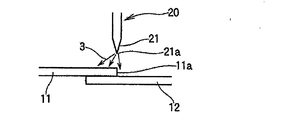
- the tip portion 21 of the electrode 20 has a single pointed tip 21 a having a tip angle ⁇ of 20 ° or more and 40 ° or less with respect to the electrode center axis 22 and has an inverted triangular shape.
- the tip portion 21 of the electrode 20 of this comparative example has an acute tip shape, but is symmetric with respect to the electrode center axis 22. This is because the tip surface 2 of the tungsten electrode 1 in the first aspect of the invention is asymmetric with respect to the electrode center axis 6 by being obliquely cut only on one side with respect to the electrode center axis 6 and is unevenly distributed on one side. It is different from having. For this reason, even if it matches with the direction and positional relationship during welding of the tungsten electrode 20, the arc from the tip 21a of the tungsten electrode 20 cannot be effectively directed to the steel material side (described later).
- the arc from the tungsten electrode tip 1 cannot be directed to the aluminum alloy material side only by the shape of the asymmetric tip surface 2 obliquely cut only on one side of the tip portion of the tungsten electrode 1.
- the direction of the tip surface 2 with respect to the aluminum alloy material 11 side and the end of the aluminum alloy material 11 which is a weld line
- the positional relationship between 11a and the only tip 2a is important.
- FIGS. 4 to 8 are explanatory diagrams showing examples of TIG welding using the electrodes of FIGS. 1 (a), 1 (b), 2, and 3 (a) and 3 (b).
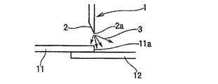
- FIG. 4 shows an example of the first invention.
- the pointed tip 2a of the tungsten electrode is located immediately above the end portion 11a of the aluminum alloy material 11 superimposed on the upper side of the steel material 12, that is, directly above the weld line, and faces downward from above.
- the tungsten electrode 11 faces the tip surface 2 of an asymmetric shape that is obliquely cut only on one side toward the aluminum alloy material 11 side.
- the arc 3 (indicated by a plurality of arrows, which is the same in the following drawings) generated from the tip 2a of the tungsten electrode 1 can be directed toward the steel material 12 as shown.
- the distribution of heat input to the aluminum alloy material / FCW / steel material can be changed with the direction of the arc directed to the steel material side.
- the movement to the aluminum alloy material 11 side of the molten metal of the aluminum alloy material 11 can be suppressed, the required amount can be moved to the steel material 12 side, and the separation of the beads can be effectively prevented.
- a joint having a good bead appearance and a high joint strength can be obtained by these synergistic effects even in the case of dissimilar metal joining by wire welding under efficient TIG construction conditions.
- the tip 2a of the electrode 1 is connected to the end 11a (welding line) of the aluminum alloy material 11 as shown in FIG. It is good to arrange at the position just above.
- the vertical direction of the electrode 1 is preferably a vertical direction in the direction perpendicular to the welding line in FIG.
- the vertical deviation from the weld line (end portion 11a) in the direction perpendicular to the weld line in FIG. It is recommended that the angle deviation is within 0.5 mm and the angle deviation is within ⁇ 5 °.
- the tip surface 2 having an asymmetric shape obtained by obliquely cutting only one side of the tungsten electrode 1 faces the aluminum alloy material 11 side (left side in FIG. 4).
- This front end surface 2 is arranged so as to be parallel to the welding direction (the direction of the welding line, the extending direction of the end portion 11a of the aluminum alloy material 11 from the front side to the back side in FIG. 4).
- the direction of the front end surface 2 does not necessarily have to be parallel to the weld line, and the direction of the front end surface 2 is slightly crossed with the weld line (the extending direction of the end of the aluminum alloy material 11). There may be.
- the allowable amount of the intersecting angle is determined by whether or not the arc 3 generated from the tip 2a of the tungsten electrode can be effectively directed to the steel material 12 side.
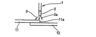
- FIGS. 5 and 6 use the tungsten electrode 1 of the first invention, the orientation of the asymmetrical tip surface 2 to the aluminum alloy material 11 side and the welding line of the only tip 2a are shown.
- the positional relationship with the end 11a of the aluminum alloy material 11 is out of the scope of the present invention. For this reason, as shown by the direction of the arc 3 in FIGS. 5 and 6, the arc 3 from the tip 2 a of the tungsten electrode is not directed to the steel material 12 side.
- the position of the sharp tip 2 a of the tungsten electrode 1 is the position of the end portion 11 a of the aluminum alloy material 11, that is, directly above the weld line, as in FIG. 4. Nevertheless, in FIG. 5, the asymmetrical tip surface 2 of the tungsten electrode faces the steel material 12 side opposite to the aluminum alloy material 11 side. In FIG. 6, the direction of the asymmetrical tip surface 2 is a direction that intersects the extending direction of the end portion 11 a of the aluminum alloy material 11 by 90 °.
- FIG. 7 is an example using the electrode 30 having the conventional tip 31 of FIG. 2, and FIG. 8 uses the electrode 20 having the tip 21 of the comparative example of FIGS. 3 (a) and 3 (b).
- the positions of the sharp tips 31a and 21a of the tungsten electrode are the positions of the end portions 11a of the aluminum alloy material 11, that is, directly above the weld line, as in FIG.
- the arc 3 generated from the tip of the tungsten electrode could not be effectively directed to the steel material 12 side.
- using the electrodes of FIGS. 3 (a) and 3 (b) can suppress the spread of the arc in the direction perpendicular to the tip line of the electrodes, and can be expected to have an effect of controlling the melting range and heating range. It was. In practice, however, the spread of the arc 3 was suppressed, but the deviation of the arc 3 toward the aluminum alloy material 11 could not be improved, and early FCW melting was difficult. Therefore, the molten metal of the aluminum alloy material 11 moves to the aluminum alloy material 11 side, mixing with the molten metal of FCW becomes insufficient, and the bead separation cannot be prevented.
- TIG welding construction The TIG welding construction of the present invention is advantageous in that a normal and efficient TIG welding apparatus and welding conditions can be used.
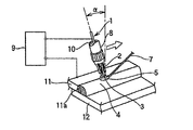
- FIG. 9 shows an example of TIG welding construction of the present invention.
- the aluminum alloy material 11 is the upper side, and the end of the aluminum alloy material 11 is on the steel material 12. Overlapped, lap joints are formed.
- FIG. 9 shows a construction example of TIG welding according to the present invention. Except for the shape and arrangement of the tip of the electrode according to the present invention shown in FIG. 4, FIG. 9 shows a general TIG welding apparatus and a construction method. And the point which can use such general purpose TIG welding is an advantage of the present invention.
- the TIG welding machine generates an arc 3 between the tungsten electrode 1 that is a non-consumable electrode and the aluminum alloy material 11 on the positive electrode side by a TIG welding power source 9 having a direct current constant current characteristic. Then, welding is performed from the left side of FIG. 9 to the right side in the direction of the arrow with the end portion 11a of the aluminum alloy material 11 as a welding line.
- the end of the upper plate, that is, the end 11a of the aluminum alloy material 11 is usually the weld line.
- FCW flux cored wire
- FIG. 9 shows a molten pool 5 and a bead 4 formed by the arc 3 (the electrode 1 in FIGS. 1A and 1B and the steel material side according to the arrangement in FIG. 4).
- the present inventors performed TIG welding by direct current TIG welding, and made the inclination of the tungsten electrode appropriate for the aluminum alloy material and steel material to be welded, and the tip of the tungsten electrode at an appropriate position.
- the second and third inventions were completed. According to the second and third aspects of the present invention, dissimilar metal joining of an aluminum alloy material and a steel material can be performed by TIG welding without causing bead separation.
- the second invention for example, as shown in FIG. 11, first, at least a part of the aluminum alloy material 11 and the steel material 12 are overlapped. Then, with the aluminum alloy material 11 side as the positive electrode, while supplying flux cored wire (FCW) 7 to the stepped portion 13 formed on the end portion 11a of the aluminum alloy material 11 and the surface of the steel material 12, a rod-shaped tungsten electrode 30 is used to generate arc 3. Thus, TIG welding of the aluminum alloy material 11 and the steel material 12 is performed.
- FCW flux cored wire
- the temperature of the steel material 12 does not rise sufficiently if the aluminum alloy material 11 is simply melted by the arc 3 irradiated from the tip of the tungsten electrode 30.
- the flux supplied from the FCW 7 does not spread on the surface of the steel material 12 and the wettability with the molten aluminum alloy cannot be improved, so that a good bead cannot be formed, and as a result, sufficient bonding strength cannot be obtained.
- the power source is changed from an AC power source generally used for welding the aluminum alloy material 11 to a DC power source. That is, TIG welding is performed by direct current TIG welding. According to DC TIG welding, the melting range of the aluminum alloy material 11 can be reduced.
- TIG welding is performed by inclining the tungsten electrode 30 in the direction opposite to the conventional fillet. That is, TIG welding is performed by tilting the tungsten electrode 30 from the direction perpendicular to the surface of the aluminum alloy material 11 toward the aluminum alloy material 11.
- the inclination of the tungsten electrode 30 is in a state where it is inclined more than 5 ° and less than 35 ° from the direction perpendicular to the surface of the aluminum alloy material 11 to the aluminum alloy material 11 side (5 ° ⁇ ⁇ 35 °).
- the tip of the tungsten electrode 30 needs to be disposed on the aluminum alloy material 11 side (left side in FIG. 11) including at least the end portion 11 a of the aluminum alloy material 11 in a direction parallel to the surface of the aluminum alloy material 11.
- the tip end portion of the tungsten electrode 30 needs to be disposed above, that is, on a perpendicular line perpendicular to the surface of the aluminum alloy material 11.
- the tip of the tungsten electrode 30 is closer to the steel material 12 than the end 11a of the aluminum alloy material 11 (right side in FIG. 11), the aluminum alloy material 11 tends to be insufficiently melted. Moreover, the heat input to the steel material 12 becomes too large, and a thick intermetallic compound layer is likely to be formed at the interface between the aluminum alloy material 11 and the steel material 12. Therefore, even if a bead is formed, sufficient joint strength cannot be obtained.
- the tip of the tungsten electrode 30 is disposed more than necessary on the side of the aluminum alloy material 11 from the end 11a of the aluminum alloy material 11, the melting of the FCW 7 becomes insufficient. Moreover, the temperature rise of the steel material 12 becomes insufficient, and the effect of improving the wettability of the flux cannot be exhibited. In this case, sufficient joint strength cannot be obtained even if beads are formed.
- the “aluminum alloy material 11 side” means a position closer to the center of the aluminum alloy material 11 starting from the end portion 11 a of the aluminum alloy material 11.
- the present invention for example, as shown in FIG. 13, first, at least a part of the aluminum alloy material 11 and the steel material 12 are overlapped. Then, with the aluminum alloy material 11 side as the positive electrode, while supplying flux cored wire (FCW) 7 to the stepped portion 13 formed on the end portion 11a of the aluminum alloy material 11 and the surface of the steel material 12, a rod-shaped tungsten electrode 30 is used to generate arc 3. Thus, TIG welding of the aluminum alloy material 11 and the steel material 12 is performed.
- FCW flux cored wire
- a torch (see FIG. 12) aiming at a stepped portion 13 formed by the end 11 a of the upper metal plate 11 and the surface of the lower metal plate 12.
- Overlap fillet welding in which the electrode 30 is inclined and welded, is a method commonly used for welding the same kind of metal plates such as steel materials or aluminum alloy materials.
- the inclination angle ⁇ of the torch (electrode 30) at this time is appropriately selected within a range in which the penetration into the upper metal plate 11 and the lower metal plate 12 is appropriate.
- one-pass fillet welding is performed in the joining of the metal plates 11 and 12 constituting a transportation vehicle such as an automobile, but if the inclination angle ⁇ of the torch (electrode 30) becomes too large, the lower side The penetration into the metal plate 12 is reduced.
- the inclination angle ⁇ of the torch (electrode) is 5 ° to 15 °.
- the surface of the steel material 12 is also secured while ensuring the melting of the aluminum alloy material 11 and the welding material FCW7. Welding conditions for heating appropriately are necessary, and the conditions are inevitably different from welding of the same kind of metal plates such as steel materials and aluminum alloy materials.
- the welding of the same kind of metal plates is the inclination angle of the tungsten electrode 30 for performing appropriate overlapped fillet welding, Further, it is considered that the target position when the arc 3 is irradiated from the tungsten electrode 30 (position where the extended line of the central axis of the tungsten electrode 30 intersects the surface of the aluminum alloy material 11) is different.
- the present inventors conducted a welding test in which the inclination angle of the tungsten electrode 30 in TIG welding and the target position when irradiating the arc 3 from the tungsten electrode 30 were changed, and conducted extensive research. As a result, the present inventors have found suitable welding conditions that can form a good bead 4.
- the bead separation preventing effect and the wettability improving effect described above are manifested by directing the arc 3 irradiated from the tungsten electrode 30 to the aluminum alloy material 11 side as much as possible. In addition, this effect is more prominent if the inclination angle of the tungsten electrode 30 is made as large as possible. However, if the inclination angle of the tungsten electrode 30 is too large, the tungsten electrode 30 comes into contact with the surface of the steel material 12, so that the inclination angle is limited. Considering this, the tungsten electrode 30 is in a state inclined from 35 ° to less than 60 ° from the direction perpendicular to the steel material 12 toward the steel material 12 (35 ° ⁇ ⁇ ⁇ 60 °).
- the target position when the arc 3 is irradiated from the tungsten electrode 30 is formed by the end 11a of the aluminum alloy material 11 and the surface of the steel material 12. If the stepped portion 13 is used, the heat input to the steel material 12 becomes too large. In this case, the steel material 12 is melted. In this case, even if the steel material 12 does not melt, a thick intermetallic compound is generated. For these reasons, even if a continuous bead can be formed, cracking may occur or sufficient joint strength may not be obtained.
- the “target position” means a position where the extension line of the central axis of the tungsten electrode 30 intersects the surface of the aluminum alloy material 11.
- the present inventors set the target position when irradiating the arc 3 from the tungsten electrode 30 to the aluminum alloy material 11 side rather than the stepped portion 13 generally performed by welding of the same kind of metal plates. That is, it was found that it is effective to use the surface of the aluminum alloy material 11.
- the target position when irradiating the arc 3 from the tungsten electrode 30 is within a range of 1.0 mm or more and less than 3.0 mm from the end 11a of the aluminum alloy material 11 to the aluminum alloy material 11 side (1. 0 mm ⁇ x ⁇ 3.0 mm).
- the “aluminum alloy material 11 side” means a position closer to the center of the aluminum alloy material 11 starting from the end 11a of the aluminum alloy material 11.
- the tip of the tungsten electrode 30 needs to be arranged at a position perpendicular to the surface of the aluminum alloy material 11 (on a perpendicular line perpendicular to the surface of the aluminum alloy material 11), and is at least 2.0 mm or more and less than 4.5 mm vertical. It is necessary to arrange at positions (2.0 mm ⁇ z ⁇ 4.5 mm) apart from each other. This position is also affected by the thickness of the aluminum alloy material 11, the inclination angle of the tungsten electrode 30, the target position of the arc 3 from the tungsten electrode 30, and the welding conditions (current voltage, welding speed, FCW supply speed). .
- the power source is changed from an AC power source generally used for welding the aluminum alloy material 11 to a DC power source. That is, TIG welding is performed by direct current TIG welding. According to DC TIG welding, the melting range of the aluminum alloy material 11 can be reduced.
- FCW 7 is preferably supplied from the welding progress direction. Further, the tungsten electrode 30 may be provided with a forward angle ⁇ of about 15 ° or less.
- FCW 7 starts to melt on the front side of the molten pool of the aluminum alloy material 11, so that both can be easily melt-mixed and a good bead 4 can be formed.
- FCW 7 is supplied from the opposite direction of the traveling direction, FCW 7 is melted behind the molten pool of aluminum alloy material 11. Therefore, it becomes difficult to melt and mix them, and it becomes difficult to form a good bead 4.
- the material of the aluminum alloy material 11, the steel material 12, the flux cored wire (FCW) 7, etc. are not specifically limited. However, it is recommended to use the materials described below as these materials.
- Aluminum alloy material As the aluminum alloy material 11 to be welded, the 3000 series, 5000 series, 6000 series, and 7000 series defined by JIS or AA standards according to the required characteristics of the vehicle body structure to be applied such as strength, molding, or corrosion resistance. Aluminum alloys such as can be used. However, from the viewpoint of reducing the thickness of the aluminum alloy material 11 in response to the demand for weight reduction of a vehicle body such as an automobile, it is preferable to use an aluminum alloy having particularly high strength and excellent formability among these aluminum alloys.
- the Si-Mg mass ratio (Si / Mg) in the component composition is 1 or more, and Si is excessively contained with respect to the Mg content.
- Si-rich 6000 series such as 6N01, 6016, 6111, and 6022 It is particularly preferable to use an aluminum alloy. The joint after welding using the aluminum alloy material 11 formed of these 6000 series aluminum alloys is subjected to an artificial aging treatment in an extremely short time of about 10 to 50 minutes at an extremely low temperature of 160 to 180 ° C. It also has a feature that it can recover the strength and elongation once lowered by the heat effect.
- the aluminum alloy material 11 is subjected to solution treatment and quenching treatment (quality symbol T4), subsequent aging treatment (quality symbol T6), and overaging treatment (quality symbol T7) after cold rolling or hot extrusion. It is used as a welding base material.
- the aluminum alloy material 11 does not necessarily have to be a plate-like cold-rolled plate as a whole, and at least the overlapping portion with the steel material 12 may be a plate shape.
- extruded shapes having various shapes can be used, and further, car body members and parts molded into a predetermined shape may be used.
- the thickness of the plate-like portion of the aluminum alloy material 11 is preferably 1 to 3 mm. When the thickness of the aluminum alloy material 11 is too thin, required strength and rigidity as an automobile member cannot be secured. On the other hand, when the thickness of the aluminum alloy material 11 is too thick, it becomes difficult to perform welding.
- the steel material 12 to be welded various steel plates or shaped steels such as mild steel, high tensile steel (High Tensile Strength Steel Sheets), and stainless steel cold-rolled steel plates can be used. Further, the steel material 12 may be a member or a part for a vehicle body obtained by molding these materials into a predetermined shape. From the viewpoint of reducing the thickness of the steel material 12 in response to the demand for weight reduction of a vehicle body such as an automobile, a high-strength steel material such as a high-strength steel plate having a known component composition including Si, Mn and the like and a tensile strength of 450 MPa or more should be used. Is preferred.
- the thickness of the welded portion of the steel material 12 is preferably 0.3 to 3.0 mm.
- the thickness of the steel material 12 is too thin, the required strength and rigidity as an automobile member cannot be ensured.
- the steel material 12 is too thick, welding is performed. Becomes difficult.
- the steel material 12 preferably has a zinc-based or aluminum-based coating layer formed on its surface for the purpose of welding efficiency and good bead formation. It doesn't matter.
- the coating layer can be formed by means such as hot dipping or thermal spraying.
- FCW 7 As the flux cored wire (FCW) 7, those conventionally marketed for joining dissimilar metals between the aluminum alloy material 11 and the steel material 12 can be used.
- FCW7 is a well-known one developed for improving the efficiency of fusion welding.
- FCW7 is used as a core material in a tubular outer shell (also called a hoop) made of a standard aluminum alloy such as A4047 or A4043 containing Si. It is filled with flux.
- the wire diameter of this FCW7 is preferably a small diameter of about 0.8 to 1.6 mm ⁇ , as is widely used for highly efficient full-automatic welding or semi-automatic welding.
- a flux it is preferable to use the flux which consists of a fluorine compound type composition called common name "Nocolok" for joining the dissimilar materials of the aluminum alloy material 11 and steel materials.
- This flux is a well-known flux in which an oxide (such as aluminum oxide) or an aluminum alloy powder is appropriately mixed in addition to the fluorine compound.
- the tungsten electrode 1 used in the examples of the present invention was manufactured by processing the tip of a commercially available tungsten electrode having a diameter of 3.2 mm ⁇ .
- the tip surface 2 is formed by being obliquely cut with respect to the electrode center axis 6 at a tip angle ⁇ of 30 °.
- the length of the tip surface 2 from the tip 2a in the direction of the electrode central axis 6 is 5.6 mm.
- the conventional tungsten electrode 30 of FIG. 2 is a commercially available tungsten electrode having a diameter of 3.2 mm ⁇ , and the tip portion 31 has a symmetrical conical shape having a tip angle of 15 ° with respect to the electrode central axis 32.
- the length in the direction of the electrode center axis 32 from the tip 31a is 6.0 mm.
- the comparative tungsten electrode 20 (FIGS. 3A and 3B) was produced by processing a commercially available tungsten electrode having a diameter of 3.2 mm ⁇ .
- the tungsten electrode 20 of the comparative example has a symmetric tip shape, and the tip angle of the tip 21 with respect to the central axis 22 is 15 °.
- the length in the direction of the electrode central axis 22 from the tip 21a of the tungsten electrode 20 is 6.0 mm.
- FCW flux cored wire
- K—Al—F system Noroclock flux
- FCW a commercially available FCW which is an alloy and has a wire diameter of ⁇ 1.2 mm is used.
- the welding conditions are DC TIG welding, the current is 80 to 120 A, the welding speed is 30 to 40 cm / min, the filler supply speed is 6 to 9 m / min, and the shielding gas is 20 L / min for Ar.
- the position of the tungsten electrode 1 (tip 2a) is directly above the end portion 11a of the aluminum alloy material 11, and the height of the electrode 1 (tip 2a) is 1.6 mm above the surface of the aluminum alloy material 11. .
- the advance angle ⁇ of the electrode 1 was 10 °, and welding was performed so that the bead length was 200 mm.
- a 6000 series (6022) aluminum alloy cold-rolled sheet having a thickness of 1.2 mm or 2.0 mm is used.
- the steel material 12 GA steel plate which is a 980 MPa class high tensile steel having a thickness of 1.4 mm is used.
- the pass ( ⁇ ) indicates that the bead 4 is continuously and satisfactorily formed over both the weld surface of the steel material 12 and the weld surface of the aluminum alloy material 11 as shown in FIG. 9.
- the wettability is good.
- the size of the bead on the welding surface side of the steel material 12 is relatively small, but the bead 4 is continuous, the wettability is appropriate, and the bead 4 is continuous.
- the state where the bead size on the weld surface side of the steel material 12 is too small and the wettability is poor is ⁇ .
- the state where the bead 4 is intermittent and the bead separation as shown in FIG.
- the tensile breaking strength is measured by cutting out two strip-shaped test pieces each having a plate width of 20 mm from the dissimilar overlapped fillet joint after TIG welding and conducting a tensile test. From the average value of the two tensile rupture strengths obtained as a result, the joint efficiency, which is the ratio to the tensile rupture strength of the A6022 aluminum alloy cold-rolled sheet as the base material, is calculated.
- This joint efficiency is the joint efficiency of a TIG welded overlapped fillet joint between A6022 aluminum alloy plates manufactured under the same welding conditions as in this example (the tensile strength of the A6022 aluminum alloy cold-rolled sheet, which is the base material of this aluminum-to-aluminum joint).
- the tensile shear strength is evaluated by comparing with the ratio to the breaking strength.
- the joint efficiency per unit weld line of the laser welded joint between these 6022 aluminum alloy plates is 60% or more. Therefore, if the joint efficiency of the TIG-welded dissimilar overlapped fillet joint is 60% or more, it is evaluated as ⁇ , when it is 40% to less than 60%, ⁇ , and when it is less than 40%, it is evaluated as ⁇ .
- Invention Examples 1 and 2 dissimilar metal joints having good bead appearance and high joint strength are obtained even by TIG welding under efficient construction conditions. That is, Invention Examples 1 and 2 are TIG welding under efficient construction conditions, and it is difficult to make them compatible with each other, separation of beads, suppression of a reaction layer (interface reaction layer) of steel and aluminum at the interface, and aluminum It is possible to ensure both melting and the like.
- Comparative Examples 1 to 5 in Table 1 as shown in Table 1, the electrode shape and arrangement are outside the conditions of the present invention. For this reason, overall, TIG welding under efficient construction conditions cannot achieve both separation of beads, suppression of the reaction layer between steel and aluminum at the interface, and ensuring of aluminum penetration, and high joint strength is obtained. Is not done.
- the reason why the comparative examples 2 and 3 using the electrode shape (electrode 1) shown in FIGS. The tip part (tip face) 2 cut obliquely is not directed to the aluminum alloy material 11 side.
- the direction of the arc 3 is as shown in FIGS. 5 and 6, and the arc 3 from the tip 2 a of the tungsten electrode 1 is not directed to the steel material 12 side.
- a welding test is performed with a configuration similar to that of FIG. That is, first, one end of the aluminum alloy material 11 is superposed on one end of the steel material 12. Then, with the aluminum alloy material 11 side as the positive electrode, while supplying flux cored wire (FCW) 7 to the stepped portion 13 formed on the end portion 11a of the aluminum alloy material 11 and the surface of the steel material 12, a rod-shaped tungsten electrode TIG welding is performed using 30.
- FCW flux cored wire
- a 6000 series (6022) aluminum alloy cold-rolled sheet having a thickness of 1.2 mm or 2.0 mm is used.
- steel material 12 a 1470 MPa class cold-rolled sheet having a thickness of 1.4 mm, a 980 MPa-class cold-rolled sheet having a thickness of 1.4 mm, or a 980 MPa-class GA steel sheet having a thickness of 1.2 mm is used.
- FCW 7 has an aluminum alloy skin material containing 10 mass% of Cs-based flux and added with 1.25 mass% of Si.
- the wire diameter of FCW7 is ⁇ 1.2 mm.
- Welding is performed by direct current TIG welding. Regarding the welding conditions, the current is 80 to 120 A, the welding speed is 30 cm / min, the filler supply speed is 6 to 10 m / min, the shielding gas is Ar gas, and the shielding gas supply speed is 20 L / min.
- the advance angle ⁇ of the tungsten electrode 30 is 10 ° to 15 °, and welding is performed so that the length of the bead 4 is 200 mm.
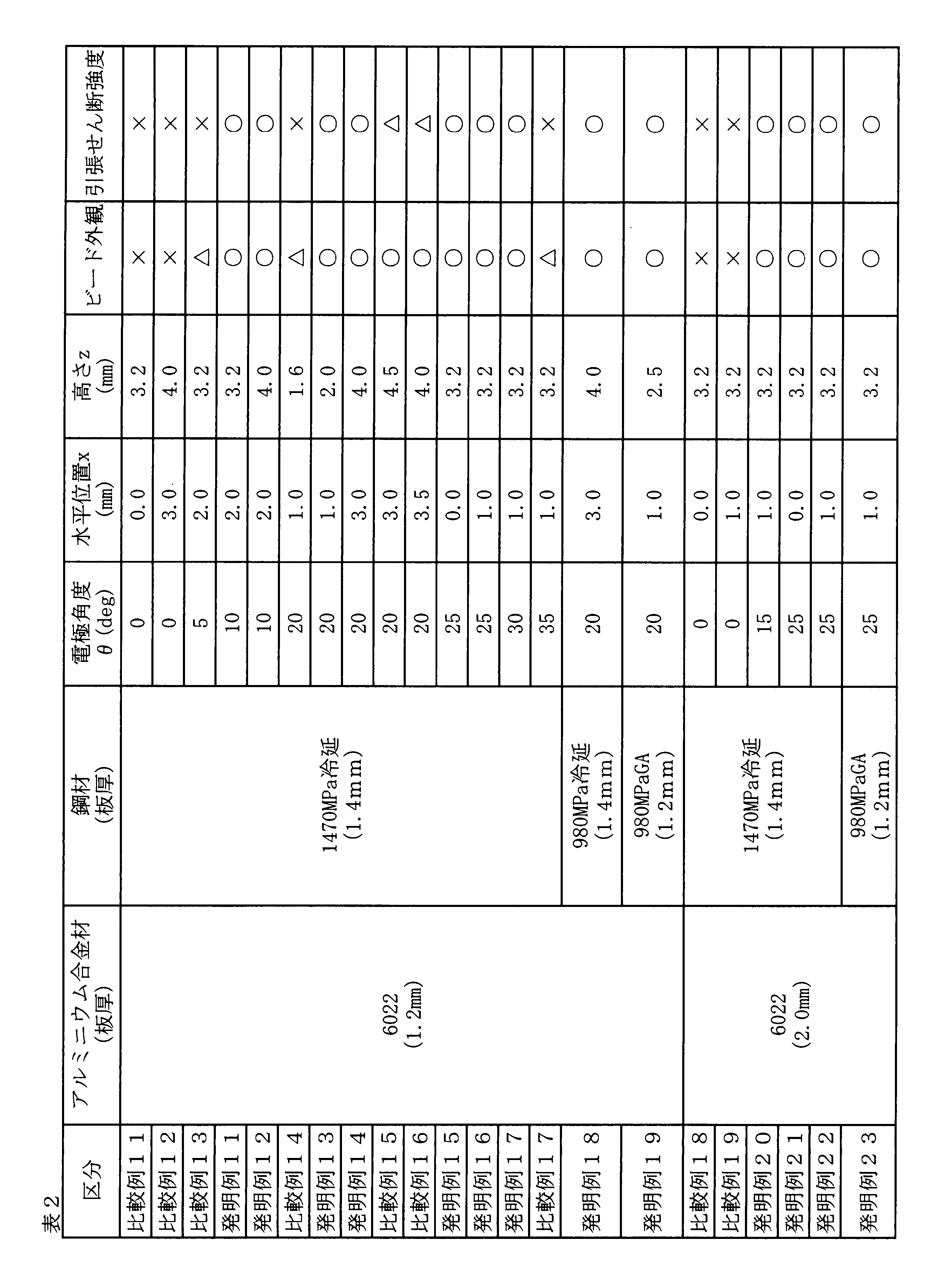
- test results are evaluated by the appearance of the formed beads 4 and the tensile shear strength (joining strength).
- the bead 4 is formed continuously and satisfactorily over both the welded surface of the aluminum alloy material 11 and the welded surface of the steel material 12, and “ ⁇ ” indicates that the wettability can be judged good. And is evaluated as passing. Although the beads 4 are continuously formed, those that can be judged to have poor wettability are indicated by “ ⁇ ”, and those that are clearly separated by beads are indicated by “ ⁇ ”, and are evaluated as rejected.
- the tensile strength at break is measured by cutting out two strip-shaped test pieces each having a plate width of 20 mm including the welded portion from the dissimilar metal joint after TIG welding and performing a tensile test. From the average value of the two tensile rupture strengths obtained as a result, the joint efficiency, which is a ratio to the tensile rupture strength of the base material 6000 (6022) aluminum alloy cold-rolled sheet, is calculated. By comparing this joint efficiency with the joint efficiency of a 6000 series (6022) aluminum alloy cold-rolled sheet fillet welded joint manufactured by TIG welding using a general aluminum alloy welding wire, the tensile shear strength (Joint strength) is evaluated.
- the joint efficiency per unit weld line of 6000 series (6022) aluminum alloy cold-rolled overlapped fillet welded joints is 60% or more. Accordingly, a joint efficiency of a TIG-welded dissimilar overlapped fillet welded joint that is at least the same level as that of aluminum alloy cold-rolled sheets is indicated by “ ⁇ ” and is evaluated as acceptable. A joint efficiency of 40% to less than 60% is indicated by “ ⁇ ”, and a joint efficiency of less than 40% is indicated by “x”. Table 2 shows the above test results.
- An inclination angle (electrode angle) ⁇ toward the aluminum alloy material side of the tungsten electrode is more than 5 ° and less than 35 ° (5 ° ⁇ ⁇ 35 °).
- the horizontal position of the tip of the tungsten electrode is in a range (0 mm ⁇ x ⁇ 3.5 mm) closer to the inner side than the end 11a of the aluminum alloy material by 0 mm or more and less than 3.5 mm.
- the height of the tip of the tungsten electrode is a position (2.0 mm ⁇ z ⁇ 4.5 mm) separated from the surface position of the aluminum alloy material by 2.0 mm or more and less than 4.5 mm.
- the appearance and tensile shear strength of the beads are both “ ⁇ ”, and excellent appearance and bonding strength are obtained. That is, it is possible to achieve both prevention of bead separation, which is difficult to be compatible with each other in TIG welding, suppression of the formation of an intermetallic compound layer (or reaction layer) at the interface, and ensuring penetration of the aluminum alloy. ing.
- Comparative Examples 11 to 13 and 17 to 19 do not satisfy the requirement regarding the inclination angle ⁇ toward the aluminum alloy material side of the tungsten electrode. Further, Comparative Example 16 does not satisfy the requirements regarding the horizontal position of the tip of the tungsten electrode, and Comparative Examples 14 and 15 do not satisfy the requirements regarding the height of the tip of the tungsten electrode. Therefore, these comparative examples resulted in failure because at least one of the appearance and tensile shear strength of the bead was “ ⁇ ” or “x”.
- a welding test is performed with a configuration similar to that of FIG. That is, first, one end of the aluminum alloy material 11 is superposed on one end of the steel material 12. Then, with the aluminum alloy material 11 side as the positive electrode, while supplying flux cored wire (FCW) 7 to the stepped portion 13 formed on the end portion 11a of the aluminum alloy material 11 and the surface of the steel material 12, a rod-shaped tungsten electrode TIG welding is performed using 30.
- FCW flux cored wire
- a 6000 series (6022) aluminum alloy cold-rolled sheet having a thickness of 1.2 mm or 2.0 mm is used.
- steel material 12 a 980 MPa class cold rolled sheet having a thickness of 1.4 mm, a 1470 MPa class cold rolled sheet having a thickness of 1.4 mm, or a 980 MPa class GA steel sheet having a thickness of 1.4 mm is used.
- FCW 7 has an aluminum alloy skin material containing 10 mass% of Cs-based flux and added with 1.25 mass% of Si.
- the wire diameter of FCW7 is ⁇ 1.2 mm.
- Welding is performed by direct current TIG welding.
- the current is 80 to 120 A
- the welding speed is 30 cm / min
- the filler supply speed is 6 to 10 m / min
- the shielding gas is Ar gas
- the shielding gas supply speed is 20 L / min.
- the advance angle ⁇ of the tungsten electrode 30 is 5 ° to 15 °, and welding is performed so that the length of the bead 4 becomes 200 mm.
- test results are evaluated by the appearance of the formed beads 4 and the tensile shear strength (joint efficiency).
- the bead 4 is formed continuously and satisfactorily over both the welded surface of the aluminum alloy material 11 and the welded surface of the steel material 12, and “ ⁇ ” indicates that the wettability can be judged good. And is evaluated as passing. Although the beads 4 are continuously formed, those that can be judged to have poor wettability are indicated by “ ⁇ ”, and those that are clearly separated by beads are indicated by “ ⁇ ”, and are evaluated as rejected. Is done.
- the tensile strength at break is measured by cutting out two strip-shaped test pieces each having a plate width of 20 mm including the welded portion from the dissimilar metal joint after TIG welding and performing a tensile test. From the average value of the two tensile rupture strengths obtained as a result, the joint efficiency, which is a ratio to the tensile rupture strength of the base material 6000 (6022) aluminum alloy cold-rolled sheet, is calculated. By comparing this joint efficiency with the joint efficiency of a 6000 series (6022) aluminum alloy cold-rolled sheet fillet welded joint manufactured by TIG welding using a general aluminum alloy welding wire, the tensile shear strength (Joint strength) is evaluated.
- the joint efficiency per unit weld line of 6000 series (6022) aluminum alloy cold-rolled overlapped fillet welded joints is 60% or more. Accordingly, a joint efficiency of a TIG-welded dissimilar overlapped fillet welded joint that is at least the same level as that of aluminum alloy cold-rolled sheets is indicated by “ ⁇ ” and is evaluated as acceptable. A joint efficiency of 40% to less than 60% is indicated by “ ⁇ ”, and a joint efficiency of less than 40% is indicated by “x”. Table 3 shows the above test results.
- the inclination angle (electrode angle) ⁇ toward the steel material side of the tungsten electrode is 35 ° or more and less than 60 ° (35 ° ⁇ ⁇ ⁇ 60 °).
- the target position of the arc from the tungsten electrode is arranged in a range (1.0 mm ⁇ x ⁇ 3.0 mm) closer to the inside of 1.0 mm or more and less than 3.0 mm from the end 11a of the aluminum alloy material.
- the tip of the tungsten electrode is disposed at a height that is a position (2.0 mm ⁇ z ⁇ 4.5 mm) away from the surface position of the aluminum alloy material by 2.0 mm or more and less than 4.5 mm.
- the appearance and tensile shear strength of the beads are both “ ⁇ ”, and excellent appearance and bonding strength are obtained.
- TIG welding it is possible to achieve both prevention of bead separation, suppression of the formation of an intermetallic compound layer (or reaction layer) at the interface, and ensuring of aluminum alloy penetration.
- Comparative Examples 31 to 35 and 36 to 40 do not satisfy the requirement (35 ° ⁇ ⁇ ⁇ 60 °) regarding the inclination angle (electrode angle) ⁇ toward the steel material side of the tungsten electrode. Further, Comparative Examples 31, 33, 37, 39, and 40 do not satisfy the requirement (1.0 mm ⁇ x ⁇ 3.0 mm) regarding the target position x of the arc from the tungsten electrode. Further, Comparative Examples 33, 36, 37, and 40 do not satisfy the requirement (2.0 mm ⁇ z ⁇ 4.5 mm) regarding the height z of the tip of the tungsten electrode. As a result, in these comparative examples, at least one of the appearance and the tensile shear strength of the beads was “ ⁇ ” or “ ⁇ ”, and the result was a failure.
- the dissimilar metal joining method of the present invention when TIG welding is applied to dissimilar metal joining between an aluminum alloy material and a steel material, “separation of beads” can be prevented, and a dissimilar metal welded joint (dissimilar metal joining) having high joining strength can be prevented. Part) is obtained.
- the dissimilar metal joining method of the present invention can be usefully applied as a welding method for various dissimilar material structural members in the transportation field such as automobiles and railway vehicles, machine parts, building structures, and the like.
Landscapes
- Engineering & Computer Science (AREA)
- Mechanical Engineering (AREA)
- Physics & Mathematics (AREA)
- Plasma & Fusion (AREA)
- Chemical & Material Sciences (AREA)
- Materials Engineering (AREA)
- Arc Welding In General (AREA)
- Butt Welding And Welding Of Specific Article (AREA)
Abstract
Description
本発明者らの知見によれば、アルミニウム合金材と鋼材との重ね継手のTIG溶接における「ビードの分かれ」の発生原因は、汎用されるタングステン電極から発生するアークがアルミニウム合金材側に片寄る(偏る)ことである。アークのアルミニウム合金材側への偏りによって、鋼材側の温度が十分に上昇せず、FCWより供給されるフラックスが鋼板上に広がらず、アルミ溶湯と鋼板との濡れ性が改善できない。
これを、図10を用いてより具体的に説明する。
タングステン電極30から発生するアーク3がアルミニウム合金材11側に偏ると、アルミニウム合金材11が先に溶融し始め、FCW7の溶融開始は必然的に遅れることとなる。その結果、鋼材12の表面にフラックスが十分に広がらず、アルミニウム合金材11における鋼材12側のビードとなるべきアルミニウム合金溶湯の鋼材12側への濡れ性確保が困難となる。また、アルミニウム合金材11側へのアーク3の偏りによって、鋼材12の温度上昇も相対的に遅くなるため、鋼材12の表面へのフラックスの広がりが阻害されているものと考えられる。
このようなビードの分かれの機構を抑制してビードの分かれの発生を防止するためには、一般的には以下の方策(1)(2)が必要であると当業者であれば考える。すなわち、(1)できるだけ早くFCW7を溶融させ、濡れ性を確保する。(2)アルミニウム合金材11の溶融範囲を抑制し、アルミ溶湯のアルミニウム合金材11側への移動を小さくする。ただし、アルミニウム合金材11の厚み(板厚)方向全域にわたる溶融は確保する必要がある。
図10のタングステン電極(トーチ)30の位置を鋼材12の側(図10の右側)に0.5mm移動させることにより、アルミニウム合金材11側への入熱を減少させることが考えられる。しかし、電極の先端とアルミニウム合金材11上端部との間で、より強いアーク3が発生するため、ビードの分かれの発生防止効果は小さかった。また、鋼材12側へ1mm移動すると、電極30と鋼材12の間でアーク3が強く発生し、鋼材が溶融しはじめ、接合自体ができなかった。
アルミニウム合金と鋼の溶接においては、鋼の溶融を避けてアルミニウム合金のみを溶融させるため、一般的にアルミニウム合金板の上方から入熱を行う。しかし、図10において、アルミニウム合金材11の溶融範囲を抑制するため、タングステン電極(トーチ)30が溶接線と直交したまま板の法線方向に対して10°傾斜するようにして、その先端がアルミニウム合金材11と鋼材12との重ね部を狙うようにして溶接を行った。この結果、アルミニウム合金材11側の溶融は若干抑制できたが、ビードの分かれの完全な防止には至らなかった。
図10において、交流電源から直流電源へと電源を変更することにより、アルミニウム合金材11側へのアーク3の広がりが抑制でき、アルミニウム合金材11の溶融範囲は小さくなった。しかしながら、この場合でも、ビードの分かれの抑制までには至らなかった。
(電極の先端部形状)
まず、図1~3を参照して、第1発明におけるTIG溶接用の電極の先端部の形状(偏芯先端部形状)を具体的に説明する。図1(a)は本発明におけるTIG溶接用のタングステン電極の先端部を示す側面図であり、(b)は(a)に示されたタングステン電極の先端部を示す正面図である。図2は従来の電極の円錐型形状の先端部を示す正面図である。図3(a)は比較例の電極の先端部を示す側面図であり、(b)は(a)に示されたタングステン電極の先端部を示す正面図である。
前記した通り、タングステン電極1の先端部の一方側のみ斜め切りされた非対称な先端面2の形状だけでは、このタングステン電極先端1からのアークをアルミニウム合金材側に指向させるようにはできない。タングステン電極1の先端2aからのアークを鋼材側に指向させるためには、図4に示すように、アルミニウム合金材11側に対する先端面2の向きと、溶接線であるアルミニウム合金材11の端部11aと唯一の先端2aとの位置関係が重要である。
本発明のTIG溶接施工は、通常の効率の良いTIG溶接装置や溶接条件が使用できる点で有利である。図9は、本発明のTIG溶接施工の一例を示す。
ここで、FCW(フラックス入りワイヤ)を活用したTIG溶接を用いて重ねすみ肉溶接などを行う場合には、図4、9に示すように、通常、アルミニウム合金材11の上側に配置された電極1から下向きにアークを発生させる。このような溶接施工方向に対して、アルミニウム合金材11(端部)を上側、鋼材12(端部)を下側として互いに重ね合わせ、溶接する。継手におけるこのような位置関係は、鋼材12とアルミニウム合金材11との両方の溶接面にわたってアルミニウム溶接材料による良好なビードを形成し、高い接合強度の異種金属接合体(継手)を得るために好ましい。
図9は、本発明に係るTIG溶接の施工例を示している。前記した図4の本発明による電極の先端部形状や配置関係を除いては、図9は一般的なTIG溶接装置や施工方法の態様を示している。そして、このような汎用TIG溶接を用いることができる点が本発明の利点である。
以下、本件第2発明を添付図面に示す実施形態に基づいて更に詳細に説明する。
まず、電源は、一般的にアルミニウム合金材11の溶接に用いられている交流電源から直流電源へと変更される。すなわち、TIG溶接は、直流TIG溶接で行われる。直流TIG溶接によれば、アルミニウム合金材11の溶融範囲を減少させることができる。
図11においては、あえて従来の重ねすみ肉とは逆方向にタングステン電極30を傾けてTIG溶接が行なわれている。すなわち、タングステン電極30をアルミニウム合金材11の表面に垂直な方向からアルミニウム合金材11側に向けて倒してTIG溶接が行なわれている。その結果、本発明者らは、これまでの技術常識に反し、ビードの分かれを起こすことなく安定してビード形成ができる条件があることを見出した。
タングステン電極30の先端部は、アルミニウム合金材11の表面と平行な方向で、少なくともアルミニウム合金材11の端部11aを含むアルミニウム合金材11側(図11では左側)に配置する必要がある。且つ、タングステン電極30の先端部は、上方、すなわちアルミニウム合金材11の表面と直交する垂線上に配置する必要がある。
次に、本件第3発明を添付図面に示す実施形態に基づいて更に詳細に説明する。
このようにアルミニウム合金材11と鋼材12を重ねすみ肉溶接する異種金属接合では、同じ種類の金属板同士の溶接とは、適正な重ねすみ肉溶接を行うための、タングステン電極30の傾斜角度、また、タングステン電極30からアーク3を照射するときの狙い位置(タングステン電極30の中心軸の延長線がアルミニウム合金材11の表面と交わる位置)が異なってくると考えられる。
タングステン電極30を、鋼材12に垂直な方向から鋼材12側に向けて傾斜させると、タングステン電極30から照射されるアーク3が、相対的にアルミニウム合金材11側に向かう。これにより、FCW7の溶湯をアルミニウム合金材11側に押しやる作用が発生する。その結果、アルミニウム合金材11の溶湯とFCW7の溶湯が一体化し、ビードの分かれ防止効果を得ることができる。その効果は、タングステン電極30の傾斜が30°以上になると徐々に表れ始める。また、FCW7が早期に溶融するため、フラックスの濡れ性改善効果も発現しやすくなる。その効果はタングステン電極30の傾斜が35°以上になると発現し、引張せん断強度も得られやすくなると考えられる。
同じ種類の金属板同士の溶接で一般的に行われているように、タングステン電極30からアーク3を照射するときの狙い位置を、アルミニウム合金材11の端部11aと鋼材12の表面で形成された段状部13とすると、鋼材12への入熱が大きくなりすぎる。この場合、鋼材12が溶融してしまう。また、この場合には、鋼材12の溶融に至らなくても、厚い金属間化合物が生成してしまう。これらの理由により、連続ビードが形成できても割れが発生したり、十分な継手強度が得られなくなったりする。尚、当該「狙い位置」は、タングステン電極30の中心軸の延長線がアルミニウム合金材11の表面と交わる位置を意味する。
タングステン電極30の先端部は、アルミニウム合金材11の表面から垂直に離れた位置(アルミニウム合金材11の表面と直交する垂線上)に配置する必要があり、少なくとも2.0mm以上4.5mm未満垂直に離れた位置(2.0mm≦z<4.5mm)に配置する必要がある。尚、この位置は、アルミニウム合金材11の板厚、タングステン電極30の傾斜角度、タングステン電極30からのアーク3の狙い位置、更に溶接条件(電流電圧、溶接速度、FCW供給速度)の影響も受ける。
まず、電源は、一般的にアルミニウム合金材11の溶接に用いられている交流電源から直流電源へと変更される。すなわち、TIG溶接は、直流TIG溶接で行われる。直流TIG溶接によれば、アルミニウム合金材11の溶融範囲を減少させることができる。
以上説明した条件が本件第1~第3発明それぞれの必須条件であるが、FCW7は溶接進行方向から供給することが好ましい。また、タングステン電極30には、15°以内程度の前進角αを設けても良い。FCW7を溶接進行方向から供給した場合、アルミニウム合金材11の溶融プールの前側でFCW7が溶融を開始するため、両者の溶融混合が容易であり、良好なビード4を形成することができる。進行方向と逆からFCW7が供給されると、アルミニウム合金材11の溶融プールの後ろ側でFCW7が溶融する。そのため、両者の溶融混合が困難となり、良好なビード4の形成が難しくなる。
被溶接材であるアルミニウム合金材11としては、強度や成形、または耐食性など適用する車体構造などの要求特性に応じて、JISまたはAA規格で規定される3000系、5000系、6000系、7000系などのアルミニウム合金が使用可能である。但し、自動車などの車体軽量化の要求に対するアルミニウム合金材11の薄肉化という観点からは、これらアルミニウム合金の中でも、特に高強度で且つ成形性にも優れたアルミニウム合金を用いることが好ましい。
被溶接材である鋼材12としては、軟鋼、高張力鋼(High Tensile Strength Steel Sheets)、ステンレス鋼の冷延鋼板など、種々の鋼板または形鋼を用いることができる。また、鋼材12は、これらの素材を所定形状に成形加工した車体用の部材、部品などであってもよい。尚、自動車などの車体軽量化の要求に対する鋼材12の薄肉化という観点からは、Si、Mnなどを含む公知の成分組成と450MPa以上の引張強度を有する高張力鋼板などの高張力鋼材を用いることが好ましい。
フラックスコアードワイヤ(FCW)7としては、アルミニウム合金材11と鋼材12との異種金属接合用として従来から市販されているものなどを用いることができる。このようなFCW7は、溶融溶接の効率化のために開発された周知のものであり、例えばSiを含有するA4047やA4043などの規格アルミニウム合金製の管状の外皮(フープとも言う)に、心材としてフラックスが充填されたものである。
以下に本件第1発明の実施例を説明する。図9の溶接施工態様において、タングステン電極の先端部形状とアルミニウム合金材11側との向き(配置、位置関係)を、図4~8のように種々変更した。そして、アルミニウム合金板の端部を鋼板端部上に重ねてTIG溶接することにより、種々の異材溶接接合継手が作成された。表1は、ビード外観、継手の引張せん断強度(接合強度)を各々評価した結果を示す。
フラックスコアードワイヤ(FCW)7としては、粉末フラックスとして5質量%のK-Al-F系(ノコロックフラックス)を含有し、皮材(フープ)が1.25質量%のSiを添加したアルミニウム合金であり、線径がφ1.2mmの市販のFCWが用いられる。
ビード4の外観の評価において、合格(◎)は、図9のように、ビード4が鋼材12の溶接面とアルミニウム合金材11の溶接面との両方にわたって連続して良好に形成されている、濡れ性が良好な状態である。また、これとの比較で、鋼材12の溶接面側のビードの大きさが比較的小さいが、ビード4が連続しており、濡れ性が適正な状態が○であり、ビード4が連続しているが、鋼材12の溶接面側のビードの大きさが小さすぎ、濡れ性が不良な状態が△である。そして、ビード4が断続的であり、図10のようなビードの分かれが生じている状態が×である。
TIG溶接後の異材重ねすみ肉継手から、板幅20mmの短冊状試験片を2本ずつ切り出して引張試験を行うことにより、引張破断強度が測定される。この結果得られた2つの引張破断強度の平均値から、母材であるA6022アルミニウム合金冷延板の引張破断強度に対する割合である継手効率が算出される。この継手効率を、本例と同じ溶接条件で製作されたA6022アルミニウム合金板同士のTIG溶接重ねすみ肉継手の継手効率(このアルミ同士の継手の、母材であるA6022アルミニウム合金冷延板の引張破断強度に対する割合)と比較することで、引張せん断強度が評価される。この6022アルミニウム合金板同士のレーザ溶接継手の単位溶接線当たりの継手効率は60%以上である。そのため、TIG溶接した異材重ねすみ肉継手の継手効率が60%以上であれば○、40%~60%未満であれば△、40%未満であれば×と評価される。

以下に本件第2発明の実施例を説明する。第2発明の実施例においては、図9に類似した構成で溶接試験が実施される。すなわち、まず、アルミニウム合金材11の一端部を鋼材12の一端部の上に重ね合わせる。そして、アルミニウム合金材11側を正極として、アルミニウム合金材11の端部11aと鋼材12の表面で形成された段状部13にフラックスコアードワイヤ(FCW)7を供給しながら、棒状のタングステン電極30を用いてTIG溶接が行われる。
以下に本件第3発明の実施例を説明する。第3発明の実施例においては、図9に類似した構成で溶接試験が実施される。すなわち、まず、アルミニウム合金材11の一端部を鋼材12の一端部の上に重ね合わせる。そして、アルミニウム合金材11側を正極として、アルミニウム合金材11の端部11aと鋼材12の表面で形成された段状部13にフラックスコアードワイヤ(FCW)7を供給しながら、棒状のタングステン電極30を用いてTIG溶接が行われる。

2…先端面
2a…先端
3…アーク
4、4a、4b…ビード
7…フラックスコアードワイヤ(FCW)
11…アルミニウム合金材
11a…端部
12…鋼材
13…段状部
Claims (5)
- アルミニウム合金材と鋼材の少なくとも一部を重ね合わせ、前記アルミニウム合金材側を正極として、前記アルミニウム合金材の端部と前記鋼材の表面とで形成された段状部にフラックスコアードワイヤを供給しながら、棒状のタングステン電極を用いた直流TIG溶接により前記アルミニウム合金材と前記鋼材とをすみ肉溶接する異種金属接合方法であって、
前記タングステン電極は、前記タングステン電極の中心軸に対して非対称な形状の先端部を備え、
前記先端部は、前記中心軸に対して20°以上40°以下の角度で形成された先端面を有し、
溶接中、前記タングステン電極の先端が前記鋼材側を向くように、且つ、前記先端面が前記アルミニウム合金材側に向かうように、前記タングステン電極を前記アルミニウム合金材の上方側から溶接線に向けることにより、前記タングステン電極の前記先端から発生するアークが前記鋼材側に指向されることを特徴とする異種金属接合方法。 - 前記タングステン電極の前記先端の位置が、前記アルミニウム合金材の溶接線の直上である請求項1に記載の異種金属接合方法。
- アルミニウム合金材と鋼材の少なくとも一部を重ね合わせ、前記アルミニウム合金材側を正極として、前記アルミニウム合金材の端部と前記鋼材の表面とで形成された段状部にフラックスコアードワイヤを供給しながら、棒状のタングステン電極を用いた直流TIG溶接により前記アルミニウム合金材と前記鋼材とをすみ肉溶接する異種金属接合方法であって、
溶接中、前記タングステン電極を、前記アルミニウム合金材に垂直な方向から前記アルミニウム合金材側に5°超35°未満の角度で傾けた状態で、前記タングステン電極の先端部を、前記アルミニウム合金材に平行な方向で前記アルミニウム合金材の端部から前記アルミニウム合金材側へ0mm以上3.5mm未満の範囲の位置、且つ、前記アルミニウム合金材の表面から2.0mm以上4.5mm未満垂直に離れた位置に配置することを特徴とする異種金属接合方法。 - アルミニウム合金材と鋼材の少なくとも一部を重ね合わせ、前記アルミニウム合金材側を正極として、前記アルミニウム合金材の端部と前記鋼材の表面とで形成された段状部にフラックスコアードワイヤを供給しながら、棒状のタングステン電極を用いた直流TIG溶接により前記アルミニウム合金材と前記鋼材とをすみ肉溶接する異種金属接合方法であって、
溶接中、前記タングステン電極を前記鋼材に垂直な方向から前記鋼材側に35°以上60°未満傾けた状態で、前記タングステン電極の先端部を前記アルミニウム合金材の表面から2.0mm以上4.5mm未満垂直に離れた位置に配置して、前記タングステン電極の中心軸の延長線が前記アルミニウム合金材の表面と交わる位置を前記アルミニウム合金材の端部から前記アルミニウム合金材側へ1.0mm以上3.0mm未満の範囲に配置することを特徴とする異種金属接合方法。 - 前記フラックスコアードワイヤを溶接進行方向から供給する請求項1~4のいずれか1項に記載の異種金属接合方法。
Priority Applications (4)
| Application Number | Priority Date | Filing Date | Title |
|---|---|---|---|
| DE112012001128T DE112012001128T5 (de) | 2011-03-07 | 2012-02-29 | Verfahren zum Verbinden unterschiedlicher Metalle |
| US14/003,363 US9339887B2 (en) | 2011-03-07 | 2012-02-29 | Method for bonding dissimilar metals to each other |
| KR1020137023474A KR101455953B1 (ko) | 2011-03-07 | 2012-02-29 | 이종 금속 접합 방법 |
| CN201280012117.0A CN103415369B (zh) | 2011-03-07 | 2012-02-29 | 异种金属接合方法 |
Applications Claiming Priority (6)
| Application Number | Priority Date | Filing Date | Title |
|---|---|---|---|
| JP2011049249A JP5600619B2 (ja) | 2011-03-07 | 2011-03-07 | 異材接合方法 |
| JP2011-049249 | 2011-03-07 | ||
| JP2011210460A JP5600653B2 (ja) | 2011-09-27 | 2011-09-27 | 異種金属接合方法 |
| JP2011210459A JP5600652B2 (ja) | 2011-09-27 | 2011-09-27 | 異種金属接合方法 |
| JP2011-210460 | 2011-09-27 | ||
| JP2011-210459 | 2011-09-27 |
Publications (1)
| Publication Number | Publication Date |
|---|---|
| WO2012121086A1 true WO2012121086A1 (ja) | 2012-09-13 |
Family
ID=46798054
Family Applications (1)
| Application Number | Title | Priority Date | Filing Date |
|---|---|---|---|
| PCT/JP2012/055143 Ceased WO2012121086A1 (ja) | 2011-03-07 | 2012-02-29 | 異種金属接合方法 |
Country Status (5)
| Country | Link |
|---|---|
| US (1) | US9339887B2 (ja) |
| KR (1) | KR101455953B1 (ja) |
| CN (2) | CN105149750B (ja) |
| DE (1) | DE112012001128T5 (ja) |
| WO (1) | WO2012121086A1 (ja) |
Cited By (6)
| Publication number | Priority date | Publication date | Assignee | Title |
|---|---|---|---|---|
| CN103934551A (zh) * | 2014-04-18 | 2014-07-23 | 重庆大学 | 表面机械研磨处理和超声波协同辅助异种金属tig熔-钎焊方法 |
| WO2015009769A1 (en) * | 2013-07-16 | 2015-01-22 | Illinois Tool Works Inc. | Additive manufacturing systems for and a method of surface overlay before joining, using a plurality of anchoring materials and temperature control device |
| US10421159B2 (en) | 2015-02-25 | 2019-09-24 | Hobart Brothers Llc | Systems and methods for additive manufacturing using aluminum metal-cored wire |
| US10792682B2 (en) | 2017-10-02 | 2020-10-06 | Illinois Tool Works Inc. | Metal manufacturing systems and methods using mechanical oscillation |
| US10974337B2 (en) | 2015-08-17 | 2021-04-13 | Illinois Tool Works Inc. | Additive manufacturing systems and methods |
| US11370068B2 (en) | 2015-02-25 | 2022-06-28 | Hobart Brothers Llc | Systems and methods for additive manufacturing using aluminum metal-cored wire |
Families Citing this family (13)
| Publication number | Priority date | Publication date | Assignee | Title |
|---|---|---|---|---|
| US10124437B2 (en) * | 2013-08-19 | 2018-11-13 | Covidien Lp | Laser welding of nickel titanium alloys |
| JP5847209B2 (ja) * | 2014-01-21 | 2016-01-20 | 株式会社神戸製鋼所 | 異種金属接合体及び異種金属接合体の製造方法 |
| DE102014002213B4 (de) * | 2014-02-21 | 2016-01-14 | MHIW b.v. | Verfahren und Brennerkopf zum Metall-Schutzgas-Schweißen |
| CN108136528B (zh) * | 2015-09-14 | 2020-09-29 | 日本制铁株式会社 | 角焊方法和角焊接头 |
| EP3254795A1 (en) * | 2016-06-09 | 2017-12-13 | Outokumpu Oyj | Resistance spot welding electrode and use of the electrode |
| JP2018051570A (ja) * | 2016-09-26 | 2018-04-05 | 株式会社神戸製鋼所 | 異材接合用スポット溶接法、接合補助部材、及び、異材溶接継手 |
| KR102094678B1 (ko) * | 2018-03-22 | 2020-04-01 | 케이제이에프 주식회사 | 튜브시트 자동 오버레이 용접 장치 |
| KR102529451B1 (ko) | 2018-07-10 | 2023-05-08 | 현대자동차주식회사 | 알루미늄-스틸 브레이징을 위한 필러와이어 |
| CN109175562B (zh) * | 2018-09-13 | 2020-10-30 | 湖北汽车工业学院 | 一种铜铝异种金属tig钎焊工艺 |
| CN114340833B (zh) * | 2019-08-27 | 2024-03-19 | 株式会社神户制钢所 | 异种材料接合结构体的制造方法和异种材料接合结构体 |
| CN111014900B (zh) * | 2019-11-25 | 2022-01-14 | 四川航天长征装备制造有限公司 | 一种防止铝钢异种金属过渡管接头装焊开裂的方法 |
| CN113664330B (zh) * | 2021-08-31 | 2022-10-25 | 江南造船(集团)有限责任公司 | 一种燃料舱波纹板与角钢过渡区域连续焊接方法 |
| CN116197537A (zh) * | 2022-12-30 | 2023-06-02 | 大连理工大学 | 一种镁/钢异种金属汽车车门搭接焊方法 |
Citations (2)
| Publication number | Priority date | Publication date | Assignee | Title |
|---|---|---|---|---|
| JP2010201448A (ja) * | 2009-03-02 | 2010-09-16 | Kobe Steel Ltd | 異材接合用溶加材及び異材接合方法 |
| JP2011036918A (ja) * | 2010-09-22 | 2011-02-24 | Kobe Steel Ltd | 異材接合用溶加材及び異材接合方法 |
Family Cites Families (21)
| Publication number | Priority date | Publication date | Assignee | Title |
|---|---|---|---|---|
| JPS4623133Y1 (ja) | 1966-10-04 | 1971-08-10 | ||
| US4532409A (en) * | 1981-04-06 | 1985-07-30 | Kabushiki Kaisha Kobe Seiko Sho | Method for gas shielded arc welding with direct current non-consumable electrode |
| JPS61226185A (ja) * | 1985-03-29 | 1986-10-08 | Mitsubishi Heavy Ind Ltd | Tig溶接方法 |
| JP2536286B2 (ja) | 1992-03-04 | 1996-09-18 | 株式会社竹屋 | パチンコ島台における空気清浄装置 |
| JPH06328287A (ja) | 1993-05-14 | 1994-11-29 | Nippon Steel Corp | Tig溶接用電極棒 |
| JP3700405B2 (ja) * | 1998-08-26 | 2005-09-28 | 石川島播磨重工業株式会社 | Tig溶接トーチ |
| JP3091843B1 (ja) | 1999-08-03 | 2000-09-25 | 株式会社レーザー応用工学研究所 | 溶融溶接方法 |
| JP2004237326A (ja) * | 2003-02-06 | 2004-08-26 | Aiko Engineering Kk | 狭開先tig溶接装置 |
| WO2007094203A1 (ja) * | 2006-02-17 | 2007-08-23 | Kabushiki Kaisha Kobe Seiko Sho | 異材接合用フラックスコアードワイヤおよび異材接合方法 |
| JP4256886B2 (ja) | 2006-09-14 | 2009-04-22 | 株式会社神戸製鋼所 | 異材接合用フラックスコアードワイヤおよび異材接合方法 |
| JP2008105056A (ja) | 2006-10-25 | 2008-05-08 | Denso Corp | Tig溶接方法およびその装置 |
| JP5014834B2 (ja) * | 2007-02-27 | 2012-08-29 | 住友軽金属工業株式会社 | アルミニウム材と鋼材のmig溶接方法 |
| JP5014833B2 (ja) * | 2007-02-27 | 2012-08-29 | 住友軽金属工業株式会社 | アルミニウム材と鋼材のmig溶接方法 |
| CN101195187B (zh) * | 2007-12-20 | 2010-06-09 | 山东大学 | 一种铁铝金属间化合物与钢的脉冲熔焊方法 |
| CN101284339B (zh) * | 2008-01-18 | 2010-06-23 | 哈尔滨工业大学 | 一种焊丝和其应用于铝及铝合金与钢焊接的方法 |
| JP5226564B2 (ja) | 2009-03-11 | 2013-07-03 | 株式会社神戸製鋼所 | 異材接合方法 |
| JP5457759B2 (ja) | 2009-08-25 | 2014-04-02 | キヤノン株式会社 | 半導体装置の製造方法 |
| CN101745709B (zh) * | 2009-12-21 | 2011-06-08 | 哈尔滨工业大学 | 适用于铝/钢异种合金对接的辅助涂层tig熔-钎焊方法 |
| CN101804499A (zh) * | 2010-02-02 | 2010-08-18 | 大连理工大学 | 一种直接焊接铝和无镀层钢的方法 |
| JP2011210459A (ja) | 2010-03-29 | 2011-10-20 | Kumamoto Univ | 超臨界非平衡プラズマ生成装置及び発生方法 |
| JP5525302B2 (ja) | 2010-03-29 | 2014-06-18 | 新明和工業株式会社 | 端子打機 |
-
2012
- 2012-02-29 CN CN201510670529.9A patent/CN105149750B/zh not_active Expired - Fee Related
- 2012-02-29 US US14/003,363 patent/US9339887B2/en not_active Expired - Fee Related
- 2012-02-29 DE DE112012001128T patent/DE112012001128T5/de not_active Withdrawn
- 2012-02-29 CN CN201280012117.0A patent/CN103415369B/zh not_active Expired - Fee Related
- 2012-02-29 WO PCT/JP2012/055143 patent/WO2012121086A1/ja not_active Ceased
- 2012-02-29 KR KR1020137023474A patent/KR101455953B1/ko not_active Expired - Fee Related
Patent Citations (2)
| Publication number | Priority date | Publication date | Assignee | Title |
|---|---|---|---|---|
| JP2010201448A (ja) * | 2009-03-02 | 2010-09-16 | Kobe Steel Ltd | 異材接合用溶加材及び異材接合方法 |
| JP2011036918A (ja) * | 2010-09-22 | 2011-02-24 | Kobe Steel Ltd | 異材接合用溶加材及び異材接合方法 |
Cited By (15)
| Publication number | Priority date | Publication date | Assignee | Title |
|---|---|---|---|---|
| CN105531060B (zh) * | 2013-07-16 | 2020-09-08 | 伊利诺斯工具制品有限公司 | 用于在接合之前使用多种锚固材料来进行表面覆盖的叠加制造系统和方法 |
| US11833623B2 (en) | 2013-07-16 | 2023-12-05 | Illinois Tool Works Inc. | Additive manufacturing system for joining and surface overlay |
| WO2015009639A1 (en) * | 2013-07-16 | 2015-01-22 | Illinois Tool Works Inc. | Additive manufacturing systems for and a method of surface overlay before joining, using a plurality of anchoring materials |
| CN105531060A (zh) * | 2013-07-16 | 2016-04-27 | 伊利诺斯工具制品有限公司 | 用于在接合之前使用多种锚固材料来进行表面覆盖的叠加制造系统和方法 |
| US20250108445A1 (en) * | 2013-07-16 | 2025-04-03 | Illinois Tool Works Inc. | Additive manufacturing heating control systems and methods |
| US10543549B2 (en) | 2013-07-16 | 2020-01-28 | Illinois Tool Works Inc. | Additive manufacturing system for joining and surface overlay |
| WO2015009769A1 (en) * | 2013-07-16 | 2015-01-22 | Illinois Tool Works Inc. | Additive manufacturing systems for and a method of surface overlay before joining, using a plurality of anchoring materials and temperature control device |
| US10875116B2 (en) | 2013-07-16 | 2020-12-29 | Illinois Tool Works Inc. | Additive manufacturing heating control systems and methods |
| US12083633B2 (en) | 2013-07-16 | 2024-09-10 | Illinois Tool Works Inc. | Additive manufacturing heating control systems and methods |
| CN103934551A (zh) * | 2014-04-18 | 2014-07-23 | 重庆大学 | 表面机械研磨处理和超声波协同辅助异种金属tig熔-钎焊方法 |
| US11370068B2 (en) | 2015-02-25 | 2022-06-28 | Hobart Brothers Llc | Systems and methods for additive manufacturing using aluminum metal-cored wire |
| US10421159B2 (en) | 2015-02-25 | 2019-09-24 | Hobart Brothers Llc | Systems and methods for additive manufacturing using aluminum metal-cored wire |
| US10974337B2 (en) | 2015-08-17 | 2021-04-13 | Illinois Tool Works Inc. | Additive manufacturing systems and methods |
| US10792682B2 (en) | 2017-10-02 | 2020-10-06 | Illinois Tool Works Inc. | Metal manufacturing systems and methods using mechanical oscillation |
| US12145223B2 (en) | 2017-10-02 | 2024-11-19 | Illinois Tool Works Inc. | Metal manufacturing systems and methods using mechanical oscillation |
Also Published As
| Publication number | Publication date |
|---|---|
| KR101455953B1 (ko) | 2014-10-28 |
| US20130341306A1 (en) | 2013-12-26 |
| DE112012001128T5 (de) | 2013-12-24 |
| US9339887B2 (en) | 2016-05-17 |
| KR20130133840A (ko) | 2013-12-09 |
| CN105149750B (zh) | 2017-05-03 |
| CN105149750A (zh) | 2015-12-16 |
| CN103415369A (zh) | 2013-11-27 |
| CN103415369B (zh) | 2015-11-25 |
Similar Documents
| Publication | Publication Date | Title |
|---|---|---|
| WO2012121086A1 (ja) | 異種金属接合方法 | |
| KR101021397B1 (ko) | 이재 접합용 플럭스 코어드 와이어, 이재 접합 방법 및 그 접합 방법을 이용한 알루미늄재 또는 알루미늄 합금재와, 강재와의 접합 이음 구조체 | |
| JP5466632B2 (ja) | 異材接合方法 | |
| JP5226564B2 (ja) | 異材接合方法 | |
| JP4256879B2 (ja) | 鉄系材料とアルミニウム系材料との接合方法および接合継手 | |
| JP6439882B2 (ja) | 立向き狭開先ガスシールドアーク溶接方法 | |
| JP2001259888A (ja) | 耐ピット及び耐ブローホール性能が優れた亜鉛メッキ鋼板溶接用フラックス入りワイヤ | |
| JP5222014B2 (ja) | 鋼材とアルミニウム材のmig溶接継手の製造方法 | |
| JP4326492B2 (ja) | レーザ溶接を用いた異材の接合方法 | |
| JP2013233557A (ja) | レーザ・アークハイブリッド溶接方法 | |
| JP6996547B2 (ja) | Migろう付け方法、重ね継手部材の製造方法、および重ね継手部材 | |
| JP6119948B1 (ja) | 立向き狭開先ガスシールドアーク溶接方法 | |
| JP2013081973A (ja) | 疲労特性に優れた重ねすみ肉アーク溶接継手およびその製造方法 | |
| JP5600653B2 (ja) | 異種金属接合方法 | |
| JP5600652B2 (ja) | 異種金属接合方法 | |
| JP4978121B2 (ja) | 金属板の突合せ接合方法 | |
| JP5173558B2 (ja) | 鋼材とアルミニウム材のmig溶接継手の製造方法 | |
| JP5600619B2 (ja) | 異材接合方法 | |
| JP2006088174A (ja) | 異材接合方法 | |
| JP4256892B2 (ja) | 異材接合方法 | |
| JP7838718B1 (ja) | 立向き狭開先ガスシールドアーク溶接方法 | |
| Chatterjee et al. | Hybrid welding processes in advanced high-strength steels (AHSS) | |
| JP2007216275A (ja) | ハイブリッド溶接用シールドガスおよび該ガスを用いたハイブリッド溶接方法 | |
| KR20250168686A (ko) | 협개선 가스 실드 아크 용접 방법 | |
| WO2013191160A1 (ja) | アルミニウム材と鋼材のmig溶接継手構造 |
Legal Events
| Date | Code | Title | Description |
|---|---|---|---|
| 121 | Ep: the epo has been informed by wipo that ep was designated in this application |
Ref document number: 12754745 Country of ref document: EP Kind code of ref document: A1 |
|
| ENP | Entry into the national phase |
Ref document number: 20137023474 Country of ref document: KR Kind code of ref document: A |
|
| WWE | Wipo information: entry into national phase |
Ref document number: 14003363 Country of ref document: US |
|
| WWE | Wipo information: entry into national phase |
Ref document number: 112012001128 Country of ref document: DE Ref document number: 1120120011287 Country of ref document: DE |
|
| 122 | Ep: pct application non-entry in european phase |
Ref document number: 12754745 Country of ref document: EP Kind code of ref document: A1 |