WO2012120825A1 - 炭素棒およびその製造方法、ならびにマンガン乾電池 - Google Patents
炭素棒およびその製造方法、ならびにマンガン乾電池 Download PDFInfo
- Publication number
- WO2012120825A1 WO2012120825A1 PCT/JP2012/001321 JP2012001321W WO2012120825A1 WO 2012120825 A1 WO2012120825 A1 WO 2012120825A1 JP 2012001321 W JP2012001321 W JP 2012001321W WO 2012120825 A1 WO2012120825 A1 WO 2012120825A1
- Authority
- WO
- WIPO (PCT)
- Prior art keywords
- carbon rod
- clay
- carbon
- mass
- carbonaceous powder
- Prior art date
Links
Images

Classifications
-
- C—CHEMISTRY; METALLURGY
- C04—CEMENTS; CONCRETE; ARTIFICIAL STONE; CERAMICS; REFRACTORIES
- C04B—LIME, MAGNESIA; SLAG; CEMENTS; COMPOSITIONS THEREOF, e.g. MORTARS, CONCRETE OR LIKE BUILDING MATERIALS; ARTIFICIAL STONE; CERAMICS; REFRACTORIES; TREATMENT OF NATURAL STONE
- C04B35/00—Shaped ceramic products characterised by their composition; Ceramics compositions; Processing powders of inorganic compounds preparatory to the manufacturing of ceramic products
- C04B35/515—Shaped ceramic products characterised by their composition; Ceramics compositions; Processing powders of inorganic compounds preparatory to the manufacturing of ceramic products based on non-oxide ceramics
- C04B35/52—Shaped ceramic products characterised by their composition; Ceramics compositions; Processing powders of inorganic compounds preparatory to the manufacturing of ceramic products based on non-oxide ceramics based on carbon, e.g. graphite
- C04B35/528—Shaped ceramic products characterised by their composition; Ceramics compositions; Processing powders of inorganic compounds preparatory to the manufacturing of ceramic products based on non-oxide ceramics based on carbon, e.g. graphite obtained from carbonaceous particles with or without other non-organic components
-
- B—PERFORMING OPERATIONS; TRANSPORTING
- B82—NANOTECHNOLOGY
- B82Y—SPECIFIC USES OR APPLICATIONS OF NANOSTRUCTURES; MEASUREMENT OR ANALYSIS OF NANOSTRUCTURES; MANUFACTURE OR TREATMENT OF NANOSTRUCTURES
- B82Y30/00—Nanotechnology for materials or surface science, e.g. nanocomposites
-
- C—CHEMISTRY; METALLURGY
- C01—INORGANIC CHEMISTRY
- C01B—NON-METALLIC ELEMENTS; COMPOUNDS THEREOF; METALLOIDS OR COMPOUNDS THEREOF NOT COVERED BY SUBCLASS C01C
- C01B32/00—Carbon; Compounds thereof
- C01B32/05—Preparation or purification of carbon not covered by groups C01B32/15, C01B32/20, C01B32/25, C01B32/30
-
- C—CHEMISTRY; METALLURGY
- C04—CEMENTS; CONCRETE; ARTIFICIAL STONE; CERAMICS; REFRACTORIES
- C04B—LIME, MAGNESIA; SLAG; CEMENTS; COMPOSITIONS THEREOF, e.g. MORTARS, CONCRETE OR LIKE BUILDING MATERIALS; ARTIFICIAL STONE; CERAMICS; REFRACTORIES; TREATMENT OF NATURAL STONE
- C04B35/00—Shaped ceramic products characterised by their composition; Ceramics compositions; Processing powders of inorganic compounds preparatory to the manufacturing of ceramic products
- C04B35/515—Shaped ceramic products characterised by their composition; Ceramics compositions; Processing powders of inorganic compounds preparatory to the manufacturing of ceramic products based on non-oxide ceramics
- C04B35/52—Shaped ceramic products characterised by their composition; Ceramics compositions; Processing powders of inorganic compounds preparatory to the manufacturing of ceramic products based on non-oxide ceramics based on carbon, e.g. graphite
- C04B35/528—Shaped ceramic products characterised by their composition; Ceramics compositions; Processing powders of inorganic compounds preparatory to the manufacturing of ceramic products based on non-oxide ceramics based on carbon, e.g. graphite obtained from carbonaceous particles with or without other non-organic components
- C04B35/532—Shaped ceramic products characterised by their composition; Ceramics compositions; Processing powders of inorganic compounds preparatory to the manufacturing of ceramic products based on non-oxide ceramics based on carbon, e.g. graphite obtained from carbonaceous particles with or without other non-organic components containing a carbonisable binder
-
- C—CHEMISTRY; METALLURGY
- C04—CEMENTS; CONCRETE; ARTIFICIAL STONE; CERAMICS; REFRACTORIES
- C04B—LIME, MAGNESIA; SLAG; CEMENTS; COMPOSITIONS THEREOF, e.g. MORTARS, CONCRETE OR LIKE BUILDING MATERIALS; ARTIFICIAL STONE; CERAMICS; REFRACTORIES; TREATMENT OF NATURAL STONE
- C04B35/00—Shaped ceramic products characterised by their composition; Ceramics compositions; Processing powders of inorganic compounds preparatory to the manufacturing of ceramic products
- C04B35/622—Forming processes; Processing powders of inorganic compounds preparatory to the manufacturing of ceramic products
- C04B35/626—Preparing or treating the powders individually or as batches ; preparing or treating macroscopic reinforcing agents for ceramic products, e.g. fibres; mechanical aspects section B
- C04B35/63—Preparing or treating the powders individually or as batches ; preparing or treating macroscopic reinforcing agents for ceramic products, e.g. fibres; mechanical aspects section B using additives specially adapted for forming the products, e.g.. binder binders
- C04B35/6303—Inorganic additives
- C04B35/6316—Binders based on silicon compounds
-
- C—CHEMISTRY; METALLURGY
- C04—CEMENTS; CONCRETE; ARTIFICIAL STONE; CERAMICS; REFRACTORIES
- C04B—LIME, MAGNESIA; SLAG; CEMENTS; COMPOSITIONS THEREOF, e.g. MORTARS, CONCRETE OR LIKE BUILDING MATERIALS; ARTIFICIAL STONE; CERAMICS; REFRACTORIES; TREATMENT OF NATURAL STONE
- C04B38/00—Porous mortars, concrete, artificial stone or ceramic ware; Preparation thereof
- C04B38/0051—Porous mortars, concrete, artificial stone or ceramic ware; Preparation thereof characterised by the pore size, pore shape or kind of porosity
- C04B38/0054—Porous mortars, concrete, artificial stone or ceramic ware; Preparation thereof characterised by the pore size, pore shape or kind of porosity the pores being microsized or nanosized
-
- H—ELECTRICITY
- H01—ELECTRIC ELEMENTS
- H01M—PROCESSES OR MEANS, e.g. BATTERIES, FOR THE DIRECT CONVERSION OF CHEMICAL ENERGY INTO ELECTRICAL ENERGY
- H01M4/00—Electrodes
- H01M4/02—Electrodes composed of, or comprising, active material
- H01M4/04—Processes of manufacture in general
- H01M4/043—Processes of manufacture in general involving compressing or compaction
- H01M4/0433—Molding
-
- H—ELECTRICITY
- H01—ELECTRIC ELEMENTS
- H01M—PROCESSES OR MEANS, e.g. BATTERIES, FOR THE DIRECT CONVERSION OF CHEMICAL ENERGY INTO ELECTRICAL ENERGY
- H01M4/00—Electrodes
- H01M4/02—Electrodes composed of, or comprising, active material
- H01M4/04—Processes of manufacture in general
- H01M4/0471—Processes of manufacture in general involving thermal treatment, e.g. firing, sintering, backing particulate active material, thermal decomposition, pyrolysis
-
- H—ELECTRICITY
- H01—ELECTRIC ELEMENTS
- H01M—PROCESSES OR MEANS, e.g. BATTERIES, FOR THE DIRECT CONVERSION OF CHEMICAL ENERGY INTO ELECTRICAL ENERGY
- H01M4/00—Electrodes
- H01M4/02—Electrodes composed of, or comprising, active material
- H01M4/06—Electrodes for primary cells
-
- H—ELECTRICITY
- H01—ELECTRIC ELEMENTS
- H01M—PROCESSES OR MEANS, e.g. BATTERIES, FOR THE DIRECT CONVERSION OF CHEMICAL ENERGY INTO ELECTRICAL ENERGY
- H01M4/00—Electrodes
- H01M4/02—Electrodes composed of, or comprising, active material
- H01M4/06—Electrodes for primary cells
- H01M4/08—Processes of manufacture
-
- H—ELECTRICITY
- H01—ELECTRIC ELEMENTS
- H01M—PROCESSES OR MEANS, e.g. BATTERIES, FOR THE DIRECT CONVERSION OF CHEMICAL ENERGY INTO ELECTRICAL ENERGY
- H01M4/00—Electrodes
- H01M4/02—Electrodes composed of, or comprising, active material
- H01M4/62—Selection of inactive substances as ingredients for active masses, e.g. binders, fillers
- H01M4/621—Binders
-
- H—ELECTRICITY
- H01—ELECTRIC ELEMENTS
- H01M—PROCESSES OR MEANS, e.g. BATTERIES, FOR THE DIRECT CONVERSION OF CHEMICAL ENERGY INTO ELECTRICAL ENERGY
- H01M4/00—Electrodes
- H01M4/02—Electrodes composed of, or comprising, active material
- H01M4/64—Carriers or collectors
- H01M4/70—Carriers or collectors characterised by shape or form
- H01M4/75—Wires, rods or strips
-
- H—ELECTRICITY
- H01—ELECTRIC ELEMENTS
- H01M—PROCESSES OR MEANS, e.g. BATTERIES, FOR THE DIRECT CONVERSION OF CHEMICAL ENERGY INTO ELECTRICAL ENERGY
- H01M6/00—Primary cells; Manufacture thereof
- H01M6/04—Cells with aqueous electrolyte
- H01M6/06—Dry cells, i.e. cells wherein the electrolyte is rendered non-fluid
-
- C—CHEMISTRY; METALLURGY
- C04—CEMENTS; CONCRETE; ARTIFICIAL STONE; CERAMICS; REFRACTORIES
- C04B—LIME, MAGNESIA; SLAG; CEMENTS; COMPOSITIONS THEREOF, e.g. MORTARS, CONCRETE OR LIKE BUILDING MATERIALS; ARTIFICIAL STONE; CERAMICS; REFRACTORIES; TREATMENT OF NATURAL STONE
- C04B2111/00—Mortars, concrete or artificial stone or mixtures to prepare them, characterised by specific function, property or use
- C04B2111/00474—Uses not provided for elsewhere in C04B2111/00
- C04B2111/00853—Uses not provided for elsewhere in C04B2111/00 in electrochemical cells or batteries, e.g. fuel cells
-
- C—CHEMISTRY; METALLURGY
- C04—CEMENTS; CONCRETE; ARTIFICIAL STONE; CERAMICS; REFRACTORIES
- C04B—LIME, MAGNESIA; SLAG; CEMENTS; COMPOSITIONS THEREOF, e.g. MORTARS, CONCRETE OR LIKE BUILDING MATERIALS; ARTIFICIAL STONE; CERAMICS; REFRACTORIES; TREATMENT OF NATURAL STONE
- C04B2235/00—Aspects relating to ceramic starting mixtures or sintered ceramic products
- C04B2235/02—Composition of constituents of the starting material or of secondary phases of the final product
- C04B2235/30—Constituents and secondary phases not being of a fibrous nature
- C04B2235/32—Metal oxides, mixed metal oxides, or oxide-forming salts thereof, e.g. carbonates, nitrates, (oxy)hydroxides, chlorides
- C04B2235/3224—Rare earth oxide or oxide forming salts thereof, e.g. scandium oxide
- C04B2235/3225—Yttrium oxide or oxide-forming salts thereof
-
- C—CHEMISTRY; METALLURGY
- C04—CEMENTS; CONCRETE; ARTIFICIAL STONE; CERAMICS; REFRACTORIES
- C04B—LIME, MAGNESIA; SLAG; CEMENTS; COMPOSITIONS THEREOF, e.g. MORTARS, CONCRETE OR LIKE BUILDING MATERIALS; ARTIFICIAL STONE; CERAMICS; REFRACTORIES; TREATMENT OF NATURAL STONE
- C04B2235/00—Aspects relating to ceramic starting mixtures or sintered ceramic products
- C04B2235/02—Composition of constituents of the starting material or of secondary phases of the final product
- C04B2235/30—Constituents and secondary phases not being of a fibrous nature
- C04B2235/32—Metal oxides, mixed metal oxides, or oxide-forming salts thereof, e.g. carbonates, nitrates, (oxy)hydroxides, chlorides
- C04B2235/3224—Rare earth oxide or oxide forming salts thereof, e.g. scandium oxide
- C04B2235/3227—Lanthanum oxide or oxide-forming salts thereof
-
- C—CHEMISTRY; METALLURGY
- C04—CEMENTS; CONCRETE; ARTIFICIAL STONE; CERAMICS; REFRACTORIES
- C04B—LIME, MAGNESIA; SLAG; CEMENTS; COMPOSITIONS THEREOF, e.g. MORTARS, CONCRETE OR LIKE BUILDING MATERIALS; ARTIFICIAL STONE; CERAMICS; REFRACTORIES; TREATMENT OF NATURAL STONE
- C04B2235/00—Aspects relating to ceramic starting mixtures or sintered ceramic products
- C04B2235/02—Composition of constituents of the starting material or of secondary phases of the final product
- C04B2235/30—Constituents and secondary phases not being of a fibrous nature
- C04B2235/32—Metal oxides, mixed metal oxides, or oxide-forming salts thereof, e.g. carbonates, nitrates, (oxy)hydroxides, chlorides
- C04B2235/3224—Rare earth oxide or oxide forming salts thereof, e.g. scandium oxide
- C04B2235/3229—Cerium oxides or oxide-forming salts thereof
-
- C—CHEMISTRY; METALLURGY
- C04—CEMENTS; CONCRETE; ARTIFICIAL STONE; CERAMICS; REFRACTORIES
- C04B—LIME, MAGNESIA; SLAG; CEMENTS; COMPOSITIONS THEREOF, e.g. MORTARS, CONCRETE OR LIKE BUILDING MATERIALS; ARTIFICIAL STONE; CERAMICS; REFRACTORIES; TREATMENT OF NATURAL STONE
- C04B2235/00—Aspects relating to ceramic starting mixtures or sintered ceramic products
- C04B2235/02—Composition of constituents of the starting material or of secondary phases of the final product
- C04B2235/30—Constituents and secondary phases not being of a fibrous nature
- C04B2235/32—Metal oxides, mixed metal oxides, or oxide-forming salts thereof, e.g. carbonates, nitrates, (oxy)hydroxides, chlorides
- C04B2235/3231—Refractory metal oxides, their mixed metal oxides, or oxide-forming salts thereof
- C04B2235/3239—Vanadium oxides, vanadates or oxide forming salts thereof, e.g. magnesium vanadate
-
- C—CHEMISTRY; METALLURGY
- C04—CEMENTS; CONCRETE; ARTIFICIAL STONE; CERAMICS; REFRACTORIES
- C04B—LIME, MAGNESIA; SLAG; CEMENTS; COMPOSITIONS THEREOF, e.g. MORTARS, CONCRETE OR LIKE BUILDING MATERIALS; ARTIFICIAL STONE; CERAMICS; REFRACTORIES; TREATMENT OF NATURAL STONE
- C04B2235/00—Aspects relating to ceramic starting mixtures or sintered ceramic products
- C04B2235/02—Composition of constituents of the starting material or of secondary phases of the final product
- C04B2235/30—Constituents and secondary phases not being of a fibrous nature
- C04B2235/32—Metal oxides, mixed metal oxides, or oxide-forming salts thereof, e.g. carbonates, nitrates, (oxy)hydroxides, chlorides
- C04B2235/3231—Refractory metal oxides, their mixed metal oxides, or oxide-forming salts thereof
- C04B2235/3251—Niobium oxides, niobates, tantalum oxides, tantalates, or oxide-forming salts thereof
-
- C—CHEMISTRY; METALLURGY
- C04—CEMENTS; CONCRETE; ARTIFICIAL STONE; CERAMICS; REFRACTORIES
- C04B—LIME, MAGNESIA; SLAG; CEMENTS; COMPOSITIONS THEREOF, e.g. MORTARS, CONCRETE OR LIKE BUILDING MATERIALS; ARTIFICIAL STONE; CERAMICS; REFRACTORIES; TREATMENT OF NATURAL STONE
- C04B2235/00—Aspects relating to ceramic starting mixtures or sintered ceramic products
- C04B2235/02—Composition of constituents of the starting material or of secondary phases of the final product
- C04B2235/30—Constituents and secondary phases not being of a fibrous nature
- C04B2235/32—Metal oxides, mixed metal oxides, or oxide-forming salts thereof, e.g. carbonates, nitrates, (oxy)hydroxides, chlorides
- C04B2235/3231—Refractory metal oxides, their mixed metal oxides, or oxide-forming salts thereof
- C04B2235/3258—Tungsten oxides, tungstates, or oxide-forming salts thereof
-
- C—CHEMISTRY; METALLURGY
- C04—CEMENTS; CONCRETE; ARTIFICIAL STONE; CERAMICS; REFRACTORIES
- C04B—LIME, MAGNESIA; SLAG; CEMENTS; COMPOSITIONS THEREOF, e.g. MORTARS, CONCRETE OR LIKE BUILDING MATERIALS; ARTIFICIAL STONE; CERAMICS; REFRACTORIES; TREATMENT OF NATURAL STONE
- C04B2235/00—Aspects relating to ceramic starting mixtures or sintered ceramic products
- C04B2235/02—Composition of constituents of the starting material or of secondary phases of the final product
- C04B2235/30—Constituents and secondary phases not being of a fibrous nature
- C04B2235/32—Metal oxides, mixed metal oxides, or oxide-forming salts thereof, e.g. carbonates, nitrates, (oxy)hydroxides, chlorides
- C04B2235/3262—Manganese oxides, manganates, rhenium oxides or oxide-forming salts thereof, e.g. MnO
- C04B2235/3267—MnO2
-
- C—CHEMISTRY; METALLURGY
- C04—CEMENTS; CONCRETE; ARTIFICIAL STONE; CERAMICS; REFRACTORIES
- C04B—LIME, MAGNESIA; SLAG; CEMENTS; COMPOSITIONS THEREOF, e.g. MORTARS, CONCRETE OR LIKE BUILDING MATERIALS; ARTIFICIAL STONE; CERAMICS; REFRACTORIES; TREATMENT OF NATURAL STONE
- C04B2235/00—Aspects relating to ceramic starting mixtures or sintered ceramic products
- C04B2235/02—Composition of constituents of the starting material or of secondary phases of the final product
- C04B2235/30—Constituents and secondary phases not being of a fibrous nature
- C04B2235/34—Non-metal oxides, non-metal mixed oxides, or salts thereof that form the non-metal oxides upon heating, e.g. carbonates, nitrates, (oxy)hydroxides, chlorides
- C04B2235/349—Clays, e.g. bentonites, smectites such as montmorillonite, vermiculites or kaolines, e.g. illite, talc or sepiolite
-
- C—CHEMISTRY; METALLURGY
- C04—CEMENTS; CONCRETE; ARTIFICIAL STONE; CERAMICS; REFRACTORIES
- C04B—LIME, MAGNESIA; SLAG; CEMENTS; COMPOSITIONS THEREOF, e.g. MORTARS, CONCRETE OR LIKE BUILDING MATERIALS; ARTIFICIAL STONE; CERAMICS; REFRACTORIES; TREATMENT OF NATURAL STONE
- C04B2235/00—Aspects relating to ceramic starting mixtures or sintered ceramic products
- C04B2235/02—Composition of constituents of the starting material or of secondary phases of the final product
- C04B2235/30—Constituents and secondary phases not being of a fibrous nature
- C04B2235/42—Non metallic elements added as constituents or additives, e.g. sulfur, phosphor, selenium or tellurium
- C04B2235/422—Carbon
- C04B2235/424—Carbon black
-
- C—CHEMISTRY; METALLURGY
- C04—CEMENTS; CONCRETE; ARTIFICIAL STONE; CERAMICS; REFRACTORIES
- C04B—LIME, MAGNESIA; SLAG; CEMENTS; COMPOSITIONS THEREOF, e.g. MORTARS, CONCRETE OR LIKE BUILDING MATERIALS; ARTIFICIAL STONE; CERAMICS; REFRACTORIES; TREATMENT OF NATURAL STONE
- C04B2235/00—Aspects relating to ceramic starting mixtures or sintered ceramic products
- C04B2235/02—Composition of constituents of the starting material or of secondary phases of the final product
- C04B2235/30—Constituents and secondary phases not being of a fibrous nature
- C04B2235/42—Non metallic elements added as constituents or additives, e.g. sulfur, phosphor, selenium or tellurium
- C04B2235/422—Carbon
- C04B2235/425—Graphite
-
- C—CHEMISTRY; METALLURGY
- C04—CEMENTS; CONCRETE; ARTIFICIAL STONE; CERAMICS; REFRACTORIES
- C04B—LIME, MAGNESIA; SLAG; CEMENTS; COMPOSITIONS THEREOF, e.g. MORTARS, CONCRETE OR LIKE BUILDING MATERIALS; ARTIFICIAL STONE; CERAMICS; REFRACTORIES; TREATMENT OF NATURAL STONE
- C04B2235/00—Aspects relating to ceramic starting mixtures or sintered ceramic products
- C04B2235/02—Composition of constituents of the starting material or of secondary phases of the final product
- C04B2235/50—Constituents or additives of the starting mixture chosen for their shape or used because of their shape or their physical appearance
- C04B2235/54—Particle size related information
- C04B2235/5418—Particle size related information expressed by the size of the particles or aggregates thereof
- C04B2235/5445—Particle size related information expressed by the size of the particles or aggregates thereof submicron sized, i.e. from 0,1 to 1 micron
-
- C—CHEMISTRY; METALLURGY
- C04—CEMENTS; CONCRETE; ARTIFICIAL STONE; CERAMICS; REFRACTORIES
- C04B—LIME, MAGNESIA; SLAG; CEMENTS; COMPOSITIONS THEREOF, e.g. MORTARS, CONCRETE OR LIKE BUILDING MATERIALS; ARTIFICIAL STONE; CERAMICS; REFRACTORIES; TREATMENT OF NATURAL STONE
- C04B2235/00—Aspects relating to ceramic starting mixtures or sintered ceramic products
- C04B2235/02—Composition of constituents of the starting material or of secondary phases of the final product
- C04B2235/50—Constituents or additives of the starting mixture chosen for their shape or used because of their shape or their physical appearance
- C04B2235/54—Particle size related information
- C04B2235/5418—Particle size related information expressed by the size of the particles or aggregates thereof
- C04B2235/5454—Particle size related information expressed by the size of the particles or aggregates thereof nanometer sized, i.e. below 100 nm
-
- C—CHEMISTRY; METALLURGY
- C04—CEMENTS; CONCRETE; ARTIFICIAL STONE; CERAMICS; REFRACTORIES
- C04B—LIME, MAGNESIA; SLAG; CEMENTS; COMPOSITIONS THEREOF, e.g. MORTARS, CONCRETE OR LIKE BUILDING MATERIALS; ARTIFICIAL STONE; CERAMICS; REFRACTORIES; TREATMENT OF NATURAL STONE
- C04B2235/00—Aspects relating to ceramic starting mixtures or sintered ceramic products
- C04B2235/60—Aspects relating to the preparation, properties or mechanical treatment of green bodies or pre-forms
- C04B2235/602—Making the green bodies or pre-forms by moulding
Definitions
- the present invention relates to manganese dry batteries, and more particularly to the improvement of carbon rods useful as positive electrode current collectors of manganese dry batteries.
- manganese dry batteries are widely used as power sources of electronic devices such as portable devices and information devices.
- a cylindrical positive electrode mixture is accommodated in a bottomed cylindrical negative electrode can, and a separator is disposed between the positive electrode mixture and the negative electrode can.
- a carbon rod functioning as a positive electrode current collector is inserted in the positive electrode mixture. The carbon rod is electrically connected to the positive electrode terminal plate covering the opening of the negative electrode can.
- a positive electrode current collector When manufacturing a positive electrode current collector, first, a mixture of a carbonaceous powder and a binder is compression molded into a rod shape, and fired to form a carbon rod. Furthermore, a carbon rod is impregnated with paraffin wax or the like, and then the surface is polished to obtain a positive electrode current collector.
- the carbonaceous powder those having conductivity, for example, graphite, carbon black, coke and the like are used.
- Patent Document 1 also proposes to combine pitch and tar with aluminum nitrate.
- a resin-based binder for example, using polystyrene, polyethylene (see Patent Document 2), phenol resin, epoxy resin, furan resin (see Patent Document 3) or the like is proposed.
- the pore diameter in the carbon rod tends to be large after firing, and it is difficult to densify the carbon rod. If the pore size in the carbon rod is large or the carbon rod contains such a large crack as described above, the electrolytic solution can easily penetrate into the carbon rod. Therefore, when such a carbon rod is used for the positive electrode current collector of a manganese dry battery, the electrolyte permeates the carbon rod during storage and use of the battery. When the electrolyte penetrates into the carbon rod, the electrolyte may reach the positive electrode terminal plate in contact with the top of the carbon rod to corrode the positive electrode terminal plate, and leakage may occur.
- An object of the present invention is to provide a carbon rod having a high bending strength and capable of suppressing the permeation of an electrolytic solution when used as a positive electrode current collector of a manganese dry battery.
- One aspect of the present invention relates to a carbon rod having pores, which comprises a conductive carbonaceous powder and a sintered body of clay to which the carbonaceous powder is bonded.
- Another aspect of the present invention comprises the steps of (1) obtaining a mixture containing conductive carbonaceous powder, clay and water, and (2) compressing the mixture to obtain a rod-shaped compact ( 3) Sintering the clay to obtain a carbon rod so as to sinter the compact and bond the carbonaceous powder, thereby obtaining a carbon rod.
- Yet another aspect of the present invention is to insert a cylindrical positive electrode mixture containing manganese dioxide, a negative electrode can containing zinc, a separator disposed between the positive electrode mixture and the negative electrode can, and the positive electrode mixture.
- the present invention relates to a manganese dry battery comprising the above-described carbon rod and an electrolytic solution.
- the carbon rod contains the sintered body of clay as a binder for binding the conductive carbonaceous powder, the bending strength of the carbon rod can be improved, and when used for a manganese dry battery In addition, the penetration of the electrolyte into the carbon rod can be suppressed. Since the permeation of the electrolytic solution into the carbon rod is suppressed, the leakage of the manganese dry battery can be suppressed.
- the carbon rod of the present invention includes a conductive carbonaceous powder and a sintered body of clay to which the carbonaceous powder is bonded, and has pores.
- the sinter of clay functions as a binder for binding the carbonaceous powder.
- the carbon rod generally has a cylindrical shape, but is not limited thereto. Such carbon rods are useful as positive electrode current collectors of manganese dry batteries.
- the carbon rod can be obtained by mixing carbonaceous powder and clay with water, forming into a rod shape, calcining the formed body, and sintering the clay so as to bond the carbonaceous powder.
- clay unlike in the case of pitch or tar, it is possible to eliminate the inhomogeneity in mixing with the carbonaceous powder. Therefore, it is possible to mix clay and carbonaceous powder uniformly with high dispersibility.
- clay has little volatile matter at the time of baking. Therefore, while being able to suppress that a big crack is formed at the time of baking, the size of the pore in the carbon stick formed by baking can be made small. Thereby, since the carbon rod can be densified, the bending strength of the carbon rod can be improved. In addition, since the carbonaceous powder and the clay can be uniformly mixed, it is also possible to reduce the variation in bending strength.
- the top of the carbon rod as the positive electrode current collector is fitted in the recess formed on the inner surface of the metal positive electrode terminal plate.
- the acidic electrolyte reaches the positive electrode terminal plate during storage and use of the battery to corrode the positive electrode terminal plate, resulting in the leakage of the manganese dry battery. If the size of the pores of the carbon rod is large or a large crack is formed in the carbon rod during firing, the permeability of the electrolyte to the carbon rod is enhanced.
- the carbon rod is dense, the waterproofness is high. Therefore, when a carbon stick is used as a positive electrode current collector of a manganese dry battery, it can control that an electrolysis solution penetrates a carbon stick. Thereby, the corrosion of the positive electrode terminal plate is suppressed, and the leakage of the manganese dry battery can be suppressed, so the reliability of the battery is improved.
- the carbon rod of the present invention is a dense sintered body, so the contact between the carbonaceous powders is high. Therefore, the electrical resistance of the carbon rod can be reduced. Thereby, since the internal resistance of the manganese dry battery can be reduced, discharge characteristics such as strong discharge characteristics can be improved.
- conductive carbon powder examples include powder of graphite such as natural graphite and artificial graphite; carbon black such as acetylene black and ketjen black; powder of coke such as petroleum coke and coal coke. These carbonaceous powders can be used singly or in combination of two or more.
- the carbonaceous powder preferably contains at least a powder of artificial graphite.
- artificial graphite has a high fixed carbon content of 98% or more, and therefore, when fired, a compact fired body is easily obtained. Therefore, when the carbonaceous powder contains artificial graphite powder, it is effective to increase the bending strength of the carbon rod and to reduce the electrical resistance. From the viewpoint of enhancing the compactness of the carbon rod, it is preferable that the content of the artificial graphite powder in the carbonaceous powder is high.
- the content of the artificial graphite powder in the carbonaceous powder is, for example, 25% by mass or more, preferably 30% by mass or more.
- the carbonaceous powder preferably contains, in addition to the artificial graphite, at least one selected from carbon black and coke powder.
- the mass ratio of artificial graphite to the total amount of carbon black and coke is, for example, 30/70 to 85/15, preferably 40/60 to 75. It is / 25.
- carbon black has high conductivity, it is advantageous to reduce the electrical resistance of the resulting carbon rod when it is used for carbonaceous powder.
- carbonaceous powder contains coke powder, it is easy to increase the density when forming the mixture of the carbonaceous powder and the binder into a rod-shaped compact, which is advantageous from the point that the bending strength can be improved. It is.
- the compounding ratio of carbon black to coke powder is, for example, 15/85 to 80/20, preferably 20/80 to 75/25, more preferably 25/85 in mass ratio. It is 75-75 / 25.
- the clay which forms the sintered compact of the clay which is a binder contains a silicate mineral as a main component.
- the content of the silicate mineral in the clay is, for example, 50% by mass or more, preferably 60% by mass or more.
- silicate mineral examples include clay minerals such as kaolin group, mica type, smectite group, antigorite group, pyrophyllite group and vermiculite group. These clay minerals may be used alone or in combination of two or more. Among these clay minerals, clay minerals of kaolin group, mica type and / or smectite group are preferable.
- kaolin group clay minerals examples include kaolinite, dickite, nacrite and halloysite clay minerals.
- mica type clay minerals clay minerals such as sericite type and illite type can be exemplified.
- smectite group clay minerals clay minerals such as montmorillonite and beidellite can be exemplified.
- clay minerals such as kaolinite, dickite, nacrite, halosite, sericite and montmorillonite are preferable.
- clay examples include, for example, German clay, Toki and Kibushi clay, Shimagahara Kibushi clay, Motoyama Kibushi clay, Iga Kibushi clay, Toki and Kibuchi clay, Shimagahara Shichime clay, Haradome clay and Gekko Kaolin, New Zealand kaolin, Fukushima feldspar, Kagoto feldspar, Ohira feldspar, Indian feldspar, Nango feldspar, Miun feldspar, Indian feldspar, Fukushima silica stone, Amakusa pottery stone, Kasumi potter's stone, Izumiyama pottery stone, three stone wax stone, white clay etc. Be These clays can be used singly or in combination of two or more.
- clays containing kaolinite group clay minerals for example, clays containing kaolinite clay minerals such as Toki-Ochime clay, clays containing dickite clay minerals such as Gongko kaolin, New Zealand kaolin, etc.
- clays containing halosite clay minerals are preferred.
- Silicate minerals include typical metal elements such as aluminum; transition metal elements such as chromium, iron and manganese; alkali metal elements such as potassium and sodium; various metal elements such as alkaline earth metal elements such as calcium and magnesium It may be
- the silicate mineral preferably comprises aluminum.
- the silicate mineral may contain, together with aluminum, the above-described metal elements other than aluminum.
- composition of the silicate mineral include, for example, Al 2 Si 2 O 5 (OH) 4 , KAl 2 (AlSi 3 O 10 ) (OH) 4 , Na 0.33 Al 1.67 Mg 0.33 Si 4 O 10 (OH) 4 , Ca 0.33 Al 1.67 Mg 0.33 Si 4 O 10 (OH) 4 and the like.
- the content of silicon atoms contained in the clay is, for example, 9.7% by mass or more, preferably 13% by mass or more, and more preferably 15% by mass or more.
- the upper limit in particular of content of the silicon atom contained in viscosity is not restrict
- the content of aluminum atoms contained in the clay is, for example, 8% by mass or more, preferably 10% by mass or more, and more preferably 15% by mass or more.
- the upper limit in particular of content of the aluminum atom contained in viscosity is not restrict
- the content of silicon in a carbon rod obtained by using such a clay containing a silicate mineral is, for example, 1 to 15.7% by mass, preferably 1 to 13% by mass, and more preferably 3.5 to 10 It is mass%.
- the silicate mineral contains aluminum
- the content of aluminum in the carbon rod is, for example, 0.7 to 12.1% by mass, preferably 0.7 to 9.5% by mass, and more preferably 3 to It is 7% by mass.
- Silicon and aluminum are easy to dissolve during firing, and can further enhance the binding of carbon rods.
- a clay mineral having a high content of silicon and aluminum water can be easily taken in the mineral and between the mineral fine particles. Therefore, the binding between the clay and the carbonaceous powder can be further enhanced.
- the silicon content and / or aluminum content in a carbon stick can be raised, high bending strength can be obtained.
- the ratio of the carbonaceous powder to 1 part by mass of clay is, for example, 0.7 to 19 parts by mass, preferably 1 to 10 parts by mass.
- the ratio of the carbonaceous powder is in such a range, it is advantageous from the point of uniformly mixing the carbonaceous powder and the clay. By uniformly mixing the two, it is possible to obtain a compact carbon rod with a small pore size, so it is possible to improve the bending strength of the carbon rod and to reduce the electrical resistance.
- 1.5 to 4 parts by mass of the carbonaceous powder is used with respect to 1 part by mass of clay, a carbon rod excellent in the balance between high bending strength and low electric resistance can be obtained.
- the sintered body of clay may be made semiconductive. Add an element (element A) whose valence differs by a single valence to a metal atom such as a silicon atom contained in a clay mineral such as a silicate mineral which is a main component of clay, and then form a solid solution, followed by firing Thus, the sintered body of clay can be made into a semiconductor.
- a state in which the electrons are in an excess state or a state in which the electrons are deficient is formed due to the difference in valence between the element A and the metal atom in the clay mineral.
- the sintered body in such a state electrons or vacancies responsible for the movement of charge are generated, so that the sintered body is in a semiconductorified state.
- Clays and sintered bodies of clay are usually insulators. Therefore, the carbonaceous powder can not be dispersed uniformly, and if there is variation in the distribution of the binder, the conductivity between particles of the carbonaceous powder is reduced, and the electrical resistance of the carbon rod is increased.
- the conductivity of the carbon rod is It can be greatly improved. Therefore, since the electrical resistance of the carbon rod can be greatly reduced, the internal resistance of the manganese dry battery can be more effectively reduced. Therefore, discharge characteristics such as strong discharge characteristics in the manganese dry battery can be further improved.
- the sintered body of the semiconductorified clay is, for example, a group 3 metal element of the periodic table (for example, other than Y, a lanthanoid element such as La, Ce, Nd, Dy, etc.), the group 5 as the element A It contains metallic elements (V, Nb, Ta, etc.), Group 6 metallic elements (W, etc.), and Group 7 metallic elements (Mn, etc.).
- the sintered body of the semiconductorified clay may contain one of these elements A, or may contain two or more.
- a sintered body of semiconductive clay can be obtained by firing a mixture containing a carbonaceous powder and clay, and a semiconductive promoter for further promoting semiconductive clay.
- a metal oxide for example, an oxide containing the above element A can be used as a semiconductor formation promoter.
- a semiconductor conversion promoter for example, Y 2 O 3 , La 2 O 3 , CeO 2 , Nd 2 O 5 , Dy 2 O 3 , Nb 2 O 5 , Ta 2 O 5 , V 2 O 5 , W 2 O 5 , MnO 2 and the like can be mentioned.
- These semiconductorization promoters can be used singly or in combination of two or more.
- the ratio of the semiconductorization accelerator to 100 parts by mass of the clay is, for example, 0.1 to 2 parts by mass, preferably Is preferably 0.3 to 1.5 parts by mass, more preferably 0.4 to 1 parts by mass.
- the metal atom content of the semiconductorization promoter in the above mixture is the metal element of the metal oxide constituting the semiconductor conversion accelerator relative to the silicon atom of the silicate mineral
- the content is, for example, 0.05 to 2 atomic percent, preferably 0.1 to 2 atomic percent, and more preferably 0.15 to 1.5 atomic percent.
- the median pore diameter in the carbon rod can be made extremely small.
- the median pore diameter in the carbon rod is, for example, 0.4 ⁇ m or less, preferably 0.2 ⁇ m or less, and more preferably 0.1 ⁇ m or less.
- the median pore diameter is, for example, 0.01 ⁇ m or more, preferably 0.02 ⁇ m or more. These upper limit value and lower limit value can be appropriately selected and combined.
- the median pore diameter can be measured, for example, by mercury porosimetry.
- the median pore diameter of the carbon rod can not be reduced to 0.4 ⁇ m or less.
- carbon rods are (1) obtaining a mixture containing conductive carbonaceous powder, clay and water; (2) compression-molding the mixture to obtain a rod-like compact; (3) Sintering the clay to obtain a carbon rod so as to sinter the formed body and bond the carbonaceous powder, and the carbon rod can be manufactured.
- the mixture can be obtained by mixing carbonaceous powder, clay and water with a known mixer or stirrer. Unlike the case of using conventionally used pitches and tars, carbonaceous powders and clays can be uniformly mixed even when mixed at normal temperature.
- the mixture can contain the semiconductor conversion promoter.
- Water contained in the mixture is, for example, relative to 100 parts by mass of the carbonaceous powder and clay in total.
- the amount is 10 to 30 parts by mass, preferably 15 to 25 parts by mass, and more preferably 15 to 20 parts by mass.
- the proportion of water in the mixture is in such a range, it is advantageous to mix carbonaceous powder and clay more uniformly.
- step (2) the mixture obtained in step (1) is compression molded into a rod shape.
- Compression molding can be performed, for example, by a known molding method such as extrusion molding.
- the rod-shaped compact has a size suitable for being used as a positive electrode current collector of a manganese dry battery.
- the diameter of the cylindrical shaped body is, for example, about 2 to 6 mm, preferably about 3 to 5 mm.
- a carbon rod is obtained by baking the molded object obtained at a process (2).
- the formed body obtained in the step (2) may be subjected to firing as it is, but may be appropriately dried using a known drier or the like, and the dried formed body may be fired.
- the degree of drying is not particularly limited, but the proportion of water contained in the molded body after drying is, for example, 5 parts by mass or less, preferably 3 parts by mass or less, based on 100 parts by mass of the carbonaceous powder and clay.
- the molded body obtained in the step (2) may be dried so as to be more preferably 2 parts by mass or less.
- the firing can be performed by a known firing furnace such as a tunnel furnace.
- the calcination is performed under conditions such that the carbonaceous powder is not oxidized, for example, in a non-oxidative atmosphere.
- the formed body is fired in a firing furnace.
- the thing similar to what is used as a raw material of a carbon stick can be used.
- firing may be performed in a deoxidizing atmosphere or in a reducing atmosphere.
- the firing temperature is, for example, 800 to 1,500 ° C., preferably 900 to 1,200 ° C.
- the obtained carbon rod may be used as it is as a positive electrode current collector of a manganese dry battery.
- Such carbon rods include carbon rods and paraffin wax impregnated in the pores of the carbon rods.
- a carbon rod impregnated with paraffin wax is obtained by immersing a carbon rod obtained by firing in molten liquid paraffin wax, taking it out, solidifying the paraffin wax at room temperature, and polishing the surface be able to.
- the melting temperature can be appropriately set according to the melting point of paraffin contained in paraffin wax, and may be, for example, 90 to 150 ° C.
- the immersion time is not particularly limited, and may be about 1 to 6 hours. Polishing of the surface may be performed to such an extent that paraffin wax excessively attached to the surface of the carbon rod can be removed.
- Manganese dry batteries are A cylindrical positive electrode mixture containing manganese dioxide, A negative electrode can containing zinc, A separator disposed between the positive electrode mixture and the negative electrode can; The above-mentioned carbon rod inserted in the positive electrode mixture, And an electrolytic solution.
- FIG. 1 is a front view of a cross section of a part of an AA-size manganese dry battery (R6).
- the manganese dry battery includes a bottomed cylindrical negative electrode can 4 containing zinc and a cylindrical positive electrode mixture 1 accommodated in the inside.
- a separator 3 is disposed between the negative electrode can 4 and the positive electrode mixture 1, and the separator 3 contains an electrolytic solution. Further, by arranging the bottom paper 13 between the bottom of the positive electrode mixture 1 and the negative electrode can 4, an insulation state between the both is ensured.
- the carbon rod 2 as a positive electrode current collector is inserted such that the upper portion of the carbon rod 2 protrudes from the upper surface of the positive electrode mixture 1.
- the upper portion of the carbon rod 2 is made of a polyolefin resin and is fitted into the hole of the gasket 5 having a hole at its center.
- the top of the carbon rod 2 protrudes from the top surface of the gasket 5.
- a sealing agent such as polybutene is interposed in the contact portion between the gasket 5 and the carbon rod 2.
- a groove is formed on the lower surface of the gasket 5 for fitting the open end of the negative electrode can 4, and a sealing agent such as polybutene is also formed on the contact portion between the groove and the open end of the negative electrode can 4. Intervenes. Sealability is ensured by interposing such a sealing agent.
- a circular packing paper 9 having a hole in the center is disposed, and the upper part of the carbon rod 2 penetrates the hole of the packing paper 9.
- the opening of the negative electrode can 4 is covered with a positive electrode terminal plate 11 made of a cap-like tin plate having a convex portion in the center and a flat plate-like rim around the convex through a gasket 5.
- the opposite surface of the convex portion at the central portion of the positive electrode terminal plate 11 is a concave portion, and the top portion of the carbon rod 2 is fitted to the concave portion, whereby both are electrically connected.
- An insulating ring 12 made of resin is disposed in a flat plate-like ridge portion of the positive electrode terminal plate 11.
- a negative electrode terminal plate 6 having a convex portion in the center and a flat outer peripheral portion around the convex portion is disposed so that the outer peripheral portion is in contact with the bottom surface of the negative electrode can 4. Furthermore, a seal ring 7 is disposed on the outer surface side of the outer peripheral portion of the negative electrode terminal plate 6.
- a resin tube 8 having heat shrinkability for securing insulation is disposed on the outer periphery of the negative electrode can 4.
- the resin tube 8 is in close contact with the outer periphery of the negative electrode can 4 by heat shrinking so that the upper end covers the upper surface of the outer peripheral portion of the gasket 5 and the lower end covers the lower surface of the seal ring 7.
- a metal outer can 10 made of a cylindrical tin plate is disposed outside the resin tube 8, and the lower end portion thereof is bent inward so as to cover the seal ring 7. Further, the manganese dry battery is sealed by curling the upper end portion of the metal outer can 10 inward and caulking the tip end of the upper end portion to the positive electrode terminal plate 11 via the insulating ring 12.
- the above-mentioned carbon rod is used as a positive electrode current collector. Since the carbon rod is dense and has high bending strength, defects such as chipping, cracking, and breakage of the carbon rod when assembling the manganese dry battery can be largely suppressed. For example, when inserting the carbon rod into the hole of the positive electrode mixture or gasket, or when fitting the top of the carbon rod into the recess of the positive electrode terminal plate, etc., the carbon rod is broken even if excessive force is applied to the carbon rod Can be suppressed.
- the positive electrode mixture contains powdered manganese dioxide, and further contains a powdered conductive agent and an electrolytic solution.
- the positive electrode mixture may be obtained by forming a mixture of these components into a cylindrical shape.
- the mixture may be formed into a cylindrical shape by filling a negative electrode can and then inserting a carbon rod in the center.
- the content of manganese dioxide in the positive electrode mixture is preferably 40 to 60% by mass.
- a known conductive agent such as carbon black such as acetylene black can be used.
- the content of the conductive agent in the positive electrode mixture is preferably 5 to 15% by mass.
- An aqueous solution containing zinc chloride is used as the electrolytic solution of the positive electrode mixture and the electrolytic solution to be impregnated into the separator.
- the zinc chloride content in the electrolytic solution is, for example, 20 to 35% by mass.
- a small amount of ammonium chloride may be added to the electrolytic solution.
- the ammonium chloride content in the electrolytic solution is, for example, 0 to 5% by mass.
- the negative electrode can be formed of zinc or an alloy containing zinc.
- the zinc alloy may contain, for example, lead and the like.
- a separator what is well-known as a separator of a manganese dry battery, such as what apply
- the glue material for example, a binder in which polyvinyl acetate is a main component and a crosslinked starch dissolved in an aqueous solvent can be used.
- the glue material can be applied to one side of kraft paper, and this application side can be arranged to face the inner surface of the negative electrode can.
- Examples 1 to 3 and Comparative Example 1 (1) Preparation of Carbon Rod A carbonaceous powder and a binder were blended at the blending ratio shown in Table 1 and mixed for 90 minutes with a Z-type stirrer. The obtained mixture was compression molded by an extrusion molding machine to obtain a cylindrical molded body (diameter 4 mm, length 700 mm). In addition, mixing was performed at normal temperature using 16 mass parts water with respect to a total of 100 mass parts of carbonaceous powder and a binder in the Example. Also, in the comparative example, the mixing was performed at a temperature of 130 ° C. The molded body obtained above was dried at 95 ° C. for 17 hours in a dryer.
- the proportion of water contained in the compact after drying was 1 part by mass with respect to a total of 100 parts by mass of the carbonaceous powder and the binder.
- the dried compact was fired in a tunnel furnace at 1000 ° C. for 48 hours in a non-oxidizing atmosphere to obtain a carbon rod.
- carbonaceous powder artificial graphite powder (AGP-40 manufactured by Kobayashi Shoji Co., Ltd.), carbon black (Nakato charcoal black source made by China Synthetic Rubber Corporation), and coke powder (manufactured by Liaoning Petroleum Co., Ltd.) were used.
- predetermined clays manufactured by Kyoritsu Material shown in Table 2 were used as binding agents, and in the comparative examples, pitch and tar (both manufactured by China Synthetic Rubber Corporation) were used.
- the Si atom content in the clay used in Example 1 was 22.9%, and the Al atom content was 17.9%.
- the Si atom content in the clay used in Example 2 was 21.7%, and the Al atom content was 19.8%.
- the Si atom content in the clay used in Example 3 was 23.7%, and the Al atom content was 18.4%.
- the obtained carbon rod was cut into a length of 50 mm and immersed in liquid paraffin wax (white wax manufactured by Taiwan Wax Company) melted at 120 ° C. for 2 hours to impregnate the carbon rod with the wax.
- a carbon rod impregnated with wax is solidified at room temperature to solidify the wax contained in the carbon rod, and then polished to obtain a cylindrical carbon rod (diameter 4 mm, length 47.2 mm).
- the paraffin wax content of the obtained carbon rod was about 5% by mass with respect to the whole carbon rod containing paraffin wax.
- the clay used as a binding agent in the examples is larger than the pitch and tar in that it can be more uniformly mixed with the carbonaceous powder despite being mixed at normal temperature, and the volatile content at the time of firing is small. Cracks are unlikely to occur. Therefore, in the example, a dense carbon rod is obtained, and the median pore diameter is considered to be smaller. Further, in the example, since the median pore diameter is small and the generation of the large crack is suppressed, it is considered that the bending strength of the carbon rod is higher than that of the comparative example. Further, in the examples, since the dispersibility of the carbonaceous powder is high and the densification can be performed, the contact between the carbonaceous powders can be improved. Thereby, in the carbon rod of an Example, it is thought that electrical resistance was able to be made small.
- the Si content and the Al content in the carbon rod are higher than those in the comparative example.
- Si and Al are easily dissolved during firing, which is advantageous in enhancing the binding of carbon rods. Therefore, a carbon rod containing Si and / or Al at a specific content is likely to obtain high bending strength.
- Clay minerals having a high content of Si and / or Al tend to take up water in the mineral and between mineral fine particles. Therefore, when clay composed of such a clay mineral is used as a binder and mixed with a carbonaceous powder, the clay and the carbonaceous powder are more easily attached, so that a fine carbon rod is obtained by firing. Cheap.
- Examples 4 to 7 the mass ratio of carbonaceous powder to clay, or the content of Si and Al in a carbon rod was changed. Specifically, a carbon rod was produced in the same manner as (1) in Example 1 except that the blending ratio of the carbonaceous powder to the clay was changed to the value (mass ratio) shown in Table 3. Various evaluations were performed in the same manner as (2) in Example 1 except that the obtained carbon rod was used. The evaluation results are shown in Table 3.
- the mass ratio of carbonaceous powder to clay should be 19 or less, or the Si content in the carbon rod should be 1 It is preferable to make mass% or more and / or Al content 0.7% by mass or more. Also, from the viewpoint of electrical resistance, the mass ratio of carbonaceous powder to clay is 0.8 or more, or the Si content in the carbon rod is 13 mass% or less and / or the Al content is 9.3. It is preferable to make it below mass%.
- the mass ratio of carbonaceous powder to clay is set to 1.5 to 4 or the Si content in the carbon rod is set to 4.7 to 9.4.
- the mass% and / or the Al content is 3.4 to 6.8 mass%.
- Examples 1 to 7 show examples in which Toki-kuchi-ishi clay, Kongori kaolin or New Zealand kaolin are used as the clay, similar effects can be obtained when other clays are used. .
- Example 8 Using the carbon rods obtained in Examples 1 to 7 and Comparative Example 1, a AA-size manganese dry battery (R6) shown in FIG. 1 was produced, and the battery characteristics were evaluated.
- the batteries obtained using the carbon rods of Examples 1 to 7 were called batteries A1 to A7, and the batteries obtained using the carbon rod of Comparative Example 1 were called battery B1.
- the number of cycles of discharge was as small as 157, and leakage failure was confirmed for 5 of 100 batteries.
- the number of cycles was significantly increased as compared to the battery B1. This is considered to be due to the fact that, in the batteries A1 to A7, the electric resistance of the used carbon rod is smaller than that of the battery B1.
- excellent strong discharge characteristics of about 180 cycles or more were obtained.
- the number of cycles was about 190 cycles, and the strong discharge characteristics were significantly improved.
- the electric resistance of the carbon rod is small and the short circuit current of the dry battery is large, so it is considered that a large current can be taken out accordingly.
- Examples 9 to 10 and Comparative Example 2 A carbon rod is obtained in the same manner as in Example 1 except that the carbonaceous powder, the binder and the semiconductorization accelerator are blended in the proportions shown in Table 5, and the obtained carbon rod is used to obtain paraffin wax. A carbon rod was produced. In addition, about Comparative Example 2, it carried out similarly to Comparative Example 1, and produced carbon stick containing paraffin wax. The electrical resistance of the obtained carbon rod containing paraffin wax (also simply referred to as a carbon rod) was measured in the same manner as in Example 1. The results are shown in Table 6.
- Toki-Ku-Utsume clay (made by Asaoka Ceramics Co., Ltd.) is used as a binding agent, and Nb 2 O 5 (made by Mitsutsuka Chemical Co., Ltd.) or Y 2 O 3 (made by Yttrium, Japan was used.
- the Toki-Ochime clay used contained 74.0% by mass of the silicate mineral Al 2 Si 2 O 5 (OH) 4 , 16.7% by mass of silicon atoms, and 15.6% by mass of aluminum atoms. .
- the silicon atom content in the obtained carbon rod was 4.1% by mass
- the aluminum atom content was 3.9% by mass.
- the compounding ratio 0.2% by mass of Nb 2 O 5 in Table 5 corresponds to 1.0 atomic% of niobium with respect to the silicon atom of the silicate mineral which is the main component of clay, similarly, Y 2
- the blend ratio of 0.2 mass% of O 3 corresponds to 1.2 atomic percent of yttrium with respect to the silicon atom.
- Examples 11 to 14 the ratio of the semiconductor promoting agent to the clay was changed. Specifically, a paraffin wax is prepared in the same manner as in Example 9, except that the compounding ratio of the niobium atom in the semiconductorizing accelerator to the silicon atom contained in the clay is changed to the value (atomic%) shown in Table 7. The carbon rod containing the was made, and the electrical resistance was measured. The results are shown in Table 7. In addition, Si atom content in the obtained carbon stick (carbon stick which does not contain paraffin wax) was 4.1 mass%, and Al atom content was 3.9 mass%.
- the compounding ratio of the metal atom of the semiconductorization accelerator to the silicon atom contained in the clay is in the range of 0.05 to 2 atomic% from the viewpoint that the semiconductorization accelerator functions effectively to obtain the desired electrical properties. It is preferable to do.
- Toki-Ochime clay is used as the clay, and Nb 2 O 5 or Y 2 O 3 is used as the semiconductorization promoter, but other clays and / or clays may be used. The same effect can be obtained when other semiconductor formation accelerators are used.
- Example 15 In the same manner as in Example 8 except that the carbon rods (carbon rods containing paraffin wax) obtained in Examples 9 to 14 and Comparative Example 2 were used, a AA-size manganese dry battery shown in FIG. 1 was produced, The strong discharge characteristics were evaluated.
- the batteries obtained using the carbon rods of Examples 9 to 14 were named batteries A9 to A14, and the battery obtained using the carbon rods of comparative example 2 was named battery B2. The results are shown in Table 8.
- the carbon rods of the present invention are suitable for use in positive electrode current collectors of manganese dry batteries.
- a manganese dry battery using a carbon rod is suitably used as a power source for various electronic devices such as portable devices and information devices.
Abstract
炭素棒は、導電性の炭素質粉末と、炭素質粉末を結合させる粘土の焼結体とを含み、細孔を有する。炭素棒は、導電性の炭素質粉末、粘土および水を含む混合物を得る工程と、混合物を圧縮成形して、棒状の成形体を得る工程と、成形体を焼成し、炭素質粉末を結合させるように、粘土を焼結させて炭素棒を得る工程と、を経ることにより製造できる。粘土の焼結体は半導体化されていてもよい。細孔には、パラフィンワックスが含浸されていてもよい。炭素棒は、マンガン乾電池の正極集電体として有用である。
Description
本発明は、マンガン乾電池に関し、特に、マンガン乾電池の正極集電体として有用な炭素棒の改良に関する。
従来から、携帯機器および情報機器等の電子機器の電源として、マンガン乾電池が広く用いられている。
マンガン乾電池は、有底円筒形の負極缶内に円筒形の正極合剤が収納され、正極合剤と負極缶との間にはセパレータが配置されている。正極合剤には、正極集電体として機能する炭素棒が挿入されている。炭素棒は、負極缶の開口部を覆う正極端子板に電気的に接続されている。
マンガン乾電池は、有底円筒形の負極缶内に円筒形の正極合剤が収納され、正極合剤と負極缶との間にはセパレータが配置されている。正極合剤には、正極集電体として機能する炭素棒が挿入されている。炭素棒は、負極缶の開口部を覆う正極端子板に電気的に接続されている。
正極集電体を製造する際には、まず、炭素質粉末と結着剤との混合物を棒状に圧縮成形し、焼成することにより炭素棒を形成する。さらに、炭素棒に、パラフィンワックス等を含浸させた後、表面を研磨することにより正極集電体が得られる。炭素質粉末としては、導電性を有するもの、例えば、黒鉛、カーボンブラック、コークスなどが使用される。
結着剤としては、天然由来の炭化水素や樹脂などの有機物が使用されている。従来から汎用されている結着剤は、石油由来や石炭由来のピッチやタールのような炭化水素系の結着剤である。特許文献1では、ピッチやタールと、硝酸アルミニウムとを組み合わせることも提案されている。
また、樹脂系の結着剤としては、例えば、ポリスチレンやポリエチレン(特許文献2参照)、フェノール樹脂、エポキシ樹脂、フラン樹脂(特許文献3参照)などを用いることが提案されている。
特許文献1~3で使用されるような、従来の炭化水素系や樹脂系の結着剤を用いる場合、結着剤の軟化点や融点以上の温度で、炭素質粉末と混合する必要がある。しかし、これらの結着剤は、軟化点や融点以上の温度に加熱しても粘度が高いので、炭素質粉末と混合する際に、炭素質粉末を均一に分散させることが難しく、結着剤の偏りが見られる。
炭素質粉末と結着剤の混合物の圧縮成形体において、結着剤が偏って分布すると、圧縮成形体を焼成して炭素棒を得る際に、結着剤の炭化に伴って、炭素棒中に大きなクラックが形成される。このようなクラックが形成されると、炭素棒の機械的強度が低下し、抗折力が損なわれる。特に、天然由来の炭化水素は、揮発分が多いため、焼成の際に発生するクラックが顕著である。
また、圧縮成形体において、結着剤が偏って分布すると、焼成後に、炭素棒中の細孔径が大きくなり易く、炭素棒を緻密化するのが困難である。
炭素棒中の細孔径が大きかったり、炭素棒が上記のような大きなクラックを内在したりすると、炭素棒中に電解液が浸透し易くなる。そのため、このような炭素棒を、マンガン乾電池の正極集電体に用いた場合、電池の貯蔵中や使用中に、電解液が炭素棒に浸透する。電解液が炭素棒に浸透すると、電解液が、炭素棒の頂部に接触する正極端子板にまで達して、正極端子板を腐食し、漏液が起こる場合がある。
炭素棒中の細孔径が大きかったり、炭素棒が上記のような大きなクラックを内在したりすると、炭素棒中に電解液が浸透し易くなる。そのため、このような炭素棒を、マンガン乾電池の正極集電体に用いた場合、電池の貯蔵中や使用中に、電解液が炭素棒に浸透する。電解液が炭素棒に浸透すると、電解液が、炭素棒の頂部に接触する正極端子板にまで達して、正極端子板を腐食し、漏液が起こる場合がある。
本発明の目的は、抗折力が高く、マンガン乾電池の正極集電体として用いたときに、電解液の浸透を抑制できる炭素棒を提供することである。
本発明の一局面は、導電性の炭素質粉末と、炭素質粉末を結合させる粘土の焼結体とを含み、細孔を有する炭素棒に関する。
本発明の他の一局面は、(1)導電性の炭素質粉末、粘土および水を含む混合物を得る工程と、(2)混合物を圧縮成形して、棒状の成形体を得る工程と、(3)成形体を焼成し、炭素質粉末を結合させるように、粘土を焼結させて炭素棒を得る工程と、を含む炭素棒の製造方法に関する。
本発明のさらに他の一局面は、二酸化マンガンを含む円筒形の正極合剤と、亜鉛を含む負極缶と、正極合剤と負極缶との間に配されたセパレータと、正極合剤に挿入された上記炭素棒と、電解液とを備えたマンガン乾電池に関する。
本発明によれば、炭素棒が、粘土の焼結体を、導電性の炭素質粉末を結合させる結着剤として含むため、炭素棒の抗折力を向上できるとともに、マンガン乾電池に用いた場合に、炭素棒への電解液の浸透を抑制することができる。炭素棒への電解液の浸透が抑制されるため、マンガン乾電池の漏液を抑制できる。
本発明の新規な特徴を添付の請求の範囲に記述するが、本発明は、構成および内容の両方に関し、本発明の他の目的および特徴と併せ、図面を照合した以下の詳細な説明によりさらによく理解されるであろう。
[炭素棒]
本発明の炭素棒は、導電性の炭素質粉末と、炭素質粉末を結合させる粘土の焼結体とを含み、細孔を有する。粘土の焼結体は、炭素質粉末を結合させる結着剤として機能する。炭素棒は、一般に円柱状の形状を有しているが、これに限定されない。このような炭素棒は、マンガン乾電池の正極集電体として有用である。
本発明の炭素棒は、導電性の炭素質粉末と、炭素質粉末を結合させる粘土の焼結体とを含み、細孔を有する。粘土の焼結体は、炭素質粉末を結合させる結着剤として機能する。炭素棒は、一般に円柱状の形状を有しているが、これに限定されない。このような炭素棒は、マンガン乾電池の正極集電体として有用である。
炭素棒は、炭素質粉末および粘土を、水とともに混合し、棒状に成形して、成形物を焼成し、炭素質粉末を結合させるように、粘土を焼結することにより得ることができる。粘土を用いることにより、ピッチやタールなどの場合とは異なり、炭素質粉末と混合する際の不均一さを解消できる。そのため、粘土と炭素質粉末とを、高い分散性で、均一に混合することができる。また、粘土は、焼成時の揮発分が少ない。そのため、焼成時に大きなクラックが形成されるのを抑制できるとともに、焼成により形成される炭素棒中の細孔のサイズを小さくすることができる。これにより、炭素棒を緻密化できるので、炭素棒の抗折力を向上することができる。また、炭素質粉末と粘土とを均一に混合できるため、抗折力のばらつきを低減することもできる。
一方、マンガン乾電池では、正極集電体としての炭素棒の頂部が、金属製の正極端子板の内面に形成された凹部に嵌合している。電解液が炭素棒に浸透すると、電池の貯蔵中や使用中に、酸性の電解液が正極端子板にまで到達して、正極端子板を腐食させ、結果としてマンガン乾電池の漏液を引き起こす。炭素棒の細孔のサイズが大きかったり、焼成の際に炭素棒中に大きなクラックが形成されたりすると、炭素棒への電解液の浸透性が高まる。
しかし、本発明では、炭素棒が緻密であるため、防水性が高い。そのため、炭素棒を、マンガン乾電池の正極集電体として用いた場合に、炭素棒に電解液が浸透するのを抑制することができる。これにより、正極端子板の腐食が抑制され、マンガン乾電池の漏液を抑制できるので、電池の信頼性が向上する。
また、本発明の炭素棒は、炭素質粉末の分散性が高い上に、緻密な焼成体であるため、炭素質粉末同士の接触性が高い。そのため、炭素棒の電気抵抗を低減できる。これにより、マンガン乾電池の内部抵抗を低減できるので、強放電特性などの放電特性を向上させることができる。
(導電性の炭素質粉末)
導電性の炭素質粉末としては、天然黒鉛、人造黒鉛などの黒鉛の粉末;アセチレンブラック、ケッチェンブラックなどのカーボンブラック;石油コークス、石炭コークスなどのコークスの粉末などが例示できる。これらの炭素質粉末は、一種を単独でまたは二種以上を組み合わせて使用できる。
導電性の炭素質粉末としては、天然黒鉛、人造黒鉛などの黒鉛の粉末;アセチレンブラック、ケッチェンブラックなどのカーボンブラック;石油コークス、石炭コークスなどのコークスの粉末などが例示できる。これらの炭素質粉末は、一種を単独でまたは二種以上を組み合わせて使用できる。
炭素質粉末は、少なくとも人造黒鉛の粉末を含むのが好ましい。人造黒鉛は、一般に、固定炭素分が98%以上と高いため、焼成した場合に、緻密な焼成体が得られやすい。そのため、炭素質粉末が人造黒鉛の粉末を含む場合、炭素棒の抗折力を高めたり、電気抵抗を低減したりするのに有効である。
炭素棒の緻密性を高める観点からは、炭素質粉末中の人造黒鉛粉末の含有量が多い方が好ましい。炭素質粉末中の人造黒鉛粉末の含有量は、例えば、25質量%以上、好ましくは30質量%以上である。
炭素棒の緻密性を高める観点からは、炭素質粉末中の人造黒鉛粉末の含有量が多い方が好ましい。炭素質粉末中の人造黒鉛粉末の含有量は、例えば、25質量%以上、好ましくは30質量%以上である。
炭素質粉末は、人造黒鉛に加え、さらに、カーボンブラックおよびコークス粉末から選択された少なくとも一種を含むのが好ましい。この場合、人造黒鉛と、カーボンブラックおよびコークスの総量との質量比(=人造黒鉛/(カーボンブラックおよびコークスの総量))は、例えば、30/70~85/15、好ましくは40/60~75/25である。
カーボンブラックは、導電性が高いため、炭素質粉末に使用すると、得られる炭素棒の電気抵抗を低減する上で有利である。また、炭素質粉末が、コークス粉末を含む場合、炭素質粉末と結着剤との混合物を、棒状の成形体に成形する際に、密度を高め易いため、抗折力を向上できる点から有利である。
電気抵抗をさらに低減し、かつ抗折力をより高めるためには、カーボンブラックとコークス粉末との双方を用いるのが好ましい。この場合、カーボンブラックとコークス粉末との配合比(カーボンブラック/コークス粉末)は、質量比で、例えば、15/85~80/20、好ましくは20/80~75/25、さらに好ましくは25/75~75/25である。
(結着剤)
結着剤である粘土の焼結体を形成する粘土は、主成分として、珪酸塩鉱物を含むのが好ましい。粘土中の珪酸塩鉱物の含有量は、例えば、50質量%以上、好ましくは60質量%以上である。
結着剤である粘土の焼結体を形成する粘土は、主成分として、珪酸塩鉱物を含むのが好ましい。粘土中の珪酸塩鉱物の含有量は、例えば、50質量%以上、好ましくは60質量%以上である。
珪酸塩鉱物としては、例えば、カオリン群、雲母型、スメクタイト群、アンティゴライト群、パイロフィライト群、バーミキュライト群などの粘土鉱物が挙げられる。これらの粘土鉱物は、一種を単独でまたは二種以上を組み合わせて用いてもよい。これらの粘土鉱物のうち、カオリン群、雲母型および/またはスメクタイト群の粘土鉱物が好ましい。
カオリン群粘土鉱物としては、カオリナイト系、ディッカイト系、ナクライト系、ハロイサイト系の粘土鉱物が例示できる。雲母型粘土鉱物としては、セリサイト系、イライト系などの粘土鉱物が例示できる。スメクタイト群粘土鉱物としては、モンモリロナイト系、バイデライト系などの粘土鉱物が例示できる。これらの粘土鉱物のうち、カオリナイト系、ディッカイト系、ナクライト系、ハロサイト系、セリサイト系、モンモリロナイト系などの粘土鉱物が好ましい。
粘土の具体例としては、例えば、ドイツ粘土、土岐口木節粘土、島ヶ原木節粘土、本山木節粘土、伊賀木節粘土、土岐口蛙目粘土、島ヶ原蛙目粘土、原蛙目粘土、金剛カオリン、ニュージーランドカオリン、福島長石、釜戸長石、大平長石、インド長石、南郷長石、三雲長石、インド長石、福島珪石、天草陶石、柿谷陶石、泉山陶石、三石蝋石、白絵土などが挙げられる。これらの粘土は、一種を単独でまたは二種以上を組み合わせて使用できる。
上記粘土のうち、特に、カオリナイト群粘土鉱物を含む粘土、例えば、土岐口蛙目粘土などのカオリナイト系粘土鉱物を含む粘土、金剛カオリンなどのディッカイト系粘土鉱物を含む粘土、ニュージーランドカオリンなどのハロサイト系粘土鉱物を含む粘土などが好ましい。
珪酸塩鉱物は、アルミニウムなどの典型金属元素;クロム、鉄、マンガンなどの遷移金属元素;カリウム、ナトリウムなどのアルカリ金属元素;カルシウム、マグネシウムなどのアルカリ土類金属元素などの各種金属元素を含んでいてもよい。珪酸塩鉱物は、アルミニウムを含むのが好ましい。珪酸塩鉱物は、アルミニウムとともに、アルミニウム以外の上記金属元素を含んでもよい。
珪酸塩鉱物の組成の具体例としては、例えば、Al2Si2O5(OH)4、KAl2(AlSi3O10)(OH)4、Na0.33Al1.67Mg0.33Si4O10(OH)4、Ca0.33Al1.67Mg0.33Si4O10(OH)4などが挙げられる。
粘土中に含まれるケイ素原子の含有量は、例えば、9.7質量%以上、好ましくは13質量%以上、さらに好ましくは15質量%以上である。粘度中に含まれるケイ素原子の含有量の上限は、特に制限されないが、例えば、35質量%以下、好ましくは25質量%以下である。
また、粘土中に含まれるアルミニウム素原子の含有量は、例えば、8質量%以上、好ましくは10質量%以上、さらに好ましくは15質量%以上である。粘度中に含まれるアルミニウム原子の含有量の上限は、特に制限されないが、例えば、30質量%以下、好ましくは22質量%以下である。
このような珪酸塩鉱物を含む粘土を用いて得られる炭素棒中のケイ素の含有量は、例えば、1~15.7質量%、好ましくは1~13質量%、さらに好ましくは3.5~10質量%である。また、珪酸塩鉱物がアルミニウムを含む場合、炭素棒中のアルミニウムの含有量は、例えば、0.7~12.1質量%、好ましくは0.7~9.5質量%、さらに好ましくは3~7質量%である。
ケイ素やアルミニウムは、焼成中に、溶解し易く、炭素棒における結着性を、さらに高めることができる。また、ケイ素やアルミニウムの含有量が多い粘土鉱物では、鉱物中や鉱物微粒子間に水を取り込み易い。そのため、粘土と炭素質粉末との結着性をさらに高めることができる。そして、本発明では、炭素棒中のケイ素含有量および/またはアルミニウム含有量を、高めることができるため、高い抗折力を得ることができる。
粘土1質量部に対する炭素質粉末の割合は、例えば、0.7~19質量部、好ましくは1~10質量部である。炭素質粉末の割合がこのような範囲である場合、炭素質粉末と粘土とを均一に混合する点から有利である。両者を均一に混合することにより、細孔のサイズが小さく、緻密な炭素棒を得ることができるため、炭素棒の抗折力を向上できるとともに、電気抵抗を低減することができる。特に、粘土1質量部に対して、1.5~4質量部の炭素質粉末を用いると、高い抗折力と、低い電気抵抗とのバランスに優れる炭素棒を得ることができる。
炭素棒において、粘土の焼結体は、半導体化されていてもよい。
粘土の主成分である珪酸塩鉱物などの粘土鉱物に含まれるケイ素原子などの金属原子に対して、価数が1価異なる元素(元素A)を粘土に添加して固溶させ、次いで焼成することにより、粘土の焼結体を半導体化することができる。元素Aが固溶した粘土鉱物を焼成すると、元素Aと粘土鉱物中の金属原子との価数の違いにより、電子が過剰な状態または電子が欠乏した状態が形成される。このような状態の焼結体では、電荷の移動を担う電子または空孔が生成されるので、半導体化された状態となる。
粘土の主成分である珪酸塩鉱物などの粘土鉱物に含まれるケイ素原子などの金属原子に対して、価数が1価異なる元素(元素A)を粘土に添加して固溶させ、次いで焼成することにより、粘土の焼結体を半導体化することができる。元素Aが固溶した粘土鉱物を焼成すると、元素Aと粘土鉱物中の金属原子との価数の違いにより、電子が過剰な状態または電子が欠乏した状態が形成される。このような状態の焼結体では、電荷の移動を担う電子または空孔が生成されるので、半導体化された状態となる。
粘土および粘土の焼結体は、通常、絶縁体である。そのため、炭素質粉末を均一に分散できず、結着剤の分布にばらつきがあると、炭素質粉末の粒子間の導電性が低下して、炭素棒の電気抵抗が高くなる。しかし、上記の態様では、炭素質粉末の粒子同士の接触性が高い上に、炭素質粉末の粒子間を結合する結着剤が、半導体化されることになるため、炭素棒の導電性を大きく向上できる。従って、炭素棒の電気抵抗を大きく低下させることができるので、マンガン乾電池の内部抵抗をより有効に低減することができる。よって、マンガン乾電池における、強放電特性などの放電特性をさらに向上させることができる。
半導体化された粘土の焼結体は、上記元素Aとして、例えば、周期表第3族金属元素(例えば、Yの他、La、Ce、Nd、Dyなどのランタノイド元素を含む)、第5族金属元素(V、Nb、Taなど)、第6族金属元素(Wなど)、第7族金属元素(Mnなど)を含む。半導体化された粘土の焼結体は、これらの元素Aのうち、一種を含んでもよく、二種以上を含んでいてもよい。
半導体化された粘土の焼結体は、炭素質粉末および粘土に加え、さらに粘土の半導体化を促進するための半導体化促進剤を含む混合物を、焼成することにより得ることができる。
半導体化促進剤としては、金属酸化物、例えば、上記元素Aを含む酸化物が使用できる。このような半導体化促進剤の具体例としては、例えば、Y2O3、La2O3、CeO2、Nd2O5、Dy2O3、Nb2O5、Ta2O5、V2O5、W2O5、MnO2などが挙げられる。これらの半導体化促進剤は、一種を単独でまたは二種以上を組み合わせて使用できる。
半導体化促進剤としては、金属酸化物、例えば、上記元素Aを含む酸化物が使用できる。このような半導体化促進剤の具体例としては、例えば、Y2O3、La2O3、CeO2、Nd2O5、Dy2O3、Nb2O5、Ta2O5、V2O5、W2O5、MnO2などが挙げられる。これらの半導体化促進剤は、一種を単独でまたは二種以上を組み合わせて使用できる。
粘土に含まれる粘土鉱物の種類や組成、粘土鉱物中の金属元素の含有量などにもよるが、粘土100質量部に対する半導体化促進剤の割合は、例えば、0.1~2質量部、好ましくは0.3~1.5質量部、さらに好ましくは0.4~1質量部である。
粘土が珪酸塩鉱物を主成分として含む場合、上記混合物中の半導体化促進剤の金属原子含有量は、珪酸塩鉱物のケイ素原子に対して、半導体化促進剤を構成する金属酸化物の金属元素が、例えば、0.05~2原子%、好ましくは0.1~2原子%、さらに好ましくは0.15~1.5原子%となるような含有量である。
本発明では、上記のように、細孔のサイズが小さく、クラックが低減された炭素棒が得られる。そのため、炭素棒におけるメジアン細孔径を極めて小さくすることができる。炭素棒におけるメジアン細孔径は、例えば、0.4μm以下、好ましくは0.2μm以下、さらに好ましくは0.1μm以下である。メジアン細孔径は、例えば、0.01μm以上、好ましくは0.02μm以上である。これらの上限値と下限値とは、適宜選択して組み合わせることができる。メジアン細孔径は、例えば、水銀圧入法により測定できる。
一方、特許文献1~3のように、従来の炭化水素系や樹脂系の結着剤を用いる場合、炭素棒におけるメジアン細孔径を0.4μm以下にまで小さくすることはできない。
一方、特許文献1~3のように、従来の炭化水素系や樹脂系の結着剤を用いる場合、炭素棒におけるメジアン細孔径を0.4μm以下にまで小さくすることはできない。
(炭素棒の製造方法)
炭素棒は、具体的には、
(1)導電性の炭素質粉末、粘土および水を含む混合物を得る工程と、
(2)混合物を圧縮成形して、棒状の成形体を得る工程と、
(3)成形体を焼成し、炭素質粉末を結合させるように、粘土を焼結させて炭素棒を得る工程と、を経ることにより製造できる。
炭素棒は、具体的には、
(1)導電性の炭素質粉末、粘土および水を含む混合物を得る工程と、
(2)混合物を圧縮成形して、棒状の成形体を得る工程と、
(3)成形体を焼成し、炭素質粉末を結合させるように、粘土を焼結させて炭素棒を得る工程と、を経ることにより製造できる。
工程(1)において、混合物は、炭素質粉末と粘土と水とを、公知の混合機または撹拌機などを用いて混合することにより得ることができる。従来使用されてきたピッチやタールを用いる場合とは異なり、炭素質粉末および粘土は、常温で混合しても均一に混合することができる。半導体化促進剤を用いる場合、混合物に、半導体化促進剤を含有させることができる。
混合物に含まれる水は、炭素質粉末および粘土の合計100質量部に対して、例えば、
10~30質量部、好ましくは15~25質量部、さらに好ましくは15~20質量部である。混合物中の水の割合が、このような範囲である場合、炭素質粉末および粘土をより均一に混合する上で有利である。
10~30質量部、好ましくは15~25質量部、さらに好ましくは15~20質量部である。混合物中の水の割合が、このような範囲である場合、炭素質粉末および粘土をより均一に混合する上で有利である。
工程(2)では、工程(1)で得られた混合物を、棒状に圧縮成形する。圧縮成形は、例えば、押出成形などの公知の成形方法により行うことができる。
棒状の成形体は、マンガン乾電池の正極集電体として使用されるのに適したサイズを有する。例えば、円柱状の成形体の直径は、例えば、2~6mm、好ましくは3~5mm程度である。
棒状の成形体は、マンガン乾電池の正極集電体として使用されるのに適したサイズを有する。例えば、円柱状の成形体の直径は、例えば、2~6mm、好ましくは3~5mm程度である。
工程(3)では、工程(2)で得られる成形体を、焼成することにより炭素棒を得る。
工程(2)で得られる成形体は、そのまま、焼成に供してもよいが、公知の乾燥機などを用いて、適宜乾燥し、乾燥後の成形体を焼成してもよい。
乾燥の程度は、特に制限されないが、乾燥後の成形体に含まれる水の割合が、炭素質粉末および粘土の合計100質量部に対して、例えば、5質量部以下、好ましくは3質量部以下、さらに好ましくは2質量部以下となるように工程(2)で得られる成形体を乾燥してもよい。
工程(2)で得られる成形体は、そのまま、焼成に供してもよいが、公知の乾燥機などを用いて、適宜乾燥し、乾燥後の成形体を焼成してもよい。
乾燥の程度は、特に制限されないが、乾燥後の成形体に含まれる水の割合が、炭素質粉末および粘土の合計100質量部に対して、例えば、5質量部以下、好ましくは3質量部以下、さらに好ましくは2質量部以下となるように工程(2)で得られる成形体を乾燥してもよい。
焼成は、トンネル炉などの公知の焼成炉により行うことができる。
焼成は、炭素質粉末が酸化されないような条件、例えば、非酸化性雰囲気下で行われる。具体的には、例えば、成形体を、別途準備した炭素質粉末に埋め込んだ状態で、焼成炉内にて焼成する。なお、炭素質粉末としては、炭素棒の原料として使用するものと同様のものが使用できる。また、脱酸素雰囲気下や還元性雰囲気下で、焼成を行ってもよい。
焼成温度は、例えば、800~1500℃、好ましくは900~1200℃である。
焼成は、炭素質粉末が酸化されないような条件、例えば、非酸化性雰囲気下で行われる。具体的には、例えば、成形体を、別途準備した炭素質粉末に埋め込んだ状態で、焼成炉内にて焼成する。なお、炭素質粉末としては、炭素棒の原料として使用するものと同様のものが使用できる。また、脱酸素雰囲気下や還元性雰囲気下で、焼成を行ってもよい。
焼成温度は、例えば、800~1500℃、好ましくは900~1200℃である。
本発明では、緻密な炭素棒を得ることができるため、得られた炭素棒を、そのままマンガン乾電池の正極集電体として使用してもよい。ただし、炭素棒への電解液の浸透をより効果的に防いで、マンガン乾電池の耐漏液性を高めるには、炭素棒をパラフィンワックスで処理するのが好ましい。このような炭素棒は、炭素棒と、炭素棒の細孔に含浸されたパラフィンワックスを含む。
パラフィンワックスが含浸された炭素棒は、焼成により得られた炭素棒を、溶融した液状のパラフィンワックス中に、浸漬した後、取り出し、室温でパラフィンワックスを固化させて、表面を研磨することにより得ることができる。
溶融温度は、パラフィンワックスに含まれるパラフィンの融点に応じて、適宜設定でき、例えば、90~150℃であってもよい。浸漬時間は、特に制限されず、1~6時間程度であってもよい。表面の研磨は、炭素棒の表面に過剰に付着したパラフィンワックスを除去できる程度に行えばよい。
溶融温度は、パラフィンワックスに含まれるパラフィンの融点に応じて、適宜設定でき、例えば、90~150℃であってもよい。浸漬時間は、特に制限されず、1~6時間程度であってもよい。表面の研磨は、炭素棒の表面に過剰に付着したパラフィンワックスを除去できる程度に行えばよい。
[マンガン乾電池]
マンガン乾電池は、
二酸化マンガンを含む円筒形の正極合剤と、
亜鉛を含む負極缶と、
正極合剤と負極缶との間に配されたセパレータと、
正極合剤に挿入された上記の炭素棒と、
電解液とを備える。
マンガン乾電池は、
二酸化マンガンを含む円筒形の正極合剤と、
亜鉛を含む負極缶と、
正極合剤と負極缶との間に配されたセパレータと、
正極合剤に挿入された上記の炭素棒と、
電解液とを備える。
本発明の一実施形態に係るマンガン乾電池を、図1を参照しながら説明する。図1は、単3形のマンガン乾電池(R6)の一部を断面とする正面図である。
マンガン乾電池は、亜鉛を含む有底円筒形の負極缶4と、この内部に収納された円筒形の正極合剤1とを備える。負極缶4と正極合剤1との間には、セパレータ3が配置され、セパレータ3は、電解液を含む。また、正極合剤1の底部と負極缶4の間には、底紙13を配置することにより、両者間の絶縁状態が確保されている。
マンガン乾電池は、亜鉛を含む有底円筒形の負極缶4と、この内部に収納された円筒形の正極合剤1とを備える。負極缶4と正極合剤1との間には、セパレータ3が配置され、セパレータ3は、電解液を含む。また、正極合剤1の底部と負極缶4の間には、底紙13を配置することにより、両者間の絶縁状態が確保されている。
正極合剤1には、炭素棒2の上部が、正極合剤1の上面から突出した状態となるように、正極集電体としての炭素棒2が挿入されている。炭素棒2の上部は、ポリオレフィン系樹脂からなり、かつ中央に孔を有するガスケット5の孔に嵌め込まれている。炭素棒2の頂部は、ガスケット5の上面から突出している。なお、ガスケット5と炭素棒2との接触部分には、ポリブテン等の封止剤を介在させている。また、ガスケット5の下面には、負極缶4の開口端部を嵌合する溝が形成されており、この溝と負極缶4の開口端部との接触部分にも、ポリブテン等の封止剤を介在させている。このような封止剤を介在させることにより、密閉性を確保している。
正極合剤1の上面には、中央に孔を有する円形状の鍔紙9が配置され、鍔紙9の孔を炭素棒2の上部が貫通している。
負極缶4の開口部は、ガスケット5を介して、中央部に凸部およびその周囲に平板状の鍔部を有するキャップ状のブリキ板からなる正極端子板11で覆われている。正極端子板11の中央部の凸部の反対面は、凹部になっており、この凹部には、炭素棒2の頂部が嵌合されることにより、両者は電気的に接続されている。正極端子板11の平板状の鍔部には、樹脂製の絶縁リング12が配されている。
負極缶4の開口部は、ガスケット5を介して、中央部に凸部およびその周囲に平板状の鍔部を有するキャップ状のブリキ板からなる正極端子板11で覆われている。正極端子板11の中央部の凸部の反対面は、凹部になっており、この凹部には、炭素棒2の頂部が嵌合されることにより、両者は電気的に接続されている。正極端子板11の平板状の鍔部には、樹脂製の絶縁リング12が配されている。
負極缶4の下部には、中央部に凸部およびその周囲に平板状の外周部を有する負極端子板6が、外周部が負極缶4の底面と接するように配されている。さらに、負極端子板6の外周部の外面側には、シールリング7が配置されている。
負極缶4の外周には、絶縁を確保するための熱収縮性を有する樹脂製のチューブ8が配されている。樹脂チューブ8は、その上端部が、ガスケット5の外周部上面を覆い、その下端部がシールリング7の下面を覆うように、熱収縮させることにより、負極缶4の外周に密着している。
樹脂チューブ8の外側には、筒状のブリキ板からなる金属外装缶10が配置され、その下端部はシールリング7を覆うように内側に折り曲げられている。また、金属外装缶10の上端部を内方にカールさせるとともに、当該上端部の先端を、絶縁リング12を介して正極端子板11にかしめることにより、マンガン乾電池は密閉されている。
マンガン乾電池では、正極集電体として、上記の炭素棒を用いる。炭素棒は、緻密で、抗折力が大きいため、マンガン乾電池を組立てる際の、炭素棒の欠け、割れ、折れなど、機械的強度が低い場合に生じるような不具合を大きく抑制できる。例えば、正極合剤やガスケットの孔に炭素棒を挿入する際、正極端子板の凹部に炭素棒の頂部を嵌合させる際などに、炭素棒に過度の力が加わっても、炭素棒の破損を抑制できる。
マンガン乾電池において、正極合剤は、粉末状の二酸化マンガンを含有し、さらに、粉末状の導電剤と、電解液とを含む。正極合剤は、これらの成分の混合物を、円筒形に成形することにより得てもよい。また、混合物を、負極缶に充填した後、中央部に炭素棒を挿入することにより、円筒形に成形してもよい。
正極合剤中の二酸化マンガンの含有量は、好ましくは40~60質量%である。
導電剤としては、例えば、アセチレンブラックなどのカーボンブラックなどの公知の導電剤が使用できる。正極合剤中の導電剤の含有量は、好ましくは5~15質量%である。
導電剤としては、例えば、アセチレンブラックなどのカーボンブラックなどの公知の導電剤が使用できる。正極合剤中の導電剤の含有量は、好ましくは5~15質量%である。
正極合剤の電解液およびセパレータに含浸させる電解液としては、塩化亜鉛を含む水溶液が用いられる。電解液中の塩化亜鉛含有量は、例えば、20~35質量%である。
電解液には、塩化アンモニウムを少量添加してもよい。電解液中の塩化アンモニウム含有量は、例えば、0~5質量%である。
電解液には、塩化アンモニウムを少量添加してもよい。電解液中の塩化アンモニウム含有量は、例えば、0~5質量%である。
負極缶は、亜鉛、または亜鉛を含む合金で形成できる。亜鉛合金は、例えば、鉛などを含むものであってもよい。
セパレータとしては、例えば、クラフト紙に糊材を塗布して乾燥させたものなど、マンガン乾電池のセパレータとして公知のものが使用できる。糊材としては、例えば、ポリ酢酸ビニルを主成分とする結着剤と、架橋デンプンとを水系溶媒に溶かしたものなどが利用できる。糊材は、クラフト紙の片面に塗布され、この塗布面が、負極缶の内面に対向するように配置できる。
以下、本発明を実施例および比較例に基づいて具体的に説明するが、本発明は以下の実施例に限定されるものではない。
《実施例1~3および比較例1》
(1)炭素棒の作製
炭素質粉末および結着剤を、表1に示す配合比で配合し、Z式攪拌機にて90分間混合した。得られた混合物を、押出成形機にて圧縮成形し、円柱状の成形体(直径4mm、長さ700mm)を得た。なお、混合は、実施例では、炭素質粉末および結着剤の合計100質量部に対して16質量部の水を用い、常温で行った。また、比較例では、混合は、130℃の温度で行った。
上記で得られた成形体を、乾燥機にて95℃で17時間乾燥した。乾燥後の成形体に含まれる水の割合は、炭素質粉末および結着剤の合計100質量部に対して1質量部であった。
次いで、乾燥後の成形体を、トンネル炉内で、非酸化性雰囲気下、1000℃で48時間焼成することにより、炭素棒を得た。

なお、炭素質粉末には、人造黒鉛粉末(小林商事製のAGP-40)、カーボンブラック(China Synthetic Rubber Corporation製の中橡炭黒原礦)、およびコークス粉末(遼寧石油焦製)を用いた。また、結着剤として、実施例では、表2に示す所定の粘土(共立マテリアル製)を用い、比較例では、ピッチおよびタール(共に、China Synthetic Rubber Corporation製)を用いた。
なお、実施例1で使用した粘土中のSi原子含有量は、22.9%であり、Al原子含有量は、17.9%であった。実施例2で使用した粘土中のSi原子含有量は、21.7%であり、Al原子含有量は、19.8%であった。実施例3で使用した粘土中のSi原子含有量は、23.7%であり、Al原子含有量は、18.4%であった。
得られた炭素棒を長さ50mmに切断し、120℃で溶融させた液状のパラフィンワックス(Taiwan Wax Company製の白蝋)に2時間浸漬し、ワックスを炭素棒に含浸させた。ワックスを含浸した炭素棒を、室温環境下に置くことにより、炭素棒中に含まれるワックスを固化させ、次いで、表面を研磨することにより、円柱状の炭素棒(直径4mm、長さ47.2mm)を得た。得られた炭素棒のパラフィンワックス含有量は、パラフィンワックスを含む炭素棒全体に対して、約5質量%であった。
(2)炭素棒の評価
上記(1)で得られたパラフィンワックスを含む炭素棒(以下、単に炭素棒ともいう)について、下記(a)~(d)の評価を行った。評価結果は、炭素棒の作製に使用した結着剤とともに、表2に示す。
(a)メジアン細孔径
炭素棒にアルゴンガスを吹き込みながら、400℃の電気炉で3時間加熱することにより、パラフィンワックスを蒸発させることにより除去した。パラフィンワックスを除去した炭素棒のメジアン細孔径を、水銀圧入法により測定した。
上記(1)で得られたパラフィンワックスを含む炭素棒(以下、単に炭素棒ともいう)について、下記(a)~(d)の評価を行った。評価結果は、炭素棒の作製に使用した結着剤とともに、表2に示す。
(a)メジアン細孔径
炭素棒にアルゴンガスを吹き込みながら、400℃の電気炉で3時間加熱することにより、パラフィンワックスを蒸発させることにより除去した。パラフィンワックスを除去した炭素棒のメジアン細孔径を、水銀圧入法により測定した。
(b)抗折力
一対の支点の上に、炭素棒の長手方向が水平方向になるように炭素棒を配置し、支点で支えた。なお、一対の支点は、炭素棒の長手方向に沿って、炭素棒の長手方向における中心線に対して対称となるように、距離L1だけ離して配置した。炭素棒の長手方向における中央付近に、鉛直上方より荷重をかけ、炭素棒が破断する荷重Wを求めた。
炭素棒の直径D、一対の支点間の距離L1、および荷重Wを用いて、下記式(1)より抗折力Fを求めた。
F=(8L1/πD3)×W (1)
一対の支点の上に、炭素棒の長手方向が水平方向になるように炭素棒を配置し、支点で支えた。なお、一対の支点は、炭素棒の長手方向に沿って、炭素棒の長手方向における中心線に対して対称となるように、距離L1だけ離して配置した。炭素棒の長手方向における中央付近に、鉛直上方より荷重をかけ、炭素棒が破断する荷重Wを求めた。
炭素棒の直径D、一対の支点間の距離L1、および荷重Wを用いて、下記式(1)より抗折力Fを求めた。
F=(8L1/πD3)×W (1)
(c)電気抵抗
電圧計の一対の端子を、炭素棒の長手方向に沿って距離L2だけ離した状態で炭素棒に取り付けた。距離L2は30mmであった。
炭素棒に電流を供給するための電源を準備し、その一対の端子を、炭素棒の両端に取り付けた。炭素棒と電源との間には、電源より供給される電流値を測定するための電流計を取り付けた。
電源から、炭素棒に電流I(1.0A)を流し、その時の電圧Eを測定した。
電流値I、電圧値E、炭素棒の直径D、および電圧計の一対の端子間の距離L2を用いて、下記式(2)より電気抵抗Rを求めた。
R=(πD2/4)×(E/L2I) (2)
電圧計の一対の端子を、炭素棒の長手方向に沿って距離L2だけ離した状態で炭素棒に取り付けた。距離L2は30mmであった。
炭素棒に電流を供給するための電源を準備し、その一対の端子を、炭素棒の両端に取り付けた。炭素棒と電源との間には、電源より供給される電流値を測定するための電流計を取り付けた。
電源から、炭素棒に電流I(1.0A)を流し、その時の電圧Eを測定した。
電流値I、電圧値E、炭素棒の直径D、および電圧計の一対の端子間の距離L2を用いて、下記式(2)より電気抵抗Rを求めた。
R=(πD2/4)×(E/L2I) (2)
(d)炭素棒中のSiおよびAlの含有量
炭素棒中のSiおよびAlの含有量を、原子吸光分光分析法により測定した。
炭素棒中のSiおよびAlの含有量を、原子吸光分光分析法により測定した。

従来の結着剤を用いた比較例1の炭素棒では、メジアン細孔径が大きく、抗折力が小さく、電気抵抗も高くなった。一方、実施例1~3では、比較例1に比べて、メジアン細孔径が顕著に小さく、抗折力が大きくなり、電気抵抗が小さくなった。
実施例で結着剤として用いた粘土は、ピッチやタールに比べて、常温で混合するにも拘わらず、炭素質粉末とより均一に混合できることに加え、焼成時の揮発分が少ないため、大きなクラックが発生しにくい。そのため、実施例では、緻密な炭素棒が得られ、メジアン細孔径が小さくなったと考えられる。また、実施例では、メジアン細孔径が小さく、大きなクラックの発生が抑制されているため、炭素棒の抗折力が比較例に比べて高くなったと考えられる。また、実施例では、炭素質粉末の分散性が高い上に、緻密化できるため、炭素質粉末同士の接触性を向上できる。これにより、実施例の炭素棒では、電気抵抗を小さくできたと考えられる。
また、実施例では、比較例に比べて、炭素棒中のSi含有量やAl含有量が高い。SiやAlは、焼成中に溶解し易く、炭素棒における結着性を高める上で有利である。そのため、Siおよび/またはAlを特定の含有量で含む炭素棒では、高い抗折力を得られ易い。
Siおよび/またはAlの含有量が多い粘土鉱物は、鉱物中や鉱物微粒子間に水を取り込み易い。そのため、このような粘土鉱物で構成される粘土を結着剤として用いて、炭素質粉末と混合すると、粘土と炭素質粉末とがよりくっつき易くなるので、焼成により、緻密な炭素棒が得られやすい。
《実施例4~7》
本実施例では、炭素質粉末と粘土との質量比、または炭素棒中のSiおよびAlの含有量を変化させた。
具体的には、炭素質粉末と粘土との配合比を、表3に示す値(質量比)に変更する以外は、実施例1の(1)と同様にして炭素棒を作製した。得られた炭素棒を用いる以外は、実施例1の(2)と同様にして、各種評価を行った。評価結果を表3に示す。
本実施例では、炭素質粉末と粘土との質量比、または炭素棒中のSiおよびAlの含有量を変化させた。
具体的には、炭素質粉末と粘土との配合比を、表3に示す値(質量比)に変更する以外は、実施例1の(1)と同様にして炭素棒を作製した。得られた炭素棒を用いる以外は、実施例1の(2)と同様にして、各種評価を行った。評価結果を表3に示す。

表3から明らかなように、実施例4~7でも、実施例1~3と同様に、メジアン細孔径が小さく、抗折力が高く、電気抵抗が小さな炭素棒が得られた。このような結果が得られたのは、実施例1~3と同様の理由によるものと考えられる。
粘土と炭素質粉末とを攪拌機にて混合する際の作業性および混合の容易さを考慮すると、粘土に対する炭素質粉末の質量比を19以下にするか、もしくは炭素棒中のSi含有量を1質量%以上および/またはAl含有量を0.7質量%以上にするのが好ましい。また、電気抵抗の観点からは、粘土に対する炭素質粉末の質量比を、0.8以上にするか、もしくは炭素棒中のSi含有量を13質量%以下および/またはAl含有量を9.3質量%以下にするのが好ましい。
特に、実施例5および6では、抗折力と電気抵抗とのバランスが良好であった。そのため、抗折力と電気抵抗とのバランスの観点からは、粘土に対する炭素質粉末の質量比を1.5~4にするか、もしくは炭素棒中のSi含有量を4.7~9.4質量%および/またはAl含有量を3.4~6.8質量%にするのが好ましい。
なお、実施例1~7では、粘土として、土岐口蛙目粘土、金剛カオリンまたはニュージーランドカオリンを用いた場合の例を示したが、他の粘土を用いた場合にも、同様の効果が得られる。
《実施例8》
実施例1~7および比較例1で得られた炭素棒を用いて、図1に示す単3形のマンガン乾電池(R6)を作製し、電池特性を評価した。なお、実施例1~7の炭素棒を用いて得られた電池を、電池A1~A7とし、比較例1の炭素棒を用いて得られた電池を、電池B1とした。
実施例1~7および比較例1で得られた炭素棒を用いて、図1に示す単3形のマンガン乾電池(R6)を作製し、電池特性を評価した。なお、実施例1~7の炭素棒を用いて得られた電池を、電池A1~A7とし、比較例1の炭素棒を用いて得られた電池を、電池B1とした。
(1)マンガン乾電池の作製
二酸化マンガンと、アセチレンブラックと、電解液とを、質量比45:10:45で混合し、混合物を得た。混合物を、負極缶4内に充填した後、適宜圧縮して、中央部に、炭素棒を挿入することにより、正極合剤1を得た。この炭素棒を挿入した正極合剤1を用いて、図1に示すマンガン乾電池を作製した。
電解液には、塩化亜鉛30質量%を含む水溶液を用いた。負極缶4としては、鉛0.4質量%を含む亜鉛合金製のものを用いた。
二酸化マンガンと、アセチレンブラックと、電解液とを、質量比45:10:45で混合し、混合物を得た。混合物を、負極缶4内に充填した後、適宜圧縮して、中央部に、炭素棒を挿入することにより、正極合剤1を得た。この炭素棒を挿入した正極合剤1を用いて、図1に示すマンガン乾電池を作製した。
電解液には、塩化亜鉛30質量%を含む水溶液を用いた。負極缶4としては、鉛0.4質量%を含む亜鉛合金製のものを用いた。
(2)電池特性の評価
(i)強放電特性
作製した電池を、1.8Ωで15秒間放電した後、45秒間休止するステップを、放電電圧が0.9Vに達するまで、繰り返し実施した。このときの、繰り返した回数(サイクル数)を求めた。サイクル数が多いほど、強放電特性に優れていることを示す。
(i)強放電特性
作製した電池を、1.8Ωで15秒間放電した後、45秒間休止するステップを、放電電圧が0.9Vに達するまで、繰り返し実施した。このときの、繰り返した回数(サイクル数)を求めた。サイクル数が多いほど、強放電特性に優れていることを示す。
(ii)耐漏液性
作製した電池を60℃で3ヶ月保存し、漏液の有無を確認した。漏液の有無は、各電池100個について確認し、100個中の漏液による不良となった電池の個数に基づいて耐漏液性を評価した。この個数が少ない方が、耐漏液性が高いことを示す。なお、漏液した電池では、炭素棒の頂部に嵌合した正極端子板が、電解液の漏れにより腐食した状態となっていた。
これらの評価結果を表4に示す。
作製した電池を60℃で3ヶ月保存し、漏液の有無を確認した。漏液の有無は、各電池100個について確認し、100個中の漏液による不良となった電池の個数に基づいて耐漏液性を評価した。この個数が少ない方が、耐漏液性が高いことを示す。なお、漏液した電池では、炭素棒の頂部に嵌合した正極端子板が、電解液の漏れにより腐食した状態となっていた。
これらの評価結果を表4に示す。
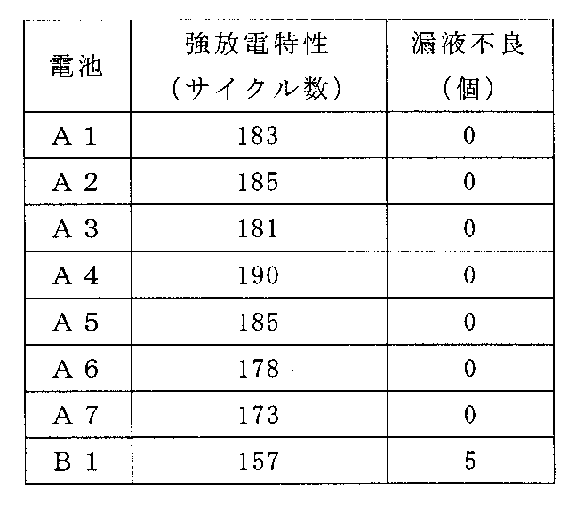
表4から明らかなように、比較例の炭素棒を用いた電池B1では、放電のサイクル数が157と少なく、100個中5個の電池について漏液不良が確認された。
これに対して、実施例の炭素棒を用いた電池A1~A7では、いずれも電池B1に比べてサイクル数が顕著に多くなった。これは、電池A1~A7では、電池B1に比べて、使用した炭素棒の電気抵抗が小さいことによるものと考えられる。特に、電池A1~A5では、約180サイクル以上の優れた強放電特性が得られた。中でも、電池A4では、サイクル数は約190サイクルであり、強放電特性が大幅に向上した。このような結果が得られたのは、電池A1~A7では、炭素棒の電気抵抗が小さく、乾電池の短絡電流が大きくなるので、その分大きな電流を取り出すことができたためと考えられる。
これに対して、実施例の炭素棒を用いた電池A1~A7では、いずれも電池B1に比べてサイクル数が顕著に多くなった。これは、電池A1~A7では、電池B1に比べて、使用した炭素棒の電気抵抗が小さいことによるものと考えられる。特に、電池A1~A5では、約180サイクル以上の優れた強放電特性が得られた。中でも、電池A4では、サイクル数は約190サイクルであり、強放電特性が大幅に向上した。このような結果が得られたのは、電池A1~A7では、炭素棒の電気抵抗が小さく、乾電池の短絡電流が大きくなるので、その分大きな電流を取り出すことができたためと考えられる。
また、電池A1~A7の各電池では、100個の試験電池のうち漏液不良となったものは1つも見られなかった。これは、これらの電池に使用した炭素棒では、メジアン細孔が小さく、大きなクラックも発生しないため、電解液に対する防水性が向上したためと考えられる。炭素棒の防水性が向上することにより、マンガン乾電池に組み込まれた場合に、炭素棒中への電解液の浸透が阻止され、正極端子板の腐食が抑制される。そのため、炭素棒を通じて電解液が乾電池の外部まで漏液して、使用機器に損傷を与えるのを有効に防止できる。
《実施例9~10および比較例2》
炭素質粉末、結着剤および半導体化促進剤を、表5に示す割合で配合する以外は、実施例1と同様にして、炭素棒を得、得られた炭素棒を用いて、パラフィンワックスを含む炭素棒を作製した。なお、比較例2については、比較例1と同様にして、パラフィンワックスを含む炭素棒を作製した。
得られたパラフィンワックスを含む炭素棒(単に炭素棒ともいう)について、実施例1と同様にして、電気抵抗を測定した。結果を表6に示す。
炭素質粉末、結着剤および半導体化促進剤を、表5に示す割合で配合する以外は、実施例1と同様にして、炭素棒を得、得られた炭素棒を用いて、パラフィンワックスを含む炭素棒を作製した。なお、比較例2については、比較例1と同様にして、パラフィンワックスを含む炭素棒を作製した。
得られたパラフィンワックスを含む炭素棒(単に炭素棒ともいう)について、実施例1と同様にして、電気抵抗を測定した。結果を表6に示す。
ただし、実施例では、結着剤として、土岐口蛙目粘土(浅岡窯業原料製)を用い、半導体化促進剤として、Nb2O5(三津和化学製)またはY2O3(日本イットリウム製)を用いた。使用した土岐口蛙目粘土は、珪酸塩鉱物Al2Si2O5(OH)4を74.0質量%含み、ケイ素原子を16.7質量%およびアルミニウム原子を15.6質量%含んでいた。
また、得られた炭素棒(パラフィンワックスを含まない炭素棒)中の、ケイ素原子含有量は4.1質量%であり、アルミニウム原子含有量は、3.9質量%であった。
また、得られた炭素棒(パラフィンワックスを含まない炭素棒)中の、ケイ素原子含有量は4.1質量%であり、アルミニウム原子含有量は、3.9質量%であった。
なお、表5中のNb2O5の配合比0.2質量%は、粘土の主成分である珪酸塩鉱物のケイ素原子に対してニオブ1.0原子%に相当し、同様に、Y2O3の配合比0.2質量%は、ケイ素原子に対してイットリウム1.2原子%に相当する。


表6から明らかなように、実施例9および10では、比較例2に比べて、電気抵抗が顕著に低くなっている。これは、実施例1と同様に、炭素質粉末同士の接触性が向上されたことに加え、さらに、半導体化促進剤を用いて焼成することにより、粘土が半導体化されたため、導電性が向上したものと考えられる。
《実施例11~14》
本実施例では、粘土に対する半導体化促進剤の割合を変化させた。
具体的には、粘土に含まれるケイ素原子に対する半導体化促進剤中のニオブ原子の配合比を、表7に示す値(原子%)に変更する以外は、実施例9と同様にして、パラフィンワックスを含む炭素棒を作製し、電気抵抗を測定した。結果を表7に示す。
なお、得られた炭素棒(パラフィンワックスを含まない炭素棒)中の、Si原子含有量は、4.1質量%であり、Al原子含有量は、3.9質量%であった。
本実施例では、粘土に対する半導体化促進剤の割合を変化させた。
具体的には、粘土に含まれるケイ素原子に対する半導体化促進剤中のニオブ原子の配合比を、表7に示す値(原子%)に変更する以外は、実施例9と同様にして、パラフィンワックスを含む炭素棒を作製し、電気抵抗を測定した。結果を表7に示す。
なお、得られた炭素棒(パラフィンワックスを含まない炭素棒)中の、Si原子含有量は、4.1質量%であり、Al原子含有量は、3.9質量%であった。

表7から明らかなように、実施例11~14の炭素棒は、いずれも、実施例9と同様に、低い電気抵抗を示した。このような結果が得られたのは、実施例9と同様の理由によるものと考えられる。
半導体化促進剤が効果的に作用し、所望の電気特性を得る観点からは、粘土に含まれるケイ素原子に対する半導体化促進剤の金属原子の配合比を、0.05~2原子%の範囲にするのが好ましい。
なお、実施例9~14では、粘土として、土岐口蛙目粘土を用い、半導体化促進剤として、Nb2O5またはY2O3を用いた例を示したが、他の粘土および/または他の半導体化促進剤を用いた場合にも、同様の効果が得られる。
《実施例15》
実施例9~14および比較例2で得られた炭素棒(パラフィンワックスを含む炭素棒)を用いる以外は、実施例8と同様にして、図1に示す単3形のマンガン乾電池を作製し、強放電特性を評価した。なお、実施例9~14の炭素棒を用いて得られた電池を、電池A9~A14とし、比較例2の炭素棒を用いて得られた電池を、電池B2とした。
結果を表8に示す。
実施例9~14および比較例2で得られた炭素棒(パラフィンワックスを含む炭素棒)を用いる以外は、実施例8と同様にして、図1に示す単3形のマンガン乾電池を作製し、強放電特性を評価した。なお、実施例9~14の炭素棒を用いて得られた電池を、電池A9~A14とし、比較例2の炭素棒を用いて得られた電池を、電池B2とした。
結果を表8に示す。

表8から明らかなように、実施例の炭素棒を用いた電池A9~A14では、180以上のサイクル数が得られ、比較例の炭素棒を用いた電池B2に比べて、優れた強放電特性が得られた。これは、電池A9~A14では、炭素棒の電気抵抗が顕著に小さいことにより、乾電池の短絡電流が大きくなるので、その分大きな電流を取り出すことができたことによるものと考えられる。
本発明を現時点での好ましい実施態様に関して説明したが、そのような開示を限定的に解釈してはならない。種々の変形および改変は、上記開示を読むことによって本発明に属する技術分野における当業者には間違いなく明らかになるであろう。したがって、添付の請求の範囲は、本発明の真の精神および範囲から逸脱することなく、すべての変形および改変を包含する、と解釈されるべきものである。
本発明の炭素棒は、マンガン乾電池の正極集電体に使用するのに適している。また、炭素棒を用いたマンガン乾電池は、携帯機器、情報機器などの各種電子機器類の電源に好適に使用される。
1 正極合剤
2 炭素棒
3 セパレータ
4 負極缶
5 ガスケット
6 負極端子板
7 シールリング
8 樹脂チューブ
9 鍔紙
10 金属外装缶
11 正極端子板
12 絶縁リング
13 底紙
2 炭素棒
3 セパレータ
4 負極缶
5 ガスケット
6 負極端子板
7 シールリング
8 樹脂チューブ
9 鍔紙
10 金属外装缶
11 正極端子板
12 絶縁リング
13 底紙
Claims (15)
- 導電性の炭素質粉末と、前記炭素質粉末を結合させる粘土の焼結体とを含み、細孔を有する炭素棒。
- 前記粘土が珪酸塩鉱物を主成分として含む、請求項1に記載の炭素棒。
- 前記珪酸塩鉱物が、カオリナイト系、ディッカイト系、ナクライト系、ハロイサイト系、セリサイト系およびモンモリロナイト系の粘土鉱物からなる群より選択される少なくとも一種である、請求項2に記載の炭素棒。
- 前記珪酸塩鉱物が、アルミニウムを含み、
炭素棒中のケイ素の含有量が1~13質量%であり、アルミニウムの含有量が0.7~9.5質量%である、請求項2または3に記載の炭素棒。 - メジアン細孔径が0.4μm以下である、請求項1~4のいずれか1項に記載の炭素棒。
- 前記粘土の焼結体が半導体化されている、請求項1~5のいずれか1項に記載の炭素棒。
- 前記半導体化された粘土の焼結体が、Y、La、Ce、Nd、Dy、V、Nb、Ta、WおよびMnからなる群より選択される少なくとも一種を含む、請求項6に記載の炭素棒。
- さらに、前記細孔に含浸されたパラフィンワックスを含む、請求項1~7のいずれか1項に記載の炭素棒。
- (1)導電性の炭素質粉末、粘土および水を含む混合物を得る工程と、
(2)前記混合物を圧縮成形して、棒状の成形体を得る工程と、
(3)前記成形体を焼成し、前記炭素質粉末を結合させるように、前記粘土を焼結させて前記炭素棒を得る工程と、を含む炭素棒の製造方法。 - 前記混合物が、前記粘土1質量部に対して、前記炭素質粉末を0.7~19質量部含み、前記粘土および炭素質粉末の合計100質量部に対して水を10~30質量部含む請求項9に記載の炭素棒の製造方法。
- 前記混合物が、さらに、前記粘土の半導体化を促進するための半導体化促進剤を含む、請求項9または10に記載の炭素棒の製造方法。
- 前記粘土が珪酸塩鉱物を主成分として含み、
前記半導体化促進剤が、金属酸化物であり、
前記混合物が、前記珪酸塩鉱物のケイ素原子に対して、前記金属酸化物の金属元素が0.05~2原子%となる含有量で、前記半導体化促進剤を含む、請求項11に記載の炭素棒の製造方法。 - 前記半導体化促進剤が、Y2O3、La2O3、CeO2、Nd2O5、Dy2O3、V2O5、Nb2O5、Ta2O5、W2O5およびMnO2からなる群より選択される少なくとも一種である、請求項11または12に記載の炭素棒の製造方法。
- 前記工程(3)において、前記焼成が、非酸化性雰囲気下、800~1500℃の温度で行われる、請求項13に記載の炭素棒の製造方法。
- 二酸化マンガンを含む円筒形の正極合剤と、
亜鉛を含む負極缶と、
前記正極合剤と前記負極缶との間に配されたセパレータと、
前記正極合剤に挿入された請求項1~8のいずれか1項に記載の炭素棒と、
電解液とを備えるマンガン乾電池。
Priority Applications (1)
| Application Number | Priority Date | Filing Date | Title |
|---|---|---|---|
| CN2012800044333A CN103282328A (zh) | 2011-03-04 | 2012-02-27 | 碳棒及其制造方法以及锰干电池 |
Applications Claiming Priority (4)
| Application Number | Priority Date | Filing Date | Title |
|---|---|---|---|
| JP2011-047338 | 2011-03-04 | ||
| JP2011047338A JP2014097897A (ja) | 2011-03-04 | 2011-03-04 | 炭素棒およびマンガン乾電池 |
| JP2011274184A JP2014097898A (ja) | 2011-12-15 | 2011-12-15 | 炭素棒およびマンガン乾電池 |
| JP2011-274184 | 2011-12-15 |
Publications (1)
| Publication Number | Publication Date |
|---|---|
| WO2012120825A1 true WO2012120825A1 (ja) | 2012-09-13 |
Family
ID=46797800
Family Applications (1)
| Application Number | Title | Priority Date | Filing Date |
|---|---|---|---|
| PCT/JP2012/001321 WO2012120825A1 (ja) | 2011-03-04 | 2012-02-27 | 炭素棒およびその製造方法、ならびにマンガン乾電池 |
Country Status (2)
| Country | Link |
|---|---|
| CN (1) | CN103282328A (ja) |
| WO (1) | WO2012120825A1 (ja) |
Cited By (1)
| Publication number | Priority date | Publication date | Assignee | Title |
|---|---|---|---|---|
| WO2023095744A1 (ja) * | 2021-11-29 | 2023-06-01 | 三菱鉛筆株式会社 | 電池用炭素集電体 |
Families Citing this family (2)
| Publication number | Priority date | Publication date | Assignee | Title |
|---|---|---|---|---|
| CN115448288B (zh) * | 2022-10-20 | 2024-03-01 | 温州赛普克电子科技有限公司 | 一种碳棒电极和制备方法及其应用 |
| CN116443845A (zh) * | 2023-03-09 | 2023-07-18 | 河南克能新能源科技有限公司 | 一种低成本钠离子电池负极材料的制备方法及其电池 |
Citations (2)
| Publication number | Priority date | Publication date | Assignee | Title |
|---|---|---|---|---|
| JPS5144115B1 (ja) * | 1966-04-05 | 1976-11-26 | ||
| JPS6355147A (ja) * | 1986-08-23 | 1988-03-09 | 山本 隆一 | 炭素と粘土を原料として得られる導電体 |
Family Cites Families (2)
| Publication number | Priority date | Publication date | Assignee | Title |
|---|---|---|---|---|
| JPS5144115A (en) * | 1974-10-02 | 1976-04-15 | Mitsubishi Cement Asbestos | Yanezaino seizohoho |
| JP2005026151A (ja) * | 2003-07-04 | 2005-01-27 | Matsushita Electric Ind Co Ltd | マンガン乾電池用正極集電体およびそれを用いたマンガン乾電池 |
-
2012
- 2012-02-27 CN CN2012800044333A patent/CN103282328A/zh active Pending
- 2012-02-27 WO PCT/JP2012/001321 patent/WO2012120825A1/ja active Application Filing
Patent Citations (2)
| Publication number | Priority date | Publication date | Assignee | Title |
|---|---|---|---|---|
| JPS5144115B1 (ja) * | 1966-04-05 | 1976-11-26 | ||
| JPS6355147A (ja) * | 1986-08-23 | 1988-03-09 | 山本 隆一 | 炭素と粘土を原料として得られる導電体 |
Non-Patent Citations (1)
| Title |
|---|
| SAISHIN DENCHI HANDBOOK, 20 December 1996 (1996-12-20), pages 96 * |
Cited By (1)
| Publication number | Priority date | Publication date | Assignee | Title |
|---|---|---|---|---|
| WO2023095744A1 (ja) * | 2021-11-29 | 2023-06-01 | 三菱鉛筆株式会社 | 電池用炭素集電体 |
Also Published As
| Publication number | Publication date |
|---|---|
| CN103282328A (zh) | 2013-09-04 |
Similar Documents
| Publication | Publication Date | Title |
|---|---|---|
| Yang et al. | Ultrasmall MnO@ N-rich carbon nanosheets for high-power asymmetric supercapacitors | |
| Zhou et al. | Wet milled synthesis of an Sb/MWCNT nanocomposite for improved sodium storage | |
| KR102079301B1 (ko) | 납산 배터리를 위한 산화된 카본 블랙 및 적용 | |
| RU2395477C2 (ru) | Спеченный огнеупорный блок на основе карбида кремния со связкой из нитрида кремния | |
| CN105390673B (zh) | 一种锂离子电池高容量低反弹石墨负极材料的制备方法 | |
| JP2011512000A5 (ja) | ||
| MX2010009700A (es) | Bateria de litio-azufre y catodo para la misma. | |
| JP4434727B2 (ja) | 改良カソードを有するアルカリ電池 | |
| US20210111400A1 (en) | Cathodes for solid-state lithium sulfur batteries and methods of manufacturing thereof | |
| WO2012120825A1 (ja) | 炭素棒およびその製造方法、ならびにマンガン乾電池 | |
| JPS5826464A (ja) | 電池およびその製法 | |
| Ding et al. | Fe2Mo3O8/MoO2@ C composites with pseudocapacitive properties and fast diffusion kinetics for the anode of Lithium-Ion batteries | |
| KR20210094075A (ko) | 개선된 저온 성능을 갖는 조성물, 전극 및 납산 배터리 | |
| Lou et al. | Achieving highly stable Li–O 2 battery operation by designing a carbon nitride-based cathode towards a stable reaction interface | |
| US3427203A (en) | Large surface area electrodes and a method for preparing them | |
| JP2010192257A (ja) | 鉛蓄電池および鉛蓄電池用ペースト式負極板の製造方法 | |
| CN105655003B (zh) | 一种改性电极糊及其制备方法 | |
| CN113185297B (zh) | 电加热用陶瓷材料及其应用 | |
| KR101833972B1 (ko) | 이차 전지용 흑연재의 제조 방법 | |
| JP7010556B2 (ja) | 正極板及び鉛蓄電池 | |
| JP2014097897A (ja) | 炭素棒およびマンガン乾電池 | |
| JP5481560B2 (ja) | 非水電解液二次電池 | |
| WO2011052118A1 (ja) | 集電体およびその製造方法、ならびにマンガン乾電池 | |
| JP5300331B2 (ja) | リチウム電池用正極合剤成形体及びリチウム電池 | |
| JP2014097898A (ja) | 炭素棒およびマンガン乾電池 |
Legal Events
| Date | Code | Title | Description |
|---|---|---|---|
| 121 | Ep: the epo has been informed by wipo that ep was designated in this application |
Ref document number: 12754578 Country of ref document: EP Kind code of ref document: A1 |
|
| NENP | Non-entry into the national phase |
Ref country code: DE |
|
| 122 | Ep: pct application non-entry in european phase |
Ref document number: 12754578 Country of ref document: EP Kind code of ref document: A1 |
|
| NENP | Non-entry into the national phase |
Ref country code: JP |