WO2012120728A1 - 電子顕微鏡用試料ホルダーおよび試料観察方法 - Google Patents
電子顕微鏡用試料ホルダーおよび試料観察方法 Download PDFInfo
- Publication number
- WO2012120728A1 WO2012120728A1 PCT/JP2011/075334 JP2011075334W WO2012120728A1 WO 2012120728 A1 WO2012120728 A1 WO 2012120728A1 JP 2011075334 W JP2011075334 W JP 2011075334W WO 2012120728 A1 WO2012120728 A1 WO 2012120728A1
- Authority
- WO
- WIPO (PCT)
- Prior art keywords
- sample
- electron microscope
- sample holder
- container
- holder
- Prior art date
- Legal status (The legal status is an assumption and is not a legal conclusion. Google has not performed a legal analysis and makes no representation as to the accuracy of the status listed.)
- Ceased
Links
Images





Classifications
-
- H—ELECTRICITY
- H01—ELECTRIC ELEMENTS
- H01J—ELECTRIC DISCHARGE TUBES OR DISCHARGE LAMPS
- H01J37/00—Discharge tubes with provision for introducing objects or material to be exposed to the discharge, e.g. for the purpose of examination or processing thereof
- H01J37/02—Details
- H01J37/20—Means for supporting or positioning the object or the material; Means for adjusting diaphragms or lenses associated with the support
-
- G—PHYSICS
- G01—MEASURING; TESTING
- G01N—INVESTIGATING OR ANALYSING MATERIALS BY DETERMINING THEIR CHEMICAL OR PHYSICAL PROPERTIES
- G01N1/00—Sampling; Preparing specimens for investigation
- G01N1/28—Preparing specimens for investigation including physical details of (bio-)chemical methods covered elsewhere, e.g. G01N33/50, C12Q
-
- H—ELECTRICITY
- H01—ELECTRIC ELEMENTS
- H01J—ELECTRIC DISCHARGE TUBES OR DISCHARGE LAMPS
- H01J37/00—Discharge tubes with provision for introducing objects or material to be exposed to the discharge, e.g. for the purpose of examination or processing thereof
- H01J37/02—Details
- H01J37/16—Vessels; Containers
-
- H—ELECTRICITY
- H01—ELECTRIC ELEMENTS
- H01J—ELECTRIC DISCHARGE TUBES OR DISCHARGE LAMPS
- H01J37/00—Discharge tubes with provision for introducing objects or material to be exposed to the discharge, e.g. for the purpose of examination or processing thereof
- H01J37/02—Details
- H01J37/18—Vacuum locks ; Means for obtaining or maintaining the desired pressure within the vessel
-
- H—ELECTRICITY
- H01—ELECTRIC ELEMENTS
- H01J—ELECTRIC DISCHARGE TUBES OR DISCHARGE LAMPS
- H01J37/00—Discharge tubes with provision for introducing objects or material to be exposed to the discharge, e.g. for the purpose of examination or processing thereof
- H01J37/26—Electron or ion microscopes; Electron or ion diffraction tubes
- H01J37/28—Electron or ion microscopes; Electron or ion diffraction tubes with scanning beams
-
- H—ELECTRICITY
- H01—ELECTRIC ELEMENTS
- H01J—ELECTRIC DISCHARGE TUBES OR DISCHARGE LAMPS
- H01J2237/00—Discharge tubes exposing object to beam, e.g. for analysis treatment, etching, imaging
- H01J2237/20—Positioning, supporting, modifying or maintaining the physical state of objects being observed or treated
- H01J2237/2001—Maintaining constant desired temperature
-
- H—ELECTRICITY
- H01—ELECTRIC ELEMENTS
- H01J—ELECTRIC DISCHARGE TUBES OR DISCHARGE LAMPS
- H01J2237/00—Discharge tubes exposing object to beam, e.g. for analysis treatment, etching, imaging
- H01J2237/20—Positioning, supporting, modifying or maintaining the physical state of objects being observed or treated
- H01J2237/2002—Controlling environment of sample
- H01J2237/2003—Environmental cells
Definitions
- the present invention relates to a charged particle beam apparatus, and relates to a local low-vacuum technique for maintaining only the vicinity of a sample in a low-vacuum atmosphere in an electron microscope in which an electron beam emitted from an electron gun is focused on the sample and irradiated onto the sample.
- a charged particle beam device that irradiates a sample with charged particles as a probe, detects secondary particles generated from the sample or accompanying charged particles, and obtains information on the probe irradiation position from the detected signal intensity.
- a scanning electron microscope SEM: Scanning Electron Microscope
- SIM scanning ion microscope
- FIB focused ion beam
- the sample is generally placed in a sample chamber maintained in a high vacuum atmosphere of 10 ⁇ 2 Pa or more in order to remove a gas atmosphere that hinders the probe.
- the sample When a non-conductive sample is observed in the above charged particle beam apparatus, the sample is charged by the irradiated charged particle beam. Due to the influence of the sample charging, the primary charged particle beam is bent, and the information on the surface state of the sample cannot be obtained correctly due to the drift of the irradiation region, abnormal charging contrast, and the like.
- the sample chamber is placed in a low vacuum state of several Pa to several thousand Pa, and the sample charging is neutralized by charged particles and ions generated by collision of secondary electrons with gas molecules.
- the sample charging is neutralized by charged particles and ions generated by collision of secondary electrons with gas molecules.
- Patent Document 1 As another method for avoiding this, as described in Patent Document 1, a nozzle for gas blowing is provided, and a gas is blown directly onto the sample from an external gas source so that only the region immediately above the sample is subjected to low vacuum. A method for realizing the above has been proposed.
- the environmental control type electron beam apparatus having a multistage differential exhaust system
- good quality images cannot be obtained due to the influence of the scattering of the probe.
- a cooling stage is placed on the environmental control type electron beam apparatus, and the sample is cooled to around 0 ° C., so that the saturated water vapor pressure is lowered to about several hundred Pa and observed. There are methods.
- the charging of the sample causes abnormal conton last and probe charged particle beam drift.
- a method for removing this there is a method of blowing a gas locally to the irradiation position of the probe charged particle beam of the sample.
- Either a method of lowering the vacuum in the entire sample chamber or a method of blowing gas to the vicinity of the sample Either a charged particle beam device is modified or a mechanism for transporting gas from an external gas source into the sample chamber, a mechanism for adjusting the gas flow rate, Addition of a medium-scale system such as a mechanism for moving the nozzle is required.
- An object of the present invention is to provide a charged particle beam apparatus, a sample holder, and a sample observation method capable of lowering the vacuum only in the vicinity of a sample and cooling the sample by a simpler technique than before.
- a sample to be observed is placed on a sample holder that includes a container that can contain a substance that serves as a gas source, a lid member that covers the container in a vacuum-sealed state, and a sample stage that includes a through hole. Then, a gas that evaporates or volatilizes from the container through the through-hole is supplied to the sample to be observed, so that a local low vacuum state is formed at the mounting position of the sample to be observed or in the vicinity of the sample. To do. An electron beam is irradiated on the sample in the low vacuum atmosphere formed in this way, and an image of the sample to be observed is obtained.
- the present invention only the vicinity of the sample is made a low vacuum region and the sample can be cooled more easily than in the past.
- FIG. 1 is an overall configuration diagram of a charged particle beam apparatus according to Embodiment 1.
- FIG. It is a whole block diagram of a sample holder. It is a top view of a lid member. It is sectional drawing of a cover member. It is a cross-sectional enlarged view of the recessed part provided in the cover member. It is a figure which shows the structural example of the aperture_diaphragm
- FIG. 1 is an overall configuration diagram of the scanning electron microscope of the present embodiment.
- the scanning electron microscope 1 roughly includes an electron gun chamber 2 installed at the top, a focusing lens chamber 3 installed below it, an objective lens chamber 4 installed below it, and a sample chamber 5 installed below it.
- An electron source 6 is installed in the electron gun chamber 2
- a focusing lens 7 is installed in the focusing lens chamber 3
- an objective lens 8 is installed in the objective lens chamber 4.
- a secondary electron detector 20 for taking in secondary electrons generated from the sample is installed in the objective lens chamber 4.
- a XYTZR drive mechanism that is, a sample fine movement device 9 having an XY stage, an inclined stage (T stage), a height stage (Z stage) and a rotary stage (R stage) is installed.
- An exchange chamber 10 is installed, and samples and the like can be taken in and out from the sample chamber 5 without opening the sample chamber to the atmosphere.
- Each chamber is connected to a vacuum pump (for example, ion pumps 11 and 12, turbo molecular pump 13 and rotary pump 14) constituting an exhaust system, and each sample chamber has a pressure higher than atmospheric pressure such as ultra-high vacuum or high vacuum. Can be kept low.
- a sample holder 17 filled with a gas source 18 (for example, water) is placed on the sample fine movement device 9.
- a gas source 18 for example, water
- water vapor contains oxygen it is also effective for removing contamination on the sample.
- the pressure inside the sample holder 17 is also lowered by the pressure in the sample chamber 5 drawn by the turbo molecular pump. When the pressure reaches about 2000 Pa, water becomes water vapor and is ejected from a through hole provided in the sample holder 17.
- a material that easily volatilizes and sublimates such as a material in which an arbitrary gas is adsorbed, may be used in addition to water.
- a flow path for guiding the gas ejected from the through-hole to the sample is formed inside the sample holder 17, and a local low vacuum state can be formed in the vicinity of the sample 19 (that is, the pressure in the vicinity of the sample is set to the sample). It can be higher than the pressure inside the room). As a result, an image in which sample charging is suppressed can be acquired.
- the low-vacuum pressure formed in the vicinity of the sample can be varied from several Pa to 2000 Pa by changing the diameter of the through hole.
- the sample exchange chamber 10 and the sample exchange rod 22 are mechanisms for taking the sample holder 17 into and out of the sample chamber 5 without opening the sample chamber 5 to the atmosphere.
- the sample exchange chamber 10 is connected to the rotary pump 14. Piping is connected.
- the piping of the sample exchange chamber 10 is provided with a valve 15, and only the sample exchange chamber can be brought to atmospheric pressure by opening the valve 15.
- the sample holder 17 includes an attachment 33 in addition to the main body. By using the sample exchange chamber 10 and the sample exchange rod 22, the sample holder 17 can be exchanged without opening the sample chamber 5 to the atmosphere. is there.
- the sample is moved by the sample fine movement device 9 so that the attachment 33 is at the same height as the moving axis of the sample exchange rod 22 (the dashed line in the figure). Adjust the height of the holder 17.
- the sample exchange rod 22 is moved to the right side of the page, and the attachment 33 is gripped.
- the sample holder 17 is moved to the sample exchange chamber 10 side using the XY stage, and finally pulled into the sample exchange chamber 10 by the sample exchange rod 22.
- the gate valve 21 is closed, the valve 15 is opened, and the sample exchange chamber 10 is opened to the atmosphere.
- the valve 16 on the pipe connecting the turbo molecular pump 13 and the rotary pump 14 is closed.
- the sample holder 17 of the present embodiment is roughly composed of a container 30 and a cap (lid member) 40, and the container portion and the sample placement portion can be separated. This is because the gas source 18 can be repeatedly filled and the inside of the container 30 can be cleaned.
- the container 30 and the cap 40 of the present embodiment have a short columnar shape, and each includes an outer periphery of the cap fitting part 49 and a fitting part 34 of the container provided with fitting parts 49 and 34 for fitting together.
- a thread groove 31 is formed on the inner wall surface of the, and the cap can be removed from the container 30 by turning the cap 40.
- the container 30 is provided with an O-ring 32 as a vacuum seal member when the cap 40 is attached so that the gas source 18 is filled therein.
- FIG. 3A to 3C show the detailed structure of the cap 40.
- FIG. 3A is a plan view of the cap 40
- FIG. 3B is a cross-sectional view of the cap 40
- FIG. 3C is an enlarged cross-sectional view of a recess provided in the cap 40.
- a concave portion is provided in the central portion of the cap 40.
- the concave portion is an installation portion of the sample 19 and has a gas supply function for supplying the gas rising from the container 30 to the sample.
- a through hole 41 through which the gas rising from the container 30 passes is formed on the bottom surface of the recess, and a sample stage 45 is installed above the through hole 41.
- Four holes 47 communicating with the through hole 41 are opened at the outer periphery of the sample stage 45 so as to surround the sample 19, and the gas rising through the through hole 41 passes through the hole 47.
- An annular throttle member 42 for limiting the flow rate of the gas supplied from the through hole 41 is installed between the sample stage 45 and the through hole 41.
- the aperture member 42 has a hole, and the diameter of the hole is practically in the range of several ⁇ m to several mm.
- a diaphragm retainer 43 that fixes the diaphragm member 42 is provided above the diaphragm member 42.
- a hole 46 is also formed in the central portion of the diaphragm retainer 43 so that the gas that has passed through the diaphragm member 42 can pass therethrough.
- the diameter of the through hole 41 may be changed without using the throttle member 42.
- the diameter of the through hole 41 is determined once the cap is manufactured, it is necessary to prepare a plurality of caps 40 having through holes with different hole diameters when adjusting the gas flow rate. Therefore, in principle, the throttle member 42 may be omitted, but it is better that the gas flow rate can be easily controlled.
- the gas flow rate can be easily adjusted.
- a screw groove 44 female screw
- screw grooves male threads
- the elevating mechanism in the sample stage 45 also serves as a height adjustment function for the sample 19, so that the top of the sample 19 is always set to the same height as the upper surface of the cap 40 even when the sample is replaced with a different sample. it can.
- a plurality of holes (or depressions) different from the hole 46 are formed on the outer periphery of the diaphragm retainer 43, and an appropriate jig such as tweezers is fitted into the hole and rotated along the screw groove to thereby reduce the diaphragm.
- the presser 43 is configured to be removable. Since a plurality of holes 47 are originally opened in the sample stage 45 as shown in FIG. A, these holes 47 can be used when removing the sample stage 45 from the recess.
- an elevating mechanism other than the thread groove can be used, but as the elevating mechanism of the sample stage 45 and the diaphragm holder 43, the method using the thread groove as described above is the simplest.
- the diameter of the aperture member 42 is configured to be fitted in the recess, and a thread is cut on the side surface of the aperture member 42, the aperture holder 43 is not necessary.
- a flow path such as the gas path 48 shown in FIGS. 3B and 3C is formed, and the gas flows into the vicinity of the sample.
- the vicinity of the sample can be efficiently made a low vacuum with a minimum amount of gas without supplying gas from the outside.
- Example 2 In the present embodiment, a configuration for making the vicinity of the sample 19 a low vacuum more effectively is shown.
- the upper lid 50 (second lid member) is attached to the upper portion of the cap 40 shown in FIGS. 3A, 3B, and 3C using screws or the like.
- the upper lid 50 is provided with a central hole 51 having a diameter smaller than that of the concave portion or the sample stage 45 so that the gas rising from the lower part of the sample 19 is throttled at the upper part of the sample 19. For this reason, since the sample 19 is installed in the flow path as shown in the gas path 52, the degree of vacuum in the vicinity of the sample becomes lower when compared with the same gas flow rate as in Example 1.
- the upper lid 50 also serves as a diaphragm, the degree of vacuum in the lower chamber of the upper lid 50 can be kept low, and the gas flowing into the sample chamber 5 is reduced. Deterioration of the degree of vacuum of the sample chamber 5 can be reduced.
- FIG. 6 shows a modification of the cap 40.
- the gas is not applied from the lower part of the sample 19, but the sample is in the gas injection direction by providing the through hole 61 on the side surface of the sample 19, and the position of the gas passage hole on the sample mounting surface of the sample stage 45
- This is effective when gas cannot be emitted from the lower part, such as a large sample that spreads outside and is placed.
- further lowering of the vacuum can be expected by directing the spray gas directly on the sample, that is, on the observation surface. Note that by covering the upper lid 50 shown in FIG. 5 on the cap 60 shown in FIG. 6, there is an effect that the above-described large sample can be observed in a lower vacuum state.
Landscapes
- Chemical & Material Sciences (AREA)
- Analytical Chemistry (AREA)
- Physics & Mathematics (AREA)
- Health & Medical Sciences (AREA)
- Life Sciences & Earth Sciences (AREA)
- Biochemistry (AREA)
- General Health & Medical Sciences (AREA)
- General Physics & Mathematics (AREA)
- Immunology (AREA)
- Pathology (AREA)
- Analysing Materials By The Use Of Radiation (AREA)
- Sampling And Sample Adjustment (AREA)
Abstract
試料近傍の局所低真空化と試料冷却を環境制御型電子線装置ではない通常の電子線装置でも実現し、かつ装置に改造およびボンベ等の設備を追加することなく、試料ホルダーのみで実現する。ガス源となる物質を内部に収納可能な容器と当該容器の試料台下部に貫通孔を備えた試料ホルダーに被観察試料を載置し、上記貫通孔を介して前記容器から蒸発あるいは揮発してくるガスを上記被観察試料に供給することにより、上記被観察試料の載置位置あるいは試料の近傍に局所的な低真空状態を形成する。さらに揮発するときの気化熱を利用して試料冷却も可能となる。
Description
本発明は荷電粒子線装置に係り、電子銃より放出された電子線が試料上で集束されて試料に照射される電子顕微鏡において、試料近傍のみを低真空雰囲気に保つ局所低真空技術に関する。
荷電粒子をプローブとして試料上に照射し、それに伴って試料より発生する二次粒子、もしくは透過した荷電粒子を検出し、検出された信号強度からプローブ照射位置に関する情報を得る荷電粒子線装置は、例えば電子をプローブとする走査電子顕微鏡(SEM:Scanning Electron Microscope)やイオンをプローブとする走査イオン顕微鏡(SIM:Scanning Ion Microscope)や収束イオンビーム(FIB:Focused Ion Beam)装置またはそれらを組み合わせた装置が数多く提示されている。
このような荷電粒子線装置では、一般に、プローブの妨げとなるガス雰囲気を除去するため、試料は10-2Pa以上の高真空雰囲気に保たれた試料室内に配置される。
前述荷電粒子線装置において導電性を持たない試料を観察すると、照射される荷電粒子線によって試料が帯電する。この試料帯電の影響によって、一次荷電粒子線が曲げられ照射領域のドリフト,異常な帯電コントラストなどから試料の表面状態の情報が正しく得られない。
試料帯電を防ぐ手段の一つとして、試料室を数Pa~数千Pa程度の低真空状態にして、荷電粒子線および二次電子と気体分子の衝突により発生したイオンによって試料帯電を中和するなどの手段があり、環境制御型電子線装置として実用化されている。
しかし、試料室を低真空状態にしても荷電粒子源のある電子銃内部を超高真空(約10-8Pa)に保つ必要があり、多段の差動排気を持つ排気システムが必要である。また、試料室全体がほぼ均一な低真空であるため、荷電粒子線が低真空領域を通過する距離が長くなる。このため、多くの気体分子との衝突によって対物レンズによって集束されたプローブが散乱され分解能の劣化やX線分析などの空間分解能の劣化が生ずる。
これを回避するための別の手法としては、特許文献1に記載のように、ガス吹き付け用のノズルを設け、外部のガス源から試料直上にガスを吹き付けることで試料直上の領域のみを低真空化する手法が提案されている。
多段差動排気システムを持つ環境制御型電子線装置においてもプローブの散乱を抑えることは分解能を向上させる上で重要である。特に、含水試料をそのままの状態で観察する場合、水分の蒸発を抑えるため試料室内の圧力を約2000Paの飽和水蒸気圧付近まで高める必要がある。しかし、プローブの散乱の影響により良質な画像を得ることは出来ない。これを回避するための別の手法としては、上記環境制御型電子線装置に冷却ステージを載置して試料を0℃付近まで冷却させることで飽和水蒸気圧を約数百Paまで下げて観察する方法などがある。
SEMなどの試料表面の微細構造を観察するための荷電粒子線装置において、試料の帯電は異常コントンラストや、プローブ荷電粒子線のドリフトなどの原因となる。これを除去するための方法として、局所的に試料のプローブ荷電粒子線の照射位置にガスを吹き付ける手法がある。
効果的に試料の帯電を除去するためには、試料近傍をできるだけ低真空状態にすることが望ましく、試料とガスが吹き出るノズル先端との距離を縮めなくてはならない。このことから、試料微動装置によって試料を任意の方向に移動させる場合、誤ってノズルと試料が衝突してしまう危険性が生じる。また、Z方向に移動する場合は、試料の移動に伴ってノズル位置も変えなくてはならない。
試料室内全体を低真空にする方法およびガスを試料近傍に吹き付ける方法いずれの方法も荷電粒子線装置に改造または、外部のガス源からガスを試料室内に運ぶ機構,ガスの流量調節を行う機構,ノズルを移動させる機構など中規模なシステムの追加が必要になる。
含水試料をそのままの状態で観察する場合、環境制御型電子線装置と冷却ステージを用いて、試料の乾燥を抑えることが出来るが、試料冷却を行っても試料室圧力を数百Paに保つ必要があるため、プローブの散乱の影響を取り除くことは出来ない。さらに、試料冷却は、ペルチェ素子や冷却水の循環などで行うことから中規模なシステムの追加が必要なり、荷電粒子線装置本来の操作性を損なうことが多い。
本発明の目的は、従来よりも簡便な手法で試料近傍のみを低真空にすると共に試料冷却をすることが可能な荷電粒子線装置,試料ホルダーおよび試料の観察方法を提供することにある。
本発明では、ガス源となる物質を内部に収納可能な容器と当該容器に真空シールされた状態でかぶせる蓋部材と、貫通孔を備えた試料台とを備える試料ホルダーに被観察試料を載置し、上記貫通孔を介して前記容器から蒸発あるいは揮発してくるガスを上記被観察試料に供給することにより、上記被観察試料の載置位置あるいは試料の近傍に局所的な低真空状態を形成する。このように形成された低真空雰囲気下の試料に電子線を照射し、被観察試料の画像を得る。
本発明によれば、従来よりも簡便に試料近傍のみを低真空領域にすると共に試料冷却を可能にする。
以下、図面を参照し、荷電粒子線装置の例として走査型電子顕微鏡(SEM)に対して本発明を適用した実施例について詳細に説明する。
(実施例1)
図1は本実施例の走査電子顕微鏡の全体構成図である。走査電子顕微鏡1は、大まかには、頂部に設置した電子銃室2と、その下方に設置した集束レンズ室3と、その下方に設置した対物レンズ室4と、その下方に設置した試料室5とより構成され、前記電子銃室2内には電子源6が設置され、集束レンズ室3内には集束レンズ7が設置され、対物レンズ室4内には対物レンズ8が設置されている。また、対物レンズ室4内には試料から発生した2次電子を取り込むための2次電子検出器20が設置されている。
図1は本実施例の走査電子顕微鏡の全体構成図である。走査電子顕微鏡1は、大まかには、頂部に設置した電子銃室2と、その下方に設置した集束レンズ室3と、その下方に設置した対物レンズ室4と、その下方に設置した試料室5とより構成され、前記電子銃室2内には電子源6が設置され、集束レンズ室3内には集束レンズ7が設置され、対物レンズ室4内には対物レンズ8が設置されている。また、対物レンズ室4内には試料から発生した2次電子を取り込むための2次電子検出器20が設置されている。
試料室5内にはXYTZRの駆動機構、すなわちXYステージ,傾斜ステージ(Tステージ),高さステージ(Zステージ)および回転ステージ(Rステージ)を持っている試料微動装置9が設置され、また試料交換室10が設置され試料室5から試料室を大気開放することなく試料等を出し入れできる。各部屋は、排気系を構成する真空ポンプ(例えば、イオンポンプ11,12,ターボ分子ポンプ13,ロータリーポンプ14)に接続され、各試料室内を超高真空あるいは高真空といった大気圧よりも圧力の低い状態に保持できる。
試料微動装置9の上には内部にガス源18(例えば水)を充填した試料ホルダー17が載置されている。水の場合は、室温では、約2000Paで蒸発し水蒸気となる。さらに水蒸気は酸素を含んでいることから試料上のコンタミネーションを除去するためにも効果的である。ターボ分子ポンプで引かれている試料室5の圧力よって試料ホルダー17内部の圧力も低下し、約2000Paになると水が水蒸気となって試料ホルダー17に設けられた貫通孔から噴出する。ガス源18となる物質としては、水の他、任意のガスを吸着させた材料といった揮発・昇華しやすい材料を使用しても良い。
試料ホルダー17の内部には貫通孔から噴出するガスを試料に導くための流路が形成されており、試料19の近傍に局所的な低真空状態を形成できる(すなわち、試料近傍の圧力を試料室内部の圧力に比べて高くできる)。これにより試料帯電が抑制された画像を取得できる。試料近傍に形成される低真空状態の圧力は、貫通孔の径を変えることによって試料近傍の圧力は数Pa~2000Pa程度に可変にすることができる。
試料交換室10および試料交換棒22は、試料室5内を大気開放せずに試料ホルダー17を試料室5内に出し入れするための機構であり、試料交換室10には、ロータリーポンプ14とつなぐ配管が接続されている。試料交換室10の配管にはバルブ15が設けられており、バルブ15を開放することにより試料交換室のみを大気圧にすることができる。
試料ホルダー17は、本体に加えてアタッチメント33を備えており、試料交換室10および試料交換棒22を用いることにより、試料室5内を大気開放せずに試料ホルダー17を交換することが可能である。
試料交換棒22を用いて試料ホルダー17を交換する場合には、まず、試料微動装置9によりアタッチメント33が試料交換棒22の移動軸(図中の一点鎖線)と同じ高さになるように試料ホルダー17の高さを調整する。次に、試料交換棒22を紙面右側に移動して、アタッチメント33を把持する。その後、XYステージを用いて試料ホルダー17を試料交換室10側に移動し、最終的に試料交換棒22で試料交換室10内に引き入れる。その後、ゲートバルブ21を閉じて、バルブ15を開放し、試料交換室10を大気開放する。この際、ターボ分子ポンプ13とロータリーポンプ14を結ぶ配管上のバルブ16は閉じておく。
次に試料ホルダー17の構造について図2,図3および図4を用いて説明する。
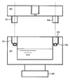
図2に示すように、本実施例の試料ホルダー17は、大きく分けて容器30とキャップ(蓋部材)40により構成されており、容器部と試料の載置部が分離できる。これは、ガス源18を繰り返し充填できるようにするためと、容器30内部をクリーニングできるようにするためである。
図2に示すように、本実施例の試料ホルダー17は、大きく分けて容器30とキャップ(蓋部材)40により構成されており、容器部と試料の載置部が分離できる。これは、ガス源18を繰り返し充填できるようにするためと、容器30内部をクリーニングできるようにするためである。
本実施例の容器30およびキャップ40は、丈の短い円柱形状を有し、それぞれ、互いに嵌め合わせるための嵌合部49および34を備えるキャップの嵌合部49の外周および容器の嵌合部34の内壁面にはネジ溝31が形成されており、キャップ40を回すことにより、容器30からキャップを取り外すことができる。
容器30は、内部にガス源18を充填されるため、キャップ40を取り付けた際の真空シール部材としてOリング32を備える。
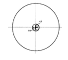
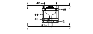
図3A~図3Cには、キャップ40の詳細構造を示す。図3Aはキャップ40の平面図、図3Bはキャップ40の断面図、図3Cはキャップ40に設けられた凹部の断面拡大図をそれぞれ示す。
図3Bまたは図3Cに示すように、キャップ40の中央部には凹部が設けられている。この凹部は、試料19の設置部であると同時に容器30から上昇してくるガスを試料に対して供給するガス供給機能を備えている。
この凹部の底面には、容器30から上がってくるガスを通過させる貫通孔41が形成され、貫通孔41の上部に、試料台45が設置される。試料台45の外周部には、試料19を囲むように貫通孔41と連通する穴47が4箇所開いており、貫通孔41を通って上昇してくるガスが穴47を通過する。
試料台45と貫通孔41の間には、貫通孔41から供給されるガスの流量を制限するための環状の絞り部材42が設置されている。絞り部材42には穴が空けてあり、穴の径は数μm~数mmの範囲が実用的である。絞り部材42の上部には、絞り部材42を固定する絞り押さえ43が設けられる。絞り押さえ43の中央部にも、絞り部材42を通ったガスが通過できるように穴46が空けられている。
ガス流量が多くてもよい場合には、絞り部材42を使用せずに貫通孔41の径を変えることで対応してもよい。ただし、貫通孔41の直径は一度キャップを製造してしまうと決まってしまうので、ガス流量を調整する場合には、穴径の異なる貫通孔を有するキャップ40を複数用意する必要がある。従って、原理的には絞り部材42は無くても良いが、ガス流量を簡便にコントロールできる点であった方がよい。この際、図4に示すように穴径の異なる絞り部材を複数準備しておき、観察したい真空度に応じて絞り部材42を交換することで、簡便にガス流量を調整することができる。
被観察試料である試料19を交換する場合、あるいは絞り部材42を交換する場合には、凹部から試料台45あるいは絞り部材42を取り出す必要がある。このため、試料台45および絞り押さえ43の昇降機構として、凹部の内壁面にネジ溝44(めねじ)を形成し、同時に試料台45と絞り押さえ43の側面にもネジ溝(おねじ)を形成しておく。試料台45における昇降機構は、試料19の高さ合わせ機能も兼ねることで、高さの異なる試料に入れ替えた場合でも常に試料19の最上部はキャップ40の上面と同じ高さになるように設定できる。また、絞り押さえ43の外周部に、穴46とは別の穴(または窪み)を複数形成しておき、この穴にピンセットなどの適当な冶具をはめてネジ溝に沿って回すことにより、絞り押さえ43を取り外せるように構成する。試料台45には、A図に示すように、もともと複数の穴47が開いているため、凹部から試料台45を取り外す際にはこの穴47が利用できる。
ネジ溝以外の昇降機構を利用できることは言うまでもないが、試料台45と絞り押さえ43の昇降機構としては、上述のようにネジ溝を利用する方式が最も簡便である。なお、絞り部材42の直径を凹部に嵌合するよう構成し、絞り部材42の側面にねじ山を切れば、絞り押さえ43は不要となる。
総合的には、図3Bおよび図3Cに示すガス経路48のような流路が形成され、試料近傍にガスが流れ込むようになる。このようにして、外部からガスを供給することなく、最小量のガスで効率的に試料近傍を低真空にすることができる。
(実施例2)
本実施例では、より効果的に試料19近傍を低真空にするための構成を示す。図4に示すように、図3A、図3Bおよび図3Cで示したキャップ40の上部に上蓋50(第2の蓋部材)を、ねじ等を利用して取り付ける。上蓋50には、凹部ないし試料台45よりも径の小さい中心穴51が空いており、試料19の下部から上がってきたガスが試料19上部で絞られる構造になっている。このためガス経路52に示すように流路の中に試料19が設置されるので、実施例1と同じガス流量で比較すると試料近傍の真空度がより低真空となる。
本実施例では、より効果的に試料19近傍を低真空にするための構成を示す。図4に示すように、図3A、図3Bおよび図3Cで示したキャップ40の上部に上蓋50(第2の蓋部材)を、ねじ等を利用して取り付ける。上蓋50には、凹部ないし試料台45よりも径の小さい中心穴51が空いており、試料19の下部から上がってきたガスが試料19上部で絞られる構造になっている。このためガス経路52に示すように流路の中に試料19が設置されるので、実施例1と同じガス流量で比較すると試料近傍の真空度がより低真空となる。
さらに、上蓋50が絞りの役目も果たすので、上蓋50下部の部屋の真空度を低く保つことができると共に試料室5に流れるガスも少なくなる。試料室5の真空度の劣化は少なくすることができる。
図6には、キャップ40の変形例を示す。キャップ60では、試料19下部からガスを当てるのではなく、試料19の側面に貫通孔61を設けることでガス噴射方向に試料があり、試料台45の試料載置面上でガス通過穴の位置よりも外側に広がって載置するような大きい試料など、下部からガスが出せない場合に有効である。また、噴射ガスを直接試料に上部、すなわち観察面に当てることで、さらなる低真空化が期待できるメリットもある。なお、図5に示した上蓋50を図6のキャップ60に被せることで、上記のような大きい試料に対してより低真空度な状態で観察が可能という効果がある。
1 走査電子顕微鏡
2 電子銃室
3 集束レンズ室
4 対物レンズ室
5 試料室
6 電子源
7 集束レンズ
8 対物レンズ
9 試料微動装置
10 試料交換室
11,12 イオンポンプ
13 ターボ分子ポンプ
14 ロータリーポンプ
15,16 バルブ
17 試料ホルダー
18 ガス源
19 試料
22 試料交換棒
30 容器
31,44 ネジ溝
32 Oリング
33 アタッチメント
40,60 キャップ
41,61 貫通孔
42 絞り部材
43 絞り押さえ
45 試料台
46,47 穴
48,52 ガス経路
50,72 上蓋
51 中心穴
2 電子銃室
3 集束レンズ室
4 対物レンズ室
5 試料室
6 電子源
7 集束レンズ
8 対物レンズ
9 試料微動装置
10 試料交換室
11,12 イオンポンプ
13 ターボ分子ポンプ
14 ロータリーポンプ
15,16 バルブ
17 試料ホルダー
18 ガス源
19 試料
22 試料交換棒
30 容器
31,44 ネジ溝
32 Oリング
33 アタッチメント
40,60 キャップ
41,61 貫通孔
42 絞り部材
43 絞り押さえ
45 試料台
46,47 穴
48,52 ガス経路
50,72 上蓋
51 中心穴
Claims (11)
- 真空試料室に格納される試料に対し電子線を照射して、前記試料の画像を取得する電子顕微鏡で使用される電子顕微鏡用試料ホルダーであって、
ガス源となる物質を格納する容器と、
当該容器が、
前記試料を載置する試料台と、
前記容器内の物質に起因して発生するガスを前記試料台上の試料に対して供給する機構を備えることを特徴とする電子顕微鏡用試料ホルダー。 - 請求項1に記載の電子顕微鏡用試料ホルダーにおいて、
前記蓋部材の上面側に設けられた凹部と、
当該凹部の奥に形成された、前記凹部の内径よりも直径の小さな貫通孔と、をさらに備え、 前記試料台が前記凹部の内部に配置されることを特徴とする電子顕微鏡用試料ホルダー。 - 請求項2に記載の電子顕微鏡用試料ホルダーにおいて、
前記凹部の内部であって前記試料台の下部に配置される絞り部材と、
当該絞り部材を前記凹部内の所定位置に固定する絞り押さえと、をさらに備え、
前記絞り部材は前記ガスを透過させる貫通孔を備えたことを特徴とする電子顕微鏡用試料ホ
ルダー。 - 請求項3に記載の電子顕微鏡用試料ホルダーにおいて、
前記絞り部材は前記貫通孔を備える環状板部材であることを特徴とする電子顕微鏡用試料ホルダー。 - 請求項4に記載の電子顕微鏡用試料ホルダーにおいて、
穴径の異なる前記貫通孔を備える複数の前記絞り部材を交換することにより、前記試料に対して供給するガスの流量を調整できることを特徴とする電子顕微鏡用試料ホルダー。 - 請求項2に記載の電子顕微鏡用試料ホルダーにおいて、
前記試料台または前記絞り押さえを前記凹部内で上下動させる昇降機構をさらに備えたことを特徴とする電子顕微鏡用試料ホルダー。 - 請求項6記載の電子顕微鏡用試料ホルダーにおいて、
前記昇降機構は、前記試料台または前記絞り押さえの外周部および前記凹部の内壁面に形成されたネジ溝であることを特徴とする電子顕微鏡用試料ホルダー。 - 請求項2に記載の電子顕微鏡用試料ホルダーにおいて、
前記蓋部材の上部に、前記試料台の直径よりも小さな直径貫通孔を有する第2の蓋部材を取り付け可能なことを特徴とする電子顕微鏡用試料ホルダー。 - 請求項1から8のいずれか1項に記載の電子顕微鏡用試料ホルダーにおいて、
前記電子顕微鏡の試料微動装置に直接取り付け可能なアタッチメントをさらに備えることを特徴とする電子顕微鏡用試料ホルダー。 - 試料を格納する真空試料室と、
前記試料に対して電子線を照射する機能を有する電子光学鏡筒と、
前記電子線の照射により得られる二次電子ないし反射電子を検出する検出器と、
前記真空試料室内に格納されて使用される試料ホルダーと、を備える電子顕微鏡において、
前記試料ホルダーは、
ガス源となる物質を格納する容器と、
当該容器に対して真空シールされて嵌合される蓋部材と、を備え、
当該蓋部材が、
前記試料を載置する試料台と、
前記容器内の物質に起因して発生するガスを前記試料台上の試料に対して供給する機構と、を備えることを特徴とする電子顕微鏡用試料ホルダー。 - 真空試料室内に置かれた試料に対し電子線を照射し、得られる二次電子ないし反射電子を検出して画像化することにより前記試料を観察する観察方法において、
ガス源となる物質を格納する容器と該当容器に試料ホルダーと前記試料を載置し、
前記真空試料室内の圧力によって前記容器内の物質を揮発させることにより、前記試料の載置位置に局所的な低真空状態を形成し、
当該試料に対して前記電子線を照射して前記試料の画像を取得することを特徴とする観
察方法。
Priority Applications (2)
| Application Number | Priority Date | Filing Date | Title |
|---|---|---|---|
| DE112011105007.0T DE112011105007B4 (de) | 2011-03-04 | 2011-11-02 | Probenhalter für ein Elektronenmikroskop und Probenuntersuchungsverfahren |
| CN201180067087.9A CN103348439B (zh) | 2011-03-04 | 2011-11-02 | 电子显微镜用试样支架及试样观察方法 |
Applications Claiming Priority (2)
| Application Number | Priority Date | Filing Date | Title |
|---|---|---|---|
| JP2011047069 | 2011-03-04 | ||
| JP2011-047069 | 2011-03-04 |
Publications (1)
| Publication Number | Publication Date |
|---|---|
| WO2012120728A1 true WO2012120728A1 (ja) | 2012-09-13 |
Family
ID=46797710
Family Applications (2)
| Application Number | Title | Priority Date | Filing Date |
|---|---|---|---|
| PCT/JP2011/075001 Ceased WO2012120726A1 (ja) | 2011-03-04 | 2011-10-28 | 電子顕微鏡用試料ホルダーおよび試料観察方法 |
| PCT/JP2011/075334 Ceased WO2012120728A1 (ja) | 2011-03-04 | 2011-11-02 | 電子顕微鏡用試料ホルダーおよび試料観察方法 |
Family Applications Before (1)
| Application Number | Title | Priority Date | Filing Date |
|---|---|---|---|
| PCT/JP2011/075001 Ceased WO2012120726A1 (ja) | 2011-03-04 | 2011-10-28 | 電子顕微鏡用試料ホルダーおよび試料観察方法 |
Country Status (6)
| Country | Link |
|---|---|
| US (1) | US9159530B2 (ja) |
| JP (1) | JP5584819B2 (ja) |
| KR (1) | KR20130126684A (ja) |
| CN (1) | CN103348439B (ja) |
| DE (1) | DE112011105007B4 (ja) |
| WO (2) | WO2012120726A1 (ja) |
Families Citing this family (15)
| Publication number | Priority date | Publication date | Assignee | Title |
|---|---|---|---|---|
| EP2626885A1 (en) * | 2012-02-13 | 2013-08-14 | FEI Company | Forming a vitrified sample for an electron microscopy |
| JP6364167B2 (ja) * | 2013-09-30 | 2018-07-25 | 株式会社日立ハイテクノロジーズ | 環境制御型荷電粒子観察システム |
| USD794816S1 (en) * | 2013-10-24 | 2017-08-15 | Hitachi High-Technologies Corporation | Sample holder for an electron microscope |
| US9449785B2 (en) | 2013-11-11 | 2016-09-20 | Howard Hughes Medical Institute | Workpiece transport and positioning apparatus |
| KR200472397Y1 (ko) * | 2014-01-13 | 2014-04-23 | 박명원 | 콜드 마운팅용 지그 |
| CN104142302B (zh) | 2014-07-28 | 2017-02-15 | 中国科学院生物物理研究所 | 一种光镜电镜关联成像用光学真空冷台 |
| TWI546841B (zh) | 2014-12-10 | 2016-08-21 | 財團法人工業技術研究院 | 具有載台的電子顯微鏡 |
| CN107389455B (zh) * | 2017-09-05 | 2023-06-06 | 中国工程物理研究院流体物理研究所 | 用于磁驱动斜波压缩中样品初始温度的降温装置及方法 |
| DE202018103852U1 (de) | 2018-07-05 | 2018-08-17 | Leibniz-Institut Für Polymerforschung Dresden E.V. | Probenhalter für Rasterelektronenmikroskope |
| DE102018132770B3 (de) * | 2018-12-19 | 2020-04-02 | Fraunhofer-Gesellschaft zur Förderung der angewandten Forschung e.V. | Vorrichtung zur Probenuntersuchung für ein atmosphärisches oder druckvariables Rasterelektronenmikroskop, Mikroskopiesystem sowie Mikroskopieverfahren |
| US10777379B1 (en) * | 2019-03-19 | 2020-09-15 | Hitachi High-Tech Corporation | Holder and charged particle beam apparatus |
| KR102267695B1 (ko) | 2019-12-12 | 2021-06-22 | 권영진 | 냉, 난방용 배관파이프 테이프 권취기 |
| DE102020111151B4 (de) | 2020-04-23 | 2023-10-05 | Carl Zeiss Microscopy Gmbh | Verfahren zum Belüften und Abpumpen einer Vakuumkammer eines Teilchenstrahlgeräts, Computerprogrammprodukt und Teilchenstrahlgerät zur Durchführung des Verfahrens |
| CN115702341A (zh) * | 2020-06-09 | 2023-02-14 | 国立研究开发法人物质·材料研究机构 | 观测对象气体的观测装置和观测对象离子的观测方法以及试样支架 |
| KR102356197B1 (ko) | 2020-06-15 | 2022-01-27 | 권영진 | 배관파이프 테이프권취기 |
Citations (2)
| Publication number | Priority date | Publication date | Assignee | Title |
|---|---|---|---|---|
| JP2004037112A (ja) * | 2002-06-28 | 2004-02-05 | Canon Inc | 核酸チップ基板、及び核酸チップの検査方法、並びに製造方法 |
| JP2009245944A (ja) * | 2008-03-28 | 2009-10-22 | Fei Co | 粒子光学装置用環境セル |
Family Cites Families (10)
| Publication number | Priority date | Publication date | Assignee | Title |
|---|---|---|---|---|
| GB1477458A (en) * | 1974-10-28 | 1977-06-22 | Shah J | Specimen stages for electron beam instruments |
| US4705949A (en) * | 1985-11-25 | 1987-11-10 | The United States Of America As Represented By The Secretary Of Commerce | Method and apparatus relating to specimen cells for scanning electron microscopes |
| JP2766667B2 (ja) * | 1989-05-25 | 1998-06-18 | 日本電子株式会社 | 凍結試料移送装置 |
| JP2794471B2 (ja) | 1989-11-24 | 1998-09-03 | 日本電子テクニクス株式会社 | 電子顕微鏡 |
| JPH08250057A (ja) * | 1995-03-08 | 1996-09-27 | Jeol Ltd | 走査電子顕微鏡の試料ホルダー |
| JP2002134057A (ja) * | 2000-10-24 | 2002-05-10 | Hitachi Ltd | 走査電子顕微鏡 |
| CN2459650Y (zh) * | 2000-11-13 | 2001-11-14 | 中国科学院化工冶金研究所 | 一种在环境扫描电镜中直接观察含水生物样品的装置 |
| JP3926103B2 (ja) * | 2001-01-15 | 2007-06-06 | 日本電子株式会社 | 冷却ホルダ並びに走査電子顕微鏡 |
| US6979822B1 (en) | 2002-09-18 | 2005-12-27 | Fei Company | Charged particle beam system |
| CN101067992A (zh) * | 2006-04-26 | 2007-11-07 | 李炳寰 | 在真空或低压环境中操作气体且可供观测的装置 |
-
2011
- 2011-10-28 WO PCT/JP2011/075001 patent/WO2012120726A1/ja not_active Ceased
- 2011-10-28 JP JP2013503331A patent/JP5584819B2/ja active Active
- 2011-10-28 US US14/002,056 patent/US9159530B2/en active Active
- 2011-10-28 KR KR1020137020983A patent/KR20130126684A/ko not_active Ceased
- 2011-11-02 CN CN201180067087.9A patent/CN103348439B/zh not_active Expired - Fee Related
- 2011-11-02 WO PCT/JP2011/075334 patent/WO2012120728A1/ja not_active Ceased
- 2011-11-02 DE DE112011105007.0T patent/DE112011105007B4/de not_active Expired - Fee Related
Patent Citations (2)
| Publication number | Priority date | Publication date | Assignee | Title |
|---|---|---|---|---|
| JP2004037112A (ja) * | 2002-06-28 | 2004-02-05 | Canon Inc | 核酸チップ基板、及び核酸チップの検査方法、並びに製造方法 |
| JP2009245944A (ja) * | 2008-03-28 | 2009-10-22 | Fei Co | 粒子光学装置用環境セル |
Also Published As
| Publication number | Publication date |
|---|---|
| CN103348439B (zh) | 2016-09-28 |
| US9159530B2 (en) | 2015-10-13 |
| JP5584819B2 (ja) | 2014-09-03 |
| US20140014835A1 (en) | 2014-01-16 |
| WO2012120726A1 (ja) | 2012-09-13 |
| DE112011105007B4 (de) | 2021-01-21 |
| DE112011105007T5 (de) | 2013-12-12 |
| CN103348439A (zh) | 2013-10-09 |
| KR20130126684A (ko) | 2013-11-20 |
| JPWO2012120726A1 (ja) | 2014-07-07 |
Similar Documents
| Publication | Publication Date | Title |
|---|---|---|
| JP5584819B2 (ja) | 電子顕微鏡用ホルダー、電子顕微鏡及び試料観察方法 | |
| US20140123898A1 (en) | Charged particle beam device | |
| US20200035448A1 (en) | Vacuum condition controlling apparatus, system and method for specimen observation | |
| WO2002037527A1 (fr) | Appareil a faisceau electronique et procede de production de dispositif utilisant cet appareil | |
| WO2013129143A1 (ja) | 荷電粒子線装置 | |
| KR20180109687A (ko) | 하전 입자 빔 장치 | |
| US10269533B2 (en) | Anti-contamination trap, and vacuum application device | |
| US10340117B2 (en) | Ion beam device and sample observation method | |
| US9916963B2 (en) | Specimen loading method, specimen stage, and charged particle beam device | |
| US20250239433A1 (en) | Focused Ion Beam System | |
| WO2015045477A1 (ja) | 試料ホールダ及び荷電粒子装置 | |
| US10651005B2 (en) | Innovative source assembly for ion beam production | |
| US10741357B2 (en) | Method of observing liquid specimen, method of analyzing liquid specimen and electron microscope | |
| KR102552225B1 (ko) | 주사 전자 현미경 | |
| WO2014069325A1 (ja) | 電子ビーム顕微装置 | |
| US10651007B2 (en) | Cryogenic cell for mounting a specimen in a charged particle microscope | |
| JP7117107B2 (ja) | 衝突イオン化源 | |
| KR101798473B1 (ko) | 고분해능 주사전자현미경 | |
| JPH04286843A (ja) | 走査形電子顕微鏡及びその類似装置の可動絞り装置 | |
| JP3944384B2 (ja) | 集束イオンビーム加工装置 | |
| JPWO2002001597A1 (ja) | 荷電粒子線による検査装置及びその検査装置を用いたデバイス製造方法 | |
| JP2009032603A (ja) | マーキング装置 | |
| JP2018101557A (ja) | イオン顕微鏡 |
Legal Events
| Date | Code | Title | Description |
|---|---|---|---|
| 121 | Ep: the epo has been informed by wipo that ep was designated in this application |
Ref document number: 11860413 Country of ref document: EP Kind code of ref document: A1 |
|
| WWE | Wipo information: entry into national phase |
Ref document number: 112011105007 Country of ref document: DE Ref document number: 1120111050070 Country of ref document: DE |
|
| 122 | Ep: pct application non-entry in european phase |
Ref document number: 11860413 Country of ref document: EP Kind code of ref document: A1 |