WO2012120609A1 - 保磁力特定装置 - Google Patents
保磁力特定装置 Download PDFInfo
- Publication number
- WO2012120609A1 WO2012120609A1 PCT/JP2011/055199 JP2011055199W WO2012120609A1 WO 2012120609 A1 WO2012120609 A1 WO 2012120609A1 JP 2011055199 W JP2011055199 W JP 2011055199W WO 2012120609 A1 WO2012120609 A1 WO 2012120609A1
- Authority
- WO
- WIPO (PCT)
- Prior art keywords
- coercive force
- magnet
- distribution magnet
- force distribution
- coercivity
- Prior art date
- Legal status (The legal status is an assumption and is not a legal conclusion. Google has not performed a legal analysis and makes no representation as to the accuracy of the status listed.)
- Ceased
Links
Images



Classifications
-
- G—PHYSICS
- G01—MEASURING; TESTING
- G01R—MEASURING ELECTRIC VARIABLES; MEASURING MAGNETIC VARIABLES
- G01R33/00—Arrangements or instruments for measuring magnetic variables
- G01R33/12—Measuring magnetic properties of articles or specimens of solids or fluids
- G01R33/1215—Measuring magnetisation; Particular magnetometers therefor
-
- G—PHYSICS
- G01—MEASURING; TESTING
- G01R—MEASURING ELECTRIC VARIABLES; MEASURING MAGNETIC VARIABLES
- G01R33/00—Arrangements or instruments for measuring magnetic variables
- G01R33/12—Measuring magnetic properties of articles or specimens of solids or fluids
- G01R33/16—Measuring susceptibility
-
- G—PHYSICS
- G01—MEASURING; TESTING
- G01R—MEASURING ELECTRIC VARIABLES; MEASURING MAGNETIC VARIABLES
- G01R33/00—Arrangements or instruments for measuring magnetic variables
- G01R33/12—Measuring magnetic properties of articles or specimens of solids or fluids
- G01R33/123—Measuring loss due to hysteresis
Definitions
- the present invention creates a demagnetization curve for each divided region of a coercive force distribution magnet used for a motor and the like, specifies an average coercive force of each divided region, and implements this in all the divided regions, thereby coercive force.
- the present invention relates to a coercive force specifying device for specifying the coercive force of a distributed magnet.
- a permanent magnet embedded in a rotor such as an IPM motor is required to have a coercive force that can resist demagnetization due to an external magnetic field incident from the stator core side.
- the external magnetic field acting on the permanent magnet is generally such that when the rotor in which the permanent magnet is embedded is viewed in plan, the corner portion on the stator core side of the permanent magnet is the largest and the center side of the rotor core is small. .
- metal particles for enhancing the coercive force performance of the permanent magnets are diffused from the surface of the sintered permanent magnets.
- the metal particles are made of rare earth such as dysprosium and terbium. Therefore, how to reduce the use amount while ensuring the coercive force performance desired from the viewpoint of reducing the manufacturing cost of the permanent magnet is one of the important solutions in the technical field.
- the coercive force performance is different for each part of the permanent magnet because the magnitude of the external magnetic field acting on each part of the permanent magnet is different.
- the amount of rare earth used can be reduced as much as possible, and the production of a permanent magnet that can reduce the production cost can be realized.
- the optimum design is to make the magnetic characteristics of the side surface portion of the stator relatively good due to the flow of magnetic flux from the stator side. May be made.
- the coercive force of each internal portion is accurately identified, and the quality of the coercive force distribution magnet that is the target of identification is further determined for each desired portion. Guaranteeing with high accuracy is extremely important for the future development of products (for example, magnets) and for the trust of magnet manufacturers and manufacturers using magnets.
- JP 2001-141701 A Japanese Patent Laid-Open No. 5-264704
- the present invention has been made in view of the above-described problems, and creates a demagnetization curve for each divided region in which the coercive force distribution magnet can be arbitrarily divided into areas without destroying the coercive force distribution magnet.
- the coercive force can be specified for each divided region with high accuracy, and the coercive force of the coercive force distribution magnet can be accurately specified for each divided region.
- An object is to provide a specific device.
- a coercive force identification device includes a yoke having an insertion space into which a coercive force distribution magnet having a different coercive force is inserted for each part, an excitation coil for generating a magnetic field in the yoke, A search coil that detects a change in magnetization when the magnetic field is applied to the coercive force distribution magnet, and a tracer that creates a demagnetization curve based on a voltage value generated by the change in magnetization.
- Two or more loop-shaped grooves are opened on the end face facing the insertion space, and the search coil made of the conductive wire and the surrounding insulating film is disposed in each groove, and two or more loops are provided in the coercive force distribution magnet.
- Each of the search coils has a corresponding divided region, and a voltage value due to a magnetization change detected by each search coil is transmitted to the tracer, so that the demagnetization curve of the corresponding divided region is transmitted.
- the coercive force distribution magnet to be specified by the coercive force specifying device of the present invention is used at the time of manufacturing a magnet, when manufacturing an IPM motor including the magnet, and when manufacturing a vehicle including the IPM motor, in order to confirm performance after manufacturing.
- the coercive force distribution magnet at any of the above timings, or the coercive force distribution magnet taken out from the rotor after being placed in an arbitrary environment such as after the vehicle travels on the market.
- examples of the coercive force distribution magnet include a permanent magnet having a coercive force distribution for a motor.
- a ternary neodymium magnet in which iron and boron are added to neodymium, and a binary alloy of samarium and cobalt is added to neodymium, and a binary alloy of samarium and cobalt.
- the loop-shaped groove provided on the end surface facing the insertion space of the yoke, which is a magnetic body, the number of search coils arranged in the groove, and the area included in each search coil are the area of the coercive force distribution magnet.
- the area of the divided region for which the average coercive force is to be specified (the divided region is a region surrounded by the search coil, and the average coercive force of each region can be obtained by the coercive force specifying device of the present invention).
- the coercive force distribution magnet is divided into two divided regions, and a demagnetization curve of each divided region is created and each divided region When the three loop search coils are applied, demagnetization curves of three divided regions are created and their average coercivity is specified.
- a BH curve tracer can be applied, which is based on the magnetization change of the coercive force distribution magnet when the magnetic field generated by the exciting coil is applied to the coercive force distribution magnet.
- the voltage value is detected by the search coil, this voltage value is transmitted from the search coil to the integrator built in the BH curve tracer, and the voltage value generated by the magnetization change is time-integrated by the integrator to obtain the magnetic flux density.
- the demagnetization curve (BH curve or 4 ⁇ IH curve) is created based on the calculated value.
- the coercive force (Hcj) specified from the demagnetization curve is an average coercive force of the divided region of the coercive force distribution magnet corresponding to each search coil.
- the demagnetization curve is created for each desired divided region by arbitrarily adjusting the radix of the search coil and its shared area, and the average coercive force is identified. Therefore, it is possible to specify the average coercivity for each part of the coercive force distribution magnet with high accuracy.
- the depth of the groove is 1 mm or less.
- the material characteristic value of the coercive force distribution magnet (by arranging the search coil made of the conductive wire and the surrounding insulating coating inside the groove with a depth of 1 mm or less is provided. It has been demonstrated that the coercivity of the target area can be specified with an error accuracy within 0.1% of Hcj).
- the width of the groove is preferably 0.3 mm or less.
- the target area is within 0.1% error accuracy with respect to the material characteristic value (Hcj) of the coercive force distribution magnet. It has been demonstrated that the coercivity of can be specified.
- the groove has a depth of 1 mm or less and a width of 0.3 mm or less. Further, the dimensions that can be manufactured for the search coil disposed in the groove (an enameled wire or a copper-made conductive wire as an insulating coating) For example, a groove with a depth of 1 mm and a width of 0.3 mm is preferable.
- a preferred embodiment of the coercive force identification device includes a yoke having an insertion space into which a coercive force distribution magnet having a different coercive force for each part is inserted, an excitation coil for generating a magnetic field in the yoke, and a coercive force.
- a search coil that detects a change in magnetization when the magnetic field is applied to the distributed magnet; and a tracer that creates a demagnetization curve based on a voltage value generated by the change in magnetization.
- Two or more search coils formed by patterning a conductive film on the surface of the resin film and the surface of the resin film are arranged on the end surface facing the surface, and each of the two or more search coils in the coercive force distribution magnet corresponds to a divided region.
- the voltage value due to the magnetization change detected by each search coil is transmitted to the tracer, and the corresponding demagnetization curve is created. Rutotomoni average coercive force is identified, this is what the coercive force of all be carried out in divided areas coercivity distribution magnet is identified.
- the coercive force distribution magnet when the coercive force distribution magnet is inserted into the insertion space and this surface comes into close contact with the end face of the yoke, the coercive force distribution magnet is magnetic. (Yoke) and air gaps (grooves) will come into contact with the close contact surface, and the permeance (the operating point on the demagnetization curve of the magnet. The magnetic field passing in the direction opposite to the magnetization direction of the magnet becomes larger).
- a resin film and a surface on which two or more search coils formed by patterning a conductive material in a loop shape are provided.
- the form of patterning of the conductive material (metal such as copper) described above is arbitrary, and examples include forms by printing and forms by etching.
- coercive force identification device of the present invention can be applied to, for example, the following coercive force identification method of a coercive force distribution magnet.
- the coercive force identification method of this coercive force distribution magnet is such that the coercive force is different in a plane formed by cutting in the direction along the easy magnetization direction among the coercive force distribution magnets, and from the center to the outer peripheral side in the plane.
- a coercive force distribution magnet specifying method for specifying a coercive force at an arbitrary position on the plane the coercive force distribution magnet is provided on the plane of the coercive force distribution magnet.
- the coercive force distribution graph is used to specify a coercive force at an arbitrary position in the plane in the coercive force distribution magnet.
- This coercive force identification method cuts the magnet in a plane when the coercive force distribution magnet is cut in the easy magnetization direction, that is, in a direction perpendicular to the slot axis when the magnet is disposed in the rotor slot.
- the coercive force at an arbitrary position in the plane of the coercive force distribution magnet exhibiting a coercive force distribution in which the coercive force increases from the center toward the outer peripheral side can be precisely specified. It is a coercive force identification method.
- one side thereof is a side surface on the stator side, and the other side facing this is a side surface on the rotor central side.
- the coercive force decreases from the outer periphery to the center of the magnet. It becomes a coercive force distribution magnet.
- the coercive force distribution state in a plane that can be cut at an arbitrary level in the height direction has almost the same tendency regardless of the level at which it is cut, that is, in the plane. It can be said that the coercive force tends to increase concentrically from the center toward the outer peripheral side.
- the coercive force distribution in this plane is specified, and this is expanded in the height direction of the magnet.
- a plurality of divided regions extending in the easy magnetization direction with respect to the plane of the coercive force distribution magnet are virtually set, and the coercive force distribution magnet is arranged in the coercive force specifying device of the present invention.
- a search coil is arranged at a position corresponding to each of the divided regions, and a demagnetization curve unique to each divided region is created from the measurement result of each search coil.
- the magnet plane is temporarily divided into a plurality of band-like areas by virtually setting a band-like divided area along the easy magnetization direction with respect to the magnet plane having a rectangular shape in plan view.
- This easy magnetization direction is, for example, a direction from the rotor center side toward the stator side when the coercive force distribution magnet is disposed in the rotor slot as described above.
- Coordinate system consisting of coercive force coordinates and residual magnetic flux density (magnetization) coordinates by applying an external reverse magnetic field to the coercive force distribution magnet to be identified using the coercive force identification device of the present invention.
- a demagnetization curve can be created in (second quadrant).
- a search coil is provided for each of the above virtually divided divided areas, and a demagnetization curve of the divided areas corresponding to each search coil is created.
- the coercive force of the central divided region is low, and the upper and lower divided regions adjacent thereto have the same high coercive force.
- the upper and lower divided areas adjacent to each other tend to have a higher coercive force to the same extent. That is, when the central divided region is BA1, the upper and lower divided regions perpendicular to the easy magnetization direction are BA2 and 3, and the upper and lower divided regions adjacent to these are BA4 and 5, respectively.
- the position (BA1) corresponding to the central divided area for example, the upper divided area (BA2) adjacent to this, and the upper divided area (BA4) adjacent to this, in total 3 places It is sufficient to provide a search coil in (a demagnetization curve of BA3 and BA5 can use that of BA2 and BA4, respectively).
- the minimum coercive force: H min and the average coercive force: Hcj are specified from each of the created demagnetization curves, and the center position of the divided region is set to x1, and the left and right outer peripheries thereof.
- the coercive force at the inflection point where the residual magnetic flux density decreases can be made the minimum coercive force, and further the demagnetization can be achieved.
- the average coercive force can be determined by the point where the demagnetization curve intersects the coercive force coordinates.
- the minimum coercivity and the average coercivity are set for each demagnetization curve.
- the distance from the center of the divided area to the outer circumference is taken as the X axis, and the coercive force at each distance is taken as the Y axis.
- the three assumptions are as follows: (1) In the coercive force distribution graph, the coercive force at the center position: x1 is H x1 and the minimum coercive force is H min, and (2) the positions are ⁇ x2 and ⁇ x3, respectively.
- H ⁇ x3 and H + x3 , and H ⁇ x2 and H + x2 are equal in coercive force at the same distance from the center position.
- H + x2 and H + x3 are specified from the above equations (2) and (3).
- H x1 H min
- the distance from the center of the divided region to the outer peripheral side is taken as the X axis
- the coercive force identification device of the present invention it is possible to create a demagnetization curve for each divided region arbitrarily divided without destroying the coercive force distribution magnet, And each average coercive force can be specified with high precision, and the coercive force distributed by the coercive force distribution magnet can be specified with high accuracy.
- FIG. 2 is an II-II arrow view of FIG. 1.
- A) is the enlarged view of the III part of FIG. 1
- (b) is a figure corresponding to (a), and is the figure which showed other embodiment of the arrangement
- the coercive force distribution magnet is temporarily divided into three divided regions, a demagnetization curve for each divided region is created, and the average coercive force is specified.
- the number may be two, four or more.
- FIG. 1 is a schematic diagram illustrating an embodiment of the coercive force identification device according to the present invention
- FIG. 2 is a view taken along the line II-II in FIG. 1
- FIG. 3a is an enlarged view of a portion III in FIG. is there.
- the coercive force identification device 10 shown in the figure has a substantially C-shaped yoke 1 having an insertion space 1a into which coercive force distribution magnets M having different coercive forces are inserted for each part, and generates a magnetic field in the yoke 1.
- the excitation coil 2 (in the magnetic flow X direction), a power source (not shown) that supplies current to the excitation coil 2, a search coil 3 that detects a change in magnetization when a magnetic field is applied to the coercive force distribution magnet M,
- a tracer 4 (BH curve tracer) that creates a demagnetization curve based on a voltage value generated by the magnetization change is roughly constituted.
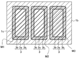
- three loop-shaped grooves 1c, 1c, and 1c are opened on the end face 1b facing the insertion space 1a of the yoke 1, and a copper wire is provided in each groove 1c.
- a search coil 3 composed of 3a and the surrounding insulating coating 3b is disposed.
- each search coil 3 has a corresponding divided region M1, M2, M3 of the coercive force distribution magnet, and the conductive wire extending from each search coil 3 is connected to an integrator 4a built in the tracer 4. ing.
- the detected voltage value is transmitted from the search coil 3 to an integrator incorporated in the search coil 3, and time integrated by the integrator 4a to calculate the magnetic flux density. Based on this, the divided regions M1, M2, M3 (in each search coil) A demagnetization curve (BH curve or 4 ⁇ IH curve) for each enclosed region is created.
- the coercive force (Hcj) specified from the demagnetization curve for each of the divided areas M1, M2, and M3 is an average coercive force in each divided area.
- the groove depth h is 1 mm or less and the groove width w from the magnetic field analysis result described later. Is preferably 0.3 mm or less, and the depth can be determined, for example, by taking into account the manufacturable dimensions of the search coil disposed therein (dimensions such as enameled wire that becomes an insulating film or copper conductive wire). Is preferably 1 mm and a groove width of 0.3 mm.
- the search coil 3 is accommodated in the groove 1c, and an air gap A is formed in the upper part (coercive force distribution magnet side).
- the arrangement form of the coils may be a form in which two coils 3 are accommodated so as to be wrapped in one groove 1c, as shown in FIG. 3b.
- the coercive force distribution magnet M to be specified is a coercive force while, for example, dysprosium or terbium is diffused from the surface of a sintered permanent magnet embedded in a rotor (not shown) constituting the IPM motor while intergranular diffusion is performed.
- Is a magnet formed in a desired distribution.
- this permanent magnet a ternary neodymium magnet in which iron and boron are added to neodymium, a samarium cobalt magnet made of a binary alloy of samarium and cobalt, a ferrite magnet mainly composed of iron oxide powder Alnico magnets made from aluminum, nickel, cobalt, etc.
- the coercive force specifying device 10 By using the coercive force specifying device 10, it is possible to create a demagnetization curve for each divided region that can be divided into arbitrary areas without destroying the coercive force distribution magnet and dividing the coercive force distribution magnet.
- the average coercive force for each region can be specified with high accuracy, and by implementing this in all the divided regions, the coercive force of the coercive force distribution magnet can be specified with high accuracy for each divided region.
- FIG. 4 is a schematic diagram illustrating another embodiment of the coercive force identification device of the present invention.
- the illustrated coercive force specifying device 10A has three search coils 3A, 3A, 3A formed by patterning a conductive material in a loop shape on the surface of the resin film 5a on the end surface 1b facing the insertion space 1a of the yoke 1.
- a separate resin film 5b for sandwiching the search coil 3A together with the resin film 5a is provided, and in the coercive force distribution magnet M, each of the three search coils 3A, 3A, 3A corresponds to a divided region.
- M1, M2, and M3 are defined, and voltage values due to magnetization changes detected by the respective search coils 3A are transmitted to the tracer.
- examples of the patterning form of the conductive material such as copper include a form by printing and a form by etching.
- the coercive force distribution magnet M when the coercive force distribution magnet M is inserted into the insertion space 1a and the surface thereof comes into close contact with the end surface 1b of the yoke 1, the coercive force distribution magnet M is a magnetic body (yoke 1). And air gaps A (grooves 1c) come into contact with the close-contact surfaces that appear alternately, and permeance is likely to be distributed.
- three search coils 3A, 3A, 3A formed by patterning a conductive material in a loop shape on the surface of the resin films 5a, 5b instead of providing grooves are provided.
- the surface of the coercive force distribution magnet M that is in close contact with the surface is brought into contact with the resin film 5b made of a uniform material. It becomes possible to apply to M. This makes it difficult to distribute permeance.
- the present inventors conducted magnetic field analysis for specifying the optimum groove depth range and groove width range of the groove in the coercive force specifying device 10 shown in FIG.
- the number of turns of the exciting coil is 140, and the applied current to the exciting coil is applied until reaching the magnetic field to be applied at 0.1 A / step (excitation magnetic field (horizontal axis) obtained by this apparatus)
- a magnetic field value equal to or greater than the coercive force (Hcj) of the magnet input in the analysis was set as the magnet applied magnetic field (see FIG. 5 representing the magnetization change (vertical axis) of the magnet obtained by the search coil) (see FIG. 5).
- the groove width is set to 0.3 mm, the groove depth is changed from 0 mm to 7 mm, and the magnetic coercive force required from the apparatus having the groove of each groove depth is obtained. 6 is obtained, and the difference between the obtained magnet coercive force and the coercive force (true value) specified from the magnet material characteristic value is obtained, and the result is shown in FIG.
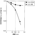
- the groove depth is set to 0.8 mm
- the groove width is changed from 0.15 mm to 0.45 mm
- the groove width of each groove width is obtained from the apparatus provided.
- the obtained magnet coercive force is obtained, and the difference between the obtained magnet coercive force and the coercive force (true value) specified from the magnet material characteristic value is obtained, and the result is shown in FIG.
- the difference from the coercive force (true value) is obtained by two search coils located at the center and end of the magnet.
- the center of the magnet is, for example, the central divided region M2 of the coercive force distribution magnet M shown in FIG. 1, and the end of the magnet is the divided region M1 or divided region M3 shown in FIG. That is.
- the groove depth of 1 mm is the inflection point. Based on this, the optimum groove depth range was defined as 1 mm or less.
Landscapes
- Physics & Mathematics (AREA)
- Condensed Matter Physics & Semiconductors (AREA)
- General Physics & Mathematics (AREA)
- Measuring Magnetic Variables (AREA)
- Hard Magnetic Materials (AREA)
- Investigating Or Analyzing Materials By The Use Of Magnetic Means (AREA)
- Soft Magnetic Materials (AREA)
Abstract
Description
本発明者等は、図1で示す保磁力特定装置10において、溝条の最適な溝深さ範囲と溝幅範囲を特定するための磁場解析をおこなった。
Claims (4)
- 保磁力が部位ごとに異なる保磁力分布磁石が挿入される挿入空間を具備するヨークと、該ヨークに磁界を発生させる励磁コイルと、保磁力分布磁石に該磁界が印加された際の磁化変化を検出するサーチコイルと、該磁化変化によって生じた電圧値に基づいて減磁曲線を作成するトレーサと、を少なくとも具備し、
ヨークの前記挿入空間に臨む端面には2以上のループ状の溝条が開設され、それぞれの溝条内に導線とその周囲の絶縁被膜からなる前記サーチコイルが配設されて、保磁力分布磁石において2以上のサーチコイルのそれぞれが対応する分割領域が規定され、
それぞれのサーチコイルにて検出された磁化変化による電圧値がトレーサに送信されて対応する分割領域の減磁曲線が作成されるとともに平均保磁力が特定され、これが全ての分割領域で実施されて保磁力分布磁石の保磁力が特定される保磁力特定装置。 - 前記溝条の深さが1mm以下である請求項1に記載の保磁力特定装置。
- 前記溝条の幅が0.3mm以下である請求項1または2に記載の保磁力特定装置。
- 保磁力が部位ごとに異なる保磁力分布磁石が挿入される挿入空間を具備するヨークと、該ヨークに磁界を発生させる励磁コイルと、保磁力分布磁石に該磁界が印加された際の磁化変化を検出するサーチコイルと、該磁化変化によって生じた電圧値に基づいて減磁曲線を作成するトレーサと、を少なくとも具備し、
ヨークの前記挿入空間に臨む端面には、樹脂フィルムとその表面に導電性素材がループ状にパターニングされてなるサーチコイルが2以上配設されて、保磁力分布磁石において2以上のサーチコイルのそれぞれが対応する分割領域が規定され、
それぞれのサーチコイルにて検出された磁化変化による電圧値がトレーサに送信されて対応する分割領域の減磁曲線が作成されるとともに平均保磁力が特定され、これが全ての分割領域で実施されて保磁力分布磁石の保磁力が特定される保磁力特定装置。
Priority Applications (5)
| Application Number | Priority Date | Filing Date | Title |
|---|---|---|---|
| US14/001,697 US8797023B2 (en) | 2011-03-07 | 2011-03-07 | Coercive force specifying apparatus |
| CN201180069072.6A CN103403566B (zh) | 2011-03-07 | 2011-03-07 | 矫顽力特定装置 |
| JP2012528964A JP5321749B2 (ja) | 2011-03-07 | 2011-03-07 | 保磁力特定装置 |
| PCT/JP2011/055199 WO2012120609A1 (ja) | 2011-03-07 | 2011-03-07 | 保磁力特定装置 |
| DE112011105011.9T DE112011105011B4 (de) | 2011-03-07 | 2011-03-07 | Vorrichtung zur Spezifizierung einer Koerzitivfeldstärke |
Applications Claiming Priority (1)
| Application Number | Priority Date | Filing Date | Title |
|---|---|---|---|
| PCT/JP2011/055199 WO2012120609A1 (ja) | 2011-03-07 | 2011-03-07 | 保磁力特定装置 |
Publications (1)
| Publication Number | Publication Date |
|---|---|
| WO2012120609A1 true WO2012120609A1 (ja) | 2012-09-13 |
Family
ID=46797617
Family Applications (1)
| Application Number | Title | Priority Date | Filing Date |
|---|---|---|---|
| PCT/JP2011/055199 Ceased WO2012120609A1 (ja) | 2011-03-07 | 2011-03-07 | 保磁力特定装置 |
Country Status (5)
| Country | Link |
|---|---|
| US (1) | US8797023B2 (ja) |
| JP (1) | JP5321749B2 (ja) |
| CN (1) | CN103403566B (ja) |
| DE (1) | DE112011105011B4 (ja) |
| WO (1) | WO2012120609A1 (ja) |
Cited By (1)
| Publication number | Priority date | Publication date | Assignee | Title |
|---|---|---|---|---|
| JP2013148508A (ja) * | 2012-01-20 | 2013-08-01 | Toyota Motor Corp | 保磁力分布磁石の保磁力特定方法 |
Families Citing this family (1)
| Publication number | Priority date | Publication date | Assignee | Title |
|---|---|---|---|---|
| US9310327B2 (en) * | 2010-02-06 | 2016-04-12 | Sgs Instruments Llc | Toroidal conductivity probe with integrated circuitry |
Citations (7)
| Publication number | Priority date | Publication date | Assignee | Title |
|---|---|---|---|---|
| JPS5068372A (ja) * | 1973-10-22 | 1975-06-07 | ||
| JPS5077067A (ja) * | 1973-06-06 | 1975-06-24 | ||
| JPS5241548A (en) * | 1975-09-25 | 1977-03-31 | Bosch Gmbh Robert | Magnet measuring device |
| JPH0464340A (ja) * | 1990-07-03 | 1992-02-28 | Toshiba Corp | Mri装置用傾斜磁場コイルの製造方法 |
| JP2006170951A (ja) * | 2004-12-20 | 2006-06-29 | Nissan Motor Co Ltd | 磁気測定装置およびその方法 |
| JP2011007512A (ja) * | 2009-06-23 | 2011-01-13 | Toyota Motor Corp | 保磁力分布磁石の保磁力特定方法 |
| JP2011022070A (ja) * | 2009-07-17 | 2011-02-03 | Fuji Electric Systems Co Ltd | 磁界センサ |
Family Cites Families (13)
| Publication number | Priority date | Publication date | Assignee | Title |
|---|---|---|---|---|
| US3614618A (en) * | 1970-05-06 | 1971-10-19 | Ncr Co | Magnetic susceptibility tester |
| EP0100009B1 (de) * | 1982-07-09 | 1985-11-13 | Fraunhofer-Gesellschaft Zur Förderung Der Angewandten Forschung E.V. | Vorrichtung zum zerstörungsfreien Messen der Einhärtetiefe von Werkstoffen |
| DE3324955C2 (de) * | 1983-07-11 | 1985-11-07 | Robert Bosch Gmbh, 7000 Stuttgart | Prüfgerät zum Prüfen von Permanentmagnetsegmenten für Elektromotoren |
| JPH05264704A (ja) * | 1992-01-28 | 1993-10-12 | Kobe Steel Ltd | 鋼板の保磁力測定方法及びその装置 |
| US5394083A (en) * | 1992-08-20 | 1995-02-28 | Iowa State University Research Foundation, Inc. | Magnetic imaging system for display of local variations of magnetic properties in magnetic material |
| CN2171874Y (zh) * | 1993-03-29 | 1994-07-13 | 东北工学院 | 永磁材料脉冲测量装置 |
| GB2324609B (en) * | 1997-04-23 | 2001-06-27 | Redcliffe Magtronics Ltd | Means for determining the characteristic of a magnetic sample |
| JPH11142492A (ja) | 1997-11-05 | 1999-05-28 | Mitsubishi Materials Corp | 磁気センサ |
| TW434411B (en) * | 1998-10-14 | 2001-05-16 | Tdk Corp | Magnetic sensor apparatus, current sensor apparatus and magnetic sensing element |
| JP2001141701A (ja) * | 1999-11-11 | 2001-05-25 | Nkk Corp | 保磁力の測定方法 |
| JP3513601B2 (ja) * | 2001-06-15 | 2004-03-31 | 岩手大学長 | 強磁性構造材の脆性の変化に伴う経年劣化の非破壊測定方法 |
| US8493062B2 (en) | 2010-03-15 | 2013-07-23 | Toyota Jidosha Kabushiki Kaisha | Method for determining coercivity of coercivity distribution magnet |
| WO2012020479A1 (ja) * | 2010-08-11 | 2012-02-16 | トヨタ自動車株式会社 | 保磁力分布磁石の保磁力性能判定装置 |
-
2011
- 2011-03-07 DE DE112011105011.9T patent/DE112011105011B4/de not_active Expired - Fee Related
- 2011-03-07 WO PCT/JP2011/055199 patent/WO2012120609A1/ja not_active Ceased
- 2011-03-07 JP JP2012528964A patent/JP5321749B2/ja not_active Expired - Fee Related
- 2011-03-07 CN CN201180069072.6A patent/CN103403566B/zh not_active Expired - Fee Related
- 2011-03-07 US US14/001,697 patent/US8797023B2/en not_active Expired - Fee Related
Patent Citations (7)
| Publication number | Priority date | Publication date | Assignee | Title |
|---|---|---|---|---|
| JPS5077067A (ja) * | 1973-06-06 | 1975-06-24 | ||
| JPS5068372A (ja) * | 1973-10-22 | 1975-06-07 | ||
| JPS5241548A (en) * | 1975-09-25 | 1977-03-31 | Bosch Gmbh Robert | Magnet measuring device |
| JPH0464340A (ja) * | 1990-07-03 | 1992-02-28 | Toshiba Corp | Mri装置用傾斜磁場コイルの製造方法 |
| JP2006170951A (ja) * | 2004-12-20 | 2006-06-29 | Nissan Motor Co Ltd | 磁気測定装置およびその方法 |
| JP2011007512A (ja) * | 2009-06-23 | 2011-01-13 | Toyota Motor Corp | 保磁力分布磁石の保磁力特定方法 |
| JP2011022070A (ja) * | 2009-07-17 | 2011-02-03 | Fuji Electric Systems Co Ltd | 磁界センサ |
Cited By (1)
| Publication number | Priority date | Publication date | Assignee | Title |
|---|---|---|---|---|
| JP2013148508A (ja) * | 2012-01-20 | 2013-08-01 | Toyota Motor Corp | 保磁力分布磁石の保磁力特定方法 |
Also Published As
| Publication number | Publication date |
|---|---|
| JPWO2012120609A1 (ja) | 2014-07-07 |
| CN103403566A (zh) | 2013-11-20 |
| US20130335064A1 (en) | 2013-12-19 |
| JP5321749B2 (ja) | 2013-10-23 |
| US8797023B2 (en) | 2014-08-05 |
| CN103403566B (zh) | 2014-07-09 |
| DE112011105011T5 (de) | 2013-11-28 |
| DE112011105011B4 (de) | 2014-08-28 |
Similar Documents
| Publication | Publication Date | Title |
|---|---|---|
| US9608485B2 (en) | Rotor for rotating electrical machine, rotating electric machine, and method for producing rotor for rotating electrical machine with magnet having surfaces tilted with respect to magnet insertion hole | |
| KR101984411B1 (ko) | 회전 전기 기기 로터 | |
| CN103326486A (zh) | 转子以及旋转电机 | |
| JP5168363B2 (ja) | 保磁力分布磁石の保磁力特定方法 | |
| JP5699948B2 (ja) | 保磁力分布磁石の保磁力特定方法 | |
| JP2010193587A (ja) | ロータ用磁石着磁装置およびモータ | |
| US9558879B2 (en) | Teardrop-shaped magnetic core and coil device using same | |
| JP5321749B2 (ja) | 保磁力特定装置 | |
| US20120313476A1 (en) | Rotor of rotating electrical machine | |
| WO2011070410A1 (en) | Motor including cleft magnet and method of manufacturing the motor | |
| US11682936B2 (en) | Motor | |
| JP5678831B2 (ja) | 保磁力分布磁石の保磁力特定方法 | |
| JP2011007512A (ja) | 保磁力分布磁石の保磁力特定方法 | |
| JP7811278B2 (ja) | 複数の磁石型を備える磁気回路 | |
| JP7271402B2 (ja) | 永久磁石回転子の製造方法 | |
| JP2026071266A (ja) | 複数の磁石型を備える磁気回路 | |
| JP2013118772A (ja) | 永久磁石埋込型モータ |
Legal Events
| Date | Code | Title | Description |
|---|---|---|---|
| ENP | Entry into the national phase |
Ref document number: 2012528964 Country of ref document: JP Kind code of ref document: A |
|
| 121 | Ep: the epo has been informed by wipo that ep was designated in this application |
Ref document number: 11860304 Country of ref document: EP Kind code of ref document: A1 |
|
| WWE | Wipo information: entry into national phase |
Ref document number: 14001697 Country of ref document: US |
|
| WWE | Wipo information: entry into national phase |
Ref document number: 112011105011 Country of ref document: DE Ref document number: 1120111050119 Country of ref document: DE |
|
| 122 | Ep: pct application non-entry in european phase |
Ref document number: 11860304 Country of ref document: EP Kind code of ref document: A1 |