WO2012117777A1 - ガスシールドアーク溶接装置 - Google Patents
ガスシールドアーク溶接装置 Download PDFInfo
- Publication number
- WO2012117777A1 WO2012117777A1 PCT/JP2012/051647 JP2012051647W WO2012117777A1 WO 2012117777 A1 WO2012117777 A1 WO 2012117777A1 JP 2012051647 W JP2012051647 W JP 2012051647W WO 2012117777 A1 WO2012117777 A1 WO 2012117777A1
- Authority
- WO
- WIPO (PCT)
- Prior art keywords
- torch
- electrode
- welding
- base
- filler wire
- Prior art date
- Legal status (The legal status is an assumption and is not a legal conclusion. Google has not performed a legal analysis and makes no representation as to the accuracy of the status listed.)
- Ceased
Links
Images





Classifications
-
- B—PERFORMING OPERATIONS; TRANSPORTING
- B23—MACHINE TOOLS; METAL-WORKING NOT OTHERWISE PROVIDED FOR
- B23K—SOLDERING OR UNSOLDERING; WELDING; CLADDING OR PLATING BY SOLDERING OR WELDING; CUTTING BY APPLYING HEAT LOCALLY, e.g. FLAME CUTTING; WORKING BY LASER BEAM
- B23K9/00—Arc welding or cutting
- B23K9/24—Features related to electrodes
- B23K9/28—Supporting devices for electrodes
- B23K9/29—Supporting devices adapted for making use of shielding means
-
- B—PERFORMING OPERATIONS; TRANSPORTING
- B23—MACHINE TOOLS; METAL-WORKING NOT OTHERWISE PROVIDED FOR
- B23K—SOLDERING OR UNSOLDERING; WELDING; CLADDING OR PLATING BY SOLDERING OR WELDING; CUTTING BY APPLYING HEAT LOCALLY, e.g. FLAME CUTTING; WORKING BY LASER BEAM
- B23K9/00—Arc welding or cutting
- B23K9/12—Automatic feeding or moving of electrodes or work for spot or seam welding or cutting
- B23K9/121—Devices for the automatic supply of at least two electrodes one after the other
-
- B—PERFORMING OPERATIONS; TRANSPORTING
- B23—MACHINE TOOLS; METAL-WORKING NOT OTHERWISE PROVIDED FOR
- B23K—SOLDERING OR UNSOLDERING; WELDING; CLADDING OR PLATING BY SOLDERING OR WELDING; CUTTING BY APPLYING HEAT LOCALLY, e.g. FLAME CUTTING; WORKING BY LASER BEAM
- B23K37/00—Auxiliary devices or processes, not specially adapted for a procedure covered by only one of the other main groups of this subclass
- B23K37/02—Carriages for supporting the welding or cutting element
-
- B—PERFORMING OPERATIONS; TRANSPORTING
- B23—MACHINE TOOLS; METAL-WORKING NOT OTHERWISE PROVIDED FOR
- B23K—SOLDERING OR UNSOLDERING; WELDING; CLADDING OR PLATING BY SOLDERING OR WELDING; CUTTING BY APPLYING HEAT LOCALLY, e.g. FLAME CUTTING; WORKING BY LASER BEAM
- B23K9/00—Arc welding or cutting
- B23K9/12—Automatic feeding or moving of electrodes or work for spot or seam welding or cutting
-
- B—PERFORMING OPERATIONS; TRANSPORTING
- B23—MACHINE TOOLS; METAL-WORKING NOT OTHERWISE PROVIDED FOR
- B23K—SOLDERING OR UNSOLDERING; WELDING; CLADDING OR PLATING BY SOLDERING OR WELDING; CUTTING BY APPLYING HEAT LOCALLY, e.g. FLAME CUTTING; WORKING BY LASER BEAM
- B23K9/00—Arc welding or cutting
- B23K9/16—Arc welding or cutting making use of shielding gas
-
- B—PERFORMING OPERATIONS; TRANSPORTING
- B23—MACHINE TOOLS; METAL-WORKING NOT OTHERWISE PROVIDED FOR
- B23K—SOLDERING OR UNSOLDERING; WELDING; CLADDING OR PLATING BY SOLDERING OR WELDING; CUTTING BY APPLYING HEAT LOCALLY, e.g. FLAME CUTTING; WORKING BY LASER BEAM
- B23K9/00—Arc welding or cutting
- B23K9/16—Arc welding or cutting making use of shielding gas
- B23K9/173—Arc welding or cutting making use of shielding gas and of a consumable electrode
- B23K9/1735—Arc welding or cutting making use of shielding gas and of a consumable electrode making use of several electrodes
-
- B—PERFORMING OPERATIONS; TRANSPORTING
- B23—MACHINE TOOLS; METAL-WORKING NOT OTHERWISE PROVIDED FOR
- B23K—SOLDERING OR UNSOLDERING; WELDING; CLADDING OR PLATING BY SOLDERING OR WELDING; CUTTING BY APPLYING HEAT LOCALLY, e.g. FLAME CUTTING; WORKING BY LASER BEAM
- B23K9/00—Arc welding or cutting
- B23K9/24—Features related to electrodes
- B23K9/28—Supporting devices for electrodes
- B23K9/29—Supporting devices adapted for making use of shielding means
- B23K9/291—Supporting devices adapted for making use of shielding means the shielding means being a gas
- B23K9/295—Supporting devices adapted for making use of shielding means the shielding means being a gas using consumable wire electrodes
Definitions
- the present invention relates to a gas shielded arc welding apparatus provided with an electrode torch and a filler wire torch.
- This two-electrode type gas shielded arc welding increases the welding current and increases the welding speed, so that it is more than twice as fast as the welding method with one electrode on each side of the vertical plate. Is possible.
- the current value of the electrode is made higher than a predetermined value, arc interference between the two poles becomes intense due to the influence of the magnetic field due to the welding current of the leading electrode and the trailing electrode. For this reason, in the two-electrode type gas shielded arc welding, there has been a problem that the fluctuation of the molten pool shape during welding becomes large, resulting in poor welding.
- each wire hereinafter referred to as a wire tip
- a wire tip fed from all torches at an extremely short distance of 15 to 50 mm, for example, between electrodes described in Patent Document 2 is used. It is required to adjust the interval and angle to the optimum conditions in the shortest possible time. Such adjustment requires extremely complicated adjustment as compared with the case of two electrodes.
- the present invention has been made in view of the above-described problems, and is easily optimized even with a complicated welding condition in which filler wires are provided on a plurality of electrodes and a mechanism having a narrow inter-electrode distance. It is an object of the present invention to provide a gas shielded arc welding apparatus capable of adjusting the position of the torch according to welding conditions.
- a gas shielded arc welding apparatus is arranged between a plurality of electrode torches having electrodes to which current is supplied from a power feeding device and the electrode torches, and supports a filler wire.
- a gas shielded arc welding apparatus comprising: a filler wire torch; a respective torch clamp for supporting each of the electrode torch and the filler wire torch; and a base on which each of the torch clamps is supported.
- Respective angle adjusting mechanisms for adjusting the installation angles of the electrode torch and the filler wire torch by rotating the torch clamps by a predetermined angle, respectively, and moving the angle adjusting mechanism in all directions to move the electrode torch.
- each position adjustment mechanism for adjusting the position of the filler wire torch.
- welding direction has a configuration that is equipped with a.
- all directions are a horizontal direction (hereinafter referred to as “butting direction” or “X direction”) perpendicular to the welding progress direction, and a vertical direction (hereinafter referred to as “Y direction” where appropriate) which is a vertical vertical direction.
- X direction horizontal direction
- Y direction vertical direction
- welding direction Z direction
- welding direction Z direction
- the gas shield arc welding apparatus has the angle adjustment mechanism, thereby rotating the electrode torch and the filler wire torch respectively by a predetermined angle to thereby set the torch angles of the electrode torch and the filler wire torch, respectively. It can be fine-tuned to an appropriate angle.
- the gas shield arc welding apparatus is supported by a torch support mechanism having a position adjustment mechanism that can be moved and adjusted in all directions, the leg length of the torch is adjusted according to the position of the member to be welded.
- each torch When changing, even if it is a complicated and narrow inter-electrode distance mechanism with three or more electrodes, the position of each torch can be freely adjusted in all directions in the vertical and horizontal directions, The position of the tip electrode and filler wire can be easily adjusted to a predetermined target position.
- the position adjusting mechanism includes a vertical positioning mechanism capable of adjusting the position by moving each of the torch clamps in the vertical direction, and a horizontal position capable of adjusting the position by moving each of the torch clamps in the abutting direction. And a positioning mechanism.
- the position adjustment mechanism of the gas shield arc welding apparatus can adjust the vertical position of the electrode by moving the torch support mechanism in the vertical direction by the vertical positioning mechanism, and also by the horizontal positioning mechanism.
- the position of the electrode in the butting direction can be adjusted according to the position to be welded of the member to be welded.
- the vertical positioning mechanism and the horizontal positioning mechanism can easily adjust the positions in the vertical direction and the butting direction, respectively, so that it is possible to cope immediately even if the welding location of the target welded member changes. it can.
- the vertical positioning mechanism has a knob for rotation operation, a feed screw member fixed to the knob, and a support plate portion on which the feed screw member is rotatably inserted and supported.
- a fixed base that is placed, and a female screw part that is screwed into a male screw part formed on the feed screw member, and slides relative to the fixed base as the feed screw member rotates, and the torch clamp
- the torch clamps are preferably moved in the vertical direction together with the sliders by rotating the knobs.
- the vertical positioning mechanism continuously moves the slider and the torch support mechanism with respect to the fixed base and the base in accordance with the rotation by rotating the knob and interlockingly rotating the feed screw member. be able to. For this reason, when it is necessary to finely adjust the position of the electrode in the vertical direction, if the knob is rotated, the position of the electrode and the filler wire is moved in the vertical direction in accordance with the welding location of the member to be welded. Can be adjusted.
- the horizontal positioning mechanism includes a knob for rotation operation, a feed screw member fixed to the knob, a guide member having a support plate portion that is supported by being rotatably inserted into the feed screw member, A slider having a female screw portion screwed into a male screw portion formed on the feed screw member, sliding with respect to the guide member as the feed screw member rotates, and having the torch clamp coupled thereto; Preferably, each torch clamp moves in the butting direction together with the slider by rotating the knob.
- the horizontal positioning mechanism can continuously move the slider and the torch support mechanism with respect to the base in accordance with the rotation by rotating the knob and interlockingly rotating the feed screw member. .
- the position of the electrode and filler wire can be moved in the butting direction according to the welding location of the member to be welded. Can be adjusted.
- a long hole is formed in the base so that a fastener for fixing the fixing base to the base can be inserted in the welding direction along the plate surface of the base.
- the base moves and adjusts the position of the fixture inserted in the long hole in the plate surface of the base, thereby adjusting the position of each torch clamp, electrode, and filler wire that moves together with the fixing base. Fine adjustment can be made in the welding direction.
- the angle adjusting mechanism includes a torch clamp mounting stay adjacent to the torch clamp, a support member inserted into a support member insertion hole formed in the torch clamp mounting stay, and the torch clamp mounting stay.
- a torch clamp support that is fastened to the torch clamp by inserting the arc-shaped elongated hole formed in the It is preferable that the angle adjusting mechanism is provided so that the angle in the vertical direction can be adjusted.
- the angle adjustment mechanism of the gas shield arc welding apparatus supports the torch by loosening the tightening degree of the torch clamp support that is fastened to the torch clamp that holds the electrode torch and the filler wire torch.
- the vertical angle of the mechanism can be adjusted along the arcuate slot.
- the electrode torch attached to the position adjusting mechanism is a curved torch formed by bending from a support portion supported by each torch clamp toward the tip of the electrode torch. It is preferable that the advancing angle and the receding angle with respect to the welded part can be adjusted by loosening each of them and adjusting the rotation around the axis.
- the electrode torch comprises a curved torch formed by curving from the support portion toward the tip, so that if each torch clamp is loosened and rotated about its axis, the electrode torch Since it rotates about the center line of the support part held by the torch clamp, it becomes easy to freely adjust the advancing angle and the receding angle of the electrode torch with respect to the welding location to an appropriate angle.
- Each torch clamp of the gas shielded arc welding apparatus includes: a curved hole for the electrode; a holding hole for inserting the filler wire torch so as to be rotatable in a circumferential direction; and a notch groove formed in the holding hole.
- the curved torch for the electrode and the torch for the filler wire can be rotated in the circumferential direction, respectively, and by tightening the tightening force of the screw hole, the torch for the electrode and the torch for the filler wire are It is preferable to hold each.
- the inner diameter of the holding hole for holding each torch increases as the interval between the inner walls of the notch grooves increases. Therefore, the electrode torch and the filler wire torch can be rotated in the circumferential direction. Each torch can be rotated about the center line of the holding hole to adjust the direction of the electrode at the tip of the torch. In addition, since the fastening member increases the tightening force of the screw hole, the inner diameter of the holding hole is reduced as the interval between the cutout grooves becomes narrower, so that each torch can be held firmly and firmly. .
- the base is disposed as a lifting device that moves the base up and down, a butting direction moving device that moves the base in the butting direction, and projects from the base in the butting direction, and the electrode torch and the filler wire torch It is preferable that a positioning dog (dog) section for determining the butting position and the vertical position is provided.
- the positioning dog portion adjusts the position of the base by the lifting device and the butting direction moving device, so that the butting position and the vertical position of the electrode torch and the filler wire torch are set. It is possible to make a copy according to the position of the welded part. For this reason, it can cope easily even if the to-be-welded location of the to-be-welded member used as object changes.
- the gas shielded arc welding apparatus it is preferable to perform welding while moving the base together with the electrode torch and the filler wire torch by a moving device.
- the gas shielded arc welding apparatus can perform welding while moving the base along the welding line by the moving device.
- the gas shielded arc welding apparatus performs welding while moving a member to be welded to the base by a moving device.
- the gas shield arc welding apparatus can perform welding while moving the member to be welded by the moving device.
- the electrode torch and the filler wire torch are rotated in all directions including the welding direction, the vertical direction, and the butting direction, and in a desired direction, so that the electrodes of each torch
- the electrodes of each torch By appropriately adjusting the distance between the electrodes and the torch angle, even a welding apparatus having filler wires on a plurality of electrodes can be easily adjusted to optimum welding conditions.
- this mechanism it is possible to easily adjust finely at the start of welding work and during welding work to set optimum welding conditions, thereby forming a good weld bead and improving the stability of the generated arc. Generation of spatter can be suppressed.
- the burden on the operator for performing fine adjustment of the position of the torch and the like can be greatly reduced. Furthermore, it is freed from the work burden of reworking poor welding, and productivity can be greatly improved.
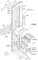
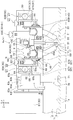
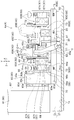
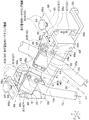
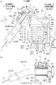
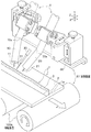
- Embodiment 1 of the welding apparatus which concerns on this invention. It is a schematic perspective view which shows the head unit apparatus of Embodiment 1 of the welding apparatus which concerns on this invention. It is a schematic plan view of the welding head part of Embodiment 1 of the welding apparatus which concerns on this invention. It is a schematic right view of the welding head part of Embodiment 1 of the welding apparatus which concerns on this invention. It is a schematic perspective view of the welding head part of Embodiment 1 of the welding apparatus which concerns on this invention. It is a schematic front view which shows the vertical positioning mechanism of Embodiment 1 of the welding apparatus which concerns on this invention.
- FIG. 1 It is a schematic front view which shows the horizontal positioning mechanism of Embodiment 1 of the welding apparatus which concerns on this invention. It is a figure which shows the angle adjustment mechanism of Embodiment 1 of the welding apparatus which concerns on this invention, (a) is a schematic perspective view, (b) is a longitudinal cross-sectional view of a torch clamp. It is a figure which shows the clamp mechanism for filler wire torches and filler wire torch position adjustment mechanism of Embodiment 1 of the welding apparatus which concerns on this invention, (a) The schematic perspective view seen from the front direction, (b) is seen from the back direction. FIG. It is a schematic side view which shows the torch support mechanism for filler wires of Embodiment 1 of the welding apparatus which concerns on this invention.
- Embodiment 1 of the welding apparatus which concerns on this invention is shown, (a) is a top view, (b) is a schematic longitudinal cross-sectional view. It is a figure which shows Embodiment 2 of the welding apparatus which concerns on this invention, and is a schematic principal part perspective view which shows the state when welding, moving a to-be-welded member with a moving apparatus.
- FIGS. 1 and 2 in the present embodiment, first, as an example of the welding apparatus S, a lower plate 2 that is installed horizontally, and a standing plate 3 that is arranged perpendicularly to the upper surface of the lower plate 2, An example of a so-called line welder in which fillet welding is performed while moving the welding head portion 4 (welder, see FIG. 2) with the moving device 100 along the welded portion 1a at the corner of the member 1 to be welded.
- the X direction is a butt direction that is a horizontal direction orthogonal to the welding direction
- the Y direction is a vertical direction that is a vertical up and down direction
- the Z direction is a welding direction.
- the welding apparatus S welds the lower plate 2 and the standing plate 3 which are the members 1 to be welded, moving the welding head part 4 along the to-be-welded location 1a (welding line).
- This is a gas shielded arc welding apparatus.
- the welding device S includes a moving device 100, a control panel 400, an operation panel 410, a dust collector 500, a wire container 600, a welding power source, a cooling water supply device, a shield gas supply device (not shown), and welding.
- a head unit 4 (welder).
- the member to be welded 1 is a large structure or the like used for, for example, a ship or a bridge, and includes a lower plate 2 and a standing plate 3, for example.
- This member 1 to be welded is welded and joined to the lower plate 2 and the upright plate 3 so as to be orthogonal to each other.
- a welding head portion 4 (see FIG. 2), which will be described later, is disposed on the welded portion 1a (welding line) to be welded, and the welding head portion 4 is moved along the welded portion 1a by the welding direction moving device 110. Run.
- the moving device 100 travels to move the welding head portion 4 (welder) in the welding direction (Z direction), the butting direction (X direction orthogonal to the welding direction), and the vertical direction (Y direction).
- the moving device 100 includes, for example, a welding direction moving device 110 (see FIG. 1), a head unit device 200, a vertical movement cylinder 270, and a welding head portion moving device 80.
- a welding direction moving device 110 shown in FIG. 1 is a conveying device that moves a number of welding head portions 4 (see FIG. 2) of the welding device S arranged on the back side thereof in the welding direction.
- the welding direction moving device 110 includes a pair of rails 150, a traveling roller 120, a traveling motor 130, and a gantry frame 140.
- the welding direction moving device 110 rotates the traveling motor 130 so that each welding head unit 4 moves in the welding direction together with the base 50 to perform welding.
- the rails 150 are a pair of left and right traveling guide rails made of, for example, I-shaped steel, and are installed along the plurality of welded members 1 laid on the floor surface of the welding facility.
- the running roller 120 is a wheel that moves the gantry frame 140 in the welding direction by rolling on each rail 150, and a plurality of the running rollers 120 are arranged at the lower end of the gantry frame 140.
- the travel motor 130 is a drive source that rotationally drives each travel roller 120, and is driven by a current supplied from a power source (not shown) via the control panel 400, with a deceleration transmission mechanism (not shown) interposed. The traveling roller 120 is driven to rotate.
- the gantry frame 140 includes, for example, a gate-type frame disposed so as to straddle the member 1 to be welded, and includes a pair of left and right vertical leg portions 141 and a deck 142 mounted on the left and right leg portions 141. I have. On the gantry frame 140, a traveling roller 120, a traveling motor 130, a head unit device 200, a control panel 400, a dust collector 500, a wire container 600, and the like are mounted.
- the head unit device 200 is an arch-shaped device for moving the welding head portion 4 in the butting direction, and is provided along the gantry frame 140 (see FIG. 1), for example.
- the head unit device 200 includes a stanchion 210 (see FIG. 1), a lateral guide 220, a sliding plate 230, a fixed frame 240, a vertical motion frame 250, a head unit lateral motion motor 260, A vertical movement cylinder 270, a right welding head portion vertical movement cylinder 81, a left welding head portion vertical movement cylinder 82, and an operation panel 410 are provided.
- the stanchion 210 is an arch-shaped column frame that suspends a wire container 600 that accommodates a welding wire serving as a leading electrode 11 (see FIG. 2) and a trailing electrode 21.
- the stanchion 210 includes a column frame 211, a construction frame 212, and a hanging tool 213.
- the column frame 211 is a pair of left and right column members that stand on the gantry frame 140 and move together.
- the erection frame 212 is a member on which a large number of suspenders 213 are suspended at an appropriate interval, and is erected at the upper end portion between the two column frames 211.
- the hanging tool 213 is a member for hanging the wire container 600 and is suspended by the erection frame 212.
- the lateral guide 220 is a frame member that extends from the deck 142 in the left-right direction, and has a pair of travel guide portions 220 a that extend in the butting direction.
- the lateral guide 220 is installed on the stanchion 210 in the abutting direction.
- the sliding plate 230 is a member that slides in the abutting direction while being guided by the traveling guide portion 220a, and has an engaging portion (not shown) that engages with the traveling guide portion 220a.
- the sliding plate 230 is provided on the lateral guide 220 so as to be slidable in the lateral direction.
- the fixed frame 240 is a frame-like frame extending in the vertical direction, and is fixed to the sliding plate 230 and provided to move up and down by a vertical movement cylinder 270.
- the vertical movement frame 250 is a frame for holding the welding head portion 4 and the operation panel 410, and is provided to move up and down with respect to the fixed frame 240 by the vertical movement cylinder 270. .
- the vertical movement frame 250 is formed of a rectangular frame-like frame extending in the vertical direction like the fixed frame 240, and is disposed opposite to the fixed frame 240.
- a welding head moving device 80 for moving the base 50 in the X, Y, and Z directions is provided between the vertically moving frame 250 and the welding head 4.
- the right-side welding head portion 4 will be described below, and the description on the left side will be omitted as appropriate.
- the head unit lateral movement motor 260 is a motor driving device for running the fixed frame 240 and moving the left and right welding head portions 4 in the horizontal direction, and is provided on the fixed frame 240.
- the vertically moving cylinder 270 is a device that moves the vertically moving frame 250 up and down with respect to the lateral guide 220 and the sliding plate 230 via the vertical guide 280 on the fixed frame 240, and includes, for example, an air cylinder device.
- the cylinder 270 for vertical movement is provided with a cylinder 271 connected to the lower center of the upper end of the frame-shaped vertical movement frame 250, an upper end is provided in the cylinder 271 so as to be movable up and down, and a lower end is fixed to the sliding plate 230.
- the welding head unit moving device 80 has a welding head unit 4 more than the welding direction moving device 110 (see FIG. 1), the head unit device 200 (see FIG. 1), and the vertical movement cylinder 270. It is an apparatus for adjusting the position of the welding head portion 4 by moving a short distance in the X, Y, and Z directions.
- the welding head portion moving device 80 includes a right welding head portion vertical movement cylinder 81, a left welding head portion vertical movement cylinder 82, and a butt air cylinder 83.
- the right welding head portion vertical movement cylinder 81 is a device for moving the right welding head portion 4 disposed on the right side of the vertical movement frame 250 in the vertical direction (Y direction), and is rectangular.
- the frame is fixed to the right frame of the vertically moving frame 250.
- the cylinder 82 for vertical movement of the left welding head part is a cylinder device for moving the left welding head part 4 arranged on the left side of the vertical movement frame 250 in the vertical direction (Y direction). It is fixed to the left frame of the frame 250.
- the butting air cylinder 83 (butting direction moving device) is a device that moves the entire welding head part 4 together with the base 50 in the butting direction (X direction).
- the abutting air cylinder 83 is fixed to the base 50 and is moved forward and backward by compressed air supplied to the inside, and a piston having one end portion disposed in the cylinder 83a and the other end fixed to the connecting frame 83c.
- the rod 83b, the connecting frame 83c connected to the vertical movement frame 250, a pair of upper and lower sliders 83d extending in the butting direction on the side surface on the welding direction side of the cylinder 83a, and the slider 83d are slidable.
- a guide rail 83e for guiding the movement of the cylinder 83a in the butting direction
- a holding plate 83f for fixing the guide rail 83e to the side surface of the right welding head portion vertical movement cylinder 81.
- the operation panel 410 operates the head unit lateral movement motor 260, the vertical movement cylinder 270, the welding head moving device 80, the welding power source, the cooling water supply device, and the shield gas supply device (not shown) to operate the left and right welding head portions.
- 4 is a controller for controlling the position and drive of 4, and is attached to the vertically moving frame 250.
- a power source includes a welding power source (power feeding device) that supplies power to each electrode portion of the leading electrode 11 and the trailing electrode 21 of the welding device S shown in FIG. 2 and a traveling motor 130 (see FIG. 1). And a power source that supplies electric power to the drive source of the head unit lateral movement motor 260, and is installed at a predetermined position, for example, under the floor of the welding direction moving device 110. The same applies to a cooling water supply device (not shown) and a shield gas supply device.
- the welding head 4 (welding machine) supports the leading electrode torch 10, the trailing electrode torch 20, the filler wire torch 30, and these torches (10, 20, 30), respectively.
- Torch clamp mechanism 40 a welding power source (not shown) for supplying current to those torches (10, 20, 30), a base 50 on which these torches (10, 20, 30) are supported, and a base
- a welding head part moving device 80 for moving the welding head part 4 such as 50.
- the entire welding head portion 4 can be largely moved in the X, Y, and Z directions by the welding direction moving device 110 (see FIG. 1), the head unit device 200, and the vertical movement cylinder 270.
- the position adjusting mechanism 60 can move the leading electrode torch 10, the trailing electrode torch 20, and the filler wire torch 30 small in the X, Y, and Z directions. It has become.
- This welding head part 4 performs gas shielded arc welding while running with the welding direction moving device 110, and supplies a current to the torch (10, 20, 30) or injects an inert gas. Since the configuration of the known gas shielded arc welding apparatus is used, detailed description thereof is omitted.
- each welding head portion 4 in which each torch (10, 20, 30) is arranged is configured such that the leading electrode 11, the trailing electrode 21 and the filler wire 31 are fed.
- the position and angle in the X, Y, and Z directions are provided on the base 50 via a torch clamp mechanism 40 having an angle adjustment mechanism 44 and a position adjustment mechanism 60 so as to be finely adjusted.
- the bent portions 10a, 20a are curved from the support portion supported by each torch clamp 45 toward the tip of the electrode torch (10, 20). It consists of a curved torch formed, and it is possible to easily adjust the advancing angle and the receding angle with respect to the welded portion 1a (see FIG. 4) by loosening each torch clamp 45 and adjusting the rotation around the axis. is there.
- the torch clamp mechanism 40 is a support mechanism for supporting the leading electrode torch 10, the trailing electrode torch 20, and the filler wire torch 30.
- the torch clamping mechanism 40 A and the trailing electrode torch 20 It comprises a supporting electrode torch clamp mechanism 40B for supporting and a filler wire torch clamping mechanism 40C for supporting the filler wire torch 30. Since the torch clamp mechanism 40A for the leading electrode and the torch clamp mechanism 40B for the trailing electrode are symmetrical, the leading torch clamp mechanism 40A for the leading electrode is mainly described, and the torch clamping mechanism 40B for the trailing electrode is described. Are omitted as appropriate.
- the leading electrode torch clamp mechanism 40 ⁇ / b> A is a support mechanism that detachably supports the leading electrode torch 10.
- each torch clamp 45 is a member that supports the leading electrode torch 10 and the trailing electrode torch 20, respectively.
- Each torch clamp 45 is formed with a holding hole 45a, a notch groove 45b, a screw hole 45c, a protruding piece 45d, and a fixed female screw portion 45e.
- the holding hole 45a is a hole into which each of the torches (10, 20) is inserted so as to be rotatable in the circumferential direction via the insulating bush 9, and the notch groove 45b is formed on the outer periphery, so that the holding hole 45a is viewed in plan view. It is formed in a substantially C shape.
- the notch groove 45b is a part that is notched from the outer periphery of the torch clamp 45 to the holding hole 45a, and is formed by arranging a pair of projecting pieces 45d at a predetermined gap interval.
- the screw hole 45c is a hole into which a fastening member T1 for adjusting the tightening condition formed orthogonally to the notch groove 45b is screwed.
- the diameter of the holding hole 45a and the interval between the notch grooves 45b between the pair of projecting pieces 45d are adjusted, and the holding hole 45a that holds the leading electrode torch 10 is held. It is formed on the projecting piece 45d so that the tightening force is adjusted.
- the projecting piece 45d is formed of a pair of thick plate-like members in which a notch groove 45b and a screw hole 45c are formed. If the fastening member T1 is strongly screwed into the screw hole 45c, the protrusion 45d has a narrow space between the protrusions 45d and 45d, and the torsion clamp 45 tightens the tightening force for fastening the leading electrode torch 10.
- the torch clamp 45 is firmly clamped. If the fastening member T1 is loosened, the inner diameter of the holding hole 45a becomes weaker to tighten the leading electrode torch 10, and the leading electrode torch 10 is circumferentially centered on the center line of the holding hole 45a (in the direction of arrow b). ) Or by moving forward and backward in the direction of the center line (in the direction of arrow a), it is possible to adjust the length of protrusion of the leading electrode torch 10 from the torch clamp 45, or to pull it out.
- the fixed female screw portion 45e is a portion into which the male screw portion at the tip of the torch clamp support 48 that the torch clamp mounting stay 46 fixes to the torch clamp 45 is screwed.
- the torch clamp mounting stay 46 is a support plate member for supporting the torch clamp 45 so as to be rotatable by the length in the circumferential direction of the arc-shaped long hole 46b centering on the support shaft member insertion hole 46a. Next to the clamp 45. The lower end of the torch clamp mounting stay 46 is connected to the slider 67 by the fastening member T2, and both can move in the X and Y directions.
- the support shaft member 47 is threaded into the fixed female thread portion 45e of the torch clamp 45 by inserting the torch clamp support 48 through the adjustment hole 49a that is long in the vertical direction of the attachment 49, and the torch clamp 45 is attached to the torch clamp mounting stay 46.
- This is a screw member that allows the torch clamp 45 to rotate about the support shaft member 47 when it is rotatable.
- the support shaft member 47 is inserted into a support shaft member insertion hole 46 a formed in the torch clamp mounting stay 46.
- the torch clamp support 48 is a screw member whose tip is screwed to the fixed female screw portion 45e via the adjustment hole 49a and the arc-shaped elongated hole 46b, and a pair of left and right for restricting the rotation of the torch clamp 45. It is a member.
- the pair of torch clamp supports 48 are inserted into arc-shaped elongated holes 46 b formed in the torch clamp mounting stay 46.
- the metal plate 49 is a metal thick plate member having a pair of left and right adjustment holes 49a that are long in the vertical direction in which the two torch clamp support tools 48 are inserted, and is arranged so as to cover the arc-shaped long hole 46b.
- the fastening member T1 is an adjustment screw member that adjusts the clearance between the cutout grooves 45b and adjusts the tightening force of the torch clamp 45 by the holding hole 45a, and includes, for example, two screw members.
- the angle adjusting mechanism 44 is a mechanism that adjusts the installation angle of the leading electrode torch 10 by rotating the leading electrode torch 10 by a predetermined angle.
- the angle adjusting mechanism 44 is capable of adjusting the vertical direction of the leading electrode 11 by pivotally supporting the leading electrode torch 10 so as to be rotatable in the vertical direction (Y direction) about the support shaft member 47.
- the angle adjusting mechanism 44 is connected to the torch clamp 45 adjacent to the torch clamp mounting stay 46, the support shaft member 47 inserted into the support shaft member insertion hole 46a formed in the torch clamp mounting stay 46, and the torch clamp mounting stay.
- the support shaft member 47 and the torch clamp support 48 constitute an angle adjustment mechanism 44 that adjusts the angle in the vertical direction of the leading electrode 11 by loosening the tightening degree fastened to the torch clamp 45.
- the angle adjusting mechanism 44 is similar to the angle adjusting mechanism 44 using an arc-shaped elongated hole in the filler wire torch clamping mechanism 40 ⁇ / b> C of the filler wire torch 30. Is provided. Therefore, the description thereof is omitted.
- the position adjustment mechanism 60 moves the leading electrode torch 10, the trailing electrode torch 20, and the filler wire torch 30 (see FIG. 9) in the butting direction and the vertical direction, respectively.
- the position adjusting mechanism 60 includes a leading electrode torch position adjusting mechanism 60A that adjusts the position of the leading electrode torch 10, a trailing electrode torch position adjusting mechanism 60B that adjusts the position of the trailing electrode torch 20, and a filler wire torch. And a filler wire torch position adjusting mechanism 60 ⁇ / b> C for adjusting the position of 30.
- the leading electrode torch position adjusting mechanism 60A, the trailing electrode torch position adjusting mechanism 60B, and the filler wire torch position adjusting mechanism 60C can adjust the position by moving the torch clamps 45 and 45C in the vertical direction (Y direction), respectively.
- the vertical positioning mechanism 61 of the leading electrode torch position adjusting mechanism 60A includes a knob 64, a feed screw member 65, a fixed base 66, and a slider 67, which will be described later. (Vertical slider portion 67Y) and a fastening member T5.
- Each torch (10, 20, 30) is moved by the vertical positioning mechanism 61 by moving the vertical slider portion 67Y in the vertical direction (Y direction) through the feed screw member 65 by rotating the knob 64.
- the horizontal slider portion 67X, the torch clamp mounting stay 46, the torch clamp 45, and each torch (10, 20, 30) are integrated with the left and right guide portions 69a of the horizontal positioning mechanism 62 connected to the vertical slider portion 67Y in the vertical direction. It can be moved and adjusted in the vertical direction.
- the knob 64 is a rotary operation knob for finely moving the leading electrode torch 10 in the vertical direction with respect to the base 50.
- the feed screw member 65 is a screw rod-like member that rotates integrally by rotating the knob 64, and the vertical slider portion 67 ⁇ / b> Y is screwed forward and backward at the center portion, and the base end portion is an upper and lower guide of the fixed base 66.
- the portion 66a is cantilevered so as to be rotatable.
- the fixed base 66 is a member having a substantially grooved steel shape when viewed from the front and having an upper and lower guide portion 66a (support plate portion), and the fastener T3 inserted into the long hole 50a of the base 50 is connected to the upper and lower guide portions 66a. It is fixed on the base 50 by being screwed into a female screw portion 66d formed on the lower plate portion.
- the fixed base 66 is provided with a pair of left and right guide shafts 66c that are inserted into the vertical slider portion 67Y and slidably support the vertical slider portion 67Y.
- the slider 67 has a female screw portion 67Yb that is screwed into a male screw portion 65a formed on the feed screw member 65, and is a member that slides between the upper and lower guide portions 66a and 66a as the feed screw member 65 rotates.
- the slider 67 is formed by connecting a vertical slider portion 67Y that can move in the vertical direction and a guide member 69 that supports a horizontal slider portion 67X (see FIG. 7) that can move in the butting direction by a fastening member T5. It moves together with the fixed base 66 in the vertical direction.
- the fastener T3 is a bolt for position adjustment of a welding direction position adjustment mechanism 60D described later.
- the fastening member T5 is a bolt for fixing the guide member 69 of the horizontal positioning mechanism 62 to the vertical slider portion 67Y of the vertical positioning mechanism 61.
- the horizontal positioning mechanism 62 of the leading electrode torch position adjusting mechanism 60A includes a knob 63, a feed screw member 68, a horizontal slider portion 67X of the slider 67, and a guide member which will be described later. 69 and the fastening member T2.
- Each torch (10, 20, 30) is moved by the horizontal positioning mechanism 62 by moving the horizontal slider portion 67X in the butting direction (X direction) via the feed screw member 68 by rotating the knob 63.
- the torch clamp 45 and the torches (10, 20, 30) together with the torch clamp mounting stay 46 connected to the horizontal slider portion 67X can be moved integrally with respect to the abutting direction, and the movement can be adjusted in the abutting direction. ing.
- the knob 63 is a rotary operation knob for finely moving the leading electrode torch 10 in the abutting direction with respect to the base 50.
- the feed screw member 68 is a screw rod-like member that rotates integrally when the knob 63 is rotated.
- the horizontal slider portion 67X is screwed into the central portion so as to be able to advance and retract.
- the portion 69a is cantilevered so as to be rotatable.
- the horizontal slider portion 67X of the slider 67 includes a left and right guide portion 69a that rotatably supports the feed screw member 68, and a female screw portion 67Xb that is screwed into a male screw portion 68a formed on the feed screw member 68.
- the guide member 69 is a member having a substantially grooved steel shape in plan view, and a pair of upper and lower guide shafts 69c that are inserted through the horizontal slider portion 67X and slidably support the horizontal slider portion 67X are installed. is doing.
- the fastening members T5 are screwed into the four counterbore holes formed from the inner inner wall surface of the guide member 69 toward the vertical slider portion 67Y.
- the bolts are tightened so as to be in contact with the side surfaces of the vertical slider portion 67Y.
- the fastening member T ⁇ b> 2 is a bolt that is screwed into the slider 67 from the side surface of the torch clamp mounting stay 46 and connects the torch clamp mounting stay 46 and the slider 67.
- the filler wire torch 30 shown in FIGS. 9 to 10 includes a filler wire torch clamp mechanism 40C substantially the same as the preceding electrode torch clamp mechanism 40A provided on the preceding electrode torch 10 as described above, and an angle.
- An adjustment mechanism 44 is provided.
- the filler wire torch position adjusting mechanism 60C moves the filler wire torch 30 in the horizontal butting direction (arrow c). It has a horizontal positioning mechanism 61C that adjusts the position of the torch (30), but is not provided with a mechanism corresponding to the vertical positioning mechanism 61. That is, the filler wire torch position adjusting mechanism 60C moves the torch clamp 45C in the butting direction (arrow c direction) by sliding the slider 67C in the welding direction (Z direction) by rotating the knob 63C. It has a structure that can be done.
- the filler wire torch position adjusting mechanism 60C includes a knob 63C, a feed screw member 65C, a fixing base 66C, and a slider 67C, and is disposed on the base 50, like the preceding electrode torch position adjusting mechanism 60A.
- the filler wire torch position adjusting mechanism 60C can also adjust the height in the vertical direction by interposing a spacer (not shown) with an appropriate thickness between the base 50 and the fixed base 66C. is there.
- the number of knobs 63C for moving the filler wire torch 30 is one.
- the feed screw member 65C is supported by a support plate portion 66Ca provided on the fixed base 66C and is disposed horizontally with respect to the base 50.
- the fixed base 66C has a support plate portion 66Ca that holds both ends of the guide shaft 66c extending in the butting direction (X direction), and a sliding surface 66Ce on which the slider 67C slides.
- This is a member having a substantially groove-shaped steel shape, and is bolted to a predetermined position on the base 50.
- the slider 67C slides on the horizontal sliding surface 66Ce in the horizontal direction (arrow c direction) in accordance with the rotation of the feed screw member 65C by the turning operation of the knob 63C, and moves the torch clamp 45C in the butting direction (X direction). ).
- the base 50 is used to place the fixed bases 66 and 66C of the leading electrode torch position adjusting mechanism 60A, the trailing electrode torch position adjusting mechanism 60B, and the filler wire torch position adjusting mechanism 60C at predetermined positions.
- a long hole 50a (FIG. 2) into which a fastener T3 of a welding direction position adjusting mechanism 60D for fixing the fixing bases 66 and 66C to a predetermined position in the welding direction is movably inserted along the plate surface of the base 50.
- a plurality of reference are formed.
- the base 50 includes the right welding head portion vertical movement cylinder 81 (lifting device) (see FIG.
- the welding direction position adjusting mechanism 60D moves the fixed bases 66 and 66C placed on the base 50 horizontally in the welding direction, thereby leading the torch 10 for the leading electrode, the torch 20 for the trailing electrode, and the filler.
- the position of the wire torch 30 is adjusted and fixed to a predetermined position in each welding direction.
- the welding direction position adjusting mechanism 60D is configured so that the internal thread portion 66d formed in the fixing bases 66 and 66C, the long hole 50a formed long in the welding direction in the base 50, and the long hole 50a can be finely adjusted in the welding direction.
- a position adjusting fastener T3 that is movably inserted and screwed into the female thread portions 66d and 66Cd (see FIG. 10) of the fixing bases 66 and 66C to fix the fixing bases 66 and 66C at predetermined positions. It is configured.
- the positioning dog portion 70 has a horizontal position and a vertical position of the electrode torch (10, 20) and the filler wire torch 30 mounted on the base 50 with respect to the welded member 1. This is a device for accurately copying.
- the positioning dog portion 70 is moved together with the base 50 by a right welding head portion vertical movement cylinder 81 (see FIG. 2) (lifting device) and a butt air cylinder 83 (butting direction moving device) that moves the base 50 in the butting direction. The position can be adjusted.
- the positioning dog part 70 can judge the distance of a butt
- the positioning dog portion 70 is formed of a substantially square thick plate shape fixed to the lower surface of the base 50 with a fastening member T4.
- the positioning dog part 70 is a long member 71 fixed to the base 50 in a horizontal state.
- the operation of the welding apparatus S will be described with reference to FIGS.
- the lower plate 2 of the member to be welded 1 is arranged along the rail 150 between the leg portions 141 and 141 of the gantry frame 140, and the lower plate 2
- the standing plate 3 is placed and fixed at a predetermined position above.
- the welding head part 4 shown in FIG. 2 is sent to the vicinity of the upper part of the welded portion 1a by the head unit device 200.
- the welding head part 4 is sent to the height vicinity of the to-be-welded location 1a with the cylinder 270 for a vertical motion.
- the fastening member T1 of the torch clamp 45 shown in FIGS. 8A and 8B is once loosened, and the axial direction of the leading electrode torch 10 (the trailing electrode torch 20) with respect to the welded portion 1a of the member 1 to be welded ( The positions in the direction of arrow a) and the direction around the axis (direction of arrow b) are adjusted.
- the leading electrode torch 10 is a curved torch formed by bending or bending the bent portion 10a. Therefore, if the torch is rotated, the leading electrode 11 becomes the center of the holding hole 45a. It is possible to adjust the advancing angle and the receding angle of the preceding electrode 11 with respect to the welded portion 1a by rotating in the direction around the axis (in the direction of arrow b) around the line.
- the support shaft member 47 and the torch clamp support 48 of the torch clamp 45 are once loosened, and the vertical direction (Y of the leading electrode torch 10 (the trailing electrode torch 20) with respect to the welded portion 1a of the welded member 1 is determined. (Direction) is adjusted to an appropriate angle.
- the horizontal slider 67X that moves integrally with the torch clamp 45 is abutted by rotating the knob 63 of the horizontal positioning mechanism 62 to rotate the feed screw member 68.
- the position of the leading electrode torch 10 in the butting direction (X direction) is finely adjusted.
- the vertical slider portion 67Y that moves integrally with the torch clamp 45 is moved in the vertical direction.
- the position in the vertical direction of the leading electrode torch 10 is finely adjusted by moving in the (Y direction). In the same manner, the position of the trailing electrode torch 20 in the vertical direction and the butting direction is finely adjusted.
- the filler wire torch 30 rotates the feed screw member 65C by rotating the knob 63C, thereby causing the slider 67C moving integrally with the torch clamp 45C to abut the direction.
- the position of the filler wire torch 30 in the horizontal direction is finely adjusted by moving in the direction of arrow c.
- the welding apparatus S includes the knobs 63 and 64 of the vertical positioning mechanism 61 and the horizontal positioning mechanism 62, the knob 63 of the filler wire torch position adjusting mechanism 60C, the fastener T3 of the welding direction position adjusting mechanism 60D, and the angle adjusting mechanism.
- each torch (10, 20, 30) can be moved in all directions including the welding direction, the vertical direction, and the butting direction in the vertical and horizontal directions. It can be rotated in the direction. This makes it possible to easily optimize the distance between the electrodes of each torch (10, 20, 30) and the torch angle, even if the device includes filler wires 31 on a plurality of electrodes.
- the welding conditions can be adjusted.
- the knobs 63, 64, and 63C are easy to rotate, the positions of the torches (10, 20, and 30) are easily adjusted to optimum welding conditions even when the welding operation is started and during the welding operation. be able to. As a result, when welding the member 1 to be welded, a good bead can be formed, and the stability of the generated arc can be improved and the occurrence of spatter can be suppressed.
- each torch (10, 20, 30) is positioned at an appropriate position, angle, and orientation as described above, and the welding head portion 4 is welded to the welded portion 1a of the member 1 to be welded by the welding direction moving device 110. It can be made to drive
- FIG. 12 is a diagram showing a second embodiment of the welding apparatus according to the present invention, and is a schematic perspective view showing a main part when welding a member to be welded while moving it with a moving device.
- the welding apparatus S that welds the welded member 1 while moving the welding head portion 4 (welder) with the moving apparatus 100 has been described, but the present invention is limited to this. Is not to be done.
- the welding apparatus S1 is of a built-up type in which welding is performed while moving the member to be welded 1 with respect to the base 50 of the welding head portion 4 by the moving apparatus 100A. It doesn't matter.
- the torch support mechanisms 60A, 60B, and 60C do not have to be on the base 50, and may be directly attached to any part of the moving device 100A.
- Embodiment 1 and 2 which concern on this invention were demonstrated, this invention is not limited to above-described Embodiment 1, 2, and can be suitably changed in the range which does not deviate from the meaning of this invention. .
- the already demonstrated structure attaches
- the welding apparatus S was mentioned as an example in the case of welding the to-be-welded member 1 arrange
- the shape and material of the member 1 to be welded are not particularly limited.
- the torch clamp mechanism 40A for the leading electrode, the torch clamp mechanism 40B for the trailing electrode, and the clamp mechanism 40C for the filler wire torch are configured with members having different shapes. It doesn't matter. Further, the leading electrode torch position adjusting mechanism 60A, the trailing electrode torch position adjusting mechanism 60B, and the filler wire torch position adjusting mechanism 60C are configured by members having different shapes, but may be the same. The leading electrode torch 10 and the trailing electrode torch 20 may be plural by adding the leading electrode 11 and the trailing electrode 21 respectively. Further, the filler wire torch 30 may have a plurality of filler wires 31. Further, the filler wire torch may or may not be energized. Furthermore, as long as fine adjustment is possible, the shape of the filler wire torch may be a straight torch having the same specifications as the electrode torch.
- the parts that support the torches (10, 20, 30) of the torch clamps 45, 45C are provided with anti-loosening members such as spring washers, non-rotating wires, knock pins, split pins, etc. so that they can be held firmly for a long time. Also good.
Landscapes
- Engineering & Computer Science (AREA)
- Physics & Mathematics (AREA)
- Mechanical Engineering (AREA)
- Plasma & Fusion (AREA)
- Optics & Photonics (AREA)
- Arc Welding In General (AREA)
- Butt Welding And Welding Of Specific Article (AREA)
Abstract
容易にトーチの位置を調整することができるガスシールドアーク溶接装置Sは、電極を有する電極用トーチ(10,20)と、フィラーワイヤ31を支持するフィラーワイヤ用トーチ30と、電極用トーチ(10,20)、フィラーワイヤ用トーチ30をそれぞれ支持する各トーチクランプ45と、各トーチクランプ45が支持されるベース50と、ベース50を移動させる移動装置(100)とを有する。溶接装置Sは、電極用トーチ(10,20)及びフィラーワイヤ用トーチ30をそれぞれ所定角度回動させて電極用トーチ(10,20)及びフィラーワイヤ用トーチ30の設置角度をそれぞれ調整する各角度調整機構44と、電極用トーチ(10,20)及びフィラーワイヤ用トーチ30を全方向へ移動させて電極用トーチ(10,20)、フィラーワイヤ用トーチ30の位置をそれぞれ位置調整する各位置調整機構60とを有する。
Description
本発明は、電極用トーチとフィラーワイヤ用トーチとを備えたガスシールドアーク溶接装置に関する。
造船や橋梁等で使用する長尺な鋼材を水平すみ肉溶接する際には、立板の両側にそれぞれ二つの電極を配置し、これらの電極で一つの溶融プールを形成して溶接する二電極式のガスシールドアーク溶接が知られている(例えば、特許文献1参照)。
この二電極式のガスシールドアーク溶接は、溶接電流を大きくし、溶接速度を高速にすることにより、立板の両側にそれぞれ一つの電極を配置した溶接法と比較して二倍以上の高速溶接が可能となる。
しかしながら、電極の電流値を所定値以上に高くすると、先行極及び後行極の溶接電流による磁界の影響によって、二極間でのアーク干渉が激しくなる。
このため、二電極式のガスシールドアーク溶接では、溶接中の溶融プール形状の変動が大きくなり、溶接不良が発生するという問題があった。
しかしながら、電極の電流値を所定値以上に高くすると、先行極及び後行極の溶接電流による磁界の影響によって、二極間でのアーク干渉が激しくなる。
このため、二電極式のガスシールドアーク溶接では、溶接中の溶融プール形状の変動が大きくなり、溶接不良が発生するという問題があった。
このような問題に対し、先行電極と後行電極との間に、その電極間の磁場を打ち消すためのフィラーワイヤを配置して溶接を行なうガスシールドアーク溶接方法が提案されている(例えば、特許文献2参照)。このような方法を用いることで、溶融プール形状の変動を抑え、溶接不良を大幅に低減することにより、手直しの必要がない溶接を実現することができる。
上記特許文献2のようなガスシールドアーク溶接方法を用いてより良好に被溶接部材を溶接する際には、特許文献3に記載されているような溶接条件に設定することが好ましい。この溶接条件に設定するためには、特許文献2に記載されている電極間距離、例えば、15~50mmという極めて狭い距離において、全てのトーチから送給されるそれぞれのワイヤ(以下ワイヤ先端)の間隔や角度を、可能な限り短時間において最適な条件に調整することを要求される。このような調整は、二電極の場合と比して極めて複雑な調整を要求される。
造船や橋梁メーカ等の生産ラインにおいて、実際にこのような要求を満足する溶接作業をする場合には、対象となる被溶接部材ごとに寸法が少しずつ異なること、送り位置が少しずれることなどにより、被溶接箇所が相違し、この相違により作業の都度ワイヤ先端の狙い位置が変わる。このため、溶接作業開始の度に全てのワイヤ先端の位置を毎回ミリメートル以下の単位で微調整することが必要であり、また、風による外乱等によって溶接条件が変化したり、作業の都度ワイヤ先端の狙い位置が変化するため、遮光ガラスを通してアーク状態を観察しながら電極の微調整を行う必要がある。
しかしながら、特許文献4に記載されているような自動溶接装置であって、前記特許文献3に記載されている溶接条件に設定する場合には、近接したトーチの中間にフィラーワイヤを挿入しただけの機構で被溶接部材ごとに前述のような最適な条件に設定しなければならず、適切に微調整を行うには作業者に相当な負担がかかる。また、失敗した場合には、手直しをしなければならず、生産性が大幅に低下する。このため、トーチの位置調整を可能な限り容易にできるようにしなければならないという問題があった。
そこで、本発明では、前記した問題点に鑑みてなされたものであって、複数電極にフィラーワイヤを備えた複雑な溶接条件、かつ、狭い電極間距離である機構であっても容易に最適な溶接条件にトーチの位置を調整することができるガスシールドアーク溶接装置を提供することを課題とする。
前記課題を解決するため、本発明に係るガスシールドアーク溶接装置は、給電装置から電流が供給される電極を有する複数の電極用トーチと、前記電極用トーチの間に配置され、フィラーワイヤを支持するフィラーワイヤ用トーチと、前記電極用トーチ及び前記フィラーワイヤ用トーチをそれぞれ支持するそれぞれのトーチクランプと、前記各トーチクランプが支持されるベースと、を備えたガスシールドアーク溶接装置であって、前記トーチクランプをそれぞれ所定角度回動させて前記電極用トーチ及び前記フィラーワイヤ用トーチの設置角度をそれぞれ調整するそれぞれの角度調整機構と、前記角度調整機構を全方向へ移動させて前記電極用トーチ及び前記フィラーワイヤ用トーチの位置をそれぞれ位置調整するそれぞれの位置調整機構と、を備えている構成とした。
ここで、全方向とは、溶接進行方向に直交する水平方向(以下「突合せ方向」または「X方向」という)と、鉛直な上下方向である垂直方向(以下適宜に「Y方向」という)と、溶接進行方向(以下「溶接方向」または「Z方向」という)と、を含む方向をいう。
ここで、全方向とは、溶接進行方向に直交する水平方向(以下「突合せ方向」または「X方向」という)と、鉛直な上下方向である垂直方向(以下適宜に「Y方向」という)と、溶接進行方向(以下「溶接方向」または「Z方向」という)と、を含む方向をいう。
かかる構成によれば、ガスシールドアーク溶接装置は、角度調整機構を有することによって、電極用トーチ及びフィラーワイヤ用トーチをそれぞれ所定角度回動させて電極用トーチ及びフィラーワイヤ用トーチのトーチ角度をそれぞれ適切な角度に微調整することができる。また、ガスシールドアーク溶接装置は、全方向へ移動させて位置調整することができる位置調整機構を有するトーチ支持機構によって支持されているので、被溶接部材の被溶接箇所に合わせてトーチの脚長を変更するときなどに、三電極以上の複数電極を有する複雑、かつ、狭い電極間距離の機構であっても、それぞれのトーチの位置を上下左右前後方向の全方向に自由に調整して、その先端の電極及びフィラーワイヤの位置を所定の狙い位置に容易に位置調整することができる。
また、前記位置調整機構は、前記各トーチクランプをそれぞれ垂直方向へ移動させて位置調整することができる垂直位置決め機構と、前記各トーチクランプをそれぞれ突合せ方向へ移動させて位置調整することができる水平位置決め機構と、を備えていることが好ましい。
かかる構成によれば、ガスシールドアーク溶接装置の位置調整機構は、垂直位置決め機構によってトーチ支持機構を垂直方向へ移動させて、電極の垂直方向の位置を調整することができると共に、水平位置決め機構によりトーチ支持機構を突合せ方向へ移動させて、電極の突合せ方向の位置を被溶接部材の被溶接箇所に合わせて調整することができる。このため、垂直位置決め機構と水平位置決め機構とによってそれぞれ容易に垂直方向及び突合せ方向の位置を調整することができるので、対象となる被溶接部材の被溶接箇所が変化しても直ぐに対処することができる。
また、前記垂直位置決め機構は、回転操作用のノブと、前記ノブに固定された送りねじ部材と、前記送りねじ部材が回転自在に挿入されて支持される支持板部を有し前記ベースに載置される固定台と、前記送りねじ部材に形成された雄ねじ部に螺合する雌ねじ部を有し、前記送りねじ部材の回転に伴って前記固定台に対してスライド移動すると共に、前記トーチクランプが連結されたスライダと、を備え、前記各トーチクランプは、前記ノブを回動させることによって前記スライダと共に垂直方向に移動することが好ましい。
かかる構成によれば、垂直位置決め機構は、ノブを回動させて送りねじ部材を連動回転させることによって、その回転に合わせて固定台及びベースに対してスライダ及びトーチ支持機構を連続的に移動させることができる。このため、電極の位置を垂直方向に微調整する必要がある場合には、ノブを回転操作すれば、電極及びフィラーワイヤの位置を被溶接部材の被溶接箇所に合わせて垂直方向に移動させて調整することができる。
また、前記水平位置決め機構は、回転操作用のノブと、前記ノブに固定された送りねじ部材と、前記送りねじ部材が回転自在に挿入されて支持される支持板部を有するガイド部材と、前記送りねじ部材に形成された雄ねじ部に螺合する雌ねじ部を有し、前記送りねじ部材の回転に伴って前記ガイド部材に対してスライド移動すると共に、前記トーチクランプが連結されたスライダと、を備え、前記各トーチクランプは、前記ノブを回動させることによって前記スライダと共に突合せ方向に移動することが好ましい。
かかる構成によれば、水平位置決め機構は、ノブを回動させて送りねじ部材を連動回転させることによって、その回転に合わせてベースに対してスライダ及びトーチ支持機構を連続的に移動させることができる。このため、電極の位置を突合せ方向に微調整する必要がある場合には、ノブを回転操作すれば、電極及びフィラーワイヤの位置を被溶接部材の被溶接箇所に合わせて突合せ方向に移動させて調整することができる。
また、前記ベースには、当該ベースに前記固定台を固定する締結具を当該ベースの板面に沿って溶接方向へ移動が可能となるように挿入させる長孔が形成されていることが好ましい。
かかる構成によれば、ベースは、このベースの板面の長孔に挿入された固定具の位置を移動させて調整することによって、固定台と共に移動する各トーチクランプ、電極及びフィラーワイヤの位置を溶接方向に微調整することができる。
また、前記角度調整機構は、前記トーチクランプに隣設されたトーチクランプ取付ステイと、前記トーチクランプ取付ステイに形成された支軸部材挿入孔に挿入される支軸部材と、前記トーチクランプ取付ステイに形成された円弧状長孔を挿通して前記トーチクランプに締結されるトーチクランプ支持具と、を備え、前記トーチクランプ支持具は、前記トーチクランプに締結される締付具合を緩めることによって、前記角度調整機構の垂直方向の角度を調整できるように設けられていることが好ましい。
かかる構成によれば、ガスシールドアーク溶接装置の角度調整機構は、電極用トーチ及びフィラーワイヤ用トーチをそれぞれ保持するトーチクランプに締結されるトーチクランプ支持具の締付具合を緩めることによって、トーチ支持機構の垂直方向の角度を円弧状長孔に沿って調整することができる。これにより、ガスシールドアーク溶接装置は、電極用トーチ及びフィラーワイヤ用トーチの垂直方向の角度を自由に調整してその向きを適切な向きに微調整することができる。
また、前記位置調整機構に取り付けられる前記電極用トーチは、前記各トーチクランプによって支持される支持部から当該電極用トーチの先端に向けてカーブして形成されたカーブドトーチからなり、前記各トーチクランプをそれぞれ緩めて軸回りに回動調整することで、被溶接箇所に対する前進角及び後退角が調整可能であることが好ましい。
かかる構成によれば、電極用トーチは、支持部から先端に向けてカーブして形成されたカーブドトーチからなることにより、各トーチクランプをそれぞれ緩めて軸回りに回動させれば、電極用トーチがトーチクランプに保持される支持部の中心線を中心として回動するため、被溶接箇所に対する電極用トーチの前進角及び後退角を適切な角度に自由に調整することが容易となる。
また、ガスシールドアーク溶接装置の各トーチクランプは、前記電極用カーブドトーチ、前記フィラーワイヤ用トーチをそれぞれ周方向に回動可能に挿入する保持孔と、前記保持孔に切欠形成された切欠溝と、前記切欠溝に直交して形成されたねじ孔と、前記ねじ孔に螺合され前記切欠溝の内壁の間隔を調整する締結部材と、を備え、前記締結部材は、前記ねじ孔の締付力を緩めることによって、前記電極用カーブドトーチ、前記フィラーワイヤ用トーチをそれぞれ周方向に回動可能にし、前記ねじ孔の締付力を強めることによって、前記電極用トーチ、前記フィラーワイヤ用トーチをそれぞれ保持することが好ましい。
かかる構成によれば、締結部材は、螺合されたねじ孔の締付力を緩めると、切欠溝の内壁の間隔が広がることに伴って、それぞれのトーチを保持する保持孔の内径が拡径するため、電極用トーチ、フィラーワイヤ用トーチをそれぞれ周方向に回動可能にすることができる。各トーチは、保持孔の中心線を中心として回動することにより、トーチの先端にある電極の向きを調整することができる。
また、締結部材は、ねじ孔の締付力を強めることによって、切欠溝の間隔が狭くなるのに伴って保持孔の内径が縮径するため、それぞれのトーチを強くしっかりと保持することができる。
また、締結部材は、ねじ孔の締付力を強めることによって、切欠溝の間隔が狭くなるのに伴って保持孔の内径が縮径するため、それぞれのトーチを強くしっかりと保持することができる。
また、前記ベースは、当該ベースを昇降させる昇降装置と、当該ベースを突合せ方向に移動させる突合せ方向移動装置と、当該ベースから突合せ方向に突出して配置され、前記電極用トーチ及び前記フィラーワイヤ用トーチの突合せ位置及び垂直位置を倣い決めする位置決めドグ(dog)部と、を備えていることが好ましい。
かかる構成によれば、ガスシールドアーク溶接装置は、位置決めドグ部が、昇降装置及び突合せ方向移動装置によってベースの位置を調整することにより、電極用トーチ及びフィラーワイヤ用トーチの突合せ位置及び垂直位置を被溶接箇所の位置に合せて倣い決めすることができる。このため、対象となる被溶接部材の被溶接箇所が変化しても容易に対処することができる。
また、ガスシールドアーク溶接装置は、前記ベースを、移動装置によって前記電極用トーチ、前記フィラーワイヤ用トーチと共に移動させながら溶接をすることが好ましい。
かかる構成によれば、ガスシールドアーク溶接装置は、ベースを移動装置によって溶接線に沿って移動させながら溶接をすることができる。
また、ガスシールドアーク溶接装置は、前記ベースに対して被溶接部材を、移動装置によって移動させながら溶接をすることが好ましい。
かかる構成によれば、ガスシールドアーク溶接装置は、被溶接部材を、移動装置によって移動させながら溶接をすることができる。
本発明のガスシールドアーク溶接装置によれば、電極用トーチ及びフィラーワイヤ用トーチを溶接方向、垂直方向、突合せ方向を含む全方向、かつ、所望の向きに回動させて、各トーチの電極間の極間距離や、トーチ角度を適切に調整することにより、複数電極にフィラーワイヤを備えた溶接装置であっても、容易に最適な溶接条件に調整することができる機構である。
この機構により、溶接作業開始時及び溶接作業中に容易に微調整して最適な溶接条件に設定することにより、良好な溶接ビードを形成することができると共に、発生するアークの安定性を向上させてスパッタの発生を抑制することができる。
また、トーチの位置等の微調整を行うための作業者の負担を極めて軽減することができる。
さらに、溶接不良に対する手直しという作業負担から解放され、生産性を大幅に向上させることができる。
この機構により、溶接作業開始時及び溶接作業中に容易に微調整して最適な溶接条件に設定することにより、良好な溶接ビードを形成することができると共に、発生するアークの安定性を向上させてスパッタの発生を抑制することができる。
また、トーチの位置等の微調整を行うための作業者の負担を極めて軽減することができる。
さらに、溶接不良に対する手直しという作業負担から解放され、生産性を大幅に向上させることができる。
[実施形態1]
本発明の実施形態について、適宜図面を参照しながら詳細に説明する。
図1及び図2に示すように、本実施形態では、まず、溶接装置Sの一例として水平に設置された下板2と、下板2の上面に垂直に配置された立板3と、からなる被溶接部材1の隅部を被溶接箇所1aに沿って移動装置100で溶接ヘッド部4(溶接機、図2参照)を移動させながらすみ肉溶接するいわゆるラインウェルダーの場合を例に挙げて説明する。
ここで、X方向は溶接方向に直交する水平方向である突合せ方向、Y方向は鉛直な上下方向である垂直方向、Z方向は溶接方向であり、以下、適宜に使用して説明する。
本発明の実施形態について、適宜図面を参照しながら詳細に説明する。
図1及び図2に示すように、本実施形態では、まず、溶接装置Sの一例として水平に設置された下板2と、下板2の上面に垂直に配置された立板3と、からなる被溶接部材1の隅部を被溶接箇所1aに沿って移動装置100で溶接ヘッド部4(溶接機、図2参照)を移動させながらすみ肉溶接するいわゆるラインウェルダーの場合を例に挙げて説明する。
ここで、X方向は溶接方向に直交する水平方向である突合せ方向、Y方向は鉛直な上下方向である垂直方向、Z方向は溶接方向であり、以下、適宜に使用して説明する。
≪溶接装置の構成≫
図1及び図2に示すように、溶接装置Sは、被溶接部材1である下板2と立板3とを被溶接箇所1a(溶接線)に沿って溶接ヘッド部4を移動させながら溶接するガスシールドアーク溶接装置である。溶接装置Sは、移動装置100と、制御盤400と、操作盤410と、集塵機500と、ワイヤ収容器600と、溶接用電源と冷却水供給装置とシールドガス供給装置(図示省略)と、溶接ヘッド部4(溶接機)と、を備えている。
図1及び図2に示すように、溶接装置Sは、被溶接部材1である下板2と立板3とを被溶接箇所1a(溶接線)に沿って溶接ヘッド部4を移動させながら溶接するガスシールドアーク溶接装置である。溶接装置Sは、移動装置100と、制御盤400と、操作盤410と、集塵機500と、ワイヤ収容器600と、溶接用電源と冷却水供給装置とシールドガス供給装置(図示省略)と、溶接ヘッド部4(溶接機)と、を備えている。
≪被溶接部材の構成≫
図1に示すように、被溶接部材1は、例えば、船舶や橋梁等に用いられる大型の構造物等であり、例えば、下板2と立板3とからなる。この被溶接部材1は、下板2と立板3とを直交するように突合された部位を溶接して接合される。その溶接される被溶接箇所1a(溶接線)の上には、後記する溶接ヘッド部4(図2参照)が配置され、溶接ヘッド部4が溶接方向移動装置110によって被溶接箇所1aに沿って走行する。
図1に示すように、被溶接部材1は、例えば、船舶や橋梁等に用いられる大型の構造物等であり、例えば、下板2と立板3とからなる。この被溶接部材1は、下板2と立板3とを直交するように突合された部位を溶接して接合される。その溶接される被溶接箇所1a(溶接線)の上には、後記する溶接ヘッド部4(図2参照)が配置され、溶接ヘッド部4が溶接方向移動装置110によって被溶接箇所1aに沿って走行する。
≪移動装置の構成≫
図2に示すように、移動装置100は、溶接ヘッド部4(溶接機)を溶接方向(Z方向)、突合せ方向(溶接方向に直交するX方向)、垂直方向(Y方向)へ移動させる走行装置である。移動装置100は、例えば、溶接方向移動装置110(図1参照)と、ヘッドユニット装置200と、上下動用シリンダ270と、溶接ヘッド部移動装置80と、を備えて構成されている。
図2に示すように、移動装置100は、溶接ヘッド部4(溶接機)を溶接方向(Z方向)、突合せ方向(溶接方向に直交するX方向)、垂直方向(Y方向)へ移動させる走行装置である。移動装置100は、例えば、溶接方向移動装置110(図1参照)と、ヘッドユニット装置200と、上下動用シリンダ270と、溶接ヘッド部移動装置80と、を備えて構成されている。
<溶接方向移動装置の構成>
図1に示す溶接方向移動装置110は、その背面側に配置された溶接装置Sの多数の溶接ヘッド部4(図2参照)を溶接方向へ移動させる搬送装置である。溶接方向移動装置110は、一対のレール150と、走行ローラ120と、走行モータ130と、架台フレーム140と、を備えている。溶接方向移動装置110は、走行モータ130を回転駆動させることによって、各溶接ヘッド部4がベース50と共に溶接方向に移動して溶接が行われる。
図1に示す溶接方向移動装置110は、その背面側に配置された溶接装置Sの多数の溶接ヘッド部4(図2参照)を溶接方向へ移動させる搬送装置である。溶接方向移動装置110は、一対のレール150と、走行ローラ120と、走行モータ130と、架台フレーム140と、を備えている。溶接方向移動装置110は、走行モータ130を回転駆動させることによって、各溶接ヘッド部4がベース50と共に溶接方向に移動して溶接が行われる。
レール150は、例えば、I型鋼からなる左右一対の走行ガイドレールであり、溶接施
設の床面に敷設された複数の被溶接部材1に沿って設置されている。
走行ローラ120は、各レール150上を転動することにより、架台フレーム140を溶接方向へ移動させる車輪であり、架台フレーム140の下端部に複数配置されている。
走行モータ130は、各走行ローラ120を回転駆動させる駆動源であり、制御盤400を介して電源(図示省略)から電流が供給されることで駆動し、不図示の減速伝達機構を介在して走行ローラ120を回転駆動させる。
架台フレーム140は、例えば、被溶接部材1を跨ぐように配置された門型フレームからなり、左右一対の垂直な脚部141と、左右の脚部141上に載設されたデッキ142と、を備えている。架台フレーム140には、走行ローラ120、走行モータ130、ヘッドユニット装置200、制御盤400、集塵機500、ワイヤ収容器600等が搭載されている。
設の床面に敷設された複数の被溶接部材1に沿って設置されている。
走行ローラ120は、各レール150上を転動することにより、架台フレーム140を溶接方向へ移動させる車輪であり、架台フレーム140の下端部に複数配置されている。
走行モータ130は、各走行ローラ120を回転駆動させる駆動源であり、制御盤400を介して電源(図示省略)から電流が供給されることで駆動し、不図示の減速伝達機構を介在して走行ローラ120を回転駆動させる。
架台フレーム140は、例えば、被溶接部材1を跨ぐように配置された門型フレームからなり、左右一対の垂直な脚部141と、左右の脚部141上に載設されたデッキ142と、を備えている。架台フレーム140には、走行ローラ120、走行モータ130、ヘッドユニット装置200、制御盤400、集塵機500、ワイヤ収容器600等が搭載されている。
<ヘッドユニット装置の構成>
図2に示すように、ヘッドユニット装置200は、溶接ヘッド部4を突合せ方向へ移動させるためのアーチ形状の装置であり、例えば、架台フレーム140(図1参照)に沿って設けられている。ヘッドユニット装置200には、スタンション(stanchion)210(図1参照)と、横方向ガイド220と、摺動板230と、固定フレーム240と、上下動フレーム250と、ヘッドユニット横動モータ260と、上下動用シリンダ270と、右溶接ヘッド部上下動用シリンダ81と、左溶接ヘッド部上下動用シリンダ82と、操作盤410と、が備えられている。
図2に示すように、ヘッドユニット装置200は、溶接ヘッド部4を突合せ方向へ移動させるためのアーチ形状の装置であり、例えば、架台フレーム140(図1参照)に沿って設けられている。ヘッドユニット装置200には、スタンション(stanchion)210(図1参照)と、横方向ガイド220と、摺動板230と、固定フレーム240と、上下動フレーム250と、ヘッドユニット横動モータ260と、上下動用シリンダ270と、右溶接ヘッド部上下動用シリンダ81と、左溶接ヘッド部上下動用シリンダ82と、操作盤410と、が備えられている。
図1に示すように、スタンション210は、先行電極11(図2参照)及び後行電極21となる溶接ワイヤを収納するワイヤ収容器600を移動自在に吊設するアーチ状の支柱フレームである。スタンション210は、柱フレーム211と、架設フレーム212と、吊具213と、を備えている。
柱フレーム211は、架台フレーム140に立設されて共に移動する左右一対の柱部材である。
架設フレーム212は、多数の吊具213が適宜な間隔で吊支される部材であり、二つの柱フレーム211間の上端部に架設されている。
吊具213は、ワイヤ収容器600を吊支するための部材であり、架設フレーム212に吊支されている。
柱フレーム211は、架台フレーム140に立設されて共に移動する左右一対の柱部材である。
架設フレーム212は、多数の吊具213が適宜な間隔で吊支される部材であり、二つの柱フレーム211間の上端部に架設されている。
吊具213は、ワイヤ収容器600を吊支するための部材であり、架設フレーム212に吊支されている。
図2に示すように、横方向ガイド220は、デッキ142に架設されて左右方向に延設されたフレーム部材であり、突合せ方向に延設された一対の走行ガイド部220aを有している。この横方向ガイド220は、スタンション210に突合せ方向に向けて架設されている。
摺動板230は、走行ガイド部220aに案内されて突合せ方向にスライド移動する部材であり、走行ガイド部220aに係合する不図示の係合部を有している。この摺動板230は、横方向ガイド220に横方向に摺動自在に設けられている。
固定フレーム240は、垂直方向に延設された枠状フレームであり、摺動板230に固定されると共に、上下動用シリンダ270によって上下動するように設けられている。
摺動板230は、走行ガイド部220aに案内されて突合せ方向にスライド移動する部材であり、走行ガイド部220aに係合する不図示の係合部を有している。この摺動板230は、横方向ガイド220に横方向に摺動自在に設けられている。
固定フレーム240は、垂直方向に延設された枠状フレームであり、摺動板230に固定されると共に、上下動用シリンダ270によって上下動するように設けられている。
図2に示すように、上下動フレーム250は、溶接ヘッド部4及び操作盤410を保持するためのフレームであり、上下動用シリンダ270によって固定フレーム240に対して上下動するように設けられている。この上下動フレーム250は、固定フレーム240と同様に垂直方向に延設された四角形の枠状フレームからなり、固定フレーム240に対向配置されている。上下動フレーム250と溶接ヘッド部4との間には、ベース50をX,Y,Z方向に移動させるための溶接ヘッド部移動装置80が設けられている。
なお、各上下動フレーム250には、溶接ヘッド部4が左右対称な状態に二台配置されているため、以下、右側の溶接ヘッド部4を説明し、左側のものの説明は適宜省略する。
なお、各上下動フレーム250には、溶接ヘッド部4が左右対称な状態に二台配置されているため、以下、右側の溶接ヘッド部4を説明し、左側のものの説明は適宜省略する。
ヘッドユニット横動モータ260は、固定フレーム240を走行させて、左右の溶接ヘッド部4を横方向に移動させるためのモータ駆動装置であり、固定フレーム240に設けられている。
上下動用シリンダ270は、固定フレーム240に鉛直方向ガイド280を介して上下動フレーム250を横方向ガイド220及び摺動板230に対して上下動させる装置であり、例えば、エアシリンダ装置からなる。上下動用シリンダ270は、枠状の上下動フレーム250の上端部下側中央部に連結されたシリンダ271と、上端部がシリンダ271内に上下動自在に設けられ、下端部が摺動板230に固定されたピストンロッド272と、を備えている。
上下動用シリンダ270は、固定フレーム240に鉛直方向ガイド280を介して上下動フレーム250を横方向ガイド220及び摺動板230に対して上下動させる装置であり、例えば、エアシリンダ装置からなる。上下動用シリンダ270は、枠状の上下動フレーム250の上端部下側中央部に連結されたシリンダ271と、上端部がシリンダ271内に上下動自在に設けられ、下端部が摺動板230に固定されたピストンロッド272と、を備えている。
<溶接ヘッド部移動装置の構成>
図2に示すように、前記溶接ヘッド部移動装置80は、前記溶接方向移動装置110(図1参照)、ヘッドユニット装置200(図1参照)及び上下動用シリンダ270よりも、溶接ヘッド部4をX,Y,Z方向に短い距離を移動させて溶接ヘッド部4の位置を調整するための装置である。この溶接ヘッド部移動装置80は、右溶接ヘッド部上下動用シリンダ81と、左溶接ヘッド部上下動用シリンダ82と、突合せ用エアシリンダ83と、を備えている。
図2に示すように、前記溶接ヘッド部移動装置80は、前記溶接方向移動装置110(図1参照)、ヘッドユニット装置200(図1参照)及び上下動用シリンダ270よりも、溶接ヘッド部4をX,Y,Z方向に短い距離を移動させて溶接ヘッド部4の位置を調整するための装置である。この溶接ヘッド部移動装置80は、右溶接ヘッド部上下動用シリンダ81と、左溶接ヘッド部上下動用シリンダ82と、突合せ用エアシリンダ83と、を備えている。
図2に示すように、右溶接ヘッド部上下動用シリンダ81は、上下動フレーム250の右側に配置された右側の溶接ヘッド部4を垂直方向(Y方向)に移動させるための装置であり、四角形の枠状の上下動フレーム250の右側フレームに固定されている。
左溶接ヘッド部上下動用シリンダ82は、上下動フレーム250の左側に配置された左側の溶接ヘッド部4を垂直方向(Y方向)に移動させるためのシリンダ装置であり、四角形の枠状の上下動フレーム250の左側フレームに固定されている。
左溶接ヘッド部上下動用シリンダ82は、上下動フレーム250の左側に配置された左側の溶接ヘッド部4を垂直方向(Y方向)に移動させるためのシリンダ装置であり、四角形の枠状の上下動フレーム250の左側フレームに固定されている。
突合せ用エアシリンダ83(突合せ方向移動装置)は、ベース50と共に溶接ヘッド部4全体を突合せ方向(X方向)に移動させる装置である。この突合せ用エアシリンダ83は、ベース50に固定され、内部に供給された圧縮空気によって進退するシリンダ83aと、一端部がシリンダ83a内に配置され、他端部が連結フレーム83cに固定されたピストンロッド83bと、上下動フレーム250に連結された前記連結フレーム83cと、シリンダ83aの溶接方向側の側面に突合せ方向に向けて延設された上下一対のスライダ83dと、このスライダ83dが摺動自在に係合してシリンダ83aの突合せ方向の移動をガイドするガイドレール83eと、ガイドレール83eを右溶接ヘッド部上下動用シリンダ81の側面に固定するための保持プレート83fと、を備えている。
操作盤410は、ヘッドユニット横動モータ260、上下動用シリンダ270、溶接ヘッド部移動装置80及び溶接用電源と冷却水供給装置とシールドガス供給装置(図示省略)を操作して左右の溶接ヘッド部4の位置及び駆動を制御するためのコントローラであり、上下動フレーム250に取り付けられている。
不図示の電源は、図2に示す溶接装置Sの先行電極11及び後行電極21の各電極部に電力を供給するそれぞれの溶接用電源(給電装置)と、走行モータ130(図1参照)及びヘッドユニット横動モータ260の駆動源に電力を供給する電源と、からならなり、例えば、溶接方向移動装置110の床下内等の所定位置に設置されている。
また、不図示の冷却水供給装置とシールドガス供給装置も同様である。
また、不図示の冷却水供給装置とシールドガス供給装置も同様である。
≪溶接ヘッド部の構成≫
図2に示すように、溶接ヘッド部4(溶接機)は、先行電極用トーチ10、後行電極用トーチ20及びフィラーワイヤ用トーチ30と、それらのトーチ(10,20,30)をそれぞれ支持するトーチクランプ機構40と、それらのトーチ(10,20,30)に電流を供給する溶接用電源(図示省略)と、それらのトーチ(10,20,30)が支持されるベース50と、ベース50等の溶接ヘッド部4を移動させる溶接ヘッド部移動装置80と、を備えている。
溶接ヘッド部4全体は、溶接方向移動装置110(図1参照)とヘッドユニット装置200と上下動用シリンダ270によってX,Y,Z方向に大きく移動でき、さらに、溶接ヘッド部移動装置80によりX,Y方向に小移動できると共に、位置調整機構60でベース50上の先行電極用トーチ10、後行電極用トーチ20及びフィラーワイヤ用トーチ30をX,Y,Z方向へ小さく移動させることができるようになっている。
この溶接ヘッド部4は、溶接方向移動装置110で走行させながらガスシールドアーク溶接を行うものであり、前記トーチ(10,20,30)に電流を供給する構成や、不活性のガスを噴射する構成などは、公知のガスシールドアーク溶接装置の構成を用いているため、その詳細な説明は省略する。
図2に示すように、溶接ヘッド部4(溶接機)は、先行電極用トーチ10、後行電極用トーチ20及びフィラーワイヤ用トーチ30と、それらのトーチ(10,20,30)をそれぞれ支持するトーチクランプ機構40と、それらのトーチ(10,20,30)に電流を供給する溶接用電源(図示省略)と、それらのトーチ(10,20,30)が支持されるベース50と、ベース50等の溶接ヘッド部4を移動させる溶接ヘッド部移動装置80と、を備えている。
溶接ヘッド部4全体は、溶接方向移動装置110(図1参照)とヘッドユニット装置200と上下動用シリンダ270によってX,Y,Z方向に大きく移動でき、さらに、溶接ヘッド部移動装置80によりX,Y方向に小移動できると共に、位置調整機構60でベース50上の先行電極用トーチ10、後行電極用トーチ20及びフィラーワイヤ用トーチ30をX,Y,Z方向へ小さく移動させることができるようになっている。
この溶接ヘッド部4は、溶接方向移動装置110で走行させながらガスシールドアーク溶接を行うものであり、前記トーチ(10,20,30)に電流を供給する構成や、不活性のガスを噴射する構成などは、公知のガスシールドアーク溶接装置の構成を用いているため、その詳細な説明は省略する。
図3及び図4に示すように、各トーチ(10,20,30)が配置される各溶接ヘッド部4は、先行電極11、後行電極21及びフィラーワイヤ31が送り込まれるように構成されると共に、角度調整機構44及び位置調整機構60を有するトーチクランプ機構40を介在してベース50上にX,Y,Z方向の位置及び角度を微調整できるように設けられている。
図5に示すように、電極用トーチ(10,20)は、各トーチクランプ45によって支持される支持部から電極用トーチ(10,20)の先端に向けて曲げ部10a,20aがカーブして形成されたカーブドトーチからなり、各トーチクランプ45をそれぞれ緩めて軸回りに回動調整することで、被溶接箇所1a(図4参照)に対する前進角及び後退角を容易に調整することが可能である。
図5に示すように、電極用トーチ(10,20)は、各トーチクランプ45によって支持される支持部から電極用トーチ(10,20)の先端に向けて曲げ部10a,20aがカーブして形成されたカーブドトーチからなり、各トーチクランプ45をそれぞれ緩めて軸回りに回動調整することで、被溶接箇所1a(図4参照)に対する前進角及び後退角を容易に調整することが可能である。
≪トーチクランプ機構の構成≫
トーチクランプ機構40は、先行電極用トーチ10、後行電極用トーチ20、フィラーワイヤ用トーチ30をそれぞれ支持する支持機構であって、先行電極用トーチクランプ機構40Aと、後行電極用トーチ20を支持する後行電極用トーチクランプ機構40Bと、フィラーワイヤ用トーチ30を支持するフィラーワイヤトーチ用クランプ機構40Cとからなる。先行電極用トーチクランプ機構40Aと後行電極用トーチクランプ機構40Bとは、対称形状の機構であるため、先行電極用トーチクランプ機構40Aを主に説明して後行電極用トーチクランプ機構40Bの説明は適宜省略する。
トーチクランプ機構40は、先行電極用トーチ10、後行電極用トーチ20、フィラーワイヤ用トーチ30をそれぞれ支持する支持機構であって、先行電極用トーチクランプ機構40Aと、後行電極用トーチ20を支持する後行電極用トーチクランプ機構40Bと、フィラーワイヤ用トーチ30を支持するフィラーワイヤトーチ用クランプ機構40Cとからなる。先行電極用トーチクランプ機構40Aと後行電極用トーチクランプ機構40Bとは、対称形状の機構であるため、先行電極用トーチクランプ機構40Aを主に説明して後行電極用トーチクランプ機構40Bの説明は適宜省略する。
図5に示すように、先行電極用トーチクランプ機構40Aは、先行電極用トーチ10を着脱自在に支持する支持機構であり、それぞれ後記するトーチクランプ45と、トーチクランプ取付ステイ46と、支軸部材47と、トーチクランプ支持具48と、添金49と、締結部材T1と、角度調整機構44と、を備えている。
図8(a)、(b)に示すように、各トーチクランプ45は、先行電極用トーチ10、後行電極用トーチ20をそれぞれ支持する部材である。各トーチクランプ45には、保持孔45aと、切欠溝45bと、ねじ孔45cと、突片45dと、固定雌ねじ部45eと、が形成されている。
保持孔45aは、各トーチ(10,20)がそれぞれ絶縁ブッシュ9を介して周方向に回動可能に挿入される孔であり、切欠溝45bが外周に形成されていることによって平面視して略C字状に形成されている。
切欠溝45bは、トーチクランプ45の外周部から保持孔45aに亘って切欠形成された部位であり、一対の突片45dが所定の隙間間隔で配置されたことによって形成されている。
ねじ孔45cは、切欠溝45bに直交して形成された締付具合調整用の締結部材T1が螺入される孔である。ねじ孔45cは、締結部材T1がねじ込まれることによって、保持孔45aの径と、一対の突片45d間の切欠溝45bの間隔とが調整されて、先行電極用トーチ10を保持する保持孔45aの締付力が調整されるように突片45dに形成されている。
突片45dは、切欠溝45b及びねじ孔45cが形成された一対の厚板状のものからなる。突片45dは、締結部材T1を強くねじ孔45cに螺合させれば、突片45d,45d間の間隔が狭くなり、トーチクランプ45が先行電極用トーチ10を締め付ける締付力が強くなって、トーチクランプ45がしっかりとクランプされる。締結部材T1を緩めれば、保持孔45aの内径が先行電極用トーチ10を締め付ける締付力が弱くなり、その先行電極用トーチ10を保持孔45aの中心線を中心として周方向(矢印b方向)に回動させたり、前記中心線の方向(矢印a方向)に進退させてトーチクランプ45からの先行電極用トーチ10の突き出し長さを調整したり、引き抜いたりすることが可能となる。
固定雌ねじ部45eは、トーチクランプ取付ステイ46がトーチクランプ45に固定するトーチクランプ支持具48の先端部の雄ねじ部が螺合する部位である。
切欠溝45bは、トーチクランプ45の外周部から保持孔45aに亘って切欠形成された部位であり、一対の突片45dが所定の隙間間隔で配置されたことによって形成されている。
ねじ孔45cは、切欠溝45bに直交して形成された締付具合調整用の締結部材T1が螺入される孔である。ねじ孔45cは、締結部材T1がねじ込まれることによって、保持孔45aの径と、一対の突片45d間の切欠溝45bの間隔とが調整されて、先行電極用トーチ10を保持する保持孔45aの締付力が調整されるように突片45dに形成されている。
突片45dは、切欠溝45b及びねじ孔45cが形成された一対の厚板状のものからなる。突片45dは、締結部材T1を強くねじ孔45cに螺合させれば、突片45d,45d間の間隔が狭くなり、トーチクランプ45が先行電極用トーチ10を締め付ける締付力が強くなって、トーチクランプ45がしっかりとクランプされる。締結部材T1を緩めれば、保持孔45aの内径が先行電極用トーチ10を締め付ける締付力が弱くなり、その先行電極用トーチ10を保持孔45aの中心線を中心として周方向(矢印b方向)に回動させたり、前記中心線の方向(矢印a方向)に進退させてトーチクランプ45からの先行電極用トーチ10の突き出し長さを調整したり、引き抜いたりすることが可能となる。
固定雌ねじ部45eは、トーチクランプ取付ステイ46がトーチクランプ45に固定するトーチクランプ支持具48の先端部の雄ねじ部が螺合する部位である。
トーチクランプ取付ステイ46は、トーチクランプ45を支軸部材挿入孔46aを中心とする円弧状長孔46bの円周方向の長さ分だけ回動可能に支持するための支持板部材であり、トーチクランプ45に隣設されている。トーチクランプ取付ステイ46は、下端部が締結部材T2によってスライダ67に連結されて共にX,Y方向に移動可能になっている。
支軸部材47は、トーチクランプ支持具48を添金49の垂直方向に長い調整孔49aを挿通してトーチクランプ45の固定雌ねじ部45eに螺合されて、トーチクランプ45がトーチクランプ取付ステイ46に対して回動可能な状態のときに、この支軸部材47を中心としてトーチクランプ45を回動可能にさせるねじ部材である。支軸部材47は、トーチクランプ取付ステイ46に形成された支軸部材挿入孔46aに挿入される。
トーチクランプ支持具48は、先端が、調整孔49a、円弧状長孔46bを介して固定雌ねじ部45eにねじ止めされるねじ部材であり、トーチクランプ45の回動を規制するための左右一対の部材である。一対のトーチクランプ支持具48は、トーチクランプ取付ステイ46に形成された円弧状長孔46bに挿入される。
添金49は、二つのトーチクランプ支持具48がそれぞれ挿入される垂直方向に長い左右一対の調整孔49aを有する金属製厚板材であり、円弧状長孔46bを覆うようにして配置される。
締結部材T1は、切欠溝45bの隙間間隔を調整して保持孔45aによるトーチクランプ45の締付力を調整する調整用ねじ部材であり、例えば、二本のねじ部材からなる。
締結部材T1は、切欠溝45bの隙間間隔を調整して保持孔45aによるトーチクランプ45の締付力を調整する調整用ねじ部材であり、例えば、二本のねじ部材からなる。
<角度調整機構の構成>
図8(a)、(b)に示すように、角度調整機構44は、先行電極用トーチ10を所定角度回動させて先行電極用トーチ10の設置角度を調整する機構である。角度調整機構44は、先行電極用トーチ10を支軸部材47を中心として垂直方向(Y方向)へ回動可能に軸支して先行電極11の垂直方向の向きを調整できる。
角度調整機構44は、トーチクランプ45に隣設接続されトーチクランプ取付ステイ46と、トーチクランプ取付ステイ46に形成された支軸部材挿入孔46aに挿入される支軸部材47と、トーチクランプ取付ステイ46に形成された円弧状長孔46bを挿通してトーチクランプ45に締結されるトーチクランプ支持具48と、を備えてなる。
このため、支軸部材47及びトーチクランプ支持具48は、トーチクランプ45に締結される締付具合を緩めることによって、先行電極11の垂直方向の角度を調整する角度調整機構44を構成する。
なお、角度調整機構44は、図9(b)、図10に示すように、フィラーワイヤ用トーチ30のフィラーワイヤトーチ用クランプ機構40Cにも、円弧状長孔を利用した同様な角度調整機構44が設けられている。このため、その説明は省略する。
図8(a)、(b)に示すように、角度調整機構44は、先行電極用トーチ10を所定角度回動させて先行電極用トーチ10の設置角度を調整する機構である。角度調整機構44は、先行電極用トーチ10を支軸部材47を中心として垂直方向(Y方向)へ回動可能に軸支して先行電極11の垂直方向の向きを調整できる。
角度調整機構44は、トーチクランプ45に隣設接続されトーチクランプ取付ステイ46と、トーチクランプ取付ステイ46に形成された支軸部材挿入孔46aに挿入される支軸部材47と、トーチクランプ取付ステイ46に形成された円弧状長孔46bを挿通してトーチクランプ45に締結されるトーチクランプ支持具48と、を備えてなる。
このため、支軸部材47及びトーチクランプ支持具48は、トーチクランプ45に締結される締付具合を緩めることによって、先行電極11の垂直方向の角度を調整する角度調整機構44を構成する。
なお、角度調整機構44は、図9(b)、図10に示すように、フィラーワイヤ用トーチ30のフィラーワイヤトーチ用クランプ機構40Cにも、円弧状長孔を利用した同様な角度調整機構44が設けられている。このため、その説明は省略する。
≪位置調整機構の構成≫
図3及び図4に示すように、位置調整機構60は、先行電極用トーチ10、後行電極用トーチ20、フィラーワイヤ用トーチ30(図9参照)をそれぞれ突合せ方向及び垂直方向へ移動させて、それらのトーチ(10,20,30)の位置をそれぞれ位置調整する機構である。位置調整機構60は、先行電極用トーチ10を位置を調整する先行電極トーチ位置調整機構60Aと、後行電極用トーチ20の位置を調整する後行電極トーチ位置調整機構60Bと、フィラーワイヤ用トーチ30の位置を調整するフィラーワイヤトーチ位置調整機構60Cとを有している。先行電極トーチ位置調整機構60A、後行電極トーチ位置調整機構60B及びフィラーワイヤトーチ位置調整機構60Cは、各トーチクランプ45,45Cをそれぞれ垂直方向(Y方向)へ移動させて位置調整することができる図6に示す垂直位置決め機構61と、各トーチクランプ45をそれぞれ突合せ方向(X方向)へ移動させて位置調整することができる図7に示す水平位置決め機構62,61C(図9参照)と、を備えている。
図3及び図4に示すように、位置調整機構60は、先行電極用トーチ10、後行電極用トーチ20、フィラーワイヤ用トーチ30(図9参照)をそれぞれ突合せ方向及び垂直方向へ移動させて、それらのトーチ(10,20,30)の位置をそれぞれ位置調整する機構である。位置調整機構60は、先行電極用トーチ10を位置を調整する先行電極トーチ位置調整機構60Aと、後行電極用トーチ20の位置を調整する後行電極トーチ位置調整機構60Bと、フィラーワイヤ用トーチ30の位置を調整するフィラーワイヤトーチ位置調整機構60Cとを有している。先行電極トーチ位置調整機構60A、後行電極トーチ位置調整機構60B及びフィラーワイヤトーチ位置調整機構60Cは、各トーチクランプ45,45Cをそれぞれ垂直方向(Y方向)へ移動させて位置調整することができる図6に示す垂直位置決め機構61と、各トーチクランプ45をそれぞれ突合せ方向(X方向)へ移動させて位置調整することができる図7に示す水平位置決め機構62,61C(図9参照)と、を備えている。
<垂直位置決め機構の構成>
図3及び図6に示すように、先行電極トーチ位置調整機構60A(位置調整機構60)の垂直位置決め機構61は、それぞれ後記するノブ64と、送りねじ部材65と、固定台66と、スライダ67(垂直スライダ部67Y)と、締結部材T5と、を備えている。垂直位置決め機構61により各トーチ(10,20,30)は、ノブ64を回動させることによって送りねじ部材65を介在して垂直スライダ部67Yを垂直方向(Y方向)へ移動させることにより、この垂直スライダ部67Yに連結された水平位置決め機構62の左右ガイド部69aと共に水平スライダ部67X、トーチクランプ取付ステイ46、トーチクランプ45及び各トーチ(10,20,30)を垂直方向に対して一体に移動させ、垂直方向へ移動調整することができるようになっている。
図3及び図6に示すように、先行電極トーチ位置調整機構60A(位置調整機構60)の垂直位置決め機構61は、それぞれ後記するノブ64と、送りねじ部材65と、固定台66と、スライダ67(垂直スライダ部67Y)と、締結部材T5と、を備えている。垂直位置決め機構61により各トーチ(10,20,30)は、ノブ64を回動させることによって送りねじ部材65を介在して垂直スライダ部67Yを垂直方向(Y方向)へ移動させることにより、この垂直スライダ部67Yに連結された水平位置決め機構62の左右ガイド部69aと共に水平スライダ部67X、トーチクランプ取付ステイ46、トーチクランプ45及び各トーチ(10,20,30)を垂直方向に対して一体に移動させ、垂直方向へ移動調整することができるようになっている。
図6に示すように、ノブ64は、先行電極用トーチ10をベース50に対して垂直方向へ微動させるための回転操作用つまみである。
送りねじ部材65は、ノブ64を回転操作することによって一体に回転するねじ棒状の部材であり、中央部に垂直スライダ部67Yが進退自在に螺合され、基端部側が固定台66の上下ガイド部66aに回動自在に片持ち支持されている。
固定台66は、上下ガイド部66a(支持板部)を有する正面視して略溝形鋼状の形状をした部材であり、ベース50の長孔50aに挿入した締結具T3を上下ガイド部66aの下板部に形成された雌ねじ部66dにねじ込むことによってベース50上に固定されている。固定台66は、垂直スライダ部67Yに挿通してその垂直スライダ部67Yを摺動自在に支持する左右一対のガイドシャフト66cを架設している。
スライダ67は、送りねじ部材65に形成された雄ねじ部65aに螺合する雌ねじ部67Ybを有し、送りねじ部材65の回転に伴って上下ガイド部66a,66a間をスライド移動する部材である。スライダ67は、垂直方向へ移動可能な垂直スライダ部67Yと、突合せ方向へ移動可能な水平スライダ部67X(図7参照)を支持するガイド部材69とを締結部材T5で連結して一体化させ、固定台66に対して一緒に垂直方向へ動くようになっている。
締結具T3は、後記する溶接方向位置調整機構60Dの位置調整用のボルトである。
前記したように締結部材T5は、水平位置決め機構62のガイド部材69を垂直位置決め機構61の垂直スライダ部67Yに固定するためのボルトである。
送りねじ部材65は、ノブ64を回転操作することによって一体に回転するねじ棒状の部材であり、中央部に垂直スライダ部67Yが進退自在に螺合され、基端部側が固定台66の上下ガイド部66aに回動自在に片持ち支持されている。
固定台66は、上下ガイド部66a(支持板部)を有する正面視して略溝形鋼状の形状をした部材であり、ベース50の長孔50aに挿入した締結具T3を上下ガイド部66aの下板部に形成された雌ねじ部66dにねじ込むことによってベース50上に固定されている。固定台66は、垂直スライダ部67Yに挿通してその垂直スライダ部67Yを摺動自在に支持する左右一対のガイドシャフト66cを架設している。
スライダ67は、送りねじ部材65に形成された雄ねじ部65aに螺合する雌ねじ部67Ybを有し、送りねじ部材65の回転に伴って上下ガイド部66a,66a間をスライド移動する部材である。スライダ67は、垂直方向へ移動可能な垂直スライダ部67Yと、突合せ方向へ移動可能な水平スライダ部67X(図7参照)を支持するガイド部材69とを締結部材T5で連結して一体化させ、固定台66に対して一緒に垂直方向へ動くようになっている。
締結具T3は、後記する溶接方向位置調整機構60Dの位置調整用のボルトである。
前記したように締結部材T5は、水平位置決め機構62のガイド部材69を垂直位置決め機構61の垂直スライダ部67Yに固定するためのボルトである。
<水平位置決め機構の構成>
図7に示すように、先行電極トーチ位置調整機構60A(位置調整機構60)の水平位置決め機構62は、後記するノブ63と、送りねじ部材68と、スライダ67の水平スライダ部67Xと、ガイド部材69と、締結部材T2と、を備えてなる。水平位置決め機構62により各トーチ(10,20,30)は、ノブ63を回動させることによって送りねじ部材68を介在して水平スライダ部67Xを突合せ方向(X方向)へ移動させることにより、この水平スライダ部67Xに連結されたトーチクランプ取付ステイ46と共にトーチクランプ45及び各トーチ(10,20,30)を突合せ方向に対して一体に移動させ、突合せ方向へ移動調整することができるようになっている。
図7に示すように、先行電極トーチ位置調整機構60A(位置調整機構60)の水平位置決め機構62は、後記するノブ63と、送りねじ部材68と、スライダ67の水平スライダ部67Xと、ガイド部材69と、締結部材T2と、を備えてなる。水平位置決め機構62により各トーチ(10,20,30)は、ノブ63を回動させることによって送りねじ部材68を介在して水平スライダ部67Xを突合せ方向(X方向)へ移動させることにより、この水平スライダ部67Xに連結されたトーチクランプ取付ステイ46と共にトーチクランプ45及び各トーチ(10,20,30)を突合せ方向に対して一体に移動させ、突合せ方向へ移動調整することができるようになっている。
ノブ63は、先行電極用トーチ10をベース50に対して突合せ方向へ微動させるための回転操作用つまみである。
送りねじ部材68は、ノブ63を回転操作することによって一体に回転するねじ棒状の部材であり、中央部に水平スライダ部67Xが進退自在に螺合され、基端部側がガイド部材69の左右ガイド部69aに回動自在に片持ち支持されている。
スライダ67の水平スライダ部67Xは、送りねじ部材68を回転自在に軸支する左右ガイド部69aと、送りねじ部材68に形成された雄ねじ部68aに螺合する雌ねじ部67Xbと、を有し、送りねじ部材68の回転に伴って突合せ方向(X方向)へ水平にスライド移動する。
ガイド部材69は、平面視して略溝形鋼状の形状をした部材であり、水平スライダ部67Xに挿通してその水平スライダ部67Xを摺動自在に支持する上下一対のガイドシャフト69cを架設している。図8に示すように、ガイド部材69の外側側面は、このガイド部材69の内側内壁面から垂直スライダ部67Y側に向けて形成された4つの座ぐり孔に、それぞれ締結部材T5がねじ込められて垂直スライダ部67Yの側面に当接した状態にボルト締めされている。
前記締結部材T2は、トーチクランプ取付ステイ46の側面からスライダ67にねじ込められて、トーチクランプ取付ステイ46とスライダ67とを連結するためのボルトである。
送りねじ部材68は、ノブ63を回転操作することによって一体に回転するねじ棒状の部材であり、中央部に水平スライダ部67Xが進退自在に螺合され、基端部側がガイド部材69の左右ガイド部69aに回動自在に片持ち支持されている。
スライダ67の水平スライダ部67Xは、送りねじ部材68を回転自在に軸支する左右ガイド部69aと、送りねじ部材68に形成された雄ねじ部68aに螺合する雌ねじ部67Xbと、を有し、送りねじ部材68の回転に伴って突合せ方向(X方向)へ水平にスライド移動する。
ガイド部材69は、平面視して略溝形鋼状の形状をした部材であり、水平スライダ部67Xに挿通してその水平スライダ部67Xを摺動自在に支持する上下一対のガイドシャフト69cを架設している。図8に示すように、ガイド部材69の外側側面は、このガイド部材69の内側内壁面から垂直スライダ部67Y側に向けて形成された4つの座ぐり孔に、それぞれ締結部材T5がねじ込められて垂直スライダ部67Yの側面に当接した状態にボルト締めされている。
前記締結部材T2は、トーチクランプ取付ステイ46の側面からスライダ67にねじ込められて、トーチクランプ取付ステイ46とスライダ67とを連結するためのボルトである。
≪フィラーワイヤトーチ用クランプ機構の構成≫
図9~図10に示すフィラーワイヤ用トーチ30には、前記したように先行電極用トーチ10に設けられた先行電極用トーチクランプ機構40Aと略同一のフィラーワイヤトーチ用クランプ機構40C、及び、角度調整機構44が設けられている。
図9~図10に示すフィラーワイヤ用トーチ30には、前記したように先行電極用トーチ10に設けられた先行電極用トーチクランプ機構40Aと略同一のフィラーワイヤトーチ用クランプ機構40C、及び、角度調整機構44が設けられている。
<フィラーワイヤトーチ位置調整機構の構成>
図9~図10に示すように、フィラーワイヤトーチ位置調整機構60Cは、前記先行電極用トーチ10の先行電極トーチ位置調整機構60Aと同様に、フィラーワイヤ用トーチ30を水平な突合せ方向(矢印c方向)へ移動させ、そのトーチ(30)の位置を調整する水平位置決め機構61Cを有しているものの、垂直位置決め機構61に相当する機構を備えていない点で相違している。つまり、フィラーワイヤトーチ位置調整機構60Cは、ノブ63Cの回転操作でスライダ67Cを溶接方向(Z方向)に摺動させることによって、トーチクランプ45Cを突合せ方向(矢印c方向)へ移動させて位置調整することができる構造になっている。
フィラーワイヤトーチ位置調整機構60Cは、前記先行電極トーチ位置調整機構60Aと同様に、ノブ63Cと、送りねじ部材65Cと、固定台66Cと、スライダ67Cと、を備え、ベース50に配置される。なお、フィラーワイヤトーチ位置調整機構60Cは、ベース50と固定台66Cとの間に、適宜な厚さのスペーサ(図示省略)を介在することによって、垂直方向の高さを調整することも可能である。
図9~図10に示すように、フィラーワイヤトーチ位置調整機構60Cは、前記先行電極用トーチ10の先行電極トーチ位置調整機構60Aと同様に、フィラーワイヤ用トーチ30を水平な突合せ方向(矢印c方向)へ移動させ、そのトーチ(30)の位置を調整する水平位置決め機構61Cを有しているものの、垂直位置決め機構61に相当する機構を備えていない点で相違している。つまり、フィラーワイヤトーチ位置調整機構60Cは、ノブ63Cの回転操作でスライダ67Cを溶接方向(Z方向)に摺動させることによって、トーチクランプ45Cを突合せ方向(矢印c方向)へ移動させて位置調整することができる構造になっている。
フィラーワイヤトーチ位置調整機構60Cは、前記先行電極トーチ位置調整機構60Aと同様に、ノブ63Cと、送りねじ部材65Cと、固定台66Cと、スライダ67Cと、を備え、ベース50に配置される。なお、フィラーワイヤトーチ位置調整機構60Cは、ベース50と固定台66Cとの間に、適宜な厚さのスペーサ(図示省略)を介在することによって、垂直方向の高さを調整することも可能である。
フィラーワイヤ用トーチ30を移動させるノブ63Cは、1つである。
送りねじ部材65Cは、固定台66Cに設けられた支持板部66Caに支持されてベース50に対して水平に配置されている。
固定台66Cは、突合せ方向(X方向)に向けて延設されたガイドシャフト66cの両端部を保持する支持板部66Caと、スライダ67Cが摺動する摺動面66Ceと、を有する側面視して略溝形鋼状の形状をした部材であり、ベース50上の所定位置にボルト締めされる。
スライダ67Cは、ノブ63Cの回動操作による送りねじ部材65Cの回転に伴って水平な摺動面66Ce上を水平方向(矢印c方向)に摺動させて、トーチクランプ45Cを突合せ方向(X方向)へ移動させる。
送りねじ部材65Cは、固定台66Cに設けられた支持板部66Caに支持されてベース50に対して水平に配置されている。
固定台66Cは、突合せ方向(X方向)に向けて延設されたガイドシャフト66cの両端部を保持する支持板部66Caと、スライダ67Cが摺動する摺動面66Ceと、を有する側面視して略溝形鋼状の形状をした部材であり、ベース50上の所定位置にボルト締めされる。
スライダ67Cは、ノブ63Cの回動操作による送りねじ部材65Cの回転に伴って水平な摺動面66Ce上を水平方向(矢印c方向)に摺動させて、トーチクランプ45Cを突合せ方向(X方向)へ移動させる。
≪ベースの構成≫
図4に示すように、ベース50は、先行電極トーチ位置調整機構60A、後行電極トーチ位置調整機構60B及びフィラーワイヤトーチ位置調整機構60Cの固定台66,66Cをそれぞれ所定位置に載置するための載置用のテーブルであり、厚板金属からなる。ベース50には、固定台66,66Cを溶接方向の所定位置に固定する溶接方向位置調整機構60Dの締結具T3をこのベース50の板面に沿って移動可能に挿入させる長孔50a(図2参照)が複数形成されている。また、ベース50には、このベース50を昇降させる前記右溶接ヘッド部上下動用シリンダ81(昇降装置)(図2参照)と、ベース50を突合せ方向に移動させる突合せ用エアシリンダ83(突合せ方向移動装置)及び不図示の溶接方向エアシリンダ(移動装置)と、このベース50から被溶接部材1の突合せ方向に突出して配置された位置決めドグ部70と、がボルト締めされている。
図4に示すように、ベース50は、先行電極トーチ位置調整機構60A、後行電極トーチ位置調整機構60B及びフィラーワイヤトーチ位置調整機構60Cの固定台66,66Cをそれぞれ所定位置に載置するための載置用のテーブルであり、厚板金属からなる。ベース50には、固定台66,66Cを溶接方向の所定位置に固定する溶接方向位置調整機構60Dの締結具T3をこのベース50の板面に沿って移動可能に挿入させる長孔50a(図2参照)が複数形成されている。また、ベース50には、このベース50を昇降させる前記右溶接ヘッド部上下動用シリンダ81(昇降装置)(図2参照)と、ベース50を突合せ方向に移動させる突合せ用エアシリンダ83(突合せ方向移動装置)及び不図示の溶接方向エアシリンダ(移動装置)と、このベース50から被溶接部材1の突合せ方向に突出して配置された位置決めドグ部70と、がボルト締めされている。
≪溶接方向位置調整機構の構成≫
図11に示すように、溶接方向位置調整機構60Dは、ベース50に載置された固定台66,66Cを溶接方向に水平移動させて、先行電極用トーチ10、後行電極用トーチ20、フィラーワイヤ用トーチ30の位置をそれぞれの溶接方向の所定位置に調整して固定するものである。溶接方向位置調整機構60Dは、固定台66,66Cに形成された雌ねじ部66dと、ベース50に溶接方向に長く形成された長孔50aと、この長孔50aに溶接方向に微調整できるように移動可能に挿入して固定台66,66Cの雌ねじ部66d,66Cd(図10参照)に螺合して固定台66,66Cを所定位置に固定する位置調整用の締結具T3と、を備えて構成されている。
図11に示すように、溶接方向位置調整機構60Dは、ベース50に載置された固定台66,66Cを溶接方向に水平移動させて、先行電極用トーチ10、後行電極用トーチ20、フィラーワイヤ用トーチ30の位置をそれぞれの溶接方向の所定位置に調整して固定するものである。溶接方向位置調整機構60Dは、固定台66,66Cに形成された雌ねじ部66dと、ベース50に溶接方向に長く形成された長孔50aと、この長孔50aに溶接方向に微調整できるように移動可能に挿入して固定台66,66Cの雌ねじ部66d,66Cd(図10参照)に螺合して固定台66,66Cを所定位置に固定する位置調整用の締結具T3と、を備えて構成されている。
≪位置決めドグ部の構成≫
図3及び図4に示すように、位置決めドグ部70は、ベース50上に載設された電極用トーチ(10,20)及びフィラーワイヤ用トーチ30の被溶接部材1に対する水平位置及び垂直位置を正確に倣い決めするための装置である。位置決めドグ部70は、右溶接ヘッド部上下動用シリンダ81(図2参照)(昇降装置)と、ベース50を突合せ方向に移動させる突合せ用エアシリンダ83(突合せ方向移動装置)等によってベース50と共にその位置を調整できるようになっている。このため、位置決めドグ部70は、被溶接部材1に対する各トーチ(10,20,30)の位置を初期調整する際に、突合せ方向の距離を判断できるため、突合せ方向の位置を決定し易くすることができる。
図3及び図4に示すように、位置決めドグ部70は、ベース50上に載設された電極用トーチ(10,20)及びフィラーワイヤ用トーチ30の被溶接部材1に対する水平位置及び垂直位置を正確に倣い決めするための装置である。位置決めドグ部70は、右溶接ヘッド部上下動用シリンダ81(図2参照)(昇降装置)と、ベース50を突合せ方向に移動させる突合せ用エアシリンダ83(突合せ方向移動装置)等によってベース50と共にその位置を調整できるようになっている。このため、位置決めドグ部70は、被溶接部材1に対する各トーチ(10,20,30)の位置を初期調整する際に、突合せ方向の距離を判断できるため、突合せ方向の位置を決定し易くすることができる。
図11(a)、(b)に示すように、位置決めドグ部70は、ベース50の下面に締結部材T4で固定された略四角の厚板形状のものからなる。位置決めドグ部70は、ベース50に水平な状態に固定された長尺部材71である。なお、被溶接部材1の近接距離を検出するセンサを備えてもよい。
≪溶接装置の動作≫
次に、図1~図12を参照して溶接装置Sの動作について説明する。
図1に示すように、溶接装置Sで溶接する際には、まず、被溶接部材1の下板2を架台フレーム140の脚部141,141間にレール150に沿って配置し、下板2上の所定位置に立板3を載置して固定する。
次に、図2に示す溶接ヘッド部4をヘッドユニット装置200で被溶接箇所1aの上方近傍まで送る。そして、溶接ヘッド部4を上下動用シリンダ270で被溶接箇所1aの高さ近傍まで送る。
次に、図1~図12を参照して溶接装置Sの動作について説明する。
図1に示すように、溶接装置Sで溶接する際には、まず、被溶接部材1の下板2を架台フレーム140の脚部141,141間にレール150に沿って配置し、下板2上の所定位置に立板3を載置して固定する。
次に、図2に示す溶接ヘッド部4をヘッドユニット装置200で被溶接箇所1aの上方近傍まで送る。そして、溶接ヘッド部4を上下動用シリンダ270で被溶接箇所1aの高さ近傍まで送る。
図8(a)、(b)に示すトーチクランプ45の締結部材T1を一旦緩めて、被溶接部材1の被溶接箇所1aに対する先行電極用トーチ10(後行電極用トーチ20)の軸方向(矢印a方向)及び軸回り方向(矢印b方向)の位置を調整する。
なお、この場合、先行電極用トーチ10は、曲げ部10aが屈曲または湾曲状に曲がって形成されたカーブドトーチからなるので、そのトーチを回動させれば、先行電極11が保持孔45aの中心線を中心として軸回り方向(矢印b方向)に回動し、先行電極11の被溶接箇所1aに対する前進角及び後退角を調整することが可能である。
なお、この場合、先行電極用トーチ10は、曲げ部10aが屈曲または湾曲状に曲がって形成されたカーブドトーチからなるので、そのトーチを回動させれば、先行電極11が保持孔45aの中心線を中心として軸回り方向(矢印b方向)に回動し、先行電極11の被溶接箇所1aに対する前進角及び後退角を調整することが可能である。
次に、トーチクランプ45の支軸部材47及びトーチクランプ支持具48を一旦緩めて、被溶接部材1の被溶接箇所1aに対する先行電極用トーチ10(後行電極用トーチ20)の垂直方向(Y方向)の角度を適切な角度に調整する。
同じようにして、フィラーワイヤ用トーチ30の軸方向及び軸回り方向の位置の調整と、被溶接部材1の被溶接箇所1aに対する先行電極用トーチ10の垂直方向(Y方向)の角度の適切な角度への調整と、を行なう。
同じようにして、フィラーワイヤ用トーチ30の軸方向及び軸回り方向の位置の調整と、被溶接部材1の被溶接箇所1aに対する先行電極用トーチ10の垂直方向(Y方向)の角度の適切な角度への調整と、を行なう。
次に、図3及び図7に示すように、水平位置決め機構62のノブ63を回転操作して送りねじ部材68を回転させることによって、トーチクランプ45と一体的に移動する水平スライダ部67Xを突合せ方向に移動させて、先行電極用トーチ10の突合せ方向(X方向)の位置を微調整する。
さらに、図4~図6に示すように、垂直位置決め機構61のノブ64を回転操作して送りねじ部材65を回転させることによって、トーチクランプ45と一体的に移動する垂直スライダ部67Yを垂直方向(Y方向)に移動させて、先行電極用トーチ10の垂直方向の位置を微調整する。
これと同様にして後行電極用トーチ20に垂直方向及び突合せ方向の位置を微調整する。
これと同様にして後行電極用トーチ20に垂直方向及び突合せ方向の位置を微調整する。
図9及び図10に示すように、フィラーワイヤ用トーチ30は、ノブ63Cを回動操作させることによって送りねじ部材65Cを回転させることにより、トーチクランプ45Cと一体的に移動するスライダ67Cを突合せ方向(矢印c方向)に移動させて、フィラーワイヤ用トーチ30の水平方向の位置を微調整する。
また、各トーチ(10,20,30)の溶接方向の位置を調整する場合は、図11に示すように、溶接方向位置調整機構60Dの締結具T3の締結力を緩めて固定台66,66Cを溶接方向へ移動させて微調整する。
以上のように、溶接装置Sは、垂直位置決め機構61及び水平位置決め機構62のノブ63,64、フィラーワイヤトーチ位置調整機構60Cのノブ63、溶接方向位置調整機構60Dの締結具T3、角度調整機構44の支軸部材47及びトーチクランプ支持具48を回転することによって、各トーチ(10,20,30)を上下左右前後の溶接方向、垂直方向、突合せ方向を含む全方向に移動させたり、所望の向きに回動させたりできる。これによって、各トーチ(10,20,30)の電極間の極間距離や、トーチ角度を適切に調整することにより、複数電極にフィラーワイヤ31を備えた装置であっても、容易に最適な溶接条件に調整することができる。この場合、ノブ63,64,63Cは、回転操作し易いため、溶接作業開始時及び溶接作業中であっても各トーチ(10,20,30)の位置を容易に最適な溶接条件に調整することができる。その結果、被溶接部材1を溶接する際には、良好なビードが形成することができると共に、発生するアークの安定性を向上させてスパッタの発生を抑制することができる。
なお、このように各トーチ(10,20,30)は、適切な位置、角度及び向きに位置決めされた状態で、溶接方向移動装置110で溶接ヘッド部4を被溶接部材1の被溶接箇所1aに沿って移動させることにより、安定した状態で走行させて、溶接欠陥が発生することなく溶接することができる。
このとから、各トーチ(10,20,30)の位置等の微調整を行うための作業者の負担を極めて軽減することができる。
また、溶接不良に対する手直しという作業負担から解放され、生産性を大幅に向上させることができる。
このとから、各トーチ(10,20,30)の位置等の微調整を行うための作業者の負担を極めて軽減することができる。
また、溶接不良に対する手直しという作業負担から解放され、生産性を大幅に向上させることができる。
[実施形態2]
次に実施形態2について説明する。なお、既に説明した構成は同じ符号を付してその説明を省略する。図12は、本発明に係る溶接装置の実施形態2を示す図であり、被溶接部材を移動装置で移動させながら溶接するときの状態を示す概略要部斜視図である。
次に実施形態2について説明する。なお、既に説明した構成は同じ符号を付してその説明を省略する。図12は、本発明に係る溶接装置の実施形態2を示す図であり、被溶接部材を移動装置で移動させながら溶接するときの状態を示す概略要部斜視図である。
前記実施形態1では、図2に示すように、移動装置100で溶接ヘッド部4(溶接機)を移動させながら被溶接部材1を溶接する溶接装置Sを説明したが、本発明はこれに限定されるものではない。例えば、図12に示すように、溶接装置S1は、溶接ヘッド部4のベース50に対して被溶接部材1を、移動装置100Aによって移動させながら溶接をするようにしたビルトアップタイプのものであっても構わない。このとき、トーチ支持機構60A,60B及び60Cは、ベース50の上でなくてもよく、移動装置100Aの任意の部位に直接取り付けてもよい。
[変形例]
以上、本発明に係る実施形態1,2について説明したが、本発明は、前記した実施形態1,2に限定されるものではなく、本発明の趣旨を逸脱しない範囲において適宜変更は可能である。なお、既に説明した構成は同じ符号を付してその説明を省略する。
また、前記実施形態1では、T字状に配置した被溶接部材1を溶接する場合を例に挙げて溶接装置Sを説明したが、溶接ヘッド部4を移動させながら溶接するものであればよく、被溶接部材1の形状、材質等は特に限定されない。
以上、本発明に係る実施形態1,2について説明したが、本発明は、前記した実施形態1,2に限定されるものではなく、本発明の趣旨を逸脱しない範囲において適宜変更は可能である。なお、既に説明した構成は同じ符号を付してその説明を省略する。
また、前記実施形態1では、T字状に配置した被溶接部材1を溶接する場合を例に挙げて溶接装置Sを説明したが、溶接ヘッド部4を移動させながら溶接するものであればよく、被溶接部材1の形状、材質等は特に限定されない。
前記実施形態1,2では、先行電極用トーチクランプ機構40A及び後行電極用トーチクランプ機構40Bと、フィラーワイヤトーチ用クランプ機構40Cとを相違する形状の部材で構成したが同一のもので構成しても構わない。
また、先行電極トーチ位置調整機構60A及び後行電極トーチ位置調整機構60Bと、フィラーワイヤトーチ位置調整機構60Cとは、相違する形状の部材で構成したが、同一のものであっても構わない。先行電極用トーチ10と後行電極用トーチ20とは、先行電極11、後行電極21をそれぞれ付け足して複数にしてもよい。また、フィラーワイヤ用トーチ30は、フィラーワイヤ31の数を複数にしてもよい。
また、フィラーワイヤ用トーチには通電しても、しなくても構わない。
さらにまた、微調整が可能であれば、フィラーワイヤ用トーチの形状は前記電極トーチと同仕様のストレートトーチであっても構わない。
また、先行電極トーチ位置調整機構60A及び後行電極トーチ位置調整機構60Bと、フィラーワイヤトーチ位置調整機構60Cとは、相違する形状の部材で構成したが、同一のものであっても構わない。先行電極用トーチ10と後行電極用トーチ20とは、先行電極11、後行電極21をそれぞれ付け足して複数にしてもよい。また、フィラーワイヤ用トーチ30は、フィラーワイヤ31の数を複数にしてもよい。
また、フィラーワイヤ用トーチには通電しても、しなくても構わない。
さらにまた、微調整が可能であれば、フィラーワイヤ用トーチの形状は前記電極トーチと同仕様のストレートトーチであっても構わない。
トーチクランプ45,45Cのトーチ(10,20,30)を支持する部位には、ばね座金、回り止め針金、ノックピン、割りピン等の緩み防止部材を設けて、長期にわたってしっかりと保持できるようにしてもよい。
1 被溶接部材
1a 被溶接箇所
2 下板(被溶接部材)
3 立板(被溶接部材)
4 溶接ヘッド部
10 先行電極用トーチ
11 先行電極(電極)
20 後行電極用トーチ
21 後行電極(電極)
30 フィラーワイヤ用トーチ
31 フィラーワイヤ
40 トーチクランプ機構
40A 先行電極用トーチクランプ機構(トーチ支持機構)
40B 後行電極用トーチクランプ機構(トーチ支持機構)
40C フィラーワイヤトーチ用クランプ機構(トーチ支持機構)
44 角度調整機構
45,45C トーチクランプ
45a 保持孔
45b 切欠溝
45c ねじ孔
46 トーチクランプ取付ステイ
46a 支軸部材挿入孔
46b 円弧状長孔
47 支軸部材
48 トーチクランプ支持具
50 ベース
50a 長孔
60 位置調整機構
60A 先行電極トーチ位置調整機構(位置調整機構)
60B 後行電極トーチ位置調整機構(位置調整機構)
60C フィラーワイヤトーチ位置調整機構(位置調整機構)
61 垂直位置決め機構
62 水平位置決め機構
63,63C,64 ノブ
65,65C,68 送りねじ部材
65a 雄ねじ部
66,66C 固定台
66a,66Ca 支持板部
66d 雌ねじ部
67,67C スライダ
69 ガイド部材
70 位置決めドグ部
80 溶接ヘッド部移動装置
81 右溶接ヘッド部上下動用シリンダ(昇降装置)
82 左溶接ヘッド部上下動用シリンダ(昇降装置)
83 突合せ用エアシリンダ(突合せ方向移動装置)
100,100A 移動装置
110 溶接方向移動装置
120 走行ローラ
130 走行モータ
140 架台フレーム
150 レール
200 ヘッドユニット装置
210 スタンション
220 横方向ガイド
230 摺動板
240 固定フレーム
250 上下動フレーム
260 ヘッドユニット横動モータ
270 上下動用シリンダ
S,S1 溶接装置(ガスシールドアーク溶接装置)
T1 締結部材
T3 締結具
1a 被溶接箇所
2 下板(被溶接部材)
3 立板(被溶接部材)
4 溶接ヘッド部
10 先行電極用トーチ
11 先行電極(電極)
20 後行電極用トーチ
21 後行電極(電極)
30 フィラーワイヤ用トーチ
31 フィラーワイヤ
40 トーチクランプ機構
40A 先行電極用トーチクランプ機構(トーチ支持機構)
40B 後行電極用トーチクランプ機構(トーチ支持機構)
40C フィラーワイヤトーチ用クランプ機構(トーチ支持機構)
44 角度調整機構
45,45C トーチクランプ
45a 保持孔
45b 切欠溝
45c ねじ孔
46 トーチクランプ取付ステイ
46a 支軸部材挿入孔
46b 円弧状長孔
47 支軸部材
48 トーチクランプ支持具
50 ベース
50a 長孔
60 位置調整機構
60A 先行電極トーチ位置調整機構(位置調整機構)
60B 後行電極トーチ位置調整機構(位置調整機構)
60C フィラーワイヤトーチ位置調整機構(位置調整機構)
61 垂直位置決め機構
62 水平位置決め機構
63,63C,64 ノブ
65,65C,68 送りねじ部材
65a 雄ねじ部
66,66C 固定台
66a,66Ca 支持板部
66d 雌ねじ部
67,67C スライダ
69 ガイド部材
70 位置決めドグ部
80 溶接ヘッド部移動装置
81 右溶接ヘッド部上下動用シリンダ(昇降装置)
82 左溶接ヘッド部上下動用シリンダ(昇降装置)
83 突合せ用エアシリンダ(突合せ方向移動装置)
100,100A 移動装置
110 溶接方向移動装置
120 走行ローラ
130 走行モータ
140 架台フレーム
150 レール
200 ヘッドユニット装置
210 スタンション
220 横方向ガイド
230 摺動板
240 固定フレーム
250 上下動フレーム
260 ヘッドユニット横動モータ
270 上下動用シリンダ
S,S1 溶接装置(ガスシールドアーク溶接装置)
T1 締結部材
T3 締結具
Claims (11)
- 給電装置から電流が供給される電極を有する複数の電極用トーチと、
前記電極用トーチの間に配置され、フィラーワイヤを支持するフィラーワイヤ用トーチと、
前記電極用トーチ及び前記フィラーワイヤ用トーチをそれぞれ支持するそれぞれのトーチクランプと、
前記各トーチクランプが支持されるベースと、を備えたガスシールドアーク溶接装置であって、
前記トーチクランプをそれぞれ所定角度回動させて前記電極用トーチ及び前記フィラーワイヤ用トーチの設置角度をそれぞれ調整するそれぞれの角度調整機構と、
前記角度調整機構を全方向へ移動させて前記電極用トーチ及び前記フィラーワイヤ用トーチの位置をそれぞれ位置調整するそれぞれの位置調整機構と、を備えていることを特徴とするガスシールドアーク溶接装置。 - 前記位置調整機構は、前記各トーチクランプをそれぞれ垂直方向へ移動させて位置調整することができる垂直位置決め機構と、
前記各トーチクランプをそれぞれ突合せ方向へ移動させて位置調整することができる水平位置決め機構と、を備えていることを特徴とする請求項1に記載のガスシールドアーク溶接装置。 - 前記垂直位置決め機構は、回転操作用のノブと、
前記ノブに固定された送りねじ部材と、
前記送りねじ部材が回転自在に挿入されて支持される支持板部を有し前記ベースに載置される固定台と、
前記送りねじ部材に形成された雄ねじ部に螺合する雌ねじ部を有し、前記送りねじ部材の回転に伴って前記固定台に対してスライド移動すると共に、前記トーチクランプが連結されたスライダと、を備え、
前記各トーチクランプは、前記ノブを回動させることによって前記スライダと共に突合せ方向に移動することを特徴とする請求項2に記載のガスシールドアーク溶接装置。 - 前記水平位置決め機構は、回転操作用のノブと、
前記ノブに固定された送りねじ部材と、
前記送りねじ部材が回転自在に挿入されて支持される支持板部を有するガイド部材と、
前記送りねじ部材に形成された雄ねじ部に螺合する雌ねじ部を有し、前記送りねじ部材の回転に伴って前記ガイド部材に対してスライド移動すると共に、前記トーチクランプが連結されたスライダと、を備え、
前記各トーチクランプは、前記ノブを回動させることによって前記スライダと共に突合せ方向に移動することを特徴とする請求項2に記載のガスシールドアーク溶接装置。 - 前記ベースには、当該ベースに前記固定台を固定する締結具を当該ベースの板面に沿って溶接方向へ移動が可能となるように挿入させる長孔が形成されていることを特徴とする請求項3に記載のガスシールドアーク溶接装置。
- 前記角度調整機構は、前記トーチクランプに隣設されたトーチクランプ取付ステイと、
前記トーチクランプ取付ステイに形成された支軸部材挿入孔に挿入される支軸部材と、
前記トーチクランプ取付ステイに形成された円弧状長孔を挿通して前記トーチクランプに締結されるトーチクランプ支持具と、を備え、
前記トーチクランプ支持具は、前記トーチクランプに締結される締付具合を緩めることによって、前記角度調整機構の垂直方向の角度を調整できるように設けられていることを特徴とする請求項1ないし請求項5のいずれか一項に記載のガスシールドアーク溶接装置。 - 前記位置調整機構に取り付けられる前記電極用トーチは、前記各トーチクランプによって支持される支持部から当該電極用トーチの先端に向けてカーブして形成されたカーブドトーチからなり、前記各トーチクランプをそれぞれ緩めて軸回りに回動調整することで、被溶接箇所に対する前進角及び後退角が調整可能であることを特徴とする請求項1ないし請求項6のいずれか一項に記載のガスシールドアーク溶接装置。
- 前記各トーチクランプは、前記電極用トーチ、前記フィラーワイヤ用トーチをそれぞれ周方向に回動可能に挿入する保持孔と、
前記保持孔に切欠形成された切欠溝と、
前記切欠溝に直交して形成されたねじ孔と、
前記ねじ孔に螺合され前記切欠溝の内壁の間隔を調整する締結部材と、を備え、
前記締結部材は、前記ねじ孔の締付力を緩めることによって、前記電極用トーチ、前記フィラーワイヤ用トーチをそれぞれ周方向に回動可能にし、前記ねじ孔の締付力を強めることによって、前記電極用トーチ、前記フィラーワイヤ用トーチをそれぞれ保持することを特徴とする請求項1ないし請求項7のいずれか一項に記載のガスシールドアーク溶接装置。 - 前記ベースは、当該ベースを昇降させる昇降装置と、
当該ベースを突合せ方向に移動させる突合せ方向移動装置と、
当該ベースから突合せ方向に突出して配置され、前記電極用トーチ及び前記フィラーワイヤ用トーチの突合せ位置及び垂直位置を倣い決めする位置決めドグ部と、を備えていることを特徴とする請求項5または請求項6に記載のガスシールドアーク溶接装置。 - 前記ベースを、移動装置によって前記電極用トーチ、前記フィラーワイヤ用トーチと共に移動させながら溶接をすることを特徴とする請求項1ないし請求項9のいずれか一項に記載のガスシールドアーク溶接装置。
- 前記ベースに対して被溶接部材を、移動装置によって移動させながら溶接をすることを特徴とする請求項1ないし請求項9のいずれか一項に記載のガスシールドアーク溶接装置。
Priority Applications (2)
| Application Number | Priority Date | Filing Date | Title |
|---|---|---|---|
| KR1020137022647A KR101533179B1 (ko) | 2011-02-28 | 2012-01-26 | 가스 실드 아크 용접 장치 |
| CN201280007493.0A CN103347637B (zh) | 2011-02-28 | 2012-01-26 | 气体保护电弧焊接装置 |
Applications Claiming Priority (2)
| Application Number | Priority Date | Filing Date | Title |
|---|---|---|---|
| JP2011-042739 | 2011-02-28 | ||
| JP2011042739A JP5634916B2 (ja) | 2011-02-28 | 2011-02-28 | ガスシールドアーク溶接装置 |
Publications (1)
| Publication Number | Publication Date |
|---|---|
| WO2012117777A1 true WO2012117777A1 (ja) | 2012-09-07 |
Family
ID=46757719
Family Applications (1)
| Application Number | Title | Priority Date | Filing Date |
|---|---|---|---|
| PCT/JP2012/051647 Ceased WO2012117777A1 (ja) | 2011-02-28 | 2012-01-26 | ガスシールドアーク溶接装置 |
Country Status (4)
| Country | Link |
|---|---|
| JP (1) | JP5634916B2 (ja) |
| KR (1) | KR101533179B1 (ja) |
| CN (1) | CN103347637B (ja) |
| WO (1) | WO2012117777A1 (ja) |
Cited By (10)
| Publication number | Priority date | Publication date | Assignee | Title |
|---|---|---|---|---|
| CN109940249A (zh) * | 2017-12-20 | 2019-06-28 | 兰州兰石重型装备股份有限公司 | 用于直道对接焊气保焊装置及其使用方法 |
| CN111774694A (zh) * | 2020-07-30 | 2020-10-16 | 江苏理工学院 | 一种用于电弧熔敷增材制造设备的双焊枪间距和夹角调节装置 |
| CN112453824A (zh) * | 2020-11-18 | 2021-03-09 | 杨媛媛 | 一种钛合金压气机叶片焊接修复方法 |
| CN112975092A (zh) * | 2021-03-08 | 2021-06-18 | 李海涛 | 一种多功能三维点焊机 |
| CN113020856A (zh) * | 2021-04-08 | 2021-06-25 | 韩庆元 | 一种双排轴模具中间板自动焊接装置 |
| CN113118592A (zh) * | 2021-04-07 | 2021-07-16 | 常德永盛液压机械有限公司 | 基于多角度多方位调节的焊接装置 |
| CN114055043A (zh) * | 2021-07-22 | 2022-02-18 | 浙江泓芯半导体有限公司 | 一种自动焊接装置 |
| US11351694B2 (en) | 2018-04-15 | 2022-06-07 | Nakano Lumber Inc. | Brushing machine for producing vintage-style lumber, vintage-style lumber, and method for producing vintage-style lumber |
| CN115971750A (zh) * | 2022-12-29 | 2023-04-18 | 常州中车瑞泰装备科技有限公司 | 焊枪夹持装置及轨道补焊修复车 |
| CN118046170A (zh) * | 2023-12-11 | 2024-05-17 | 江苏通流航天科技有限公司 | 一种腔体管路组件加工用高度可调的焊接设备 |
Families Citing this family (7)
| Publication number | Priority date | Publication date | Assignee | Title |
|---|---|---|---|---|
| JP6113087B2 (ja) * | 2014-01-09 | 2017-04-12 | 株式会社アマダミヤチ | Tig溶接装置 |
| JP5752828B1 (ja) * | 2014-03-31 | 2015-07-22 | 川田工業株式会社 | 大型構造物用溶接装置 |
| CN107378220A (zh) * | 2017-08-29 | 2017-11-24 | 张梦楠 | 一种点焊机 |
| JP6817175B2 (ja) * | 2017-10-04 | 2021-01-20 | 株式会社神戸製鋼所 | 水平すみ肉溶接装置及び水平すみ肉溶接方法 |
| KR102358226B1 (ko) * | 2017-11-24 | 2022-02-03 | 대우조선해양 주식회사 | 자동 클래딩 용접장치 |
| CN111655419B (zh) * | 2018-03-29 | 2022-01-28 | 本田技研工业株式会社 | 焊枪和焊接方法 |
| JP2019209339A (ja) * | 2018-05-31 | 2019-12-12 | 大同特殊鋼株式会社 | 加工・検査装置および加工・検査方法 |
Citations (7)
| Publication number | Priority date | Publication date | Assignee | Title |
|---|---|---|---|---|
| JPH10118771A (ja) * | 1996-10-17 | 1998-05-12 | Nippon Steel Weld Prod & Eng Co Ltd | 立向エレクトロガス溶接装置 |
| JPH10328833A (ja) * | 1997-05-30 | 1998-12-15 | Kawasaki Heavy Ind Ltd | 橋梁鈑桁などの水平隅肉溶接方法及び装置 |
| JP2000094128A (ja) * | 1999-10-20 | 2000-04-04 | Nippon Steel Weld Prod & Eng Co Ltd | 2電極片面ガスシ―ルドア―ク溶接装置 |
| JP2004330203A (ja) * | 2003-04-30 | 2004-11-25 | Mori Kogyo Kk | 溶接方法及び溶接装置 |
| JP2005324250A (ja) * | 2004-04-13 | 2005-11-24 | Kobe Steel Ltd | 溶接ロボット用トーチ取付治具及びタンデム溶接方法 |
| JP2008055509A (ja) * | 2006-08-01 | 2008-03-13 | Kobe Steel Ltd | 多電極ガスシールドアーク溶接方法 |
| JP2010155281A (ja) * | 2008-12-02 | 2010-07-15 | Kobe Steel Ltd | 多電極ガスシールドアーク溶接方法 |
Family Cites Families (3)
| Publication number | Priority date | Publication date | Assignee | Title |
|---|---|---|---|---|
| JPH0985444A (ja) * | 1995-09-20 | 1997-03-31 | Nippon Steel Weld Prod & Eng Co Ltd | 立向きすみ肉溶接装置 |
| JP3759114B2 (ja) * | 2003-02-28 | 2006-03-22 | 株式会社神戸製鋼所 | 多電極ガスシールドアーク溶接方法 |
| CN201728455U (zh) * | 2010-08-02 | 2011-02-02 | 上海船舶工艺研究所 | 一种双电极平角焊机 |
-
2011
- 2011-02-28 JP JP2011042739A patent/JP5634916B2/ja active Active
-
2012
- 2012-01-26 WO PCT/JP2012/051647 patent/WO2012117777A1/ja not_active Ceased
- 2012-01-26 KR KR1020137022647A patent/KR101533179B1/ko active Active
- 2012-01-26 CN CN201280007493.0A patent/CN103347637B/zh active Active
Patent Citations (7)
| Publication number | Priority date | Publication date | Assignee | Title |
|---|---|---|---|---|
| JPH10118771A (ja) * | 1996-10-17 | 1998-05-12 | Nippon Steel Weld Prod & Eng Co Ltd | 立向エレクトロガス溶接装置 |
| JPH10328833A (ja) * | 1997-05-30 | 1998-12-15 | Kawasaki Heavy Ind Ltd | 橋梁鈑桁などの水平隅肉溶接方法及び装置 |
| JP2000094128A (ja) * | 1999-10-20 | 2000-04-04 | Nippon Steel Weld Prod & Eng Co Ltd | 2電極片面ガスシ―ルドア―ク溶接装置 |
| JP2004330203A (ja) * | 2003-04-30 | 2004-11-25 | Mori Kogyo Kk | 溶接方法及び溶接装置 |
| JP2005324250A (ja) * | 2004-04-13 | 2005-11-24 | Kobe Steel Ltd | 溶接ロボット用トーチ取付治具及びタンデム溶接方法 |
| JP2008055509A (ja) * | 2006-08-01 | 2008-03-13 | Kobe Steel Ltd | 多電極ガスシールドアーク溶接方法 |
| JP2010155281A (ja) * | 2008-12-02 | 2010-07-15 | Kobe Steel Ltd | 多電極ガスシールドアーク溶接方法 |
Cited By (12)
| Publication number | Priority date | Publication date | Assignee | Title |
|---|---|---|---|---|
| CN109940249A (zh) * | 2017-12-20 | 2019-06-28 | 兰州兰石重型装备股份有限公司 | 用于直道对接焊气保焊装置及其使用方法 |
| US11351694B2 (en) | 2018-04-15 | 2022-06-07 | Nakano Lumber Inc. | Brushing machine for producing vintage-style lumber, vintage-style lumber, and method for producing vintage-style lumber |
| CN111774694A (zh) * | 2020-07-30 | 2020-10-16 | 江苏理工学院 | 一种用于电弧熔敷增材制造设备的双焊枪间距和夹角调节装置 |
| CN111774694B (zh) * | 2020-07-30 | 2023-12-22 | 江苏理工学院 | 一种用于电弧熔敷增材制造设备的双焊枪间距和夹角调节装置 |
| CN112453824A (zh) * | 2020-11-18 | 2021-03-09 | 杨媛媛 | 一种钛合金压气机叶片焊接修复方法 |
| CN112453824B (zh) * | 2020-11-18 | 2022-09-06 | 杨媛媛 | 一种钛合金压气机叶片焊接修复方法 |
| CN112975092A (zh) * | 2021-03-08 | 2021-06-18 | 李海涛 | 一种多功能三维点焊机 |
| CN113118592A (zh) * | 2021-04-07 | 2021-07-16 | 常德永盛液压机械有限公司 | 基于多角度多方位调节的焊接装置 |
| CN113020856A (zh) * | 2021-04-08 | 2021-06-25 | 韩庆元 | 一种双排轴模具中间板自动焊接装置 |
| CN114055043A (zh) * | 2021-07-22 | 2022-02-18 | 浙江泓芯半导体有限公司 | 一种自动焊接装置 |
| CN115971750A (zh) * | 2022-12-29 | 2023-04-18 | 常州中车瑞泰装备科技有限公司 | 焊枪夹持装置及轨道补焊修复车 |
| CN118046170A (zh) * | 2023-12-11 | 2024-05-17 | 江苏通流航天科技有限公司 | 一种腔体管路组件加工用高度可调的焊接设备 |
Also Published As
| Publication number | Publication date |
|---|---|
| JP5634916B2 (ja) | 2014-12-03 |
| JP2012179613A (ja) | 2012-09-20 |
| CN103347637A (zh) | 2013-10-09 |
| KR101533179B1 (ko) | 2015-07-01 |
| KR20130118972A (ko) | 2013-10-30 |
| CN103347637B (zh) | 2015-12-02 |
Similar Documents
| Publication | Publication Date | Title |
|---|---|---|
| JP5634916B2 (ja) | ガスシールドアーク溶接装置 | |
| JP5883674B2 (ja) | 多電極ガスシールドアーク溶接方法および多電極ガスシールドアーク溶接装置 | |
| KR101218790B1 (ko) | 배관 자동 용접용 매니퓰레이터 | |
| US5099098A (en) | Welding apparatus and method for welding a joint between abutting circular workpieces | |
| JP3564006B2 (ja) | 帯状金属薄板の突き合せ接合装置 | |
| KR200494535Y1 (ko) | 선박 건조용 용접작업 보조장치 | |
| KR101538249B1 (ko) | 가스 실드 아크 용접 방법 및 용접 장치 | |
| CN103317242B (zh) | 用于激光-mig/mag焊接设备的多向调节焊接装置 | |
| KR20180080529A (ko) | 파이프 자동 용접장치 | |
| JPH0712542B2 (ja) | パイプの片面溶接装置 | |
| JP2008062243A (ja) | 帯状ワークの突合せ接合装置 | |
| KR20180038131A (ko) | 강판 맞대기 서브머지드 아크용접장치 | |
| JP2019063844A (ja) | 水平すみ肉溶接装置及び水平すみ肉溶接方法 | |
| KR101925187B1 (ko) | 강판 맞대기 서브머지드 아크용접장치 | |
| CN217776101U (zh) | 一种门座起重机圆筒防轴向窜动装置 | |
| CN215238735U (zh) | 一种屏蔽泵内套焊接装置 | |
| CN213257631U (zh) | 一种船舶舱壁焊接装置 | |
| KR100812424B1 (ko) | 멤브레인 형식 액화천연가스 운반선 화물창의 코너부 앵글피스 자동용접장치 | |
| CN223531664U (zh) | 一种激光切割机误差检测与纠偏系统 | |
| CN221454606U (zh) | 一种应用于火焰切割装置的割炬安装结构 | |
| CN223876257U (zh) | 石油管道埋弧焊装置 | |
| KR900010644Y1 (ko) | 센서를 이용한 필렛자동 용접장치 | |
| JPH09327794A (ja) | 溶接用トーチ走行装置におけるレールの角度調整装置 | |
| KR20260008365A (ko) | 앵글 부재 자동 용접 장치 | |
| JP2756901B2 (ja) | 厚板複層盛り自動溶接方法 |
Legal Events
| Date | Code | Title | Description |
|---|---|---|---|
| 121 | Ep: the epo has been informed by wipo that ep was designated in this application |
Ref document number: 12752870 Country of ref document: EP Kind code of ref document: A1 |
|
| ENP | Entry into the national phase |
Ref document number: 20137022647 Country of ref document: KR Kind code of ref document: A |
|
| NENP | Non-entry into the national phase |
Ref country code: DE |
|
| 122 | Ep: pct application non-entry in european phase |
Ref document number: 12752870 Country of ref document: EP Kind code of ref document: A1 |