WO2012115143A1 - 基板処理装置 - Google Patents
基板処理装置 Download PDFInfo
- Publication number
- WO2012115143A1 WO2012115143A1 PCT/JP2012/054260 JP2012054260W WO2012115143A1 WO 2012115143 A1 WO2012115143 A1 WO 2012115143A1 JP 2012054260 W JP2012054260 W JP 2012054260W WO 2012115143 A1 WO2012115143 A1 WO 2012115143A1
- Authority
- WO
- WIPO (PCT)
- Prior art keywords
- substrate
- processing apparatus
- roller
- chamber
- substrate processing
- Prior art date
- Legal status (The legal status is an assumption and is not a legal conclusion. Google has not performed a legal analysis and makes no representation as to the accuracy of the status listed.)
- Ceased
Links
Images









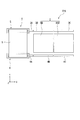
Classifications
-
- H—ELECTRICITY
- H10—SEMICONDUCTOR DEVICES; ELECTRIC SOLID-STATE DEVICES NOT OTHERWISE PROVIDED FOR
- H10P—GENERIC PROCESSES OR APPARATUS FOR THE MANUFACTURE OR TREATMENT OF DEVICES COVERED BY CLASS H10
- H10P72/00—Handling or holding of wafers, substrates or devices during manufacture or treatment thereof
- H10P72/04—Apparatus for manufacture or treatment
- H10P72/0448—Apparatus for applying a liquid, a resin, an ink or the like
-
- B—PERFORMING OPERATIONS; TRANSPORTING
- B05—SPRAYING OR ATOMISING IN GENERAL; APPLYING FLUENT MATERIALS TO SURFACES, IN GENERAL
- B05B—SPRAYING APPARATUS; ATOMISING APPARATUS; NOZZLES
- B05B13/00—Machines or plants for applying liquids or other fluent materials to surfaces of objects or other work by spraying, not covered by groups B05B1/00 - B05B11/00
- B05B13/02—Means for supporting work; Arrangement or mounting of spray heads; Adaptation or arrangement of means for feeding work
- B05B13/04—Means for supporting work; Arrangement or mounting of spray heads; Adaptation or arrangement of means for feeding work the spray heads being moved during spraying operation
-
- B—PERFORMING OPERATIONS; TRANSPORTING
- B05—SPRAYING OR ATOMISING IN GENERAL; APPLYING FLUENT MATERIALS TO SURFACES, IN GENERAL
- B05B—SPRAYING APPARATUS; ATOMISING APPARATUS; NOZZLES
- B05B14/00—Arrangements for collecting, re-using or eliminating excess spraying material
- B05B14/30—Arrangements for collecting, re-using or eliminating excess spraying material comprising enclosures close to, or in contact with, the object to be sprayed and surrounding or confining the discharged spray or jet but not the object to be sprayed
-
- B—PERFORMING OPERATIONS; TRANSPORTING
- B05—SPRAYING OR ATOMISING IN GENERAL; APPLYING FLUENT MATERIALS TO SURFACES, IN GENERAL
- B05C—APPARATUS FOR APPLYING FLUENT MATERIALS TO SURFACES, IN GENERAL
- B05C1/00—Apparatus in which liquid or other fluent material is applied to the surface of the work by contact with a member carrying the liquid or other fluent material, e.g. a porous member loaded with a liquid to be applied as a coating
- B05C1/04—Apparatus in which liquid or other fluent material is applied to the surface of the work by contact with a member carrying the liquid or other fluent material, e.g. a porous member loaded with a liquid to be applied as a coating for applying liquid or other fluent material to work of indefinite length
- B05C1/08—Apparatus in which liquid or other fluent material is applied to the surface of the work by contact with a member carrying the liquid or other fluent material, e.g. a porous member loaded with a liquid to be applied as a coating for applying liquid or other fluent material to work of indefinite length using a roller or other rotating member which contacts the work along a generating line
- B05C1/0826—Apparatus in which liquid or other fluent material is applied to the surface of the work by contact with a member carrying the liquid or other fluent material, e.g. a porous member loaded with a liquid to be applied as a coating for applying liquid or other fluent material to work of indefinite length using a roller or other rotating member which contacts the work along a generating line the work being a web or sheets
- B05C1/083—Apparatus in which liquid or other fluent material is applied to the surface of the work by contact with a member carrying the liquid or other fluent material, e.g. a porous member loaded with a liquid to be applied as a coating for applying liquid or other fluent material to work of indefinite length using a roller or other rotating member which contacts the work along a generating line the work being a web or sheets being passed between the coating roller and one or more backing rollers
-
- B—PERFORMING OPERATIONS; TRANSPORTING
- B65—CONVEYING; PACKING; STORING; HANDLING THIN OR FILAMENTARY MATERIAL
- B65H—HANDLING THIN OR FILAMENTARY MATERIAL, e.g. SHEETS, WEBS, CABLES
- B65H23/00—Registering, tensioning, smoothing or guiding webs
- B65H23/02—Registering, tensioning, smoothing or guiding webs transversely
- B65H23/032—Controlling transverse register of web
-
- H—ELECTRICITY
- H10—SEMICONDUCTOR DEVICES; ELECTRIC SOLID-STATE DEVICES NOT OTHERWISE PROVIDED FOR
- H10P—GENERIC PROCESSES OR APPARATUS FOR THE MANUFACTURE OR TREATMENT OF DEVICES COVERED BY CLASS H10
- H10P72/00—Handling or holding of wafers, substrates or devices during manufacture or treatment thereof
- H10P72/30—Handling or holding of wafers, substrates or devices during manufacture or treatment thereof for conveying, e.g. between different workstations
- H10P72/32—Handling or holding of wafers, substrates or devices during manufacture or treatment thereof for conveying, e.g. between different workstations between different workstations
- H10P72/3202—Mechanical details, e.g. rollers or belts
-
- H—ELECTRICITY
- H10—SEMICONDUCTOR DEVICES; ELECTRIC SOLID-STATE DEVICES NOT OTHERWISE PROVIDED FOR
- H10P—GENERIC PROCESSES OR APPARATUS FOR THE MANUFACTURE OR TREATMENT OF DEVICES COVERED BY CLASS H10
- H10P72/00—Handling or holding of wafers, substrates or devices during manufacture or treatment thereof
- H10P72/30—Handling or holding of wafers, substrates or devices during manufacture or treatment thereof for conveying, e.g. between different workstations
- H10P72/32—Handling or holding of wafers, substrates or devices during manufacture or treatment thereof for conveying, e.g. between different workstations between different workstations
- H10P72/3211—Changing orientation of the substrate, e.g. from a horizontal position to a vertical position
Definitions
- the present invention relates to a substrate processing apparatus.
- This application claims priority based on US Provisional Application No. 61 / 446,197 filed on Feb. 24, 2011, the contents of which are incorporated herein by reference.
- a display element constituting a display device such as a display device
- a liquid crystal display element and an organic electroluminescence (organic EL) element are known.
- organic EL organic electroluminescence
- active elements active devices that form thin film transistors (TFTs) on the substrate surface corresponding to each pixel have become mainstream.
- a technique for forming a display element on a sheet-like substrate for example, a film member
- a technique called a roll-to-roll system for example, a technique called a roll-to-roll system (hereinafter simply referred to as “roll system”) is known (see, for example, Patent Document 1).
- roll system a technique called a roll-to-roll system
- one sheet-like substrate for example, a belt-like film member
- the fed substrate is wound around the substrate collection side recovery roller
- the substrate is subjected to desired processing by a processing apparatus installed between the supply roller and the collection roller.
- the substrate is transported using a plurality of transport rollers, etc., and the gate electrode and gate insulating film constituting the TFT using a plurality of processing devices (units)
- a semiconductor film, source / drain electrodes, and the like are formed, and components of the display element are sequentially formed on the surface to be processed of the substrate.
- a light emitting layer, an anode, a cathode, an electric circuit, and the like are sequentially formed on a substrate.
- a supply roller that feeds a flexible substrate formed in a strip shape, a collection roller that winds up the substrate sent from the supply roller, a feed roller that is fed from the supply roller, and a recovery roller
- a chamber that encloses a part of the substrate that is being wound, a processing unit that is accommodated in the chamber and processes a part of the substrate that is surrounded by the chamber, and a substrate that is directed from the supply roller to the recovery roller
- Substrate processing provided with a drive unit that relatively moves the supply roller, the recovery roller, the chamber, and the processing unit so that a part of the substrate is carried into and out of the chamber in a direction that intersects the feeding direction.
- movement of the substrate processing apparatus which concerns on this embodiment The figure which shows the mode of operation
- movement of the substrate processing apparatus which concerns on this embodiment The figure which shows the mode of operation
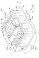
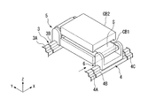
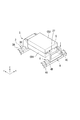
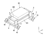
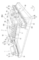
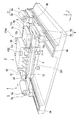
- FIG. 1 is a perspective view showing the overall configuration of the substrate processing apparatus FPA according to the present embodiment.
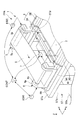
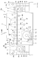
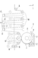
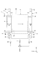
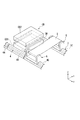
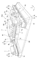
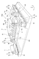
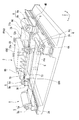
- 2 and 3 are perspective views showing a state of a part of the configuration of the substrate processing apparatus FPA when viewed from a different viewpoint from FIG.
- the substrate processing apparatus FPA includes a transport unit 1 that transports a flexible substrate S formed in a strip shape, a processing unit 2 that performs a predetermined process on the substrate S, And a control unit CONT for comprehensively controlling the transport unit 1 and the processing unit 2.
- the substrate processing apparatus FPA is provided, for example, on a base (pedestal) ST placed on the floor surface FL of the manufacturing factory.
- the substrate processing apparatus FPA is an apparatus of a roll-to-roll system (hereinafter simply referred to as “roll system”) that performs various processes on the surface of the flexible substrate S formed in a strip shape.
- the substrate processing apparatus FPA is used when a display element (electronic device) such as an organic EL element or a liquid crystal display element is formed on the substrate S.
- a display element electronic device
- the substrate processing apparatus FPA may be used in a system for forming elements other than these elements (for example, solar cells, color filters, touch panels, etc.).
- an XYZ orthogonal coordinate system is set, and the positional relationship of each member will be described with reference to the XYZ orthogonal coordinate system.
- a plane parallel to the floor surface FL in the XYZ orthogonal coordinate system is an XY plane.
- the direction in which the substrate S moves is the Y direction
- the direction orthogonal to the Y direction is the X direction.
- a direction perpendicular to the floor surface FL (XY plane) is taken as a Z-axis direction.
- the resin film is polyethylene resin, polypropylene resin, polyester resin, ethylene vinyl copolymer resin, polyvinyl chloride resin, cellulose resin, polyamide resin, polyimide resin, polycarbonate resin, polystyrene resin, vinyl acetate resin, polyethylene terephthalate, polyethylene Materials such as naphthalate and stainless steel foil can be used.
- the dimension in the short direction of the substrate S is, for example, about 50 cm to 2 m, and the dimension in the long direction (size for one roll) is, for example, 10 m or more.
- this dimension is only an example and is not limited thereto.
- the dimension in the short direction of the substrate S may be 1 m or less, 50 cm or less, or 2 m or more.
- substrate S may be 10 m or less.
- the substrate S has a thickness of 1 mm or less, for example, and is formed to have flexibility.
- the term “flexibility” refers to the property that the substrate can be bent without being broken or broken even when a predetermined force of at least its own weight is applied to the substrate. Further, for example, the property of bending by the predetermined force is also included in the flexibility.
- the flexibility varies depending on the material, size, thickness, or environment such as temperature and humidity of the substrate.
- a single strip-shaped substrate may be used, but a configuration in which a plurality of unit substrates are connected and formed in a strip shape may be used.
- the substrate S preferably has a relatively small coefficient of thermal expansion so that the dimensions do not substantially change even when subjected to heat at a relatively high temperature (for example, about 200 ° C.) (thermal deformation is small).
- a relatively high temperature for example, about 200 ° C.
- an inorganic filler can be mixed with a resin film to reduce the thermal expansion coefficient.
- the inorganic filler include titanium oxide, zinc oxide, alumina, silicon oxide and the like.
- the base ST has a base part STa, a leg part STb, and a support base STc.
- Base portion STa is placed on floor surface FL.
- a plurality of leg portions STb are provided on the base portion STa and support the support base STc.
- the support base STc is formed in, for example, a rectangle, and is provided with an opening to which the processing unit 2 is attached and two openings STd provided so as to sandwich the opening in the X direction. That is, the support STc is provided with three openings STd along the X direction.
- Guide rails 7r extending in parallel to the Y-axis direction are provided in the three openings STd. Two guide rails 7r are provided in parallel in the X direction for each opening STd.
- the conveyance unit 1 includes a first rail 3, a second rail 4, a substrate feeding mechanism 5, a substrate winding mechanism 6, a rail driving mechanism (rail driving unit) 7, and a roller driving unit 8.
- the first rail 3 is disposed along the + Y side of the support base STc.
- the first rail 3 is divided into three unit rails 3A to 3C.
- Each of the unit rails 3A to 3C is disposed at a position corresponding to each of the three openings STd of the support base STc.
- the dimension in the X direction of the unit rails 3A to 3C is a value corresponding to the dimension in the X direction of each opening STd.
- the second rail 4 is disposed along the ⁇ Y side of the support base STc.
- the second rail 4 is divided into three unit rails 4A to 4C.
- Each of the unit rails 4A to 4C is arranged at a position corresponding to each of the three openings STd of the support base STc, like the unit rails 3A to 3C.
- the X-direction dimensions of the unit rails 4A to 4C are values corresponding to the X-direction dimensions of the openings STd, and are the same as the X-direction dimensions of the unit rails 3A to 3C. .
- the unit rails 3A to 3C of the first rail 3 and the unit rails 4A to 4C of the second rail 4 are respectively supported by guide rails 7r provided in the respective openings STd and extending in the Y direction.
- the unit rails 3A to 3C are supported on the + Y side end of the guide rail 7r, and the unit rails 4A to 4C are supported on the ⁇ Y side end of the guide rail 7r.
- the unit rails 3A to 3C of the first rail 3 and the unit rails 4A to 4C of the second rail 4 are arranged in parallel with each other in the X direction. Further, since the guide rail 7r extends in parallel to the Y-axis direction, the unit rails 3A to 3C and the unit rails 4A to 4C can move in the Y direction on the guide rail 7r while maintaining a parallel state to each other. Is provided. As described above, the first rail 3 and the second rail 4 are configured to be linearly movable on a plane parallel to the XY plane by the guide rail 7r.
- the substrate delivery mechanism 5 is disposed on the first rail 3.
- the substrate delivery mechanism 5 has a roller support portion 5a and a supply roller 5b.
- the roller support portion 5 a is connected on the first rail 3 and is provided so as to be movable in the X direction along the first rail 3.
- the roller support portion 5a is movable over the unit rails 3A to 3C constituting the first rail 3.
- the supply roller 5b is rotatably supported by the roller support portion 5a.
- the supply roller 5b is supported so that the direction of the rotation axis coincides with a direction parallel to the X direction.
- the substrate S is wound around the supply roller 5b in a roll shape. By rotating the supply roller 5b, the substrate S wound around the supply roller 5b is sent out in the -Y direction.
- the supply roller 5b can be rotated by a motor or the like.
- the substrate winding mechanism 6 is disposed on the second rail 4.
- the substrate winding mechanism 6 includes a roller support portion 6a and a recovery roller 6b.
- the roller support portion 6 a is connected on the second rail 4 and is provided so as to be movable in the X direction along the second rail 4.
- the roller support portion 6a is movable over the unit rails 4A to 4C constituting the second rail 4 in the roller drive portion 8.
- the collection roller 6b is rotatably supported by the roller support portion 6a.
- the collection roller 6b is supported so that the direction of the rotation axis coincides with a direction parallel to the X direction.
- the substrate S is wound around the collection roller 6b in a roll shape. When the collection roller 6b rotates, the substrate S is wound around the collection roller 6b.
- the collection roller 6b can be rotated by a motor or the like.
- the rail drive mechanism 7 moves the first rail 3 and the second rail 4 in the Y direction along the guide rail 7r.
- the rail drive mechanism 7 can drive the first rail 3 for each of the unit rails 3A and 3C, and can drive the second rail 4 for each of the unit rails 4A and 4C.
- the control unit CONT can control the drive amount, drive speed, drive timing, and the like by the rail drive mechanism 7.
- the rail drive mechanism 7 can move the unit rail 3A and the unit rail 4A closer to each other or away from each other along the guide rail 7r.
- the rail drive mechanism 7 can move the unit rail 3C and the unit rail 4C closer to each other or away from each other along the guide rail 7r.
- the roller drive unit 8 has a first drive unit 83 and a second drive unit 84.
- the first drive unit 83 moves the roller support unit 5a in the X direction along the first rail 3, and rotates the supply roller 5b.
- the second drive unit 84 moves the roller support 6a along the second rail 4 in the X direction and rotates the collection roller 6b.
- the control unit CONT can control the first drive unit 83 and the second drive unit 84 individually or in synchronization. Further, the control unit CONT can control the drive amount, drive speed, drive timing, and the like in the first drive unit 83 and the second drive unit 84.
- the processing unit 2 has a processing surface (first surface) Sa of the substrate S on the movement path of the substrate S supplied from the substrate delivery mechanism 5 and conveyed to the substrate winding mechanism 6.
- the processing unit 2 includes a chamber device (chamber) CB, a chamber driving device 25, a processing device 10, a guide device 30, and an alignment measuring device 50.
- a printing machine is shown as the processing apparatus 10.
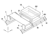
- the chamber device CB is disposed between the first rail 3 and the second rail 4 (between the unit rail 3B and the unit rail 4B in the present embodiment).
- the chamber apparatus CB is a housing that surrounds a portion of the substrate S that is disposed between the supply roller 5b and the collection roller 6b.
- the chamber apparatus CB has a first part CB1 provided on the surface Sa (surface to be processed) on the ⁇ Z side of the substrate S and a second part CB2 provided on the surface Sb on the + Z side of the substrate S. .
- the first portion CB1 and the second portion CB2 are connected so as to be relatively separable in the Z direction.
- the chamber apparatus CB has passage portions 26 and 27 through which the substrate S passes.
- the passage part 26 is an opening formed in the wall part on the + Y side of the chamber device CB.
- the passage part 26 includes a concave part 26a formed in the first part CB1 and a concave part 26b formed in the second part CB2.
- the passing portion 27 is an opening formed in the ⁇ Y side wall portion of the chamber apparatus CB.
- the passage part 27 includes a recess 27a formed in the first part CB1 and a recess 27b formed in the second part CB2. In a state where the first part CB1 and the second part CB2 are connected, the passage portions 26 and 27 are opened to the chamber device CB.
- the substrate S sent out from the supply roller 5b is carried into the chamber device CB via the passage portion 26 and is carried out from the chamber device CB via the passage portion 27.
- the chamber drive device 25 has support columns (support portions) 25a and 25b, bridging members 25c and 25d, and elevating mechanisms 25e and 25f.
- the support pillar 25a is fixed to the + Y side of the support ST (stage) STc of the base ST with respect to the first rail 3.
- the support column 25b is fixed to the ⁇ Y side of the second rail 4 in the support base (stage) STc of the base ST.
- the bridging member 25c is supported by the support pillar 25a.
- the bridging member 25c is fixed to the outer wall on the + Y side of the first portion CB1 of the chamber device CB.
- the bridging member 25d is supported by the support pillar 25b.
- the bridging member 25d is fixed to the outer wall on the ⁇ Y side of the first portion CB1 of the chamber device CB.
- the elevating mechanism 25e is provided on the support column 25a and is connected to the bridging member 25c.
- the elevating mechanism 25e has an actuator (not shown) that moves the bridging member 25c in the Z direction along the support column 25a.
- the elevating mechanism 25f is provided on the support column 25b and is connected to the bridging member 25d.
- the elevating mechanism 25f has an actuator (not shown) that moves the bridging member 25d in the Z direction along the support column 25b. Examples of the actuator include a motor mechanism and an air cylinder mechanism.
- first portion CB1 is supported from the outer side in the Y direction than the first rail 3 and the second rail 4.
- the first portion CB1 is configured to move integrally with the bridging members 25c and 25d in the Z direction along the support columns 25a and 25b by the lifting mechanisms 25e and 25f.
- the processing apparatus 10 is accommodated in, for example, the second part CB2 of the chamber apparatus CB.
- the processing apparatus 10 has various apparatuses for forming, for example, organic EL elements on the surface Sa to be processed of the substrate S.
- Examples of such an apparatus include a partition forming apparatus for forming a partition on the surface Sa, an electrode forming apparatus for forming an electrode, and a light emitting layer forming apparatus for forming a light emitting layer. More specifically, a droplet coating apparatus (for example, an ink jet type coating apparatus), a film forming apparatus (for example, a vapor deposition apparatus, a sputtering apparatus), an exposure apparatus, a developing apparatus, a surface modification apparatus, a cleaning apparatus, a drying apparatus, etc. It is done.
- a droplet coating apparatus for example, an ink jet type coating apparatus
- a film forming apparatus for example, a vapor deposition apparatus, a sputtering apparatus
- an exposure apparatus for example, a developing apparatus, a
- the processing apparatus 10 includes a transfer apparatus (for example, a gravure printing machine, a flexographic printing machine, etc.) 11 that transfers and forms a coating film on the surface Sa.
- a transfer apparatus for example, a gravure printing machine, a flexographic printing machine, etc.
- the transfer device 11 includes a transfer roller 11a, a coating liquid storage unit 11b, and a film thickness adjustment unit 11c. A part of the transfer roller 11a is attached to the coating liquid 11d stored in the coating liquid storage section 11b.
- the transfer roller 11a is rotatably provided in this state.
- the transfer device 11 has a rotation drive mechanism (not shown) (for example, a motor mechanism) that rotates the transfer roller 11a clockwise.
- the transfer device 11 is disposed, for example, on the + Y side of the center in the Y direction in the space in the chamber device CB.
- a lid 11e is provided on the + X side wall of the transfer roller 11a in the first portion CB1 of the chamber device CB.
- the lid portion 11e is formed to have a size larger than that of the transfer roller 11a when viewed in the X direction. For this reason, in a state where the lid portion 11e is opened, the transfer roller 11a can be taken in and out of the first portion CB1 in the X direction.
- the guide device 30 has a plurality of guide rollers GR and a plurality of guide pads GP for guiding the substrate S in the processing unit 2.
- the plurality of guide rollers GR are provided along the transport path of the substrate S.
- Three guide rollers GR1 among the plurality of guide rollers GR function as pressing rollers that press the surface Sa to be processed of the substrate S against the transfer roller 11a.
- the three guide rollers GR1 are movable so that the positional relationship is not changed by a guide member (not shown).
- three guide rollers GR2 among the plurality of guide rollers GR guide the back surface Sb of the substrate S after the coating liquid is transferred.
- a plurality (three in this case) of guide pads GP guide the surface Sa to be processed of the substrate S after the coating liquid is transferred.
- Each of the plurality of guide pads GP includes a plurality of unillustrated jet outlets for ejecting gas from the cylindrical guide surface GPa, and can form a gas layer on the guide surface GPa. . By this gas layer, the guide surface GPa can be guided in a non-contact manner with respect to the processing surface Sa of the substrate S.
- the guide roller GR2 and the guide pad GP are alternately arranged in the Y direction.
- the guide rollers GR3 and GR4 are provided at fixed positions in the second portion CB2.
- the guide roller GR5 is disposed on the + Y side of the second portion CB2, and is provided so as to be movable in the Z direction.
- the guide roller GR5 is configured to sandwich the substrate S with the guide roller GR3 by moving to the ⁇ Z side.
- the alignment measuring device 50 measures an edge portion of the substrate S or an alignment mark provided on the substrate S, and performs an alignment operation on the substrate S based on the measurement result.
- the alignment measurement apparatus 50 includes an alignment camera that detects an edge portion of the substrate S or an alignment mark, an adjustment device that adjusts at least one of the position and orientation of the substrate S based on the detection result of the alignment camera, and the like. Yes.
- a method of projecting a laser beam on the substrate S by a method like an optical mouse and photoelectrically detecting a change in a speckle pattern generated on the substrate S can be used.
- 4 to 14 are diagrams showing the operation of the substrate processing apparatus FPA. First, the case where the operation
- the control unit CONT arranges the substrate feed mechanism 5 on the unit rail 3 ⁇ / b> A of the first rail 3 and arranges the substrate take-up mechanism 6 on the unit rail 4 ⁇ / b> A of the second rail 4.
- the supply roller 5b and the collection roller 6b are arranged in parallel so as to face each other in the Y direction.
- the substrate S wound in a roll shape is attached to the supply roller 5b.
- the reader Lf is attached to the tip Sf of the substrate S.
- the reader Lf may be omitted.
- the control unit CONT moves the unit rail 4A of the second rail 4 in the + Y direction. By this operation, the supply roller 5b and the collection roller 6b come closer.
- the control unit CONT rotates the supply roller 5b by the first driving unit 83 when the distance between the supply roller 5b and the collection roller 6b becomes the first distance D1.
- the tip Sf of the substrate S is sent out to the collection roller 6b side, and the tip Sf of the substrate S reaches the collection roller 6b and is wound around the collection roller 6b.
- the operation of winding the tip Sf of the substrate S around the collection roller 6b may be automated, but the tip Sf may be manually attached to the collection roller 6b by using a fixing tape or the like.
- the controller CONT rotates the supply roller 5b after the tip Sf of the substrate S is hung on the collection roller 6b, and moves the unit rail 4A in the ⁇ Y direction until the substrate take-up mechanism 6 reaches the original position. Move. By this operation, the front end Sf of the substrate S is pulled out in the ⁇ Y direction in a state where it is hung on the collection roller 6b.
- the control unit CONT stops the movement of the substrate winding mechanism 6. Thereafter, as shown in FIG. 5, the control unit CONT moves the second part CB2 of the chamber apparatus CB in the + Z direction to form a gap through which the substrate S can pass between the first part CB1 and the second part CB2. To do. At this time, an appropriate tension is applied to the substrate S spanned between the supply roller 5b and the collection roller 6b in the Y direction, and the substrate S forms a gap between the first portion CB1 and the second portion CB2. To be able to pass. The tension of the substrate S can be adjusted by controlling the substrate winding mechanism 6.
- the control unit CONT synchronizes the substrate feed mechanism 5 and the substrate take-up mechanism 6 with the first drive units 83 and 84, and onto the unit rail 3 ⁇ / b> B and the unit rail 4 ⁇ / b> B, respectively.
- the substrate S is disposed at a position sandwiched between the concave portions 26a and 27a of the first portion CB1 and the concave portions 26b and 27b of the second portion CB2 in the Z direction.
- the controller CONT disposes the substrate delivery mechanism 5 and the substrate take-up mechanism 6 on the unit rails 3B and 4B, respectively, and then moves the second part CB2 in the ⁇ Z direction as shown in FIG. CB1 and the second part CB2 are connected. In this state, the first part CB1 and the second part CB2 come into contact with each other, and the gap between the first part CB1 and the second part CB2 is closed.
- the substrate S enters the inside of the chamber device CB at the passage portion 26 and comes out of the chamber device CB at the passage portion 27.
- the control part CONT puts the guide device 30 in the chamber device CB on standby.
- the guide rollers GR1 and GR2 are arranged on the + Z side of the substrate S, and the guide pad GP is arranged on the ⁇ Z side of the substrate S.
- each of the substrate delivery mechanism 5 and the substrate take-up mechanism 6 is provided with elevators 5d and 6d for adjusting the heights of the supply roller 5b and the recovery roller 6b. The height is adjusted so that the substrate S across the take-up mechanism 6 is substantially horizontal.
- the guide roller GR1 is moved in the ⁇ Z direction to press the substrate S toward the ⁇ Z side, and the surface Sa to be processed is brought into contact with the transfer roller 11a. Further, the guide roller GR2 is moved in the ⁇ Z direction, and the guide pad GP is moved to the + Z side.
- the substrate S is guided by being bent back many times in the chamber apparatus CB in the Z direction. For this reason, it is conveyed in the state which the board
- the control unit CONT rotates the supply roller 5b and the collection roller 6b in accordance with the processing timing of the transfer device 11, and rotates the transfer roller 11a.
- the substrate S is sent out from the supply roller 5b and the substrate S is wound up by the recovery roller 6b.
- the transfer process of the coating film by the transfer device 11 is performed on the surface Sa to be processed of the substrate S. Will be done.
- the guide surface GPa of the guide pad GP that supports the target surface Sa of the substrate S, so that the substrate S can be transported in a non-contact state with respect to the coating film.
- a portion of the substrate S guided by the guide roller GR2 and the guide pad GP may be dried using, for example, a drying device such as a heating device.
- the control unit CONT adjusts the moving speed of the substrate S moving from the supply roller 5b to the collection roller 6b according to the processing speed of the transfer device 11.
- the first drive unit 83 and the second drive The drive speed in the unit 84 is adjusted.
- the substrate S is transported while the transport speed is constant.
- the speed of the substrate S is also monitored based on the timing (time) at which the alignment measuring device 50 in FIG. 3 measures the alignment mark provided on the substrate S.
- the elevators 5d and 6d may be adjusted by changing the winding diameter R1 of the substrate S and the winding diameter R2 of the substrate S.
- the control unit CONT may adjust the distance between the supply roller 5b and the collection roller 6b in accordance with the processing position and dimensions of the transfer device 11.
- the control unit CONT causes the rail drive mechanism 7 to move, for example, the unit rail 3B or the unit rail 4B in the Y direction, respectively.
- a part of the constituent elements of the display element is sequentially formed on the substrate S by the transfer device 11.
- FIG. 11 shows a state of the chamber apparatus CB in a state where the processing for the substrate S is completed. From this state, as shown in FIG. 12, the control unit CONT moves the second part CB2 of the chamber apparatus CB to the + Z side, and a gap through which the substrate S can pass between the first part CB1 and the second part CB2. Form.
- the control unit CONT synchronizes the substrate feed mechanism 5 and the substrate take-up mechanism 6 by the synchronous control of the first drive units 83 and 84, and the unit rail 3C and the unit rail are respectively synchronized.
- Move up 4C By this operation, the substrate S is retracted from the position sandwiched between the first portion CB1 and the second portion CB2 to the + X side.
- the substrate feed mechanism 5 and the substrate take-up mechanism 6 are arranged on the unit rail 3C and the unit rail 4C, the movement of the substrate feed mechanism 5 and the substrate take-up mechanism 6 is stopped.
- the control unit CONT stops the movement of the substrate feed mechanism 5 and the substrate take-up mechanism 6, and then moves the unit rail 4C in the + Y direction while rotating the collection roller 6b. By this operation, the supply roller 5b and the recovery roller 6b come close again while the recovery roller 6b winds up the substrate S.
- the control unit CONT rotates the supply roller 5b by the second drive unit 84 as shown in FIG. 14 after the distance between the supply roller 5b and the collection roller 6b becomes the second distance D2.
- the 2nd distance D2 it can be set as the distance equal to said 1st distance D1, for example.
- the rear end Se of the substrate S is sent out to the collection roller 6b side, and the rear end Se of the substrate S reaches the collection roller 6b and is wound around the collection roller 6b.
- the reader Le is attached to the rear end Se of the substrate S.
- the reader Le may be omitted.
- the control unit CONT moves the unit rail 4C in the ⁇ Y direction until the substrate winding mechanism 6 moves to the original position after the rear end Se of the substrate S is hung on the collection roller 6b. After the substrate winding mechanism 6 returns to the original position, the roll-shaped substrate S wound around the collection roller 6b is moved to the next processing apparatus. Or when all the processes are performed with respect to the board
- the substrate S is carried into and out of the chamber apparatus CB in a direction intersecting the moving direction of the substrate S from the supply roller 5b toward the collection roller 6b. Since the supply roller 5b, the recovery roller 6b, the chamber device CB, and the transfer device 11 are relatively moved, the substrate S is kept in a constant size while being fed and wound up.
- the substrate can be carried into the processing apparatus 10 and the substrate S can be processed. Thereby, since it can suppress that the dimension of the board
- FIG. 15 is a cross-sectional view showing the configuration of the substrate processing apparatus FPA2 according to this embodiment.
- a pressure adjusting device (pressure adjusting unit) 60 such as a pump is connected to the chamber device CB, and the pressure inside the chamber device CB is adjusted (for example, pressurization, decompression). It has a possible configuration.
- the chamber apparatus CB as the processing apparatus 10, for example, a plasma apparatus 12 that performs processing in a reduced pressure environment is provided.
- Differential exhaust chambers 61 and 62 are provided on the + Y side of the chamber apparatus CB, and differential exhaust chambers 63 and 64 are provided on the ⁇ Y side of the chamber apparatus CB.
- a pump is also connected to each differential exhaust chamber 61-64.
- the differential exhaust chambers 61 to 64 have first portions 61a to 64a disposed on the ⁇ Z side of the substrate S and second portions 61b to 64b disposed on the + Z side of the substrate S, respectively.
- the first portions 61a to 64a of the differential exhaust chambers 61 to 64 are provided integrally with the first portion CB1 of the chamber device CB (third portion CB3).
- the second portions 61b to 64b of the differential exhaust chambers 61 to 64 are provided integrally with the second portion CB2 of the chamber device CB (fourth portion CB4).
- the third part CB3 and the fourth part CB4 are provided so as to be separable in the Z direction.
- a seal mechanism 65 is provided between the third part CB3 and the fourth part CB4.
- the seal mechanism 65 can seal the inside of each differential exhaust chamber 61 to 64, the inside of the chamber device CB, and the substrate S in a state where the third portion CB3 and the fourth portion CB4 are connected. It has a configuration (air tight state).
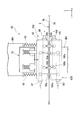
- FIG. 16 is a diagram illustrating a configuration of the seal mechanism 65.
- the seal mechanism 65 includes a first air pad mechanism 65A and a second air pad mechanism 65B that sandwich the substrate S in the Z direction, and a pressing mechanism 70 that presses the first air pad mechanism 65A toward the second air pad mechanism 65B. And have.
- the first air pad mechanism 65A is connected to a pad 66 having an air jet port 66a and an air suction port 66b provided on the surface facing the -Z side, and an air supply unit (not shown) that supplies air such as nitrogen gas. And a suction side connection portion 68 connected to a suction pump (not shown).
- the air ejection port 66 a is connected to the supply side connection portion 67 through a flow path in the pad 66.
- the air suction port 66 b is connected to the suction side connection portion 68 through a flow path in the pad 66.
- the second air pad mechanism 65B is connected to a pad 166 provided with an air ejection port 166a and an air suction port 166b on the surface directed toward the + Z side, and an air supply unit (not shown) that supplies air such as nitrogen gas.
- the air ejection port 166 a is connected to the supply side connection portion 167 via a flow path in the pad 166.
- the air suction port 166 b is connected to the suction side connection portion 168 via a flow path in the pad 166.
- the pressure inside the chamber apparatus CB can be stabilized. Further, since the space between the third portion CB3, the fourth portion CB4 and the substrate S can be closed with a high degree of sealing, it is possible to prevent foreign matter from entering the chamber device CB and the differential exhaust chambers 61 to 64. it can.
- FIG. 17 is a cross-sectional view showing the configuration of the substrate processing apparatus FPA3 according to this embodiment.
- each of the first portion CB1 and the second portion CB2 of the chamber device CB is provided with a storage chamber opening / closing mechanism SL.
- the storage chamber opening / closing mechanism SL has a slide mechanism (opening / closing part) SL1 attached to the first part CB1 and a sliding mechanism (opening / closing part) SL2 attached to the second part CB2.
- the slide mechanism SL1 has a pair of slide members 71a and 71b.
- the slide members 71a and 71b are provided so as to be movable in the X direction.
- the slide members 71a and 71b are provided so that the accommodation chamber RM1 of the first part CB1 can be opened and closed. In a state where the slide members 71a and 71b are opened, the accommodation chamber RM1 is opened to the atmosphere. In a state where the slide members 71a and 71b are closed, the storage chamber RM1 is sealed.
- the slide member 71a is accommodated in a slide accommodating portion (accommodating portion) 73a provided in the flange portion 73 of the first portion CB1, and the slide member 71b is accommodated in the flange portion 74 of the first portion CB1. It is accommodated in the provided slide accommodating portion (accommodating portion) 74a.
- the first portion CB1 has a configuration in which the flange portions 73 and 74 used for connection with the second portion CB2 also serve as the accommodating portions of the slide members 71a and 71b.
- the slide mechanism SL2 has a pair of slide members 72a and 72b.
- the slide members 71a and 71b are provided so as to be movable in the X direction.
- the slide members 72a and 72b are provided so that the accommodation chamber RM2 of the second part CB2 can be opened and closed.
- the slide members 72a and 72b function to maintain the decompressed state of the accommodation chamber RM2.
- the storage chamber RM2 is sealed.
- the slide member 72a is accommodated in a slide accommodating portion (accommodating portion) 75a provided in the flange portion 75 of the second portion CB2, and the slide member 72b is accommodated in the flange portion of the second portion CB2. It is accommodated in a slide accommodating portion (accommodating portion) 76 a provided in 76.
- the second portion CB2 has a configuration in which the flange portions 75 and 76 used for connection to the first portion CB1 also serve as the accommodating portions of the slide members 72a and 72b.
- connection mechanism 77 is provided in the first part CB1.
- the connection mechanism 77 has a vacuum packing 77a and an air seal mechanism 77b.
- a connection mechanism 78 is provided in the second portion CB2.
- the connection mechanism 78 has a vacuum packing 78a and an air seal mechanism 78b.
- the first part CB1 and the second part CB2 are connected in a sealed state by the connection mechanisms 77 and 78.
- an elevating mechanism 79 is connected to the first part CB1, and an elevating mechanism 80 is connected to the second part CB2.
- the first part CB1 and the second part CB2 can be moved up and down individually in the Z direction.
- differential exhaust chambers 85 and 86 are integrally attached to the + Y side and the ⁇ Y side of the chamber device CB, respectively.
- the substrate processing apparatus FPA3 includes, as the processing apparatus 10, a first processing apparatus 13 accommodated in the first part CB1 and a second processing apparatus 14 accommodated in the second part CB2. Note that a configuration in which one of the first processing device 13 and the second processing device 14 is omitted may be employed. Pressure adjusting devices 81 and 82 such as vacuum pumps are connected to the first part CB1 and the second part CB2, respectively. As the 1st processing apparatus 13 and the 2nd processing apparatus 14, the plasma apparatus etc. which process in a pressure-reduced environment are provided, for example.
- the operation of the substrate processing apparatus FPA3 configured as described above will be described.
- the operation when replacing the substrate S from the state where the processing for the substrate S is completed will be described as an example.
- FIG. 18 shows a state of the chamber apparatus CB in a state where the processing for the substrate S is completed.
- the inside of the chamber apparatus CB is in a reduced pressure state.
- the control unit CONT first closes the slide members 72a and 72b provided in the second portion CB2.
- the accommodation room RM2 (see FIG. 17) of the second part CB2 is sealed, and the decompression state of the accommodation room RM2 is maintained.
- the control unit CONT closes the slide members 71a and 71b provided in the first portion CB1, as shown in FIG. And By this operation, the accommodation chamber RM1 (see FIG. 17) of the first portion CB1 is also sealed, and the decompression state of the accommodation chamber RM1 is maintained. At this time, since the space between the slide members 71a and 71b and the slide members 72a and 72b is in a reduced pressure state, the pneumatic system is operated to return only this space to atmospheric pressure.
- the control unit CONT returns the pressure in the differential exhaust chambers 85 and 86 to atmospheric pressure, and then moves the first part CB1 to the ⁇ Z side as shown in FIG.
- the two parts CB2 are separated.
- the space between the slide members 71a and 71b and the slide members 72a and 72b is released to the atmosphere, and the accommodation chamber RM1 of the first part CB1 and the accommodation room RM2 of the second part CB2 are not released to the atmosphere.
- the controller CONT moves the substrate feeding mechanism 5 and the substrate take-up mechanism 6 waiting on the ⁇ X side of the chamber apparatus CB in the + X direction. To move the new substrate S between the first part CB1 and the second part CB2. Thereafter, the control unit CONT moves the first part CB1 to the + Z side to connect the first part CB1 and the second part CB2.
- the control unit CONT is a pneumatic system for exhausting the air remaining in the narrow space sandwiched between the slide members 71a and 71b and the slide members 72a and 72b.
- the narrow space becomes almost the same decompressed state as in the storage chamber RM1 of the first part CB1 or the storage chamber RM2 of the second part CB2
- the slide members 71a and 71b are opened and the slide The members 72a and 72b are opened. 18 to 22, the substrate S is pulled out from the lower side of the roll, and the surface opposite to the processing surface of the substrate S in FIG. 17 is processed.
- the separation and connection between the first part CB1 and the second part CB2 are performed by the movement of only the first part CB1, but the movement of only the second part CB2 or the first part CB1 and the second part CB2. It may be done by movement.
- the substrate processing apparatus FPA3 having a high throughput is obtained.
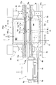
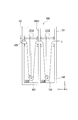
- FIG. 23A is a diagram showing a configuration of a differential exhaust device (differential exhaust chamber) 100 according to the present embodiment.
- the differential exhaust device 100 is disposed alone, but this differential exhaust device 100 can also be incorporated as the differential exhaust chambers 85 and 86 shown in FIGS. Is.
- the differential exhaust device 100 is configured to be separable into a first portion 101 and a second portion 102.
- the differential exhaust device 100 is formed to be long in the Z direction.
- the first portion 101 is provided with a partition portion 101C that partitions the inside of the first portion 101 into two storage chambers 101A and 101B.
- the first portion 101 is provided with opening and closing members 105 and 106 for individually opening and closing the storage chamber 101A and the storage chamber 101B. In a state where the opening and closing members 105 and 106 are closed, the storage chambers 101A and 101B are in a sealed state.
- the second portion 102 is provided with a partition portion 102C that partitions the inside of the second portion 102 into two storage chambers 102A and 102B.
- the second portion 102 is provided with opening / closing members 107 and 108 for individually opening and closing the storage chamber 102A and the storage chamber 102B. When the opening and closing members 107 and 108 are closed, the storage chambers 102A and 102B are in a sealed state.
- the second portion 102 is formed so that the dimension in the Z direction is larger than that of the first portion 101.
- the volumes of the storage chambers 102A and 102B are larger than the volumes of the storage chambers 101A and 101B.
- an air blowing port for drying the substrate S may be arranged in the storage chambers 102A and 102B.
- a configuration in which a pressure adjustment mechanism that adjusts the pressure in the storage chambers 102A and 102B, an atmosphere adjustment mechanism that adjusts the atmosphere in the storage chambers 102A and 102B, and the like may be provided.
- rollers (or guide pads GP as shown in FIG. 3) 103 and 104 for guiding the substrate S are provided, respectively.
- the rollers 103 and 104 are provided so as to be movable in the Z direction so as to straddle between the accommodation chambers 102A and 102B of the second portion 102.
- a seal mechanism 109 is provided between the first portion 101 and the second portion 102.
- the sealing mechanism 109 includes a first pad 109a provided on the ⁇ Z side end face of the first portion 101 and a second pad provided on the + Z side end face of the second portion 102, similarly to the configuration shown in FIG. 109b.
- the first pad 109a and the second pad 109b are provided at positions where the substrate S is sandwiched.
- the first pad 109a and the second pad 109b have a gas layer forming portion (not shown) that forms a gas layer on the surface, as in FIG.
- the first portion 101 and the second portion 102 are connected so as to sandwich the substrate S, and the slide member 71a shown in FIG. , 71b, 72a, 72b, the open / close members 105 to 108 that function in the same manner are opened. Thereafter, the rollers 103 and 104 are moved to the ⁇ Z side. By this operation, the substrate S is sandwiched between the gas layer of the first pad 109a and the gas layer of the second pad 109b and is held in a non-contact state.
- the installation area of the differential exhaust device 100 can be reduced by forming the differential exhaust device 100 longitudinally in the Z direction.
- the differential exhaust device 100 can be separated into the first portion 101 and the second portion 102 while maintaining the pressure and atmosphere of the storage chambers 102A and 102B having a large volume.
- the resetting of the pressure and atmosphere in the exhaust device 100 can be omitted or the time required for resetting can be reduced. For this reason, efficient processing can be performed on the substrate S.
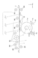
- the guide rollers GR1, GR2, GR5 and the guide pad GP are moved to a position inclined in the ⁇ X direction.
- these guide rollers GR1, GR2, GR5 and the guide pad GP move, as shown in FIG. 25, it is possible to save space in the Z direction as compared with the configuration in the first embodiment.
- the positional relationship of the three guide rollers GR1 that press the substrate S against the transfer roller 11a is the same as the positional relationship of the guide rollers GR1 in the first embodiment. For this reason, the conditions when the coating film is transferred to the substrate S by the transfer roller 11a are the same as the conditions in the first embodiment.
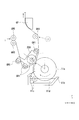
- the bearings of the three guide rollers GR1 may be fixed by a fixing member 200.
- the substrate S can be brought into contact with an arbitrary position of the transfer roller 11a by adjusting the angular position of the fixing member 200 around the rotation axis of the transfer roller 11a.
- substrate S can be made to contact the position closer to the film thickness adjustment part 11c, for example according to the kind of coating liquid. Thereby, it can transfer to the board
- the optical sensor 300 for detecting the substrate S may be arranged in at least one of the passage part 26 and the passage part 27 of the chamber apparatus CB.
- a configuration in which a drying unit 305 having an injection unit 303 for injecting dry gas in the X direction in the chamber device CB may be provided.
- the drying unit 305 may be provided with an airflow adjustment plate (airflow adjustment unit) 301 that regulates the flow of the dry gas from the ejection unit 303 to the transfer roller 11a side.
- a bellows portion 302 that expands and contracts according to the movement of the guide roller GR2 may be provided between the guide roller GR2 and the wall portion (ceiling portion) on the + Z side of the second portion CB2.
- the bellows portion 302 may also be provided between the guide pad GP and the wall portion (bottom portion) on the ⁇ Z side of the first portion CB1.
- the sub chamber apparatus (preliminary processing unit) SCB may be arranged on the side of the movement direction (Y direction) of the substrate S with respect to the chamber apparatus CB.
- the sub-chamber device SCB has the same configuration as the chamber device CB.
- the sub chamber apparatus SCB accommodates the same constituent elements as the constituent elements (including the processing apparatus 10) accommodated in the chamber apparatus CB. For this reason, even when the chamber apparatus CB is stopped, the same process as the process in the chamber apparatus CB can be performed in the sub-chamber apparatus SCB.
- the substrate S which is usually processed by the chamber apparatus CB and passes through the sub-chamber apparatus SCB and exits in the + X direction. However, when the chamber apparatus CB is stopped and ink filling is performed, the substrate S is processed. Are switched so that they pass through the chamber device CB and are processed by the sub-chamber device SCB.
Landscapes
- Container, Conveyance, Adherence, Positioning, Of Wafer (AREA)
- Advancing Webs (AREA)
- Electroluminescent Light Sources (AREA)
- Liquid Crystal (AREA)
- Coating Apparatus (AREA)
- Exposure Of Semiconductors, Excluding Electron Or Ion Beam Exposure (AREA)
- Exposure And Positioning Against Photoresist Photosensitive Materials (AREA)
- Registering, Tensioning, Guiding Webs, And Rollers Therefor (AREA)
- Controlling Rewinding, Feeding, Winding, Or Abnormalities Of Webs (AREA)
- Replacement Of Web Rolls (AREA)
- Manufacturing Of Printed Wiring (AREA)
- Physical Vapour Deposition (AREA)
- Drying Of Solid Materials (AREA)
Abstract
Description
本願は、2011年2月24日に出願された米国特許仮出願61/446,197号に基づき優先権を主張し、その内容をここに援用する。
以下、図面を参照して、本発明の第一実施形態を説明する。
図1は、本実施形態に係る基板処理装置FPAの全体構成を示す斜視図である。図2及び図3は、基板処理装置FPAの一部の構成について、図1とは異なる視点から見たときの状態を示す斜視図である。
図1から図3に示すように、基板処理装置FPAは、帯状に形成され可撓性を有する基板Sを搬送する搬送部1と、基板Sに対して所定の処理を行う処理部2と、搬送部1及び処理部2を統括的に制御する制御部CONTとを有している。基板処理装置FPAは、例えば製造工場の床面FLに載置された基台(ペデスタル)ST上に設けられている。
まず、搬送部1のうち供給ローラー5bと回収ローラー6bとの間に基板Sを掛け渡す動作を行う場合について説明する。
次に、本発明の第二実施形態を説明する。
図15は、本実施形態に係る基板処理装置FPA2の構成を示す断面図である。
図15に示すように、本実施形態では、チャンバー装置CBにポンプなどの圧力調整装置(圧力調整部)60が接続されており、チャンバー装置CBの内部の圧力を調整(例えば加圧、減圧)可能な構成となっている。チャンバー装置CBには、処理装置10として、例えば減圧環境下で処理を行うプラズマ装置12が設けられている。チャンバー装置CBの+Y側には差動排気室61及び62が設けられており、チャンバー装置CBの-Y側には差動排気室63及び64が設けられている。各差動排気室61~64にもポンプが接続される。
図16に示すように、シール機構65は、基板SをZ方向に挟む第一エアパッド機構65A及び第二エアパッド機構65Bと、第一エアパッド機構65Aを第二エアパッド機構65B側へ押圧する押圧機構70とを有している。
次に、本発明の第三実施形態を説明する。
図17は、本実施形態に係る基板処理装置FPA3の構成を示す断面図である。
図17に示すように、チャンバー装置CBの第一部分CB1及び第二部分CB2のそれぞれには、収容室開閉機構SLが設けられている。収容室開閉機構SLは、第一部分CB1に取り付けられたスライド機構(開閉部)SL1と、第二部分CB2に取り付けられたスライド機構(開閉部)SL2とを有している。
なお、図18~図22の基板送り出し機構5において、基板Sは、ロールの下側から引き出され、図17における基板Sの処理面とは逆の面が処理される。
本実施形態では、第一部分CB1と第二部分CB2との分離や接続を、第一部分CB1のみの移動によって行っているが、第二部分CB2のみの移動によってまたは第一部分CB1及び第二部分CB2の移動によって行ってもよい。
次に、本発明の第四実施形態を説明する。
図23Aは、本実施形態に係る差動排気装置(差動排気室)100の構成を示す図である。
図23Aに示すように、本実施形態では、差動排気装置100が単独で配置されているが、この差動排気装置100は図18~22に示した差動排気室85及び86としても組み込めるものである。この差動排気装置100は第一部分101と第二部分102とに分離可能な構成となっている。差動排気装置100は、Z方向に長手となるように形成されている。
例えば、図8、図9に示した第一実施形態において、案内ローラーGR1、GR2、GR5及び案内パッドGPがZ方向に沿って移動する構成を例に挙げて説明したが、これに限られることは無く、図24のような変形が可能である。
Claims (27)
- 帯状に形成され可撓性を有する基板を送り出す供給ローラーと、
前記供給ローラーから送り出された前記基板を巻き取る回収ローラーと、
前記供給ローラーから送り出され、かつ前記回収ローラーで巻き取られる間にある前記基板の一部を囲うチャンバーと、
前記チャンバーに収容され、前記チャンバーで囲われた前記基板の一部に対して処理を行う処理部と、
前記供給ローラーから前記回収ローラーへ向けた前記基板の送り方向に対して交差する方向に前記基板の一部が前記チャンバーの内部に搬入及び搬出されるように、前記供給ローラー及び前記回収ローラーと前記チャンバー及び前記処理部とを相対的に移動させる駆動部と
を備える基板処理装置。 - 前記チャンバーは、前記基板の第1面側に配置される第一部分と、前記基板の第2面側に配置される第二部分とに分離可能に設けられている
請求項1に記載の基板処理装置。 - 前記供給ローラーと前記回収ローラーとを支持するステージを更に備え、
前記第一部分は、前記ステージに支持されている
請求項2に記載の基板処理装置。 - 前記ステージは、前記第一部分を支持する支持部を有し、
前記支持部は、前記基板の移動方向において、前記供給ローラーと前記回収ローラーとを挟む位置に一対設けられている
請求項3に記載の基板処理装置。 - 前記第一部分と前記第二部分とが互いに分離する方向に前記第一部分と前記第二部分とを相対的に移動させる第二駆動部を更に備え、
前記第二駆動部は、前記基板の搬入又は搬出に同期させて前記第一部分と前記第二部分との相対的な移動を行わせる
請求項2から請求項4のうちいずれか一項に記載の基板処理装置。 - 前記第一部分及び前記第二部分のうち少なくとも一方は、内部空間を開放及び閉塞させる開閉部を有する
請求項2から請求項5のうちいずれか一項に記載の基板処理装置。 - 前記第一部分の前記内部空間の圧力と、前記第二部分の前記内部空間の圧力とを個別に調整可能な圧力調整部
を更に備える請求項6に記載の基板処理装置。 - 前記第一部分及び前記第二部分は、互いに装着可能なフランジ部をそれぞれ有し、
前記開閉部は、移動可能なスライド部材を有し、
前記フランジ部は、前記スライド部材を収容する収容部を有する
請求項6又は請求項7に記載の基板処理装置。 - 前記チャンバーは、前記基板の移動方向の両端の壁部に前記基板を通過させる通過部を有する
請求項1から請求項8のうちいずれか一項に記載の基板処理装置。 - 前記通過部に設けられ、前記基板を検出する光センサ
を更に備える請求項9に記載の基板処理装置。 - 前記処理部は、前記基板に対して塗布液を転写する転写ローラーを有する
請求項1から請求項10のうちいずれか一項に記載の基板処理装置。 - 前記処理部は、前記基板を前記転写ローラーへ押圧する3つの押圧ローラーを有する
請求項11に記載の基板処理装置。 - 3つの前記押圧ローラーは、互いに位置が固定されている
請求項12に記載の基板処理装置。 - 3つの前記押圧ローラーは、前記転写ローラーのうち異なる位置に前記基板を押圧するように移動可能に設けられている
請求項12又は請求項13に記載の基板処理装置。 - 前記基板に転写された前記塗布液を乾燥させる乾燥部
を更に備える請求項11から請求項14のうちいずれか一項に記載の基板処理装置。 - 前記乾燥部は、前記基板の移動方向に交差する方向から前記基板に対して乾燥気体を噴射する噴射部を有する
請求項15に記載の基板処理装置。 - 前記乾燥部は、前記噴射部と前記転写ローラーとの間で前記乾燥気体の気流を調整する気流調整部を有する
請求項16に記載の基板処理装置。 - 前記基板の第1面側及び第2面側にそれぞれ配置され、前記基板が掛けられる複数の案内ローラーを更に備え、
前記気流調整部は、複数の前記案内ローラーに亘って設けられた蛇腹部を有する
請求項17に記載の基板処理装置。 - 前記基板の第1面側及び第2面側にそれぞれ配置され、前記基板が掛けられる複数の案内ローラー
を更に備える請求項1から請求項18のうちいずれか一項に記載の基板処理装置。 - 複数の前記案内ローラーは、前記基板の移動方向について、前記基板の前記第1面側と前記基板の前記第2面側とに交互に配置されている
請求項19に記載の基板処理装置。 - 前記チャンバーのうち前記基板の移動方向の側方に配置される壁部には、前記処理部を出し入れする蓋部が設けられている
請求項1から請求項20のうちいずれか一項に記載の基板処理装置。 - 前記チャンバーに対して前記基板の移動方向の側方に配置され、前記基板に前記処理部と同一の処理を行う予備処理部を更に備える
請求項1から請求項21のうちいずれか一項に記載の基板処理装置。 - 前記駆動部は、前記供給ローラー及び前記回収ローラーを、前記処理部と前記予備処理部との間で移動可能である
請求項22に記載の基板処理装置。 - 前記基板の移動方向に交差する方向に前記供給ローラーが移動可能となるように前記供給ローラーを支持する第一レールと、
前記基板の移動方向に交差する方向に前記回収ローラーが移動可能となるように前記回収ローラーを支持する第二レールと
前記第一レール及び前記第二レールのうち少なくとも一方を駆動するレール駆動部と
を更に備える請求項1から請求項23のうちいずれか一項に記載の基板処理装置。 - 前記チャンバーの内部の圧力を調整する圧力調整部と、
前記チャンバーに対して前記基板の移動方向の上流側及び下流側のうち少なくとも一方に配置された差動排気室と
を更に備える請求項1から請求項24のうちいずれか一項に記載の基板処理装置。 - 前記チャンバー及び前記差動排気室は、前記基板の第1面側に配置される第三部分と、前記基板の第2面側に配置される第四部分とに分離可能に設けられており、
前記第三部分及び前記第四部分は、それぞれ一体的に設けられており、
前記第三部分と前記第四部分との間の隙間を塞ぐ気体の層を前記第三部分と前記第四部分との間に形成するシール機構を更に備える
請求項25に記載の基板処理装置。 - 案内ローラーを更に備える
請求項25に記載の基板処理装置。
Priority Applications (4)
| Application Number | Priority Date | Filing Date | Title |
|---|---|---|---|
| JP2013501091A JP5780291B2 (ja) | 2011-02-24 | 2012-02-22 | 基板処理装置 |
| KR1020137021800A KR101633540B1 (ko) | 2011-02-24 | 2012-02-22 | 기판처리장치 |
| CN201280009995.7A CN103384637B (zh) | 2011-02-24 | 2012-02-22 | 基板处理装置 |
| KR1020167016256A KR101723354B1 (ko) | 2011-02-24 | 2012-02-22 | 기판처리방법 및 기판처리장치 |
Applications Claiming Priority (2)
| Application Number | Priority Date | Filing Date | Title |
|---|---|---|---|
| US201161446197P | 2011-02-24 | 2011-02-24 | |
| US61/446,197 | 2011-02-24 |
Publications (1)
| Publication Number | Publication Date |
|---|---|
| WO2012115143A1 true WO2012115143A1 (ja) | 2012-08-30 |
Family
ID=46720919
Family Applications (1)
| Application Number | Title | Priority Date | Filing Date |
|---|---|---|---|
| PCT/JP2012/054260 Ceased WO2012115143A1 (ja) | 2011-02-24 | 2012-02-22 | 基板処理装置 |
Country Status (5)
| Country | Link |
|---|---|
| JP (4) | JP5780291B2 (ja) |
| KR (2) | KR101723354B1 (ja) |
| CN (1) | CN103384637B (ja) |
| TW (1) | TWI576301B (ja) |
| WO (1) | WO2012115143A1 (ja) |
Cited By (2)
| Publication number | Priority date | Publication date | Assignee | Title |
|---|---|---|---|---|
| CN115636283A (zh) * | 2022-11-01 | 2023-01-24 | 海安华诚新材料有限公司 | 一种张力变化可调的张力分段涂镁卷取设备及其生产方法 |
| CN118719370A (zh) * | 2024-09-02 | 2024-10-01 | 山西医科大学 | 一种纳米抗菌喷雾装置 |
Families Citing this family (11)
| Publication number | Priority date | Publication date | Assignee | Title |
|---|---|---|---|---|
| TWI683345B (zh) * | 2012-11-06 | 2020-01-21 | 日商尼康股份有限公司 | 偏光分束器、使用該偏光分束器之曝光裝置、以及元件製造方法 |
| JP7041482B2 (ja) * | 2017-09-13 | 2022-03-24 | 株式会社オーク製作所 | 露光装置 |
| CN107450284B (zh) * | 2017-09-27 | 2019-06-07 | 武汉华星光电技术有限公司 | 曝光设备及透明基板的曝光方法 |
| JP7089920B2 (ja) * | 2018-03-29 | 2022-06-23 | 株式会社オーク製作所 | 露光装置 |
| JP7037416B2 (ja) * | 2018-03-29 | 2022-03-16 | 株式会社オーク製作所 | 露光装置 |
| JP7040981B2 (ja) * | 2018-03-29 | 2022-03-23 | 株式会社オーク製作所 | 露光装置 |
| WO2020031697A1 (ja) * | 2018-08-06 | 2020-02-13 | 東京エレクトロン株式会社 | 溶射システム、溶射方法およびリチウム二次電池の製造方法 |
| KR102865709B1 (ko) * | 2021-05-06 | 2025-09-29 | 삼성디스플레이 주식회사 | 표시 장치 제조 장치 |
| CN113441340B (zh) * | 2021-06-29 | 2022-09-20 | 辽宁分子流科技有限公司 | 一种制备纳米银丝电极薄膜的卷对卷设备 |
| CN115755539A (zh) * | 2022-11-30 | 2023-03-07 | 深圳光迪科技有限公司 | 一种卷对卷双面直写曝光装置 |
| KR102868695B1 (ko) * | 2022-12-29 | 2025-10-13 | 주식회사 참그래핀 | 그래핀 와이어 증착장치의 하부챔버 |
Citations (2)
| Publication number | Priority date | Publication date | Assignee | Title |
|---|---|---|---|---|
| JP2000303178A (ja) * | 1999-04-16 | 2000-10-31 | Sanyo Electric Co Ltd | 薄膜形成装置 |
| JP2002035982A (ja) * | 2000-07-27 | 2002-02-05 | Uht Corp | レーザー加工装置 |
Family Cites Families (17)
| Publication number | Priority date | Publication date | Assignee | Title |
|---|---|---|---|---|
| JPS5934668A (ja) * | 1982-08-21 | 1984-02-25 | Agency Of Ind Science & Technol | 薄膜太陽電池の製造方法 |
| JPH0732136B2 (ja) * | 1987-12-09 | 1995-04-10 | 東京エレクトロン東北株式会社 | 半導体製造装置 |
| JPH07117741B2 (ja) * | 1988-04-27 | 1995-12-18 | 富士写真フイルム株式会社 | フィルム処理装置 |
| JPH05335406A (ja) * | 1992-06-03 | 1993-12-17 | Fujitsu Ltd | 基板格納装置 |
| JP3652726B2 (ja) * | 1994-12-26 | 2005-05-25 | 三共株式会社 | 連続成形シートへの表面デポジット層形成方法および装置 |
| JP2005002423A (ja) * | 2003-06-12 | 2005-01-06 | Fuji Electric Holdings Co Ltd | 薄膜形成装置 |
| ITTO20030690A1 (it) * | 2003-09-11 | 2005-03-12 | Edison Termoelettrica Spa | Metodo e apparecchiatura di deposizione di film di materiali |
| JP2006100868A (ja) | 2004-09-28 | 2006-04-13 | Hitachi Kokusai Electric Inc | 無線通信システム |
| JP4076995B2 (ja) * | 2005-01-31 | 2008-04-16 | 株式会社名機製作所 | 積層成形品製造装置および積層成形品製造方法 |
| GB2439001B (en) * | 2005-03-18 | 2011-03-09 | Konica Minolta Holdings Inc | Method of forming organic compound layer, method of manufacturing organic el element and organic el element |
| DE102005061563A1 (de) * | 2005-12-22 | 2007-07-19 | Applied Materials Gmbh & Co. Kg | Anlage zur Behandlung von Substraten und Verfahren |
| KR20100126717A (ko) * | 2008-03-04 | 2010-12-02 | 솔렉슨트 코포레이션 | 태양 전지의 제조 방법 |
| KR20110028473A (ko) * | 2008-06-30 | 2011-03-18 | 가부시키가이샤 니콘 | 표시 소자의 제조 방법 및 제조 장치, 박막 트랜지스터의 제조 방법 및 제조 장치, 및 회로 형성 장치 |
| CN101768726B (zh) * | 2008-12-30 | 2012-12-12 | 深圳市鹏桑普太阳能股份有限公司 | 一种连续卷绕式磁控溅射真空镀膜装置 |
| JP5393290B2 (ja) * | 2009-06-25 | 2014-01-22 | 株式会社クラレ | ウェブ加工装置及び電子装置の製造方法 |
| CN201560233U (zh) * | 2009-08-26 | 2010-08-25 | 兰州大成科技股份有限公司 | 一种太阳能选择性吸收膜的连续卷绕镀膜装置 |
| CN201519642U (zh) * | 2009-09-17 | 2010-07-07 | 淄博泰宝包装制品有限公司 | 一种具有恒湿装置的涂布机 |
-
2012
- 2012-02-22 CN CN201280009995.7A patent/CN103384637B/zh active Active
- 2012-02-22 KR KR1020167016256A patent/KR101723354B1/ko active Active
- 2012-02-22 JP JP2013501091A patent/JP5780291B2/ja active Active
- 2012-02-22 KR KR1020137021800A patent/KR101633540B1/ko active Active
- 2012-02-22 TW TW101105781A patent/TWI576301B/zh active
- 2012-02-22 WO PCT/JP2012/054260 patent/WO2012115143A1/ja not_active Ceased
-
2015
- 2015-07-16 JP JP2015142284A patent/JP6015819B2/ja active Active
-
2016
- 2016-06-01 JP JP2016110298A patent/JP6206538B2/ja active Active
-
2017
- 2017-09-06 JP JP2017171245A patent/JP6390771B2/ja active Active
Patent Citations (2)
| Publication number | Priority date | Publication date | Assignee | Title |
|---|---|---|---|---|
| JP2000303178A (ja) * | 1999-04-16 | 2000-10-31 | Sanyo Electric Co Ltd | 薄膜形成装置 |
| JP2002035982A (ja) * | 2000-07-27 | 2002-02-05 | Uht Corp | レーザー加工装置 |
Cited By (3)
| Publication number | Priority date | Publication date | Assignee | Title |
|---|---|---|---|---|
| CN115636283A (zh) * | 2022-11-01 | 2023-01-24 | 海安华诚新材料有限公司 | 一种张力变化可调的张力分段涂镁卷取设备及其生产方法 |
| CN115636283B (zh) * | 2022-11-01 | 2023-05-30 | 海安华诚新材料有限公司 | 一种张力变化可调的张力分段涂镁卷取设备及其生产方法 |
| CN118719370A (zh) * | 2024-09-02 | 2024-10-01 | 山西医科大学 | 一种纳米抗菌喷雾装置 |
Also Published As
| Publication number | Publication date |
|---|---|
| TWI576301B (zh) | 2017-04-01 |
| CN103384637B (zh) | 2015-09-09 |
| JP6206538B2 (ja) | 2017-10-04 |
| JP2018043884A (ja) | 2018-03-22 |
| TW201242876A (en) | 2012-11-01 |
| JP6015819B2 (ja) | 2016-10-26 |
| KR101723354B1 (ko) | 2017-04-05 |
| KR20160074682A (ko) | 2016-06-28 |
| CN103384637A (zh) | 2013-11-06 |
| KR101633540B1 (ko) | 2016-06-24 |
| JPWO2012115143A1 (ja) | 2014-07-07 |
| JP2016199402A (ja) | 2016-12-01 |
| KR20140007382A (ko) | 2014-01-17 |
| JP2016020278A (ja) | 2016-02-04 |
| JP6390771B2 (ja) | 2018-09-19 |
| JP5780291B2 (ja) | 2015-09-16 |
Similar Documents
| Publication | Publication Date | Title |
|---|---|---|
| JP6390771B2 (ja) | 基板処理装置 | |
| JP4495752B2 (ja) | 基板処理装置及び塗布装置 | |
| TWI627120B (zh) | Component manufacturing device | |
| JP6384580B2 (ja) | デバイス製造方法 | |
| US8969114B2 (en) | Method of manufacturing organic light emitting display apparatus | |
| KR101638222B1 (ko) | 기판처리 시스템 및 표시소자의 제조방법 | |
| CN102834340A (zh) | 基板匣、基板保管装置及基板处理系统 | |
| JP6065954B2 (ja) | 製造システム | |
| KR20150077123A (ko) | 플렉시블 기판 처리장치 및 이를 이용한 플렉시블 기판 처리방법 | |
| CN116497335A (zh) | 搬送装置及成膜装置 | |
| JP6419428B2 (ja) | 差動排気システム |
Legal Events
| Date | Code | Title | Description |
|---|---|---|---|
| 121 | Ep: the epo has been informed by wipo that ep was designated in this application |
Ref document number: 12749249 Country of ref document: EP Kind code of ref document: A1 |
|
| ENP | Entry into the national phase |
Ref document number: 2013501091 Country of ref document: JP Kind code of ref document: A |
|
| ENP | Entry into the national phase |
Ref document number: 20137021800 Country of ref document: KR Kind code of ref document: A |
|
| NENP | Non-entry into the national phase |
Ref country code: DE |
|
| 122 | Ep: pct application non-entry in european phase |
Ref document number: 12749249 Country of ref document: EP Kind code of ref document: A1 |