WO2012114573A1 - 車両用空調装置 - Google Patents
車両用空調装置 Download PDFInfo
- Publication number
- WO2012114573A1 WO2012114573A1 PCT/JP2011/073167 JP2011073167W WO2012114573A1 WO 2012114573 A1 WO2012114573 A1 WO 2012114573A1 JP 2011073167 W JP2011073167 W JP 2011073167W WO 2012114573 A1 WO2012114573 A1 WO 2012114573A1
- Authority
- WO
- WIPO (PCT)
- Prior art keywords
- air
- outside air
- vehicle
- passage
- opening
- Prior art date
- Legal status (The legal status is an assumption and is not a legal conclusion. Google has not performed a legal analysis and makes no representation as to the accuracy of the status listed.)
- Ceased
Links
Images





Classifications
-
- B—PERFORMING OPERATIONS; TRANSPORTING
- B60—VEHICLES IN GENERAL
- B60H—ARRANGEMENTS OF HEATING, COOLING, VENTILATING OR OTHER AIR-TREATING DEVICES SPECIALLY ADAPTED FOR PASSENGER OR GOODS SPACES OF VEHICLES
- B60H1/00—Heating, cooling or ventilating devices
- B60H1/00007—Combined heating, ventilating, or cooling devices
- B60H1/00021—Air flow details of HVAC devices
-
- B—PERFORMING OPERATIONS; TRANSPORTING
- B60—VEHICLES IN GENERAL
- B60H—ARRANGEMENTS OF HEATING, COOLING, VENTILATING OR OTHER AIR-TREATING DEVICES SPECIALLY ADAPTED FOR PASSENGER OR GOODS SPACES OF VEHICLES
- B60H1/00—Heating, cooling or ventilating devices
- B60H1/00642—Control systems or circuits; Control members or indication devices for heating, cooling or ventilating devices
- B60H1/00735—Control systems or circuits characterised by their input, i.e. by the detection, measurement or calculation of particular conditions, e.g. signal treatment, dynamic models
- B60H1/00764—Control systems or circuits characterised by their input, i.e. by the detection, measurement or calculation of particular conditions, e.g. signal treatment, dynamic models the input being a vehicle driving condition, e.g. speed
-
- B—PERFORMING OPERATIONS; TRANSPORTING
- B60—VEHICLES IN GENERAL
- B60H—ARRANGEMENTS OF HEATING, COOLING, VENTILATING OR OTHER AIR-TREATING DEVICES SPECIALLY ADAPTED FOR PASSENGER OR GOODS SPACES OF VEHICLES
- B60H1/00—Heating, cooling or ventilating devices
- B60H1/00642—Control systems or circuits; Control members or indication devices for heating, cooling or ventilating devices
- B60H1/00814—Control systems or circuits characterised by their output, for controlling particular components of the heating, cooling or ventilating installation
- B60H1/00821—Control systems or circuits characterised by their output, for controlling particular components of the heating, cooling or ventilating installation the components being ventilating, air admitting or air distributing devices
- B60H1/00828—Ventilators, e.g. speed control
-
- B—PERFORMING OPERATIONS; TRANSPORTING
- B60—VEHICLES IN GENERAL
- B60H—ARRANGEMENTS OF HEATING, COOLING, VENTILATING OR OTHER AIR-TREATING DEVICES SPECIALLY ADAPTED FOR PASSENGER OR GOODS SPACES OF VEHICLES
- B60H1/00—Heating, cooling or ventilating devices
- B60H1/00007—Combined heating, ventilating, or cooling devices
- B60H1/00021—Air flow details of HVAC devices
- B60H2001/00078—Assembling, manufacturing or layout details
- B60H2001/00085—Assembling, manufacturing or layout details of air intake
Definitions
- the present invention suppresses generation of wind noise due to a small opening of the door, and prevents a feeling of comfort from being impaired in ventilation in the reproduction room against an increase in air volume due to ram pressure (running wind pressure due to vehicle travel).
- the present invention relates to an air conditioner for automobiles.
- the blowing mode door may be operated to a minute opening position. In this case, there is a problem that wind noise is generated because the air flow is rapidly narrowed by the minute gaps in the DEF opening and the FACE opening, and the air is ejected through the minute gaps at high speed.
- Patent Document 1 which aims to suppress the occurrence of a problem due to the minute opening position of the blowing mode door.
- FIG. 1A is a schematic cross-sectional view of the air conditioning unit of Patent Document 1
- FIG. 1B shows the air volume ratio and door pattern of each mode of Patent Document 1.
- the vehicle air conditioner of Patent Document 1 will be briefly described.
- the vehicle air conditioner of Patent Document 1 is divided into two parts, an air conditioning unit 10 and a blower unit 9 that blows air to the air conditioning unit 10.
- the blower unit 9 is arranged offset from the center to the passenger seat side in the inside of the instrument panel in the front part of the vehicle interior.
- the air conditioning unit 10 is arranged in the vehicle inside of the instrument panel in the front part of the vehicle interior. It is arranged at a substantially central part in the left-right (width) direction.
- the air conditioning unit 10 includes a resin air conditioning case 11 that constitutes an air passage that blows air toward the vehicle interior, and an evaporator 12 that forms a cooling heat exchanger in the air conditioning case 11, and heat exchange for heating.
- a heater core 13 is built in.
- An air inlet space 14 is formed in a portion of the air conditioning case 11 closest to the vehicle front side. Air blown from the centrifugal blower of the blower unit 9 flows into the air inlet space 14.
- an evaporator 12 is disposed immediately after the air inlet space 14. As is well known, the evaporator 12 absorbs the latent heat of evaporation of the low-pressure refrigerant in the refrigeration cycle from the blown air to cool the blown air.
- a heater core 13 is disposed at a predetermined interval from the evaporator 12 on the downstream side (vehicle rear side) of the evaporator 12. The heater core 13 reheats the cold air that has passed through the evaporator 12, and hot water (engine cooling water) flows from the vehicle engine into the heater core 13 and heats the air using this hot water as a heat source. .
- the air passage of the air passing through the upstream side of the air flow of the heater core 13 is divided into an upper first upstream passage 16 and a lower second upstream passage 17 by the first upstream partition member 15 in the air conditioning case 11. It is divided into.
- the first upstream partition member 15 is formed so as to extend from the air outlet side of the evaporator 12 to the air inlet side of the heater core 13, and so as to extend over the entire length in the vehicle left-right direction of the internal space of the air conditioning case 11. ing.
- a first bypass passage 18 and a second bypass passage 19 through which the air (cold air) flows by bypassing the heater core 13 are formed in an upper portion and a lower portion of the heater core 13, respectively.
- the second upstream passage 17 on the upstream side of the heater core 13 is formed such that the passage sectional area is larger than the passage sectional area of the first upstream passage 16 (for example, a ratio of 1: 9).
- a first air mix door 20 and a second air mix door 21 are respectively disposed between the evaporator 12 and the heater core 13.
- Each of the air mix doors 20 and 21 is configured by a flat slide door.
- the air mix doors 20 and 21 are moved by the drive gears 20a and 21a in a direction intersecting the air flow of the air passage to open and close the air passage.
- the first air mix door 20 and the second air mix door 21 constitute temperature adjusting means for adjusting the temperature of the air blown toward the vehicle interior windshield or the vehicle interior occupant by adjusting the air volume ratio.
- a first downstream partition member 22 extending upward from a position on the extension line of the first upstream partition member 15 to the vehicle rear is provided. Yes. Furthermore, a first switching door 23 is provided so as to extend from the end of the first downstream partition member 22 to the upper wall surface of the air conditioning case 11 between the defroster opening 26 and the face opening 28. The 1st switching door 23 is arrange
- a side passage 25 is formed.
- the defroster opening 26, the face opening 28, and the foot opening 30 are opened and closed by a plate-shaped defroster door 27, a face door 29, and a foot door 31, which are rotatable about rotation shafts 27a, 29a, and 31a, respectively.
- the first switching door 23 When the first switching door 23 is operated to the one-dot broken line position in FIG. 1, the first switching door 23 blocks communication between the first downstream passage 24 and the second downstream passage 25 (this is referred to as “partition position”). "). In contrast, when the first switching door 23 is operated to the solid line position in FIG. 1, the first downstream passage 24 and the second downstream passage 25 are communicated (this is referred to as “communication position”).
- the defroster opening 26 and the foot opening 30 are fully opened by the corresponding blowing mode doors 27 and 31, respectively.
- the opening degree of the defroster opening 26 is not limited to a full opening, and may be, for example, about a half opening that does not become a minute opening position.
- the face opening 28 is closed by a face door 29.
- the first switching door 23 is operated to a “partition position” that partitions the first downstream side passage 24 and the second downstream side passage 25 on the downstream side of the heater core 13, as shown by a one-dot broken line position in FIG. 1.
- the first upstream partition member 15 is formed so that the passage sectional area of the second upstream passage 17 is larger than the passage sectional area of the first upstream passage 16, so that the air that has passed through the evaporator 12 is The air flows mainly in the second upstream passage 17, and a minute amount of air flows in the first upstream passage 16.
- the defroster opening 26 and the foot opening 30 are fully opened by the corresponding blowing mode doors 27 and 31, and the face opening 28 is closed by the face door 29.
- the first switching door 23 is operated to a “communication position” that allows the first downstream passage 24 and the second downstream passage 25 on the downstream side of the heater core to communicate with each other as shown by the solid line position in FIG. Thereby, the air volume of the air passing through the defroster opening 26 can be increased as compared with the foot mode.
- the air volume of the air that mainly blows out from the foot opening 30 and flows into the defroster opening 26 without the defroster door 27 being set to the minute opening position. can be set to a minute air volume. Therefore, the air volume ratio of the air blown from the defroster opening 26 and the foot opening 30 can be set to an appropriate ratio, and problems such as abnormal noise generated by the minute opening position of the defroster door 27 can be suppressed. it can.
- JP 2009-113538 A Japanese Patent Laid-Open No. 2000-16050
- the present invention provides a vehicle air conditioner that suppresses the generation of wind noise due to a minute opening of a door and does not impair comfort even when the air volume increases due to ram pressure. Is.
- the invention of claim 1 is characterized in that the inside air or the outside air is changed by switching the upper fan (52), the lower fan (53), and the switching doors (67, 68, 69, 67 ′, 68 ′).
- the air conditioning system controls the temperature by using an evaporator (12), an air mix door, and a heater core (13), and blows air from the defroster opening (26), face opening (28), and foot opening (30) into the vehicle interior.
- the first introduction passage (71) is an introduction passage through which only the outside air is introduced when the inside air and the outside air are separated and sucked, and the first introduction passage (71) or An air conditioner for a vehicle that is provided with an outside air amount adjustment mechanism that restricts the amount of outside air flow depending on the vehicle speed downstream thereof, and suppresses the generation of wind noise at the defroster opening (26) or the face opening (28). It is.
- the amount of air flowing upward can be adjusted without setting the defroster door or the face door to a small opening, so that the generation of wind noise due to the small opening of the door is suppressed and the vehicle is operating at high speed. It is possible to adjust the air volume to an appropriate level without impairing the feeling of comfort against the increase in the air volume due to the ram pressure.
- the first introduction passage (71) and the second introduction passage (70) are separated into the inside air and the outside air and suck in the inside / outside air two-layer mode, the outside air mode, Inside air or outside air is introduced in three suction modes of the inside air mode.
- the first introduction passage (71) communicates with the defroster opening (26) and the face opening (28), and the second The introduction passage (70) communicates with the foot opening (30).
- the outside air amount adjusting mechanism is a throttle door (72) provided in the first introduction passage (71).
- the outside air amount adjusting mechanism is an iris shutter type throttle door (75) provided in the first introduction passage (71). It is characterized by being. Thereby, the same effect as that of the invention of claim 4 can be obtained.
- the outside air amount adjusting mechanism includes a first discharge passage (81) extending from the upper fan (52) to the evaporator (12). ) Is an aperture door (78) provided at the top.
- the invention according to claim 7 is the invention according to any one of claims 1 to 3, wherein the outside air amount adjusting mechanism includes a first discharge passage (81) extending from the upper fan (52) to the evaporator (12). ) And an open / close door (79) provided in a vertical passage partition member (73) between the lower fan (52) and the second discharge passage (81) from the lower fan (52) to the evaporator (12). And thereby, the same effect as that of the invention of claim 1 can be obtained.
- the invention according to claim 8 is the invention according to any one of claims 1 to 3, wherein the outside air amount adjusting mechanism is a nose part gap variable mechanism (83) provided in a nose part of the upper fan (52). It is characterized by being. Thereby, the same effect as that of the invention of claim 4 can be obtained.
- FIG. It is a schematic explanatory drawing of the inside / outside air suction FOOT mode in one Embodiment of this invention. It is a schematic explanatory drawing of the external air suction FOOT mode in one Embodiment of this invention. It is a schematic explanatory drawing of the inside / outside air suction FOOT mode in the modification of the suction inlet switching door of one Embodiment of this invention. It is sectional drawing of the air conditioning unit of one Embodiment of this invention.
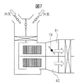
- FIG. It is explanatory drawing which shows other one Embodiment of an external air quantity adjustment mechanism.
- FIG. It is explanatory drawing which shows other one Embodiment (at the time of inside / outside air suction FOOT mode) of an outside air quantity adjustment mechanism. It is explanatory drawing which shows other one Embodiment (at the time of inside / outside air suction FOOT mode) of an outside air quantity adjustment mechanism. It is explanatory drawing which shows other one Embodiment of an external air quantity adjustment mechanism.
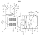
- FIG. 2 is a schematic explanatory diagram of the inside / outside air suction FOOT mode in an embodiment of the present invention.
- FIG. 3 is a schematic explanatory diagram of an outside air suction FOOT mode in an embodiment of the present invention.
- the vehicle air conditioner of the present invention is divided into two parts: an air conditioning unit 10 called HVAC and a blower unit 9 that blows air to the air conditioning unit 10.
- the blower unit 9 of the present embodiment has a two-layer structure that can blow inside air and outside air in two layers.
- the intake port switching door that opens and closes the air introduction port includes an inside air switching door 67 provided at the inside air introduction port 65, an outside air switching door 68 provided at the outside air introduction port 66, and an inside / outside air switching door 69.
- Inside / outside air suction mode (67: open, 68: open, 69: closed)
- outside air mode (67: closed, 68: open, 69: open)
- inside air mode (67: open, 68: closed, 69: open)
- the suction port switching door is not necessarily limited to the embodiment of FIG.
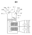
- FIG. 4 shows a modification of the suction port switching door of the present embodiment.
- 65-1 and 66-1 are outside air inlets, and 65-2 and 66-2 are inside air inlets.
- the switching doors 67 ′ and 68 ′ can be rotated to realize the inside / outside air suction mode, the outside air mode, and the inside air mode.
- Patent Document 2 There are various forms other than these (see Patent Document 2 as an example).
- the centrifugal blower 8 of the blower unit 9 includes an upper fan 52 and a lower fan 53.
- the upper fan and the lower fan are not limited to upper and lower terms.
- outside air passes through the first introduction passage 71 from the outside air introduction port 66, passes through the filter 90, and is sucked into the upper fan 52 from the upper introduction port 91. After that, it communicates with the defroster opening 26 and the face opening 28 via the first discharge passage 81.
- the inside air passes through the second introduction passage 70 from the inside air introduction port 65, passes through the filter 90, and is sucked into the lower fan 53 from the lower introduction port 92. Thereafter, the foot opening 30 communicates with the second discharge passage 82.
- the throttle door 72 Since the throttle door 72 is installed in the first introduction passage 71, the outside air is squeezed and blown to the defroster opening 26 and the face opening 28. Even if the vehicle speed increases and the ram pressure of the introduced outside air increases, the throttle door 72 can be adjusted to adjust the air volume blown from the defroster opening 26 and the face opening 28. As a result, even if the defroster door 27 and the face door 28 do not have a small opening, the airflow flowing on the upper side can be adjusted linearly. For this reason, it is possible to adjust to an appropriate air volume without impairing a feeling of comfort with respect to an increase in the air volume due to the ram pressure when the vehicle is operating at high speed while suppressing the generation of wind noise due to the minute opening of the door. .
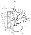
- FIG. 5 is a cross-sectional view of an air conditioning unit according to an embodiment of the present invention.
- This air conditioning unit is given as an example, and is not limited to this, and includes various modifications.
- the air mix doors 20 and 21 are slide doors, but may be a rotary door, and there are various embodiments of the air mix door and the passage route.
- the passage in the blower unit is divided into an upper (outside air side) air passage and a lower (inside air side) air passage by the first upstream partition member 15 and the first downstream partition member 22.
- HVAC blower unit
- the outside air suction FOOT mode will be described with reference to FIG.
- the inside air switching door 67 provided at the inside air introduction port 65 is closed, the outside air switching door 68 provided at the outside air introduction port 66 is opened, and the inside / outside air switching door 69 is also opened. Therefore, outside air is introduced into both the first introduction passage 71 and the second introduction passage 70. Since the throttle door 72 is installed in the first introduction passage 71, the outside air is squeezed through the defroster opening 26 and the face opening 28 and then blown. In the FOOT mode, the air volume hitting the occupant's face is not increased. Although the outside air is blown into the second introduction passage 70 without being throttled, the air is communicated with the foot opening 30 via the second discharge passage 82 and is blown to the feet, so even if the air volume increases, there is no problem. .
- This embodiment is effective in the FOOT mode.
- FOOT mode there are various variations in the form of the FOOT mode.
- FIG. 1B shows an example of the FOOT mode, such a FOOT mode may be used.
- a slight amount of air is blown also from the defroster opening 26 and the face opening 28.
- the present invention is not limited to this, and the effect of the present embodiment is exhibited as long as it is a mode that mainly distributes wind to the FOOT opening 30 (in this application, such a mode is referred to as a FOOT mode).
- a FOOT mode even in the F / D mode, there is an effect of blowing outside air.
- the throttle door 72 since the throttle door 72 is installed in front of the upper inlet 91 of the upper fan 52, the feeling of comfort is impaired against the increase in air volume due to ram pressure when the vehicle is operating at high speed. It can be adjusted to an appropriate air volume. Furthermore, the amount of work to be performed by the fan can be reduced, and an unexpected energy saving effect has been generated as noise is reduced.
- FIG. 6A is an explanatory view showing another embodiment of the outside air amount adjusting mechanism
- FIG. 6B is a schematic view showing an iris shutter type throttle door 75.
- the diameter of the circular hole 76 at the center can be changed by the plurality of blades 77, and the function as an aperture door is exhibited. It is good to install in the bell mouth part of the upper inlet 91 of the upper fan 52.
- the amount of air flowing through the first discharge passage 81 and the upper (outside air side) air passage is linearly adjusted. Thereby, it is possible to adjust to an appropriate air volume without impairing the comfort feeling against the increase in the air volume due to the ram pressure.
- the throttle door 78 is provided in the first discharge passage 81 from the upper fan 52 to the evaporator 12.
- the open / close door 79 is provided with a first discharge passage 81 from the upper fan 52 to the evaporator 12 and a second discharge from the lower fan 52 to the evaporator 12. It is an embodiment provided in the upper and lower passage partition member 73 between the passage 81. Since the opening / closing door 79 rotates toward the first discharge passage, the amount of air passing through the first discharge passage 81 can be reduced. Thereby, it is possible to adjust to an appropriate air volume without impairing the comfort feeling against the increase in the air volume due to the ram pressure.
- FIG. 9 is an explanatory view showing another embodiment of the outside air amount adjusting mechanism.
- a gap between the nose portion and the outer peripheral portion of the fan blade 84 is adjusted by a nose portion gap variable mechanism 83 provided in the nose portion of the upper fan 52.
- the gap between the nose portion and the fan blade outer peripheral portion is largely opened, the fan is idled and the amount of blown air is reduced. Thereby, it is possible to adjust to an appropriate air volume without impairing a feeling of comfort with respect to an increase in the air volume due to the ram pressure.
- the nose part gap variable mechanism 83 swings in FIG. 9 to adjust the gap amount, but is not limited thereto, and may be moved linearly.
- the fan is idled to reduce the amount of air blown and the work volume is also reduced, so that an energy saving effect is also produced.
- Blower unit 10 Air conditioning unit 26 Defroster opening 28 Face opening 30 Foot opening 52 Upper fan 53 Lower fan 70 Second introduction passage 71 First introduction passage 81 First discharge passage 82 Second discharge passage
Landscapes
- Physics & Mathematics (AREA)
- Thermal Sciences (AREA)
- Engineering & Computer Science (AREA)
- Mechanical Engineering (AREA)
- Air-Conditioning For Vehicles (AREA)
Abstract
Description
図2は、本発明の一実施形態における、内外気吸込みFOOTモードの概略説明図である。図3は、本発明の一実施形態における、外気吸込みFOOTモードの概略説明図である。図4は、本発明の一実施形態の吸込口切替ドア変形例における、内外気吸込みFOOTモードの概略説明図である。本発明の車両用空調装置は、HVACといわれる空調ユニット10と、この空調ユニット10に空気を送風する送風機ユニット9との2つの部分に分かれている。本実施形態の送風機ユニット9は、内気と外気を2層状態で送風できる2層構造である。
図4には本実施形態の吸込口切替ドアの変形例が示されている。図4において、65−1、66−1は、外気導入口であり、65−2、66−2は、内気導入口である。切替ドア67’、68’を回転して、内外気吸い込みモード、外気モード、内気モードを実現することができる。これら以外にも様々な形態が存在する(一例として、特許文献2参照)。
本発明は、例示を目的として選択された特定の実施態様を参照して記述されているが、当業者にとっては本発明の基礎概念とその開示範囲から逸脱せずに、数多くのモディフィケーションが為しうることが明らかであろう。
10 空調ユニット
26 デフロスタ開口部
28 フェイス開口部
30 フット開口部
52 上側ファン
53 下側ファン
70 第2導入通路
71 第1導入通路
81 第1吐出通路
82 第2吐出通路
Claims (8)
- 上側ファン(52)、下側ファン(53)、切替ドア(67、68、69、67’、68’)の切替により、内気又は外気を上側ファン(52)に吸込む第1導入通路(71)、内気又は外気を下側ファン(53)に吸込む第2導入通路(70)、及び、前記上側ファン(52)、前記下側ファン(53)からの送風空気をそれぞれ二層状態で吐出する、第1吐出通路(81)、第2吐出通路(82)を有する送風機ユニット(9)と、
前記送風機ユニット(9)からの送風空気を、蒸発器(12)、エアミックスドア、ヒータコア(13)により温度調整して、デフロスタ開口部(26)、フェイス開口部(28)、フット開口部(30)から車室内に空気を吹出す空調ユニット(10)と、
を具備する車両用空調装置において、
前記第1導入通路(71)は、内気と外気を分離して吸込むときには外気のみが導入される導入通路であって、前記第1導入通路(71)又はその下流に、車速に応じて外気送風量を制限する外気量調整機構を設けて、前記デフロスタ開口部(26)又は前記フェイス開口部(28)の風きり音の発生を抑制した車両用空調装置。 - 前記第1導入通路(71)と前記第2導入通路(70)は、内気と外気を分離して吸込む内外気2層モード、外気モード、内気モードの3通りの吸込みモードで、内気又は外気が導入されることを特徴とする請求項1に記載の車両用空調装置。
- 前記第1導入通路(71)が、前記デフロスタ開口部(26)、及び、前記フェイス開口部(28)に連通し、前記第2導入通路(70)が、前記フット開口部(30)に連通することを特徴とする請求項1又は2に記載の車両用空調装置。
- 前記外気量調整機構が、前記第1導入通路(71)に設けられた絞りドア(72)であることを特徴とする請求項1から3のいずれか1項に記載の車両用空調装置。
- 前記外気量調整機構が、前記第1導入通路(71)に設けられたアイリスシャッタ式絞りドア(75)であることを特徴とする請求項1から3のいずれか1項に記載の車両用空調装置。
- 前記外気量調整機構が、前記上側ファン(52)から前記蒸発器(12)に至る第1吐出通路(81)に設けられた絞りドア(78)であることを特徴とする請求項1から3のいずれか1項に記載の車両用空調装置。
- 前記外気量調整機構が、前記上側ファン(52)から前記蒸発器(12)に至る第1吐出通路(81)と前記下側ファン(52)から前記蒸発器(12)に至る第2吐出通路(81)との間の上下通路仕切り部材(73)に設けられた開閉ドア(79)であることを特徴とする請求項1から3のいずれか1項に記載の車両用空調装置。
- 前記外気量調整機構が、前記上側ファン(52)のノーズ部に設けられたノーズ部間隙可変機構(83)であることを特徴とする請求項1から3のいずれか1項に記載の車両用空調装置。
Priority Applications (3)
| Application Number | Priority Date | Filing Date | Title |
|---|---|---|---|
| DE112011104933.1T DE112011104933T5 (de) | 2011-02-22 | 2011-10-03 | Fahrzeugklimaanlagensystem |
| CN201180064448.4A CN103298632B (zh) | 2011-02-22 | 2011-10-03 | 车辆用空调装置 |
| US13/985,009 US20130319630A1 (en) | 2011-02-22 | 2011-10-03 | Vehicular air-conditioning system |
Applications Claiming Priority (2)
| Application Number | Priority Date | Filing Date | Title |
|---|---|---|---|
| JP2011035458A JP5625993B2 (ja) | 2011-02-22 | 2011-02-22 | 車両用空調装置 |
| JP2011-035458 | 2011-02-22 |
Publications (1)
| Publication Number | Publication Date |
|---|---|
| WO2012114573A1 true WO2012114573A1 (ja) | 2012-08-30 |
Family
ID=46720377
Family Applications (1)
| Application Number | Title | Priority Date | Filing Date |
|---|---|---|---|
| PCT/JP2011/073167 Ceased WO2012114573A1 (ja) | 2011-02-22 | 2011-10-03 | 車両用空調装置 |
Country Status (5)
| Country | Link |
|---|---|
| US (1) | US20130319630A1 (ja) |
| JP (1) | JP5625993B2 (ja) |
| CN (1) | CN103298632B (ja) |
| DE (1) | DE112011104933T5 (ja) |
| WO (1) | WO2012114573A1 (ja) |
Cited By (1)
| Publication number | Priority date | Publication date | Assignee | Title |
|---|---|---|---|---|
| FR3010660A1 (fr) * | 2013-09-19 | 2015-03-20 | Valeo Systemes Thermiques | Installation de chauffage, ventilation et/ou climatisation pour habitacle de vehicule automobile |
Families Citing this family (42)
| Publication number | Priority date | Publication date | Assignee | Title |
|---|---|---|---|---|
| US6889762B2 (en) | 2002-04-29 | 2005-05-10 | Bergstrom, Inc. | Vehicle air conditioning and heating system providing engine on and engine off operation |
| US9694651B2 (en) | 2002-04-29 | 2017-07-04 | Bergstrom, Inc. | Vehicle air conditioning and heating system providing engine on and off operation |
| US9636968B2 (en) * | 2011-12-26 | 2017-05-02 | Calsonic Kansei Corporation | Vehicle air conditioner including sub-casing sandwiched by division casings |
| DE102012004655B4 (de) | 2012-03-02 | 2023-08-31 | Valeo Klimasysteme Gmbh | Gebläsebaugruppe für eine Fahrzeugklimaanlage, Fahrzeugklimaanlage und Verfahren zum Betrieb einer Fahrzeugklimaanlage |
| EP2969613B1 (en) * | 2013-03-13 | 2018-08-08 | Bergstrom, Inc. | Air conditioning system utilizing heat recovery ventilation for fresh air supply and climate control |
| EP2969615B1 (en) | 2013-03-13 | 2021-06-02 | Bergstrom, Inc. | Air conditioning system utilizing thermal capacity from expansion of compressed fluid |
| JP5949677B2 (ja) * | 2013-06-14 | 2016-07-13 | 株式会社デンソー | 車両用空調装置 |
| KR102086380B1 (ko) * | 2013-08-22 | 2020-03-09 | 주식회사 두원공조 | 차량용 공기조화장치 |
| JP6015607B2 (ja) * | 2013-09-18 | 2016-10-26 | 株式会社デンソー | 車両用空調ユニット |
| FR3010656B1 (fr) * | 2013-09-19 | 2015-10-09 | Valeo Systemes Thermiques | Dispositif de conditionnement d'air pour vehicule automobile a double flux integrant un repartiteur de chaleur |
| JP2015083449A (ja) * | 2013-09-20 | 2015-04-30 | 株式会社デンソー | 空調ユニット |
| CN105873778A (zh) | 2013-11-04 | 2016-08-17 | 博格思众公司 | 低轮廓空调系统 |
| US9783024B2 (en) | 2015-03-09 | 2017-10-10 | Bergstrom Inc. | System and method for remotely managing climate control systems of a fleet of vehicles |
| JP6406442B2 (ja) * | 2015-04-24 | 2018-10-17 | 株式会社デンソー | 車両用空調ユニット |
| DE112016002278T5 (de) * | 2015-05-19 | 2018-02-15 | Denso Corporation | Klimatisierungsvorrichtung für Fahrzeug |
| US10166841B2 (en) * | 2015-09-09 | 2019-01-01 | International Truck Intellectual Property Company, Llc | Vehicle climate control system |
| WO2017047302A1 (ja) | 2015-09-15 | 2017-03-23 | 株式会社デンソー | エンジン制御装置、空調システム、および、空調制御装置に用いるプログラム |
| US10006684B2 (en) | 2015-12-10 | 2018-06-26 | Bergstrom, Inc. | Air conditioning system for use in vehicle |
| US9874384B2 (en) | 2016-01-13 | 2018-01-23 | Bergstrom, Inc. | Refrigeration system with superheating, sub-cooling and refrigerant charge level control |
| US10589598B2 (en) | 2016-03-09 | 2020-03-17 | Bergstrom, Inc. | Integrated condenser and compressor system |
| US12420616B2 (en) | 2016-08-22 | 2025-09-23 | Bergstrom, Inc. | Multi-compressor oil migration mitigation climate system |
| US10081226B2 (en) | 2016-08-22 | 2018-09-25 | Bergstrom Inc. | Parallel compressors climate system |
| US10562372B2 (en) | 2016-09-02 | 2020-02-18 | Bergstrom, Inc. | Systems and methods for starting-up a vehicular air-conditioning system |
| US10675948B2 (en) | 2016-09-29 | 2020-06-09 | Bergstrom, Inc. | Systems and methods for controlling a vehicle HVAC system |
| US10369863B2 (en) | 2016-09-30 | 2019-08-06 | Bergstrom, Inc. | Refrigerant liquid-gas separator with electronics cooling |
| US10724772B2 (en) | 2016-09-30 | 2020-07-28 | Bergstrom, Inc. | Refrigerant liquid-gas separator having an integrated check valve |
| WO2018083940A1 (ja) * | 2016-11-07 | 2018-05-11 | 株式会社デンソー | 車両用空調ユニット |
| EP3546256B1 (en) * | 2016-11-23 | 2020-06-24 | Denso Corporation | Vehicular air conditioning device |
| KR102474617B1 (ko) * | 2016-12-14 | 2022-12-06 | 현대자동차주식회사 | 자동차용 트리플 존 공기조화장치 |
| US20180170146A1 (en) * | 2016-12-16 | 2018-06-21 | Air International (Us) Inc. | Hvac system |
| US11448441B2 (en) | 2017-07-27 | 2022-09-20 | Bergstrom, Inc. | Refrigerant system for cooling electronics |
| US11420496B2 (en) | 2018-04-02 | 2022-08-23 | Bergstrom, Inc. | Integrated vehicular system for conditioning air and heating water |
| JP2019199130A (ja) * | 2018-05-15 | 2019-11-21 | 株式会社ヴァレオジャパン | 車両用空調装置 |
| JP7120932B2 (ja) * | 2019-01-09 | 2022-08-17 | マーレ インターナショナル ゲゼルシャフト ミット ベシュレンクテル ハフツング | 車両用空調装置 |
| JP7059952B2 (ja) | 2019-02-05 | 2022-04-26 | 株式会社デンソー | 車両用空調装置の送風ユニット |
| DE112020002446B4 (de) | 2019-05-21 | 2023-12-14 | Hanon Systems | Klimaanlage für ein Fahrzeug |
| DE102019219536A1 (de) * | 2019-12-13 | 2021-06-17 | Mahle International Gmbh | Belüftungsvorrichtung |
| US12173720B2 (en) * | 2020-03-05 | 2024-12-24 | Panasonic Intellectual Property Management Co., Ltd. | Identification method and air blowing system |
| JP7458267B2 (ja) * | 2020-08-19 | 2024-03-29 | 東京エレクトロン株式会社 | 基板処理装置及び基板搬送方法 |
| FR3114048B1 (fr) * | 2020-09-14 | 2022-12-30 | Valeo Systemes Thermiques | Module d’échange thermique et véhicule automobile correspondant |
| CN112882778A (zh) * | 2021-01-28 | 2021-06-01 | 湖北亿咖通科技有限公司 | 绘制车机空调显示界面的方法和计算机存储介质 |
| KR20240039875A (ko) * | 2022-09-20 | 2024-03-27 | 현대자동차주식회사 | 모빌리티용 공조 장치 |
Citations (4)
| Publication number | Priority date | Publication date | Assignee | Title |
|---|---|---|---|---|
| JPH0576813U (ja) * | 1992-03-30 | 1993-10-19 | 株式会社日本クライメイトシステムズ | 自動車用空調装置のブロアユニット |
| JPH0924723A (ja) * | 1995-05-10 | 1997-01-28 | Nippondenso Co Ltd | 車両用空調装置 |
| JP2000296710A (ja) * | 1999-04-15 | 2000-10-24 | Mitsubishi Heavy Ind Ltd | 空気調和ユニット及び車両用空気調和装置 |
| JP2003165322A (ja) * | 2001-11-28 | 2003-06-10 | Denso Corp | 車両用空調装置 |
Family Cites Families (15)
| Publication number | Priority date | Publication date | Assignee | Title |
|---|---|---|---|---|
| JPS6227444Y2 (ja) * | 1981-01-28 | 1987-07-14 | ||
| US5309731A (en) * | 1991-12-27 | 1994-05-10 | Nippondenso Co., Ltd. | Air conditioning apparatus |
| JP3222375B2 (ja) * | 1995-03-20 | 2001-10-29 | トヨタ自動車株式会社 | 車両用空気調和装置 |
| US7082990B1 (en) * | 1996-06-13 | 2006-08-01 | Denso Corporation | Air conditioning apparatus for vehicle |
| US6352102B1 (en) * | 1996-10-07 | 2002-03-05 | Denso Corporation | Air conditioning apparatus for vehicle |
| DE19705629C2 (de) * | 1997-02-14 | 2002-12-12 | Audi Ag | Heiz- oder Klimaanlage für Kraftfahrzeuge |
| FR2774035B1 (fr) * | 1998-01-29 | 2000-03-31 | Valeo Climatisation | Dispositif de chauffage et/ou climatisation de vehicule automobile, avec gestion amelioree de l'echange thermique |
| US6192698B1 (en) * | 1998-03-12 | 2001-02-27 | Denso Corporation | Vehicle-air-conditioning system with cooling degree estimator for left/right temperature control |
| JP3269467B2 (ja) * | 1998-10-28 | 2002-03-25 | 株式会社デンソー | 車両用空調装置 |
| JP2000289436A (ja) * | 1999-04-09 | 2000-10-17 | Mitsubishi Heavy Ind Ltd | 車両用空気調和装置 |
| KR100601835B1 (ko) * | 1999-12-30 | 2006-07-19 | 한라공조주식회사 | 자동차용 공기조화장치 |
| EP1500532B1 (en) * | 2003-07-25 | 2008-10-29 | Delphi Technologies, Inc. | Air conditioning module |
| JP2008049782A (ja) * | 2006-08-23 | 2008-03-06 | Calsonic Kansei Corp | 車両用空調装置 |
| KR20100064609A (ko) * | 2008-12-05 | 2010-06-15 | 현대자동차주식회사 | 차량용 공기조화기의 공기유입방법 및 그 시스템 |
| US8939823B2 (en) * | 2011-02-21 | 2015-01-27 | Honda Motor Co., Ltd. | Vehicle HVAC system with ram pressure control |
-
2011
- 2011-02-22 JP JP2011035458A patent/JP5625993B2/ja not_active Expired - Fee Related
- 2011-10-03 WO PCT/JP2011/073167 patent/WO2012114573A1/ja not_active Ceased
- 2011-10-03 US US13/985,009 patent/US20130319630A1/en not_active Abandoned
- 2011-10-03 CN CN201180064448.4A patent/CN103298632B/zh not_active Expired - Fee Related
- 2011-10-03 DE DE112011104933.1T patent/DE112011104933T5/de not_active Withdrawn
Patent Citations (4)
| Publication number | Priority date | Publication date | Assignee | Title |
|---|---|---|---|---|
| JPH0576813U (ja) * | 1992-03-30 | 1993-10-19 | 株式会社日本クライメイトシステムズ | 自動車用空調装置のブロアユニット |
| JPH0924723A (ja) * | 1995-05-10 | 1997-01-28 | Nippondenso Co Ltd | 車両用空調装置 |
| JP2000296710A (ja) * | 1999-04-15 | 2000-10-24 | Mitsubishi Heavy Ind Ltd | 空気調和ユニット及び車両用空気調和装置 |
| JP2003165322A (ja) * | 2001-11-28 | 2003-06-10 | Denso Corp | 車両用空調装置 |
Cited By (2)
| Publication number | Priority date | Publication date | Assignee | Title |
|---|---|---|---|---|
| FR3010660A1 (fr) * | 2013-09-19 | 2015-03-20 | Valeo Systemes Thermiques | Installation de chauffage, ventilation et/ou climatisation pour habitacle de vehicule automobile |
| WO2015039924A1 (fr) * | 2013-09-19 | 2015-03-26 | Valeo Systemes Thermiques | Installation de chauffage, ventilation et/ou climatisation pour habitacle de véhicule automobile |
Also Published As
| Publication number | Publication date |
|---|---|
| JP5625993B2 (ja) | 2014-11-19 |
| CN103298632B (zh) | 2016-01-20 |
| US20130319630A1 (en) | 2013-12-05 |
| DE112011104933T5 (de) | 2014-03-06 |
| JP2012171489A (ja) | 2012-09-10 |
| CN103298632A (zh) | 2013-09-11 |
Similar Documents
| Publication | Publication Date | Title |
|---|---|---|
| JP5625993B2 (ja) | 車両用空調装置 | |
| JP4424409B2 (ja) | 車両用空調装置 | |
| CN105517819B (zh) | 车辆用空调单元 | |
| JP5569513B2 (ja) | 車両用空調装置 | |
| JP5482720B2 (ja) | 車両用空調装置 | |
| JPH10230734A (ja) | 車両用空調装置 | |
| CN105517822A (zh) | 空调单元 | |
| JP2010100140A (ja) | 車両用空調装置 | |
| CN105189158B (zh) | 车辆用空调装置 | |
| CN103847462A (zh) | 车辆的后部空调 | |
| JP2017149307A (ja) | 車両用空気吹き出し装置 | |
| JP2002331819A (ja) | 車両用空調装置 | |
| CN105939875B (zh) | 车辆用空调装置 | |
| WO2018083940A1 (ja) | 車両用空調ユニット | |
| JP5924230B2 (ja) | 空調装置 | |
| CN108778794B (zh) | 车辆用空调装置 | |
| JP4178866B2 (ja) | 車両用空調装置 | |
| KR101492152B1 (ko) | 차량용 후석 공조장치 | |
| JP2004314759A (ja) | 車両用空調装置 | |
| JPS61188214A (ja) | 自動車用空調装置 | |
| JP4007158B2 (ja) | 車両用空調装置 | |
| JP4687435B2 (ja) | 車両用空調装置 | |
| KR101566307B1 (ko) | 차량용 후석 공조장치 | |
| JP4624773B2 (ja) | 車両用空調装置 | |
| JP4130185B2 (ja) | 車両用空調装置 |
Legal Events
| Date | Code | Title | Description |
|---|---|---|---|
| 121 | Ep: the epo has been informed by wipo that ep was designated in this application |
Ref document number: 11859077 Country of ref document: EP Kind code of ref document: A1 |
|
| WWE | Wipo information: entry into national phase |
Ref document number: 13985009 Country of ref document: US |
|
| WWE | Wipo information: entry into national phase |
Ref document number: 112011104933 Country of ref document: DE Ref document number: 1120111049331 Country of ref document: DE |
|
| 122 | Ep: pct application non-entry in european phase |
Ref document number: 11859077 Country of ref document: EP Kind code of ref document: A1 |