WO2012111730A1 - 車両用制動制御装置 - Google Patents
車両用制動制御装置 Download PDFInfo
- Publication number
- WO2012111730A1 WO2012111730A1 PCT/JP2012/053610 JP2012053610W WO2012111730A1 WO 2012111730 A1 WO2012111730 A1 WO 2012111730A1 JP 2012053610 W JP2012053610 W JP 2012053610W WO 2012111730 A1 WO2012111730 A1 WO 2012111730A1
- Authority
- WO
- WIPO (PCT)
- Prior art keywords
- operation amount
- hydraulic pressure
- brake
- brake operation
- servo characteristic
- Prior art date
- Legal status (The legal status is an assumption and is not a legal conclusion. Google has not performed a legal analysis and makes no representation as to the accuracy of the status listed.)
- Ceased
Links
Images




Classifications
-
- B—PERFORMING OPERATIONS; TRANSPORTING
- B60—VEHICLES IN GENERAL
- B60T—VEHICLE BRAKE CONTROL SYSTEMS OR PARTS THEREOF; BRAKE CONTROL SYSTEMS OR PARTS THEREOF, IN GENERAL; ARRANGEMENT OF BRAKING ELEMENTS ON VEHICLES IN GENERAL; PORTABLE DEVICES FOR PREVENTING UNWANTED MOVEMENT OF VEHICLES; VEHICLE MODIFICATIONS TO FACILITATE COOLING OF BRAKES
- B60T11/00—Transmitting braking action from initiating means to ultimate brake actuator without power assistance or drive or where such assistance or drive is irrelevant
- B60T11/10—Transmitting braking action from initiating means to ultimate brake actuator without power assistance or drive or where such assistance or drive is irrelevant transmitting by fluid means, e.g. hydraulic
- B60T11/16—Master control, e.g. master cylinders
-
- B—PERFORMING OPERATIONS; TRANSPORTING
- B60—VEHICLES IN GENERAL
- B60T—VEHICLE BRAKE CONTROL SYSTEMS OR PARTS THEREOF; BRAKE CONTROL SYSTEMS OR PARTS THEREOF, IN GENERAL; ARRANGEMENT OF BRAKING ELEMENTS ON VEHICLES IN GENERAL; PORTABLE DEVICES FOR PREVENTING UNWANTED MOVEMENT OF VEHICLES; VEHICLE MODIFICATIONS TO FACILITATE COOLING OF BRAKES
- B60T13/00—Transmitting braking action from initiating means to ultimate brake actuator with power assistance or drive; Brake systems incorporating such transmitting means, e.g. air-pressure brake systems
- B60T13/10—Transmitting braking action from initiating means to ultimate brake actuator with power assistance or drive; Brake systems incorporating such transmitting means, e.g. air-pressure brake systems with fluid assistance, drive, or release
- B60T13/12—Transmitting braking action from initiating means to ultimate brake actuator with power assistance or drive; Brake systems incorporating such transmitting means, e.g. air-pressure brake systems with fluid assistance, drive, or release the fluid being liquid
- B60T13/14—Transmitting braking action from initiating means to ultimate brake actuator with power assistance or drive; Brake systems incorporating such transmitting means, e.g. air-pressure brake systems with fluid assistance, drive, or release the fluid being liquid using accumulators or reservoirs fed by pumps
- B60T13/142—Systems with master cylinder
- B60T13/147—In combination with distributor valve
-
- B—PERFORMING OPERATIONS; TRANSPORTING
- B60—VEHICLES IN GENERAL
- B60T—VEHICLE BRAKE CONTROL SYSTEMS OR PARTS THEREOF; BRAKE CONTROL SYSTEMS OR PARTS THEREOF, IN GENERAL; ARRANGEMENT OF BRAKING ELEMENTS ON VEHICLES IN GENERAL; PORTABLE DEVICES FOR PREVENTING UNWANTED MOVEMENT OF VEHICLES; VEHICLE MODIFICATIONS TO FACILITATE COOLING OF BRAKES
- B60T11/00—Transmitting braking action from initiating means to ultimate brake actuator without power assistance or drive or where such assistance or drive is irrelevant
- B60T11/10—Transmitting braking action from initiating means to ultimate brake actuator without power assistance or drive or where such assistance or drive is irrelevant transmitting by fluid means, e.g. hydraulic
- B60T11/16—Master control, e.g. master cylinders
- B60T11/20—Tandem, side-by-side, or other multiple master cylinder units
-
- B—PERFORMING OPERATIONS; TRANSPORTING
- B60—VEHICLES IN GENERAL
- B60T—VEHICLE BRAKE CONTROL SYSTEMS OR PARTS THEREOF; BRAKE CONTROL SYSTEMS OR PARTS THEREOF, IN GENERAL; ARRANGEMENT OF BRAKING ELEMENTS ON VEHICLES IN GENERAL; PORTABLE DEVICES FOR PREVENTING UNWANTED MOVEMENT OF VEHICLES; VEHICLE MODIFICATIONS TO FACILITATE COOLING OF BRAKES
- B60T13/00—Transmitting braking action from initiating means to ultimate brake actuator with power assistance or drive; Brake systems incorporating such transmitting means, e.g. air-pressure brake systems
- B60T13/10—Transmitting braking action from initiating means to ultimate brake actuator with power assistance or drive; Brake systems incorporating such transmitting means, e.g. air-pressure brake systems with fluid assistance, drive, or release
- B60T13/12—Transmitting braking action from initiating means to ultimate brake actuator with power assistance or drive; Brake systems incorporating such transmitting means, e.g. air-pressure brake systems with fluid assistance, drive, or release the fluid being liquid
- B60T13/14—Transmitting braking action from initiating means to ultimate brake actuator with power assistance or drive; Brake systems incorporating such transmitting means, e.g. air-pressure brake systems with fluid assistance, drive, or release the fluid being liquid using accumulators or reservoirs fed by pumps
- B60T13/142—Systems with master cylinder
- B60T13/145—Master cylinder integrated or hydraulically coupled with booster
-
- B—PERFORMING OPERATIONS; TRANSPORTING
- B60—VEHICLES IN GENERAL
- B60T—VEHICLE BRAKE CONTROL SYSTEMS OR PARTS THEREOF; BRAKE CONTROL SYSTEMS OR PARTS THEREOF, IN GENERAL; ARRANGEMENT OF BRAKING ELEMENTS ON VEHICLES IN GENERAL; PORTABLE DEVICES FOR PREVENTING UNWANTED MOVEMENT OF VEHICLES; VEHICLE MODIFICATIONS TO FACILITATE COOLING OF BRAKES
- B60T13/00—Transmitting braking action from initiating means to ultimate brake actuator with power assistance or drive; Brake systems incorporating such transmitting means, e.g. air-pressure brake systems
- B60T13/10—Transmitting braking action from initiating means to ultimate brake actuator with power assistance or drive; Brake systems incorporating such transmitting means, e.g. air-pressure brake systems with fluid assistance, drive, or release
- B60T13/12—Transmitting braking action from initiating means to ultimate brake actuator with power assistance or drive; Brake systems incorporating such transmitting means, e.g. air-pressure brake systems with fluid assistance, drive, or release the fluid being liquid
- B60T13/14—Transmitting braking action from initiating means to ultimate brake actuator with power assistance or drive; Brake systems incorporating such transmitting means, e.g. air-pressure brake systems with fluid assistance, drive, or release the fluid being liquid using accumulators or reservoirs fed by pumps
- B60T13/142—Systems with master cylinder
- B60T13/145—Master cylinder integrated or hydraulically coupled with booster
- B60T13/146—Part of the system directly actuated by booster pressure
-
- B—PERFORMING OPERATIONS; TRANSPORTING
- B60—VEHICLES IN GENERAL
- B60T—VEHICLE BRAKE CONTROL SYSTEMS OR PARTS THEREOF; BRAKE CONTROL SYSTEMS OR PARTS THEREOF, IN GENERAL; ARRANGEMENT OF BRAKING ELEMENTS ON VEHICLES IN GENERAL; PORTABLE DEVICES FOR PREVENTING UNWANTED MOVEMENT OF VEHICLES; VEHICLE MODIFICATIONS TO FACILITATE COOLING OF BRAKES
- B60T13/00—Transmitting braking action from initiating means to ultimate brake actuator with power assistance or drive; Brake systems incorporating such transmitting means, e.g. air-pressure brake systems
- B60T13/10—Transmitting braking action from initiating means to ultimate brake actuator with power assistance or drive; Brake systems incorporating such transmitting means, e.g. air-pressure brake systems with fluid assistance, drive, or release
- B60T13/66—Electrical control in fluid-pressure brake systems
- B60T13/662—Electrical control in fluid-pressure brake systems characterised by specified functions of the control system components
-
- B—PERFORMING OPERATIONS; TRANSPORTING
- B60—VEHICLES IN GENERAL
- B60T—VEHICLE BRAKE CONTROL SYSTEMS OR PARTS THEREOF; BRAKE CONTROL SYSTEMS OR PARTS THEREOF, IN GENERAL; ARRANGEMENT OF BRAKING ELEMENTS ON VEHICLES IN GENERAL; PORTABLE DEVICES FOR PREVENTING UNWANTED MOVEMENT OF VEHICLES; VEHICLE MODIFICATIONS TO FACILITATE COOLING OF BRAKES
- B60T13/00—Transmitting braking action from initiating means to ultimate brake actuator with power assistance or drive; Brake systems incorporating such transmitting means, e.g. air-pressure brake systems
- B60T13/10—Transmitting braking action from initiating means to ultimate brake actuator with power assistance or drive; Brake systems incorporating such transmitting means, e.g. air-pressure brake systems with fluid assistance, drive, or release
- B60T13/66—Electrical control in fluid-pressure brake systems
- B60T13/68—Electrical control in fluid-pressure brake systems by electrically-controlled valves
- B60T13/686—Electrical control in fluid-pressure brake systems by electrically-controlled valves in hydraulic systems or parts thereof
-
- B—PERFORMING OPERATIONS; TRANSPORTING
- B60—VEHICLES IN GENERAL
- B60T—VEHICLE BRAKE CONTROL SYSTEMS OR PARTS THEREOF; BRAKE CONTROL SYSTEMS OR PARTS THEREOF, IN GENERAL; ARRANGEMENT OF BRAKING ELEMENTS ON VEHICLES IN GENERAL; PORTABLE DEVICES FOR PREVENTING UNWANTED MOVEMENT OF VEHICLES; VEHICLE MODIFICATIONS TO FACILITATE COOLING OF BRAKES
- B60T7/00—Brake-action initiating means
- B60T7/02—Brake-action initiating means for personal initiation
- B60T7/04—Brake-action initiating means for personal initiation foot actuated
- B60T7/042—Brake-action initiating means for personal initiation foot actuated by electrical means, e.g. using travel or force sensors
-
- B—PERFORMING OPERATIONS; TRANSPORTING
- B60—VEHICLES IN GENERAL
- B60T—VEHICLE BRAKE CONTROL SYSTEMS OR PARTS THEREOF; BRAKE CONTROL SYSTEMS OR PARTS THEREOF, IN GENERAL; ARRANGEMENT OF BRAKING ELEMENTS ON VEHICLES IN GENERAL; PORTABLE DEVICES FOR PREVENTING UNWANTED MOVEMENT OF VEHICLES; VEHICLE MODIFICATIONS TO FACILITATE COOLING OF BRAKES
- B60T8/00—Arrangements for adjusting wheel-braking force to meet varying vehicular or ground-surface conditions, e.g. limiting or varying distribution of braking force
- B60T8/32—Arrangements for adjusting wheel-braking force to meet varying vehicular or ground-surface conditions, e.g. limiting or varying distribution of braking force responsive to a speed condition, e.g. acceleration or deceleration
- B60T8/34—Arrangements for adjusting wheel-braking force to meet varying vehicular or ground-surface conditions, e.g. limiting or varying distribution of braking force responsive to a speed condition, e.g. acceleration or deceleration having a fluid pressure regulator responsive to a speed condition
- B60T8/40—Arrangements for adjusting wheel-braking force to meet varying vehicular or ground-surface conditions, e.g. limiting or varying distribution of braking force responsive to a speed condition, e.g. acceleration or deceleration having a fluid pressure regulator responsive to a speed condition comprising an additional fluid circuit including fluid pressurising means for modifying the pressure of the braking fluid, e.g. including wheel driven pumps for detecting a speed condition, or pumps which are controlled by means independent of the braking system
- B60T8/4072—Systems in which a driver input signal is used as a control signal for the additional fluid circuit which is normally used for braking
- B60T8/4077—Systems in which the booster is used as an auxiliary pressure source
-
- B—PERFORMING OPERATIONS; TRANSPORTING
- B60—VEHICLES IN GENERAL
- B60T—VEHICLE BRAKE CONTROL SYSTEMS OR PARTS THEREOF; BRAKE CONTROL SYSTEMS OR PARTS THEREOF, IN GENERAL; ARRANGEMENT OF BRAKING ELEMENTS ON VEHICLES IN GENERAL; PORTABLE DEVICES FOR PREVENTING UNWANTED MOVEMENT OF VEHICLES; VEHICLE MODIFICATIONS TO FACILITATE COOLING OF BRAKES
- B60T8/00—Arrangements for adjusting wheel-braking force to meet varying vehicular or ground-surface conditions, e.g. limiting or varying distribution of braking force
- B60T8/32—Arrangements for adjusting wheel-braking force to meet varying vehicular or ground-surface conditions, e.g. limiting or varying distribution of braking force responsive to a speed condition, e.g. acceleration or deceleration
- B60T8/34—Arrangements for adjusting wheel-braking force to meet varying vehicular or ground-surface conditions, e.g. limiting or varying distribution of braking force responsive to a speed condition, e.g. acceleration or deceleration having a fluid pressure regulator responsive to a speed condition
- B60T8/40—Arrangements for adjusting wheel-braking force to meet varying vehicular or ground-surface conditions, e.g. limiting or varying distribution of braking force responsive to a speed condition, e.g. acceleration or deceleration having a fluid pressure regulator responsive to a speed condition comprising an additional fluid circuit including fluid pressurising means for modifying the pressure of the braking fluid, e.g. including wheel driven pumps for detecting a speed condition, or pumps which are controlled by means independent of the braking system
- B60T8/4072—Systems in which a driver input signal is used as a control signal for the additional fluid circuit which is normally used for braking
- B60T8/4081—Systems with stroke simulating devices for driver input
- B60T8/4086—Systems with stroke simulating devices for driver input the stroke simulating device being connected to, or integrated in the driver input device
-
- B—PERFORMING OPERATIONS; TRANSPORTING
- B60—VEHICLES IN GENERAL
- B60T—VEHICLE BRAKE CONTROL SYSTEMS OR PARTS THEREOF; BRAKE CONTROL SYSTEMS OR PARTS THEREOF, IN GENERAL; ARRANGEMENT OF BRAKING ELEMENTS ON VEHICLES IN GENERAL; PORTABLE DEVICES FOR PREVENTING UNWANTED MOVEMENT OF VEHICLES; VEHICLE MODIFICATIONS TO FACILITATE COOLING OF BRAKES
- B60T2270/00—Further aspects of brake control systems not otherwise provided for
- B60T2270/60—Regenerative braking
- B60T2270/604—Merging friction therewith; Adjusting their repartition
Definitions
- the present invention relates to a vehicle brake control device that controls a braking force applied to a vehicle in accordance with a brake operation amount, and in particular, reduces an invalid operation amount that does not increase a braking force even when a driver depresses a brake pedal in a high deceleration region.
- the present invention relates to a vehicle braking control apparatus.
- Patent Document 1 there is a device described in Patent Document 1 as a vehicle braking control device.
- an input piston and an output piston are slidably fitted in a cylinder, and the output piston can be pressed by the input piston.
- the operation amount of a brake pedal connected to the input piston is reduced.
- the brake hydraulic pressure is supplied to the wheel cylinder that brakes the wheel.
- the brake fluid pressure corresponding to the operation amount of the brake pedal is supplied from the output piston to the wheel cylinder by pushing the output piston directly from the brake pedal via the input piston.
- braking force is properly applied to the wheels to improve safety.
- the present invention has been made in view of such circumstances, so as not to make the driver feel uncomfortable by reducing as much as possible the invalid operation amount at which the brake fluid pressure to the wheel cylinder does not increase when the brake operation amount increases. It is an object of the present invention to provide a vehicle brake control device that can perform the above-described operation.
- the structural feature of the invention according to claim 1 made to achieve the above object is that an input piston that slides in a cylinder in conjunction with a brake operation member, and the input piston are separated, and the brake operation member Is connected to a drive hydraulic chamber formed in the master cylinder, and a master cylinder having an output piston that slides in or contacts the input piston by the operation of A drive hydraulic pressure adjusting device that adjusts a drive hydraulic pressure that is a hydraulic pressure in a hydraulic pressure chamber within a range not exceeding a predetermined assisting limit hydraulic pressure, and in a state in which the input piston is separated from the output piston
- the master hydraulic pressure which is the hydraulic pressure in the master hydraulic pressure chamber formed in the master cylinder, is changed.
- the master hydraulic pressure changes as the input piston and the output piston slide in the cylinder in conjunction with the brake operation member.
- the drive hydraulic pressure adjusting device drives the drive so that the output piston is separated from the input piston.
- a brake operation amount detection means for detecting an operation amount of the brake operation member, and a brake operation that is an operation amount of the brake operation member detected by the brake operation amount detection means.
- the first servo characteristic is more than the first servo characteristic.
- Drive hydraulic pressure control means for controlling the drive hydraulic pressure by the drive hydraulic pressure adjusting device based on a second servo characteristic in which the increase in the drive hydraulic pressure is small relative to the increase in the brake operation amount, and the servo
- the characteristic change operation amount is obtained when the drive hydraulic pressure is increased according to the increase in the brake operation amount based on the first servo characteristic regardless of the brake operation amount. That is, the operation amount is set to be smaller than the assist limit operation amount that is the operation amount of the brake operation member that becomes the hydraulic pressure.
- the structural feature of the invention according to claim 2 is a state in which the hydraulic pressure difference is calculated by subtracting the drive hydraulic pressure in the servo characteristic changing operation amount from the assist limit hydraulic pressure, and the input piston and the output piston are separated from each other.
- a second servo characteristic setting unit configured to set a value as the second servo characteristic; and the drive hydraulic pressure control unit is configured to perform the brake operation based on the second servo characteristic set by the second servo characteristic setting unit.
- the drive hydraulic pressure control is performed when the amount is equal to or greater than the servo characteristic changing operation amount.
- the structural feature of the invention according to claim 3 is that, in the relationship between the brake operation amount and the master hydraulic pressure, a characteristic line at the time of driving hydraulic pressure control based on the first servo characteristic and the input piston are the output piston.
- Servo characteristic change operation amount setting means for setting the brake operation amount at the intersection with the characteristic line in the state of contact as the servo characteristic change operation amount, and the drive hydraulic pressure control means includes the servo characteristic change operation amount.
- the drive hydraulic pressure control is performed based on the servo characteristic changing operation amount set by the setting means.
- the structural feature of the invention according to claim 4 is that the master hydraulic pressure detecting means for detecting the master hydraulic pressure, and the increase of the master hydraulic pressure detected by the master hydraulic pressure detecting means with respect to the increase amount of the brake operation amount.
- Contact brake operation amount calculation means for calculating the contact brake operation amount based on a large amount is provided, and the second servo characteristic setting means is a contact brake operation amount calculated by the contact brake operation amount calculation means. The second servo characteristic is set based on the above.
- the structural feature of the invention according to claim 5 is that the master hydraulic pressure detecting means for detecting the master hydraulic pressure, and the master hydraulic pressure chamber is sent out from the master hydraulic pressure chamber based on the master hydraulic pressure detected by the master hydraulic pressure detecting means.
- a contact brake operation amount calculation means for calculating a fluid amount of the brake fluid applied and calculating a value obtained by dividing the fluid amount by a sectional area of the output piston and adding a predetermined value as the contact brake operation amount
- the second servo characteristic setting means sets the second servo characteristic based on the contact brake operation amount calculated by the contact brake operation amount calculation means.
- the structural feature of the invention according to claim 6 is provided with drive hydraulic pressure change determining means for determining whether or not the drive hydraulic pressure reaches the assist limit hydraulic pressure, and the drive hydraulic pressure control means When it is determined by the hydraulic pressure change determination means that the driving hydraulic pressure reaches the assisting limit hydraulic pressure, the change from the first servo characteristic to the second servo characteristic is performed.
- the present invention relates to an input piston that slides in a cylinder in conjunction with a brake operation member, and an output that is separated from the input piston and is separated or abutted against the input piston by operation of the brake operation member and slides in the cylinder.
- a master cylinder having a piston and a drive hydraulic pressure chamber that is connected to a drive hydraulic pressure chamber formed in the master cylinder and does not exceed a predetermined assist limit hydraulic pressure.
- a drive hydraulic pressure adjustment device that adjusts within the range, and when the input piston is separated from the output piston, the output piston is driven by the drive hydraulic pressure and slides in the cylinder to form the master cylinder.
- the input piston When the master hydraulic pressure that is the hydraulic pressure in the master hydraulic pressure chamber is changed and the input piston is in contact with the output piston, the input piston and the output piston This is applied to a vehicular braking device in which the master hydraulic pressure changes by sliding in the cylinder in conjunction with the material, and when the drive hydraulic pressure does not exceed the assist limit hydraulic pressure, the output piston is applied to the input piston.
- the vehicle brake control device controls the drive hydraulic pressure by the drive hydraulic pressure adjusting device so as to be separated from the vehicle.
- the brake operation member is interlocked.
- the input piston to be moved comes close to the output piston driven by the drive hydraulic pressure, and thus contacts the output piston.
- the input piston and the output piston are interlocked with the brake operation member, and the master hydraulic pressure increases.
- the output piston does not slide in the cylinder and the master hydraulic pressure does not change even if the operation amount of the brake operation member is maintained until it abuts on the cylinder. As a result, there is a concern that the driver may feel uncomfortable that the braking force does not increase even though the operation amount of the brake operation member is increased.
- the drive hydraulic pressure increases with respect to the increase amount of the operation amount of the brake operation member.
- the drive hydraulic pressure is controlled by the drive hydraulic pressure adjusting device on the basis of the first servo characteristic whose large amount is a predetermined value, and the brake operation amount is equal to or greater than the servo characteristic change operation amount, the brake is more effective than the first servo characteristic.
- the drive hydraulic pressure is controlled by the drive hydraulic pressure adjusting device based on the second servo characteristic in which the increase amount of the drive hydraulic pressure with respect to the increase amount of the operation amount is small.
- the servo hydraulic pressure change operation amount is set to the assist limit.
- the operation amount is set to be smaller than the assist limit operation amount that is the operation amount of the brake operation member that becomes the hydraulic pressure.
- the driving hydraulic pressure reaches the assisting limit hydraulic pressure as compared with the case where the driving hydraulic pressure is increased according to the increase in the operating amount of the brake operating member based on the first servo characteristic regardless of the operating amount of the brake operating member.
- the operation amount of the brake operation member increases, and the operation amount of the brake operation member from when the drive hydraulic pressure reaches the assisting limit hydraulic pressure until the input piston contacts the output piston decreases. As a result, it is possible to reduce the uncomfortable feeling that the braking force does not increase even though the operation amount of the brake operation member is increased.
- the second servo characteristic setting means calculates the hydraulic pressure difference by subtracting the driving hydraulic pressure at the servo characteristic changing operation amount from the assist limit hydraulic pressure, and the input piston and the output piston are separated from each other.
- the drive hydraulic pressure control means performs the drive hydraulic pressure control when the brake operation amount is equal to or larger than the servo characteristic change operation amount based on the second servo characteristic set by the second servo characteristic setting means. The position where the amount reaches the assisting limit hydraulic pressure can be appropriately set so that the invalid operation amount becomes small.
- the characteristic line and the input piston at the time of the driving hydraulic pressure control based on the first servo characteristic in the relationship between the brake operation amount and the master hydraulic pressure by the servo characteristic changing operation amount setting means are the output piston.
- the brake operation amount at the intersection with the characteristic line in the state of being in contact with is set as the servo characteristic change operation amount. Since the drive hydraulic pressure control means performs the drive hydraulic pressure control based on the servo characteristic change operation amount set by the servo characteristic change operation amount setting means, the position where the brake operation amount reaches the assist limit hydraulic pressure is It is possible to appropriately set so that the invalid operation amount is substantially eliminated.
- the contact brake operation amount calculation means calculates the contact brake operation amount based on the increase amount of the master hydraulic pressure detected by the master hydraulic pressure detection means with respect to the increase amount of the brake operation amount. calculate. Then, the second servo characteristic setting means sets the second servo characteristic based on the contact brake operation amount calculated by the contact brake operation amount calculation means. Therefore, based on the second servo characteristic, the position at which the contact brake operation amount reaches the assist limit hydraulic pressure can be appropriately set.
- the contact brake operation amount calculation means calculates the amount of brake fluid sent from the master hydraulic pressure chamber based on the master hydraulic pressure detected by the master hydraulic pressure detection means, A value obtained by adding the predetermined value to the value obtained by dividing the liquid amount by the cross-sectional area of the output piston is calculated as the contact brake operation amount. Then, the second servo characteristic setting means sets the second servo characteristic based on the contact brake operation amount calculated by the contact brake operation amount calculation means. Therefore, the position at which the contact brake operation amount reaches the assist limit hydraulic pressure can be appropriately set based on the second servo characteristic.
- the driving hydraulic pressure change determining means determines whether or not the driving hydraulic pressure reaches the assist limit hydraulic pressure.
- the drive hydraulic pressure control means determines that the drive hydraulic pressure reaches the assisting limit hydraulic pressure by the drive hydraulic pressure change determination means, the change from the first servo characteristic to the second servo characteristic is performed.
- the operation amount of the brake operation member from when the driving hydraulic pressure reaches the assisting limit hydraulic pressure until the input piston contacts the output piston is reduced. Can do.
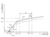
- FIG. 5 is a brake operation amount-target braking force map showing a relationship between a brake operation amount and a target braking force in the vehicle brake control device of the present embodiment.
- 3 is a hydraulic pressure-hydraulic braking force map showing a relationship between hydraulic fluid pressure and hydraulic braking force. It is a hydraulic-pressure graph which shows the liquid quantity sent from the cylinder until the hydraulic pressure which acts on an output piston becomes each hydraulic pressure. It is a figure which shows the modification of a hydraulic pressure-hydraulic braking force map.
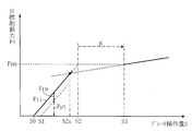
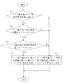
- FIG. 7 is a flowchart for preventing a change from a set servo characteristic to an invalid operation quantity reducing servo characteristic when it is determined that the brake operation quantity does not exceed the assist limit operation quantity. It is a figure which shows the invalid operation amount in the relationship between the conventional brake operation amount and braking force.
- the vehicle braking control device is mounted on, for example, a hybrid vehicle, and includes a cylinder 11 having a cylindrical shape with a base end opened and a tip end closed as shown in FIG. Inside the cylinder 11, an input piston 12, first and second output pistons 13 and 14 are arranged coaxially in order from the base end portion, and are slidably fitted along the axial direction. A part of the input piston 12 protrudes outward from the base end of the cylinder 11, and an operating rod 16 of the brake pedal 15 is connected to the protruding portion using a pivot 16a, and the brake pedal 15 is operated by a driver. It is movable via the operation rod 16. The movement amount of the brake pedal 15 is also referred to as a brake operation amount.
- the input piston 12 is slidably fitted in an input cylinder hole 19 formed on the base end side of the cylinder 11.
- a shaft hole 17 is formed in the input piston 12 at a portion inserted into the input cylinder hole 19.
- the shaft hole 17 is open at the distal end side and closed at the base end side to form a closed surface 12 a.
- a cylindrical rod-like portion extending from the first output piston 13 through the partition wall 11a of the cylinder 11 to the proximal end side is slidably fitted into the shaft hole 17.
- the end surface 13a of the fitted rod-shaped portion is in a state parallel to the closing surface 12a of the input piston 12, and the brake pedal 15 is not operated between the end surface 13a and the closing surface 12a.
- An interval of a predetermined distance B is secured.
- a reaction force hydraulic chamber 28 is formed between the end face of the input piston 12 on the tip end side and the partition wall 11a, and the reaction force hydraulic chamber 28 penetrates the peripheral wall of the cylinder 11 to the outside in the vicinity of the partition wall 11a.
- a port 29 is formed. This port 29 is connected to a pressurizing simulator 31 via a pipe 30.
- a piston 312 is slidably fitted to a cylinder 311, a liquid chamber 314 is formed on the front side of the piston 312 urged forward by a compression spring 313, and the liquid chamber 314 passes through the pipe 30.
- Via the reaction force hydraulic chamber 28 Via the reaction force hydraulic chamber 28.
- the hydraulic fluid is sent from the reaction force hydraulic chamber 28 to the liquid chamber 314, and the piston 312 resists the spring force proportional to the amount of deflection of the compression spring 313. Retreated.
- the pressure in the reaction force hydraulic chamber 28 increases in accordance with the amount of brake operation, which is the amount of movement of the brake pedal 15, and a reaction force corresponding to the amount of brake operation is applied to the brake pedal 15.
- a pressure sensor 72 that detects the pressure in the reaction force hydraulic chamber 28 may be provided in the pipe 30.
- the shaft hole 17 is axially formed so that a predetermined gap passage 17a is formed along the axial direction between the inner peripheral surface of the shaft hole 17 of the input piston 12 and the outer peripheral surface of the rod-shaped portion of the first output piston 13. Are formed in a large diameter by a predetermined length.
- a through hole 18 passing through the peripheral wall is formed in the peripheral wall of the input piston 12 so as to communicate with the passage 17a.
- the input cylinder hole 19 is increased by a predetermined length in the axial direction so that a passage 19 a having a predetermined gap is formed along the axial direction between the outer peripheral surface of the input piston 12 and the inner peripheral surface of the input cylinder hole 19. It is formed in the diameter.
- a passage 20 having a crank shape in cross section is formed in the peripheral wall of the cylinder 11 so as to pass therethrough in the vicinity of the tip of the passage 19a.
- the passage 20 is a pipe 21 and communicates with a reservoir tank 22 for hydraulic fluid.
- the space portion 17b between the end surface 13a and the closing surface 12a communicates with the reservoir tank 22 via the passage 17a, the through hole 18, the passage 19a, the passage 20, and the pipe 21. This communication state is maintained regardless of the brake operation amount, and the interval portion 17b is always in communication with the atmosphere.
- a pressure cylinder hole 23 is formed so as to sandwich the input cylinder hole 19 and the partition wall 11a.
- the first output piston 13 has a U-shaped cross section and is slidably fitted into the pressure cylinder hole 23.
- the second output piston 14 disposed on the distal end side of the first output piston 13 has a U-shaped cross section and is slidably fitted into the pressure cylinder hole 23.
- a hydraulic pressure chamber 27 is formed between the partition wall 11 a and the first output piston 13, a first pressure chamber 32 is formed between the first output piston 13 and the second output piston 14, and the second output piston 14. And a second pressure chamber 36 is formed between the pressure cylinder hole 23 and the tip closing surface.
- a first compression spring 24 is interposed between the bottom surface of the U-shaped recess of the first output piston 13 and the rear end surface of the second output piston 14, and the bottom surface of the U-shaped recess of the second output piston 14 and the pressure cylinder
- a second compression spring 25 is interposed between the hole 23 and the tip closing surface.
- the end surface 13a of the rod-shaped portion of the first output piston 13 is held in a separated state with the above-described predetermined distance B between the end surface 13a and the closing surface 12a of the input piston 12. .
- the driver operates the brake pedal 15 and the input piston 12 advances relative to the first output piston 13 by a predetermined distance B, the driver can abut against and press the first output piston 13.
- a port 33 that penetrates the peripheral wall of the cylinder 11 to the outside is formed.
- the first pressure chamber 32 between the first output piston 13 and the second output piston 14 is a port that penetrates the peripheral wall of the cylinder 11 to the outside in the vicinity of the rear end surface of the second output piston 14 located at a predetermined inoperative position. 34 is formed.
- a port 35 penetrating the peripheral wall of the cylinder 11 to the outside is formed in the vicinity of the tip closing surface.
- a pressure reducing linear valve 37, a pressure increasing linear valve 38, a fluid pressure pump 39, and an accumulator (Acc) 40 are fluid pressure supply piping (also simply referred to as piping). ) 45, 45a, 46, 46a, 47, 48. That is, the port 33 is connected to a pipe 45, the outlet of the pressure increasing linear valve 38 is connected to the tip of the pipe 45, and the inlet of the pressure increasing linear valve 38 is connected to the discharge port of the hydraulic pump 39 by the pipe 46.
- the suction port of the hydraulic pump 39 is connected to the reservoir tank 22 by a pipe 47.
- the hydraulic pump 39 is connected to a motor 41 for driving the hydraulic pump.
- a pipe 46 connecting the hydraulic pump 39 and the pressure-increasing linear valve 38 is branched, and an accumulator 40 is connected to the branch pipe 46a.
- a pipe 45 connecting the port 33 and the pressure-increasing linear valve 38 is branched, and an inlet of the pressure reducing linear valve 37 is connected to the branch pipe 45a. It is connected to the reservoir tank 22.
- a pressure sensor 42 for detecting pressure energy (accumulator pressure) accumulated in the accumulator 40 is provided in the pipe 46a connected to the outflow inlet of the accumulator 40.
- a pipe 45 connected to the port 33 of the hydraulic fluid pressure chamber 27 is provided with a pressure sensor 43 that detects the hydraulic pressure in the hydraulic fluid pressure chamber 27.
- the accumulator 40 accumulates the fluid pressure generated by the fluid pressure pump 39, and the accumulated fluid pressure is supplied to the hydraulic fluid pressure chamber 27 via the pressure-increasing linear valve 38, so that the brake force (control) is increased. Power).
- the hydraulic pump 39 is driven by the motor 41 to supply hydraulic fluid to the accumulator 40 and replenish the pressure energy accumulated in the accumulator 40.
- the accumulator 40 is disposed on the upstream side of the hydraulic pump 39 in order to reduce the pulsation of the hydraulic fluid (brake oil) discharged by the hydraulic pump 39.
- the pressure-increasing linear valve 38 and the pressure-reducing linear valve 37 are flow-regulating electromagnetic valves.
- the throttle resistance of the pressure-increasing linear valve 38 is reduced, and the pressure-reducing linear valve 38 is used.
- the throttle resistance of the linear valve 37 is increased.
- the throttle resistance of the pressure increasing linear valve 38 is increased and the throttle resistance of the pressure reducing linear valve 37 is decreased.
- the throttle resistance of the pressure-increasing linear valve 38 is minimized and the pressure-reducing linear valve 37 is closed, the assisting limit fluid pressure Pm is generated in the hydraulic fluid pressure chamber 27.
- An ABS (AntilockBrake System) 53 is connected to the port 34 of the first pressure chamber 32 and the port 35 of the second pressure chamber 36 via discharge hydraulic pressure pipes 51 and 52, respectively, and the front wheels FR and FL and the rear wheels are connected to the ABS 53.
- wheel cylinders 55FR, 55FL, 55RR, 55RL hereinafter also referred to as wheel cylinders 55FR-55RL
- operating brake devices not shown
- wheels FR-RL braking the wheels
- the hydraulic pressure P controlled by the pressure-increasing linear valve 38 and the pressure-decreasing linear valve 37 is generated in the hydraulic pressure chamber 27 by the hydraulic pressure sent from the accumulator 40, so that the first piston 13 extends to the second pressure.
- the output piston 14 advances and the first and second pressure chambers 32 and 36 are pressurized.
- the hydraulic pressures in the first and second pressure chambers 32 and 36 are supplied as braking hydraulic pressures from the ports 34 and 35 to the wheel cylinders 55FR to 55RL via the discharge hydraulic pressure pipes 51 and 52 and the ABS 53, whereby the wheels FR to As a result, a hydraulic braking force is applied to the vehicle.
- a seal member such as an O-ring indicated by a circle in FIG. 1 is attached between the inner peripheral surface of the hole 17 and the outer peripheral surface of the partition 11a and the rod-shaped portion of the first output piston 13 to prevent liquid leakage. ing.
- the vehicular braking control apparatus having such a configuration further includes a brake ECU (electronic control unit) 62 as a control means.
- the brake ECU 62 includes a stroke sensor 61 provided in the brake pedal 15 and a pressure-increasing linear valve 38.
- the pressure reducing linear valve 37, the pressure sensors 42 and 43, and the motor 41 are electrically connected to each other, and further connected to a main ECU 63 that performs upper control of the brake ECU 62.
- the stroke sensor 61 detects the pedal stroke of the brake pedal 15 and outputs it to the brake ECU 62, and the brake ECU 62 calculates the brake operation amount S from the pedal stroke.
- the brake ECU 62 obtains the target braking force Ft corresponding to the brake operation amount S detected by the stroke sensor 61 from the brake operation amount-target braking force map, and the brake ECU 62 calculates the target braking force Ft as the target regenerative braking force Frt. Distribution to the target hydraulic braking force Fpt.
- the brake ECU 62 applies hydraulic braking (hydraulic braking force) to the wheels FR to RL. Further, a motor ECU (not shown) applies a regenerative brake (regenerative braking force) to the drive wheels in accordance with the target regenerative braking force Fpt.
- the motor ECU operates an electric motor (not shown) according to the target regenerative braking force Frt as a generator by rotation of the drive wheels, thereby applying a regenerative brake to the drive wheels and decelerating the vehicle. (Rotation) energy is converted into electric energy, and this electric energy is collected in a battery via an inverter (not shown).
- a brake operation is performed and regenerative braking is possible and the target regenerative braking force is greater than 0
- regenerative cooperative control is performed in which a hydraulic braking force and a regenerative braking force are applied to the wheels.
- the target braking force Ft obtained by adding the target hydraulic braking force Fpt and the target regenerative braking force Frt is set according to the brake operation amount S.
- An example of a brake operation amount-target braking force map showing the relationship between the brake operation amount S and the target braking force is shown in FIG.
- the brake operation amount-target braking force map also shows the target hydraulic braking force with respect to the brake operation amount S when the regenerative braking force is zero.
- the brake operation amount S is determined from the brake operation amount S0 when the play of the brake pedal 15 is clogged to the assist limit operation amount S2.
- the target braking force Ft increases with a set servo characteristic having a desired slope indicated by a solid line Ft1 with respect to the brake operating amount S.
- the assistance limit operation amount S2 is an operation amount when the target braking force Ft becomes the assistance limit hydraulic braking force Fpm in the set servo characteristics.
- the brake operation amount S is set to the target.
- the braking force Ft is increased by the invalid operation amount reducing servo characteristic.
- the invalid operation amount reducing servo characteristic is obtained by subtracting the target braking force Ft at the servo characteristic changing operation amount S2x in the set servo characteristic from the assist limit hydraulic braking force Fpm, or the contact brake operation amount S3 or the contact brake operation amount. It is obtained by dividing by a value obtained by subtracting the servo characteristic change brake operation amount F2x from a predetermined brake operation amount S3x smaller than S3.
- the invalid operation amount reduction servo characteristic obtained in this way has a smaller increase rate of the hydraulic braking force Fp with respect to the increase of the brake operation amount S than the set servo characteristic.
- the target braking force Ft depends on the pedaling force of the driver. It is set to increase.
- the target braking force Ft for the brake operation amount S is stored as a brake operation amount-target braking force map in the memory of the brake ECU.
- the brake ECU 62 determines the target regenerative braking force Frt within the range where regenerative braking is possible for each brake operation amount S, and subtracts the target regenerative braking force Frt from the target braking force Ft to achieve the target.
- the hydraulic braking force Fpt is determined.
- the brake ECU 62 operates the pressure-increasing linear valve 38 and the pressure-decreasing linear valve 37 based on the target hydraulic braking force Fpt, generates the hydraulic pressure P corresponding to the target hydraulic braking force Fpt in the hydraulic pressure chamber 27, and the wheel.
- the brake fluid pressure P is supplied to the cylinders 55FR to 55RL to apply the target fluid pressure brake force Fpt to the wheels FR to RL.
- the motor ECU (not shown) operates the electric motor connected to the drive wheels as a generator based on the target regenerative braking force Frt, and applies the target regenerative braking force Frt to the drive wheels.
- a hydraulic fluid pressure Pt corresponding to the target hydraulic pressure braking force Fpt obtained by subtracting the maximum regenerative braking force Frm from the braking force Ft is generated in the hydraulic fluid pressure chamber 27, and the target braking force Ft is applied to the wheels.
- the relationship between the hydraulic pressure P generated in the hydraulic pressure chamber 27 and the hydraulic braking force Fp applied to the wheels FR to RL is obtained by a separate test or the like, and the hydraulic pressure-hydraulic braking force map 70 shown in FIG. Is stored in the memory of the brake ECU 62.
- the distance between the end surface 13a of the rod-shaped portion of the first output piston 13 and the closing surface 12a of the input piston 12 is maintained at a predetermined distance B.
- the input piston 12 moves forward with an increase in the operation amount of the brake pedal 15 after the pressure reaches the assisting limit hydraulic pressure Pm, the input piston 12 approaches the first output piston 13 and the end surface 13a and the closing surface The distance from 12a decreases.
- the brake pedal 15 does not increase the braking force even though the amount of brake operation is increased.
- the amount of invalid operation can be eliminated.
- the target braking force Ft becomes the assist limit hydraulic braking force Fpm it is not easy to make the end surface 13a abut on the closing surface 12a due to manufacturing errors, elastic deformation of parts, and the like.
- a margin interval Bb is set between the end surface 13a and the closing surface 12a. It is desirable to leave it.
- the brake operation amount S exceeds the servo characteristic change operation amount S2x and becomes a contact brake operation amount S3 or a predetermined brake operation amount S3x smaller than the contact brake operation amount S3. Since the target braking force Ft can be increased with respect to the brake operation amount S based on the invalid operation amount reduction servo characteristic, the brake operation amount S becomes the aforementioned predetermined brake operation amount S3x in the invalid operation amount reduction servo characteristic. In this case, the invalid operation amount Bb that does not increase the braking force even when the driver steps on the brake pedal 15 can be reduced, and the driver can be prevented from feeling uncomfortable.
- the servo characteristics of the hydraulic braking force Fp as the target braking force Ft are increased with the set servo characteristics indicated by the solid line Ft1 while the brake operation amount increases from S0 to S2.
- the brake operation amount S reaches a predetermined servo characteristic change brake operation amount S2x smaller than the assist limit brake operation amount S2 in the set servo characteristic
- the hydraulic braking force Fp is changed by changing the servo characteristic to the invalid operation amount reducing servo characteristic.
- the assist limit brake operation amount S3x at the assist limit hydraulic braking force Fpm approaches the contact brake operation position S3.
- the invalid operation amount reduction servo characteristic after the change is greater than the assist limit brake operation amount S2 when the hydraulic braking force Fp becomes the assist limit hydraulic pressure braking force Fpm without changing the set servo characteristic to the invalid operation amount reduction servo characteristic. Since the predetermined brake operation amount S3x when the hydraulic braking force Fp becomes the assist limit hydraulic pressure braking force Fpm is closer to the contact brake operation position S3, the invalid operation amount when the invalid operation amount reduction servo characteristic is changed. Bb becomes smaller than the invalid operation amount B when it is not changed.
- the target braking force does not increase when the brake operation amount increases, and the invalid operation amount that does not increase the brake fluid pressure supplied to the wheel cylinders 55FR to 55RL decreases, so that the driver does not feel uncomfortable. be able to.
- the invalid operation amount reduction servo characteristic is defined as a rate of increase in the hydraulic braking force with respect to an increase in the brake operation amount S after the input piston 12 abuts on the output piston 13.
- the servo operation amount S at the intersection of the straight line corresponding to the invalid operation amount reducing servo characteristic passing through the coordinate point corresponding to the contact brake operation amount S3 and the assist limit hydraulic braking force Fpm and the straight line corresponding to the set servo characteristic is servoed.
- the characteristic change operation amount S2x may be used. According to this, the invalid operation amount Bb can be reduced, and the change rate of the braking force before and after the input piston 12 contacts the output piston 13 can be made equal to improve the feeling.
- the contact brake operation amount S3 is estimated. With respect to the control pressure P generated in the working fluid pressure chamber 27, the fluid amount Q sent from the discharge fluid pressure pipes 34 and 35 is actually measured, and the working fluid pressure-fluid amount graph shown in FIG. 4 is created. The fluid amount Qm delivered from the discharge fluid pressure pipes 34 and 35 when the assist limit fluid pressure Pm is generated in the working fluid pressure chamber 27 is read from the working fluid pressure-fluid amount graph of FIG.
- a hydraulic pressure sensor that detects the hydraulic pressure in the first pressure chamber 32 or the second pressure chamber 36 is provided, and the output piston 13 detected by the detected brake operation amount is set as the contact brake operation amount S3.
- the brake operation amount when the increase starts from the state where the hydraulic pressure does not change may be set as the contact brake operation amount S3. According to this, the contact brake operation amount S3 can be accurately estimated.
- the assist limit hydraulic braking force Fpm is generated in the hydraulic pressure chamber 27 when the pressure increasing linear valve 38 is controlled to minimize the throttle resistance and the pressure reducing linear valve 37 is controlled to be closed.
- the invalid operation amount reducing servo characteristic is obtained by subtracting the target braking force Fty at the servo characteristic changing brake operation amount S2x in the set servo characteristic from the assist limit hydraulic braking force Fpm (Fpm ⁇ Fty), or the contact brake operation amount S3 or It is obtained by dividing by a value (S3-S2x) or (S3x-S2x) obtained by subtracting the servo characteristic change brake operation amount S2x from a predetermined brake operation amount S3x smaller than the contact brake operation amount S3. According to this, the brake operation amount S when the target braking force Ft becomes the assist limit hydraulic pressure braking force Fpm is brought close to the contact brake operation amount S3 and appropriately set so that the invalid operation amount Bb becomes small. it can.
- the brake operation amount S exceeds the assist limit operation amount S2. If it is determined that the servo characteristic is changed from the set servo characteristic to the invalid operation amount reducing servo characteristic with the servo characteristic change operation amount S2x, and if it is determined that the servo characteristic is not exceeded, the servo characteristic may not be changed.
- step St2 determines whether or not the brake operation amount S is less than the servo characteristic change operation amount S2x in step St1 of FIG.
- step St2 for example, the degree of change of the brake operation amount S is calculated, and it is determined whether or not this degree of change is larger than a threshold value. If it is larger than the threshold value, it is determined in step St3 that the brake operation amount S exceeds the assist limit operation amount S2, and in step St4, when the brake operation amount S reaches the servo characteristic change operation amount S2x, the servo characteristic is determined from the set servo characteristic. Change to invalid operation amount reduction servo characteristics.
- step St3 if it is determined in step St3 that the value does not exceed, the servo characteristics are not changed in step St5.
- step St2 the degree of change in the hydraulic fluid pressure P is calculated instead of the degree of change in the brake operation amount S or together with the degree of change in the brake operation amount S, and whether or not this change degree is greater than a threshold value. You may make it determine.
- the brake operation amount is obtained using the pedaling force value of the pedaling force sensor 71 of the brake pedal 15 or the detected pressure value of the hydraulic pressure sensor 72 that detects the pressure of the pressurizing simulator 31 instead of the stroke sensor 61. You may do it.
- the pedal stroke detected by the stroke sensor 61, the pedaling force value detected by the pedaling force sensor 71, and the pressure value detected by the hydraulic pressure sensor 72 of the pressurizing simulator 31 may be arbitrarily combined to obtain the brake operation amount.
- the present invention can be applied to a vehicle brake control device having an invalid operation amount in which the braking force to the vehicle does not increase with an increase in the brake operation amount.
- Hydraulic pressure pump 40 ... Accumulator, 42, 43, 72 ... Hydraulic pressure sensor, 45, 46, 47, 48 ... hydraulic pressure supply pipe, 51, 52 ... discharge hydraulic pressure pipe, 53 ... ABS, 55FR, 55FL, 55RR, 55RL ... wheel cylinder, 61 ... stroke sensor, 62 ... brace ECU, 63 ... main ECU63,71 ... depression force sensor.
Landscapes
- Engineering & Computer Science (AREA)
- Transportation (AREA)
- Mechanical Engineering (AREA)
- Physics & Mathematics (AREA)
- Fluid Mechanics (AREA)
- Braking Systems And Boosters (AREA)
- Regulating Braking Force (AREA)
- Transmission Of Braking Force In Braking Systems (AREA)
Abstract
Description
Claims (6)
- ブレーキ操作部材に連動してシリンダ内を摺動する入力ピストンと、前記入力ピストンと分離され、前記ブレーキ操作部材の操作により前記入力ピストンに対し離間又は当接して、前記シリンダ内を摺動する出力ピストンとを有しているマスタシリンダと、
前記マスタシリンダに形成された駆動液圧室に接続され、当該駆動液圧室内の液圧である駆動液圧を、所定の助勢限界液圧を超えない範囲で調整する駆動液圧調整装置とを備え、
前記入力ピストンが前記出力ピストンに対し離間している状態では、前記出力ピストンが前記駆動液圧に駆動されて前記シリンダ内を摺動することで、前記マスタシリンダに形成されたマスタ液圧室内の液圧であるマスタ液圧が変化し、前記入力ピストンが前記出力ピストンに当接している状態では、前記入力ピストン及び前記出力ピストンが、前記ブレーキ操作部材に連動して前記シリンダ内を摺動することで、前記マスタ液圧が変化する車両用制動装置に適用され、
前記駆動液圧が前記助勢限界液圧を超えていない場合に、当該出力ピストンが前記入力ピストンに対して離間するように、前記駆動液圧調整装置により前記駆動液圧を制御する車両用制動制御装置において、
前記ブレーキ操作部材の操作量を検出するブレーキ操作量検出手段と、
前記ブレーキ操作量検出手段により検出された前記ブレーキ操作部材の操作量であるブレーキ操作量が所定のサーボ特性変更操作量未満である場合には、前記ブレーキ操作量の増大量に対する前記駆動液圧の増大量が所定値である第1サーボ特性に基づいて、前記駆動液圧調整装置により前記駆動液圧を制御し、前記ブレーキ操作量が前記サーボ特性変更操作量以上である場合には、前記第1サーボ特性よりも前記ブレーキ操作量の増大量に対する前記駆動液圧の増大量が小さい第2サーボ特性に基づいて、前記駆動液圧調整装置により前記駆動液圧を制御する駆動液圧制御手段と、を備え、
前記サーボ特性変更操作量は、仮に前記ブレーキ操作量にかかわらず前記第1サーボ特性に基づいて前記駆動液圧を前記ブレーキ操作量の増大に応じて増大させた場合に、当該駆動液圧が前記助勢限界液圧となる前記ブレーキ操作部材の操作量である助勢限界操作量よりも小さい操作量に設定されていることを特徴とする車両用制動制御装置。 - 前記助勢限界液圧から前記サーボ特性変更操作量における前記駆動液圧を減じて液圧差を算出し、前記入力ピストン及び前記出力ピストンが離間した状態から両ピストンが当接する時点の前記ブレーキ操作部材の操作量である当接ブレーキ操作量から前記サーボ特性変更操作量を減じて操作量差を算出し、前記液圧差を前記操作量差で除した値を、前記第2サーボ特性として設定する第2サーボ特性設定手段を備え、
前記駆動液圧制御手段は、前記第2サーボ特性設定手段により設定された第2サーボ特性に基づいて、前記ブレーキ操作量が前記サーボ特性変更操作量以上である場合の前記駆動液圧制御を実施する請求項1に記載の車両用制動制御装置。 - 前記ブレーキ操作量と前記マスタ液圧との関係において、前記第1サーボ特性に基づく駆動液圧制御時の特性線と前記入力ピストンが前記出力ピストンに当接した状態における特性線との交点におけるブレーキ操作量を、前記サーボ特性変更操作量として設定するサーボ特性変更操作量設定手段を備え、
前記駆動液圧制御手段は、前記サーボ特性変更操作量設定手段により設定されたサーボ特性変更操作量に基づいて、前記駆動液圧制御を実施する請求項2に記載の車両用制動制御装置。 - 前記マスタ液圧を検出するマスタ液圧検出手段と、
前記マスタ液圧検出手段により検出されたマスタ液圧の前記ブレーキ操作量の増大量に対する増大量に基づいて、前記当接ブレーキ操作量を算出する当接ブレーキ操作量算出手段を備え、
前記第2サーボ特性設定手段は、前記当接ブレーキ操作量算出手段により算出された当接ブレーキ操作量に基づいて前記第2サーボ特性を設定する請求項2又は3に記載の車両用制動制御装置。 - 前記マスタ液圧を検出するマスタ液圧検出手段と、
前記マスタ液圧検出手段により検出されたマスタ液圧に基づいて前記マスタ液圧室から送出されたブレーキ液の液量を算出し、当該液量を前記出力ピストンの断面積で除した値に所定値を足した値を、前記当接ブレーキ操作量として算出する当接ブレーキ操作量算出手段を備え、
前記第2サーボ特性設定手段は、前記当接ブレーキ操作量算出手段により算出された当接ブレーキ操作量に基づいて前記第2サーボ特性を設定する請求項2又は3に記載の車両用制動制御装置。 - 前記駆動液圧が前記助勢限界液圧に達するか否かを判定する駆動液圧変化判定手段を備え、
前記駆動液圧制御手段は、前記駆動液圧変化判定手段により前記駆動液圧が前記助勢限界液圧に達することが判定されている場合に、前記第1サーボ特性から前記第2サーボ特性への変更を実施する請求項1~5のいずれか1項に記載の車両用制動制御装置。
Priority Applications (3)
| Application Number | Priority Date | Filing Date | Title |
|---|---|---|---|
| US13/984,171 US9545904B2 (en) | 2011-02-18 | 2012-02-16 | Braking control device for vehicle |
| DE112012000892T DE112012000892T5 (de) | 2011-02-18 | 2012-02-16 | Bremssteuervorrichtung für ein Fahrzeug |
| CN201280008023.6A CN103347753B (zh) | 2011-02-18 | 2012-02-16 | 车辆用制动控制装置 |
Applications Claiming Priority (2)
| Application Number | Priority Date | Filing Date | Title |
|---|---|---|---|
| JP2011-033948 | 2011-02-18 | ||
| JP2011033948A JP5724444B2 (ja) | 2011-02-18 | 2011-02-18 | 車両用制動制御装置 |
Publications (1)
| Publication Number | Publication Date |
|---|---|
| WO2012111730A1 true WO2012111730A1 (ja) | 2012-08-23 |
Family
ID=46672642
Family Applications (1)
| Application Number | Title | Priority Date | Filing Date |
|---|---|---|---|
| PCT/JP2012/053610 Ceased WO2012111730A1 (ja) | 2011-02-18 | 2012-02-16 | 車両用制動制御装置 |
Country Status (5)
| Country | Link |
|---|---|
| US (1) | US9545904B2 (ja) |
| JP (1) | JP5724444B2 (ja) |
| CN (1) | CN103347753B (ja) |
| DE (1) | DE112012000892T5 (ja) |
| WO (1) | WO2012111730A1 (ja) |
Cited By (1)
| Publication number | Priority date | Publication date | Assignee | Title |
|---|---|---|---|---|
| CN104210370A (zh) * | 2013-05-31 | 2014-12-17 | 福特全球技术公司 | 车辆制动系统中液压流体的控制和输送 |
Families Citing this family (16)
| Publication number | Priority date | Publication date | Assignee | Title |
|---|---|---|---|---|
| JP5708549B2 (ja) | 2012-03-30 | 2015-04-30 | 株式会社アドヴィックス | 車両用制動装置 |
| JP5871136B2 (ja) * | 2012-12-03 | 2016-03-01 | トヨタ自動車株式会社 | ブレーキ制御装置 |
| KR101710819B1 (ko) * | 2013-02-13 | 2017-02-27 | 가부시키가이샤 애드빅스 | 차량용 제동 장치 |
| JP5945250B2 (ja) * | 2013-06-28 | 2016-07-05 | 株式会社アドヴィックス | 車両用制動装置 |
| JP6199760B2 (ja) * | 2014-01-31 | 2017-09-20 | 株式会社アドヴィックス | 車両制御装置 |
| JP6250898B2 (ja) * | 2015-07-29 | 2017-12-20 | 株式会社アドヴィックス | 液圧発生装置 |
| ITUB20159499A1 (it) * | 2015-12-29 | 2017-06-29 | Freni Brembo Spa | Impianto frenante a controllo automatico per veicoli |
| DE112016006110T5 (de) * | 2015-12-29 | 2018-09-13 | Freni Brembo S.P.A. | Automatisch gesteuertes Bremssystem für Fahrzeuge |
| KR102531602B1 (ko) | 2016-08-31 | 2023-05-11 | 에이치엘만도 주식회사 | 차량 제어 장치 및 그 제어 방법 |
| IT201700057996A1 (it) * | 2017-05-29 | 2018-11-29 | Freni Brembo Spa | Pompa freno integrata per impianto frenante di tipo brake by wire e relativo impianto frenante di tipo brake by wire |
| JP7067099B2 (ja) * | 2018-02-09 | 2022-05-16 | 株式会社アドヴィックス | 車両の制動制御装置 |
| DE102018206050B4 (de) | 2018-04-20 | 2020-01-16 | Audi Ag | Verfahren zum Betrieb eines Kraftfahrzeugs |
| US10919508B2 (en) * | 2019-07-10 | 2021-02-16 | Bwi (Shanghai) Co., Ltd. | Master cylinder and brake-by-wire system |
| US11897444B2 (en) * | 2021-04-16 | 2024-02-13 | Asetek Danmark A/S | Brake cylinder comprising a mechanical stop |
| US20220332297A1 (en) * | 2021-04-16 | 2022-10-20 | Asetek Danmark A/S | Brake cylinder comprising two integrated chambers |
| US11680587B2 (en) * | 2021-04-16 | 2023-06-20 | Asetek Danmark A/S | Brake cylinder mechanical stopper |
Citations (4)
| Publication number | Priority date | Publication date | Assignee | Title |
|---|---|---|---|---|
| JPS58110568U (ja) * | 1982-01-22 | 1983-07-28 | トヨタ自動車株式会社 | ブレ−キブ−スタ |
| JPH05105069A (ja) * | 1991-10-15 | 1993-04-27 | Toyota Motor Corp | 車両用液圧ブースタ |
| JPH05178203A (ja) * | 1991-12-27 | 1993-07-20 | Aisin Seiki Co Ltd | 負圧式倍力装置 |
| JP2007196824A (ja) * | 2006-01-26 | 2007-08-09 | Isao Matsuno | 車両用ブレーキ装置 |
Family Cites Families (6)
| Publication number | Priority date | Publication date | Assignee | Title |
|---|---|---|---|---|
| JPS58110568A (ja) | 1981-12-25 | 1983-07-01 | Otsuka Pharmaceut Co Ltd | カルボスチリル誘導体 |
| JPS59128038A (ja) | 1983-01-12 | 1984-07-24 | Sumitomo Electric Ind Ltd | ブレ−キ倍力装置 |
| DE3725249A1 (de) | 1987-07-30 | 1989-02-09 | Teves Gmbh Alfred | Hydraulischer kraftverstaerker |
| DE4140066A1 (de) | 1991-12-05 | 1993-06-09 | Alfred Teves Gmbh, 6000 Frankfurt, De | Betaetigungseinheit fuer eine hydraulische bremsanlage |
| DE69621760T2 (de) * | 1995-12-26 | 2003-03-06 | Denso Corp., Kariya | Bremssteuergerät für Fahrzeuge |
| JP4207031B2 (ja) | 2005-08-31 | 2009-01-14 | トヨタ自動車株式会社 | 車両用制動装置 |
-
2011
- 2011-02-18 JP JP2011033948A patent/JP5724444B2/ja not_active Expired - Fee Related
-
2012
- 2012-02-16 CN CN201280008023.6A patent/CN103347753B/zh not_active Expired - Fee Related
- 2012-02-16 US US13/984,171 patent/US9545904B2/en not_active Expired - Fee Related
- 2012-02-16 DE DE112012000892T patent/DE112012000892T5/de not_active Ceased
- 2012-02-16 WO PCT/JP2012/053610 patent/WO2012111730A1/ja not_active Ceased
Patent Citations (4)
| Publication number | Priority date | Publication date | Assignee | Title |
|---|---|---|---|---|
| JPS58110568U (ja) * | 1982-01-22 | 1983-07-28 | トヨタ自動車株式会社 | ブレ−キブ−スタ |
| JPH05105069A (ja) * | 1991-10-15 | 1993-04-27 | Toyota Motor Corp | 車両用液圧ブースタ |
| JPH05178203A (ja) * | 1991-12-27 | 1993-07-20 | Aisin Seiki Co Ltd | 負圧式倍力装置 |
| JP2007196824A (ja) * | 2006-01-26 | 2007-08-09 | Isao Matsuno | 車両用ブレーキ装置 |
Cited By (1)
| Publication number | Priority date | Publication date | Assignee | Title |
|---|---|---|---|---|
| CN104210370A (zh) * | 2013-05-31 | 2014-12-17 | 福特全球技术公司 | 车辆制动系统中液压流体的控制和输送 |
Also Published As
| Publication number | Publication date |
|---|---|
| CN103347753B (zh) | 2016-06-22 |
| DE112012000892T5 (de) | 2013-11-14 |
| JP2012171431A (ja) | 2012-09-10 |
| CN103347753A (zh) | 2013-10-09 |
| JP5724444B2 (ja) | 2015-05-27 |
| US20130318963A1 (en) | 2013-12-05 |
| US9545904B2 (en) | 2017-01-17 |
Similar Documents
| Publication | Publication Date | Title |
|---|---|---|
| JP5724444B2 (ja) | 車両用制動制御装置 | |
| US9434367B2 (en) | Brake control apparatus | |
| US9475474B2 (en) | Vehicle brake device | |
| AU2013392317B2 (en) | Vehicle brake device | |
| US9010880B2 (en) | Vehicle brake system | |
| JP5884245B2 (ja) | 車両用ブレーキ液圧制御装置 | |
| JP6595417B2 (ja) | 車両用制動装置 | |
| US8768591B2 (en) | Method for operating a boosted brake system of a vehicle and control device for a boosted brake system of a vehicle | |
| US20200062229A1 (en) | Brake device for vehicle | |
| US20150107240A1 (en) | Brake device for vehicle | |
| JP7042202B2 (ja) | ブレーキ制御装置およびブレーキシステム | |
| US8915555B2 (en) | Brake control device for vehicle | |
| JP2017185983A (ja) | 車両用制動装置 | |
| US9163645B2 (en) | Vehicle brake system | |
| JP5566873B2 (ja) | 車両用ブレーキ装置 | |
| WO2014157163A1 (ja) | 車両用ブレーキ液圧制御装置 | |
| JP5949093B2 (ja) | 車両用の制動制御装置 | |
| JP5859887B2 (ja) | ブレーキ制御装置 | |
| JP5780822B2 (ja) | 気圧式倍力装置 | |
| WO2017170596A1 (ja) | 車両用制動装置 | |
| JP5764965B2 (ja) | 車両用制動制御装置 | |
| JP2009166755A (ja) | ブレーキ制御装置 | |
| CN100400350C (zh) | 车辆的制动力控制装置 | |
| JP5332867B2 (ja) | 制動補助装置 | |
| JP2012162241A (ja) | 制駆動力制御装置 |
Legal Events
| Date | Code | Title | Description |
|---|---|---|---|
| 121 | Ep: the epo has been informed by wipo that ep was designated in this application |
Ref document number: 12747532 Country of ref document: EP Kind code of ref document: A1 |
|
| WWE | Wipo information: entry into national phase |
Ref document number: 13984171 Country of ref document: US |
|
| WWE | Wipo information: entry into national phase |
Ref document number: 1120120008928 Country of ref document: DE Ref document number: 112012000892 Country of ref document: DE |
|
| 122 | Ep: pct application non-entry in european phase |
Ref document number: 12747532 Country of ref document: EP Kind code of ref document: A1 |