WO2012111671A1 - Séparateur pour pile à combustible - Google Patents
Séparateur pour pile à combustible Download PDFInfo
- Publication number
- WO2012111671A1 WO2012111671A1 PCT/JP2012/053409 JP2012053409W WO2012111671A1 WO 2012111671 A1 WO2012111671 A1 WO 2012111671A1 JP 2012053409 W JP2012053409 W JP 2012053409W WO 2012111671 A1 WO2012111671 A1 WO 2012111671A1
- Authority
- WO
- WIPO (PCT)
- Prior art keywords
- carbon
- base material
- fuel cell
- titanium
- layer
- Prior art date
Links
Images


Classifications
-
- H—ELECTRICITY
- H01—ELECTRIC ELEMENTS
- H01M—PROCESSES OR MEANS, e.g. BATTERIES, FOR THE DIRECT CONVERSION OF CHEMICAL ENERGY INTO ELECTRICAL ENERGY
- H01M8/00—Fuel cells; Manufacture thereof
- H01M8/02—Details
- H01M8/0202—Collectors; Separators, e.g. bipolar separators; Interconnectors
- H01M8/0204—Non-porous and characterised by the material
- H01M8/0206—Metals or alloys
-
- H—ELECTRICITY
- H01—ELECTRIC ELEMENTS
- H01M—PROCESSES OR MEANS, e.g. BATTERIES, FOR THE DIRECT CONVERSION OF CHEMICAL ENERGY INTO ELECTRICAL ENERGY
- H01M8/00—Fuel cells; Manufacture thereof
- H01M8/10—Fuel cells with solid electrolytes
-
- H—ELECTRICITY
- H01—ELECTRIC ELEMENTS
- H01M—PROCESSES OR MEANS, e.g. BATTERIES, FOR THE DIRECT CONVERSION OF CHEMICAL ENERGY INTO ELECTRICAL ENERGY
- H01M8/00—Fuel cells; Manufacture thereof
- H01M8/02—Details
-
- H—ELECTRICITY
- H01—ELECTRIC ELEMENTS
- H01M—PROCESSES OR MEANS, e.g. BATTERIES, FOR THE DIRECT CONVERSION OF CHEMICAL ENERGY INTO ELECTRICAL ENERGY
- H01M8/00—Fuel cells; Manufacture thereof
- H01M8/02—Details
- H01M8/0202—Collectors; Separators, e.g. bipolar separators; Interconnectors
- H01M8/0204—Non-porous and characterised by the material
- H01M8/0213—Gas-impermeable carbon-containing materials
-
- H—ELECTRICITY
- H01—ELECTRIC ELEMENTS
- H01M—PROCESSES OR MEANS, e.g. BATTERIES, FOR THE DIRECT CONVERSION OF CHEMICAL ENERGY INTO ELECTRICAL ENERGY
- H01M8/00—Fuel cells; Manufacture thereof
- H01M8/02—Details
- H01M8/0202—Collectors; Separators, e.g. bipolar separators; Interconnectors
- H01M8/0204—Non-porous and characterised by the material
- H01M8/0223—Composites
- H01M8/0228—Composites in the form of layered or coated products
-
- H—ELECTRICITY
- H01—ELECTRIC ELEMENTS
- H01M—PROCESSES OR MEANS, e.g. BATTERIES, FOR THE DIRECT CONVERSION OF CHEMICAL ENERGY INTO ELECTRICAL ENERGY
- H01M8/00—Fuel cells; Manufacture thereof
- H01M8/10—Fuel cells with solid electrolytes
- H01M2008/1095—Fuel cells with polymeric electrolytes
-
- Y—GENERAL TAGGING OF NEW TECHNOLOGICAL DEVELOPMENTS; GENERAL TAGGING OF CROSS-SECTIONAL TECHNOLOGIES SPANNING OVER SEVERAL SECTIONS OF THE IPC; TECHNICAL SUBJECTS COVERED BY FORMER USPC CROSS-REFERENCE ART COLLECTIONS [XRACs] AND DIGESTS
- Y02—TECHNOLOGIES OR APPLICATIONS FOR MITIGATION OR ADAPTATION AGAINST CLIMATE CHANGE
- Y02E—REDUCTION OF GREENHOUSE GAS [GHG] EMISSIONS, RELATED TO ENERGY GENERATION, TRANSMISSION OR DISTRIBUTION
- Y02E60/00—Enabling technologies; Technologies with a potential or indirect contribution to GHG emissions mitigation
- Y02E60/30—Hydrogen technology
- Y02E60/50—Fuel cells
Definitions
- the present invention relates to a titanium-based fuel cell separator used in fuel cells.
- the fuel cell includes a polymer electrolyte fuel cell (PEFC), an alkaline electrolyte fuel cell (AFC), a phosphoric acid fuel cell (PAFC), a molten carbonate fuel cell (MCFC), and a solid oxide. It has been developed as a type fuel cell (SOFC) and biofuel cell.
- solid polymer fuel cells are being developed for use in fuel cell vehicles, home cogeneration systems, mobile devices such as mobile phones and personal computers.
- a polymer electrolyte fuel cell (hereinafter referred to as a fuel cell) is a single cell in which a solid polymer electrolyte membrane is sandwiched between an anode electrode and a cathode electrode, and has a groove serving as a flow path for gas (hydrogen, oxygen, etc.).
- a plurality of the single cells are overlapped through a formed separator (also called a bipolar plate).
- the separator Since the separator is also a part for taking out the current generated in the fuel cell to the outside, a material having a low contact resistance (which means that a voltage drop occurs due to an interface phenomenon between the electrode and the separator surface). Applied.
- the separator is required to have high corrosion resistance because the inside of the fuel cell is in an acidic atmosphere having a pH of about 2 to 4, and further, the low contact resistance is required to be maintained for a long time during use in this acidic atmosphere. Is done. Therefore, conventionally, a carbon separator such as a graphite powder molded body cut out or formed of a graphite and resin mixture molded body has been applied.
- the separator is required to be thin in order to reduce the thickness and weight of the fuel cell and increase the number of cells to increase the output.
- the carbon separator is inferior in strength and toughness, and it is difficult to reduce the thickness. Therefore, aluminum, titanium, nickel, alloys based on them, or metal materials such as stainless steel, which are excellent in workability and strength, are used. Separators that have been used are being investigated.
- separators When aluminum, stainless steel, or the like is applied to the separator, metal ions are eluted due to corrosion in the acidic atmosphere inside the fuel cell, so that the solid polymer electrolyte membrane and the catalyst are deteriorated at an early stage.
- a metal having good corrosion resistance such as titanium forms a passive film having low conductivity in a corrosive environment, so that the contact resistance is deteriorated (increased).
- separators have been developed in which a metal material is used as a base material and the surface thereof is coated with a conductive film that can be maintained for a long period of time to provide corrosion resistance and conductivity.
- the film material having conductivity and corrosion resistance examples include noble metals or noble metal alloys such as Au and Pt, but the cost increases. Therefore, a separator technology in which a film containing carbon or the like is applied as an inexpensive material having conductivity and corrosion resistance, and this is provided on the surface of a metal substrate is disclosed.
- the separator disclosed in Patent Document 1 is made conductive by forming a carbon film covering the surface at a high temperature by a chemical vapor deposition (CVD) method or a sputtering method and making it amorphous. A separator with low contact resistance is made higher.
- the separator disclosed in Patent Document 2 leaves an oxide film of a metal base for improving corrosion resistance, and in order to provide adhesion between the oxide film and a conductive thin film made of carbon covering the surface, Ti , Zr, Hf, Nb, Ta, Cr, etc., and an intermediate layer made of a metal element such as Si or a semi-metal element such as Si, and further compounded from the metal element to carbon at the interface from the intermediate layer to the conductive thin film The ratio is changing.
- a diamond-like carbon layer is formed on the surface of a metal substrate in order to impart corrosion resistance, and a conductive portion on which graphite particles are dispersed and adhered is formed on an arc ion plate. It is formed by a Ting (AIP) apparatus.
- AIP Ting
- Patent Document 4 and Patent Document 5 are based on austenitic or austenitic ferrite two-phase stainless steel with addition of Cr, Ni, which has high acid resistance among stainless steels, and carbon particles on the surface thereof.
- the patent document 4 is adhered to the substrate by pressure bonding, and the patent document 5 is adhered by heat treatment.
- the separator described in Patent Document 1 covers the metal substrate only with an amorphous carbon film, it is inferior in environmental shielding (barrier property) to the metal substrate, and the carbon film and metal Adhesion with the substrate is insufficient.
- the separator described in Patent Document 2 also uses a sputtering method as a method for forming both the intermediate layer and the carbon film on the base material, it becomes an amorphous carbon film and has a high melting point such as Ta, Zr, and Nb.
- a metal is formed by a normal sputtering method, a metal film having pinholes is formed, so that the barrier property to the metal substrate is insufficient.
- Patent Documents 1 to 3 are formed by sputtering using a carbon target, for example, the film formation rate is slow and the production cost is increased.
- the separators disclosed in Patent Document 4 and Patent Document 5 since the carbon particles are attached in an island shape, the base material is partially exposed, and even if it is a stainless steel base material with high acid resistance, When used for a fuel cell, iron ions may be eluted.
- the present invention has been made in view of the above problems, and an object of the present invention is to provide a fuel cell separator that can be used for a fuel cell while maintaining a low contact resistance for a long period of time with a carbon film that can be formed with good productivity.
- the present inventors apply titanium or titanium alloy, which is lightweight and excellent in corrosion resistance, to a base material, and press-fit carbon powder to form a film, thereby forming a conductive carbon layer with sufficient thickness with high productivity.
- the fuel cell separator was coated on the surface. Furthermore, by forming an intermediate layer containing a product obtained by reacting titanium (Ti) of the base material and carbon (C) of the carbon layer at the interface between the base material and the carbon layer, the base material with the carbon layer is formed. It was found that the adhesion to the substrate and the barrier property to the substrate can be obtained.
- the fuel cell separator according to the present invention includes a base material made of titanium or a titanium alloy and a conductive carbon layer covering the surface, and titanium carbide and carbon are interposed between the base material and the carbon layer.
- An intermediate layer having solid solution titanium is formed.
- middle layer is mentioned.
- the carbon layer is preferably composed of a graphite layer.
- the base material by forming the base material with titanium, even if the surface of the base material is exposed and exposed to an acidic atmosphere inside the fuel cell, the base material does not corrode and has excellent durability. Since no metal ions are eluted from the fuel cell, the fuel cell is not deteriorated, and it is possible to reduce the thickness and weight of the fuel cell, so that the fuel cell separator can be relatively easily reduced in weight and size.
- the conductive film provided on the surface is a carbon layer, the fuel cell separator is imparted with good and long-lasting conductivity.
- an intermediate layer is formed between the base material and the carbon layer by titanium carbide and carbon solid solution titanium formed by reacting the base material titanium and the carbon of the carbon layer.
- the carbon layer is electrically connected to the substrate with low resistance in order to cover the substrate via an intermediate layer made of a low resistance material.
- the carbon layer may be formed by pressure bonding powdery or granular carbon to a base material. Such a carbon layer can be easily formed into a film having a sufficient thickness.
- the fuel cell separator according to the present invention can maintain a low contact resistance for a long time with a carbon film that can be formed at low cost.
- FIG. 1 It is a schematic diagram explaining the laminated structure of the fuel cell separator which concerns on this invention, and is an expanded sectional view. It is a transmission electron microscope image photograph of the cross section of the test material of the fuel cell separator according to the example. It is the electron diffraction image photograph of the test material of the fuel cell separator which concerns on an Example, Comprising: (a) is the point P1 shown in FIG. 2, (b) is the electron beam diffraction in the point P2 shown in FIG. It is a transmission electron microscope image photograph of the cross section of the test material of the fuel cell separator according to the example. FIG.
- FIG. 4 is an electron diffraction image photograph of a test material of a fuel cell separator according to an example, wherein (a) to (i) are electron diffractions at points P4 to P12 shown in FIG. It is a schematic diagram explaining the measuring method of contact resistance.
- the fuel cell separator 10 according to the present invention is a plate-like separator used for a general fuel cell (solid polymer fuel cell), and has a groove serving as a flow path for hydrogen, oxygen, and the like (Not shown).
- a fuel cell separator 10 includes a base material 1 made of titanium (pure titanium) or a titanium alloy, a carbon layer 2 provided on the surface of the fuel cell separator 1, a base material 1 and a carbon layer 2. And an intermediate layer 3 formed between the two.
- the surface of the fuel cell separator 10 refers to a region (including both side surfaces and end surfaces) exposed to an acidic atmosphere inside the fuel cell when used in a fuel cell.
- each element which comprises a fuel cell separator is demonstrated in detail.
- the base material 1 is obtained by forming a plate material into the shape of the fuel cell separator 10 as a base material of the fuel cell separator 10.
- the substrate 1 is particularly suitable for reducing the thickness and reducing the weight of the fuel cell separator 10, and when the fuel cell separator 10 is used in a fuel cell, the substrate 1 has sufficient acid resistance against the acidic atmosphere inside the fuel cell.
- It is made of titanium (pure titanium) or titanium alloy having For example, one to four kinds of pure titanium specified in JIS H 4600 and Ti alloys such as Ti—Al, Ti—Ta, Ti-6Al-4V, and Ti—Pd can be applied. Titanium is preferred.
- O 1500 ppm or less (more preferably 1000 ppm or less)
- Fe 1500 ppm or less (more preferably 1000 ppm or less)
- C 800 ppm or less
- N 300 ppm or less
- H 130 ppm or less
- the pure titanium or titanium alloy that can be applied in the present invention is not limited to these, and has any composition equivalent to the above-mentioned pure titanium or titanium alloy containing other metal elements. Can be suitably used.
- titanium and carbon as components and elements are represented as “Ti” and “C”, respectively.
- the thickness (plate thickness) of the substrate 1 is not particularly limited, but the substrate of the fuel cell separator is preferably 0.05 to 1 mm. If the thickness of the base material 1 is in such a range, the fuel cell separator is required to be lightweight and thin, and has strength and handling properties as a plate material, and is formed on a plate material having such a thickness ( Rolling), and after forming the carbon layer 2, it is relatively easy to process the fuel cell separator 10 into a shape.
- the above-described titanium or titanium alloy is cast and hot-rolled by a known method, and if necessary, annealing / pickling treatment is performed between them, and cold rolling is performed. It can be rolled to a desired thickness and manufactured as a plate (strip) material.
- titanium and titanium alloy form a natural oxide film (TiO 2 , passive film) in the atmosphere
- the surface of the base material 1 before the carbon layer 2 is formed that is, the surface of the titanium cold-rolled plate is used.
- a passive film having a thickness of about 10 nm is formed.
- this base material 1 has carbon (C) derived from rolling oil (lubricating oil) dissolved in Ti on its surface layer (surface layer in the base material (Ti) under the passive film) by cold rolling.
- a layer to be contained is formed (not shown).
- the fuel cell separator 10 according to the present invention is produced by further forming the carbon layer 2 without removing the surface layer of the passive film and the base material 1 containing carbon.
- the conductivity of the fuel cell separator is deteriorated and the adhesion of the carbon layer 2 is inferior.
- oxygen (O) of the passive film diffuses into the base material of the substrate 1 and the carbon layer 2 so that the passive film is formed. It becomes thin and disappears locally, and further all disappears, and the base material 1 is only the base material (the base material 1 in FIG. 1).
- middle layer 3 is formed because the surface layer containing C of the base material 1 (base material) will be in the state which contacted the carbon layer 2, and heat processing is continued.
- the carbon layer 2 covers the base material 1 and is provided on the surface of the fuel cell separator 10, and imparts conductivity to the fuel cell separator 10 in a corrosive environment.
- the structure of the carbon layer 2 is not particularly limited as long as it is formed of carbon (C) having corrosion resistance and has conductivity. Even if it has a hexagonal graphite structure, it is like so-called charcoal. Alternatively, an amorphous (amorphous) structure in which a fine graphite structure and a cubic diamond structure are mixed may be used. In particular, it is preferable that the carbon layer 2 has a graphite structure because durability is further improved.
- the carbon layer 2 most preferably covers the entire surface (including both side surfaces and end surfaces) exposed to the acidic atmosphere inside the fuel cell in the fuel cell separator 10, but 40% or more of the total surface. It is sufficient that it is formed at 50% or more.
- the base material 1 since the base material 1 forms a passive film in a corrosive environment, the base material 1 itself has corrosion resistance, so that it does not corrode even if exposed.
- the conductivity of the fuel cell separator 10 improves as the area ratio covered by the carbon layer 2 increases. Therefore, the carbon layer 2 does not need to be a completely continuous film, and a carbon powder such as graphite or carbon black formed in a granular or powder form is attached (applied) to the substrate 1.
- the carbon layer 2 is formed to a sufficient thickness with high productivity, and the conductivity of graphite or carbon black can be obtained.
- the carbon powder for forming the carbon layer 2 preferably has a powder diameter or particle diameter (diameter) in the range of 0.5 to 100 ⁇ m. If the particle size is too large, it is difficult to adhere to the base material 1, and it is also difficult to adhere to the base material 1 by rolling. On the other hand, if the particle size is too small, the force with which the carbon powder is pressed against the base material 1 in the press-bonding to the base material 1 by rolling becomes weak, so that it is difficult to adhere to the base material 1.
- the thickness (film thickness) of the carbon layer 2 is not particularly limited, but if it is extremely thin, sufficient conductivity cannot be obtained, and such a thin film has an amount of carbon powder, that is, the number of carbon powders per area at the time of formation. Therefore, the carbon layer 2 becomes a film having many gaps, and sufficient barrier properties cannot be obtained, and there are many finely exposed areas on the surface of the substrate 1, and a passive film is formed in such areas. Therefore, the conductivity of the fuel cell separator 10 is further deteriorated.
- the carbon layer 2 In order for the carbon layer 2 to impart sufficient conductivity to the fuel cell separator 10, it is preferably 2 ⁇ g / cm 2 or more, more preferably 5 ⁇ g / cm 2 or more in terms of the amount of carbon attached.
- the carbon adhesion amount of the carbon layer 2 exceeds 1 mg / cm 2 , the conductivity is not further improved, and it is difficult to press the large amount of carbon powder to form the carbon layer 2, Further, when the carbon layer 2 is extremely thick, it is easy to peel off by a heat treatment or the like described later due to a difference in thermal expansion coefficient with the base material 1, so that the carbon adhesion amount is 1 mg / cm 2 or less. preferable.
- the thickness of the carbon layer 2 and the amount of carbon attached can be controlled by the amount of carbon powder applied to the substrate 1 in the formation of the carbon layer 2.
- the carbon layer 2 is formed by press-bonding the carbon powder, so that the soft carbon powders are joined together to form an integral film, but the carbon layer 2 is attached to the hard base material 1 by being pressed. Therefore, the adhesion to the substrate 1 is insufficient immediately after the formation of the carbon layer 2. Further, as described above, since the passive film is formed on the surface of the base material 1, that is, the interface with the carbon layer 2, the contact resistance as a whole is high. Therefore, the passive film is eliminated between the base material 1 and the carbon layer 2 as described below, and the intermediate layer 3 is formed.
- the intermediate layer 3 is composed of titanium carbide (titanium carbide, TiC) 31 and carbon solid solution produced by the reaction of C and Ti diffusing each other at the interface between the carbon layer 2 and the substrate 1 after the carbon layer 2 is formed.
- This is a layer formed of titanium (C solid solution Ti) 32.
- the intermediate layer 3 is formed between the base material 1 and the carbon layer 2, in which granular titanium carbide 31 and carbon solid solution titanium 32 overlap each other along the surface direction. Mixed tissue.
- Such an intermediate layer 3 is formed by performing a heat treatment in a low-oxygen atmosphere after forming the carbon layer 2 on the base material 1 (described in detail in a fuel cell separator manufacturing method described later).
- the intermediate layer 3 is formed means that there is no passive film on the surface of the substrate 1. Even if heat treatment is performed in a state where a passive film is present on the surface of the substrate 1, C in the carbon layer 2 preferentially reacts with oxygen (O) in the passive film (TiO 2 ), and Ti Almost no reaction product is obtained. However, as the reaction dissociates oxygen from the passive film and releases it as carbon dioxide (CO 2 ), the passive film becomes thin and may eventually disappear.
- the carbon layer 2 comes into contact with the base material of the base material 1, more specifically, the surface layer containing the base material C, C and Ti are diffused and react with each other by heat treatment at the contacted interface. Thus, the intermediate layer 3 composed of the titanium carbide 31 and the carbon solid solution titanium 32 is formed.
- the region where the intermediate layer 3 is formed is a region where the passive film of the substrate 1 has disappeared due to the heat treatment.
- the carbon layer 2 covers the base material of the base material 1 only through the low resistance intermediate layer 3, and the carbon layer 2 and the base material 1 are electrically low resistance. Connecting.
- the fuel cell separator 10 has a low contact resistance as a laminate of the substrate 1, the intermediate layer 3, and the carbon layer 2.
- the intermediate layer 3 the base material 1 and the carbon layer 2 are firmly bonded via the intermediate layer 3.
- the carbon layer 2 is not peeled off, but also between the substrate 1 and the carbon layer 2. Therefore, the acidic atmosphere inside the fuel cell does not enter and come into contact with the surface of the substrate 1, the increase in contact resistance due to the formation of a new passive film is suppressed, and the durability is improved.
- the size and shape of the titanium carbide 31 and the carbon solid solution titanium 32 forming the intermediate layer 3 are not specified, but those having a particle diameter in the range of 5 to 100 nm are easily formed.
- the intermediate layer 3 is most preferably formed at all (interface) between the substrate 1 and the carbon layer 2, but if formed at 50% or more of the interface, the substrate 1 and the carbon layer 2. Adhesion with is sufficiently obtained. Further, the thickness of the intermediate layer 3 is not particularly limited, and it is sufficient that there is at least one particle of the titanium carbide 31 and the carbon solid solution titanium 32. It is preferable that sufficient adhesion can be obtained.
- the thickness of the intermediate layer 3 exceeds 500 nm, the adhesion between the base material 1 and the carbon layer 2 is not further improved, and the heat treatment time becomes longer and the productivity is lowered. Is preferable, and 200 nm or less is more preferable.
- a cold-rolled sheet (strip) having a desired thickness made of titanium or a titanium alloy is manufactured from the base material 1 by a known method and wound around a coil.
- Carbon powder is adhered to the surface (one side or both sides) of the substrate 1.
- the attachment method is not particularly limited, a slurry in which carbon powder is directly adhered to the base material 1 or carbon powder is dispersed in an aqueous solution such as carboxymethyl cellulose or a resin component is applied to the base material 1. That's fine.
- a carbon powder-containing film prepared by kneading carbon powder and a resin is attached to the base material 1, the carbon powder is driven onto the surface of the base material 1 by shot blasting, and supported on the base material 1.
- a method in which resin powder is mixed and adhered to the substrate 1 by a cold spray method.
- a solvent such as when slurry is applied, it is preferable to perform subsequent pressure bonding after drying by blowing or the like.
- the base material 1 to which the carbon powder is adhered is further cold-rolled, whereby the carbon powder is pressure-bonded to the base material 1 (hereinafter referred to as rolling pressure bonding) to form the carbon layer 2.
- Cold rolling at this time can be performed by a rolling mill in the same manner as normal cold rolling when the base material 1 is manufactured.
- carbon powder has the same effect as a lubricant, Does not need to be lubricated.
- the total rolling rate of the base material 1 in this rolling pressure bonding is 0.1% or more.
- the soft carbon powder is deformed, and the carbon powders are joined together to form a film-like carbon layer 2 and adhere to the substrate 1.
- the upper limit of the total rolling rate is not particularly specified, and may be adjusted so as to be a desired thickness with respect to the thickness of the base material 1 at the time of completing the base material manufacturing process. In order to cause warping and undulation, it is preferable to be 50% or less.
- the base material 1 on which the carbon layer 2 is formed is heat-treated in a non-oxidizing atmosphere, so that the passive film of the base material 1 is thinned to at least partially disappear, and carbon is formed on the base material 1 (base material).
- the intermediate layer 3 is formed by forming the titanium carbide 31 and the carbon-dissolved titanium 32 at the interface where the layers 2 are in contact with each other. Specifically, a vacuum or a low oxygen atmosphere such as nitrogen (N 2 ) or Ar, and an oxygen partial pressure of 1.3 ⁇ 10 ⁇ 3 Pa or less are preferable.
- the heat treatment temperature is preferably in the range of 300 to 850 ° C. If the heat treatment temperature is too low, the reaction between Ti and C at the interface between the substrate 1 and the carbon layer 2 does not proceed, so that the intermediate layer 3 is not formed, and if it is lower, a natural oxide film (passive state) of the substrate 1 is formed. Film) remains because the reaction between O in the passive film and C in the carbon layer 2 does not proceed. The higher the temperature, the faster the reaction rate, so the heat treatment time can be shortened.
- the heat treatment time is set in the range of 0.5 to 60 minutes according to the heat treatment temperature. On the other hand, if the heat treatment temperature is too high, Ti phase transformation occurs, so that the mechanical properties of the substrate 1 may change.
- any heat treatment furnace such as an electric furnace or a gas furnace can be used as long as the heat treatment can be performed at a desired heat treatment temperature within the above range and the atmosphere can be adjusted.
- the base material 1 in which the carbon layer 2 was formed can be heat-processed with a coil-shaped strip.
- the heat treatment may be performed after cutting into a length that can be accommodated in the furnace or a predetermined shape for forming the fuel cell separator 10.
- the base material 1 on which the carbon layer 2 and the intermediate layer 3 are formed is formed into a desired shape by cutting, pressing, or the like to obtain a fuel cell separator 10.
- molding process can also be performed before a heat treatment process. That is, even before the intermediate layer 3 is formed, it is sufficient that the carbon layer 2 is in close contact with the base material 1 so as not to be peeled off by processing or the like.
- the carbon layer 2 may be formed by press-bonding carbon powder by pressing instead of rolling press-bonding.
- JIS 1 type as a base material, chemical composition: O: 450 ppm, Fe: 250 ppm, N: 40 ppm, C: 350 ppm, the balance is Ti and unavoidable impurities pure titanium, known melting, casting, hot Rolling and cold rolling were performed to produce a substrate having a thickness of 0.12 mm.
- a graphite particle having an average particle size of 10 ⁇ m and a purity of 4N was dispersed in a 1% by mass carboxymethylcellulose aqueous solution so as to have a predetermined concentration to prepare a slurry. Then, without removing the surface layer by pickling after cold rolling or the like on the base material, the slurry was applied to both surfaces while changing the coating amount for each test material (base material) and allowed to dry naturally. Then, the roll gap is adjusted so that the rolling reduction per pass becomes constant, and the substrate is cooled to the total rolling rate shown in Table 1 by dividing into multiple passes with a rolling roll not coated with lubricating oil. Hot rolling was performed to form a carbon layer.
- the base material on which the carbon layer was formed was accommodated in a preliminary chamber of a vacuum heat treatment furnace, and the preliminary chamber and the furnace were evacuated to a vacuum of 1.3 ⁇ 10 ⁇ 3 Pa or less. And after heating the inside of a furnace to the temperature shown in Table 1, the base material was conveyed in the furnace and the heat processing for the time shown in Table 1 was performed. After the heat treatment, the base material was again transferred to the preliminary chamber, Ar was introduced into the preliminary chamber, and the gas was cooled until the temperature of the base material became 100 ° C. or less to obtain a fuel cell separator test material.
- the adhesion amount of carbon was measured with a base material (before heat treatment) on which a carbon layer was formed. A small piece of a predetermined size was cut out from the base material on which the carbon layer was formed, and its mass was measured. Then, the carbon layer was removed by ultrasonic cleaning with pure water. After drying this small piece, the mass was measured again, the difference in mass was taken as the amount of carbon attached to the piece, and the amount of carbon attached per area was calculated.
- the obtained carbon adhesion amount is shown in Table 1.
- Table 1 shows the substances detected between the test material cross-sections, with the region consisting of titanium alone as the substrate and the region consisting of carbon alone as the carbon layer.
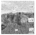
- test material No. A TEM image photograph of No. 1 is shown in FIG.
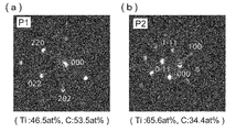
- FIGS. 3A and 3B show electron diffraction image photographs at the points P1 and P2 in FIG. 2 together with atomic coordinates, together with atomic composition ratios.
- the test material No. 4 a TEM image photograph is shown in FIG. 4
- electron diffraction image photographs and atomic composition ratios at points P4 to P12 in FIG. 4 are shown in FIGS. 5 (a) to 5 (i), respectively.
- the contact resistance of the test material was measured using a contact resistance measuring device shown in FIG.
- the test material is sandwiched between two carbon cloths from both sides, and the outside is pressurized to a load of 98 N (10 kgf) with a copper electrode with a contact area of 1 cm 2 , and a current of 7.4 mA is applied using a DC current power source.
- the resistance value was calculated by measuring the voltage applied between the carbon cloths with a voltmeter.
- the obtained resistance values are shown in Table 1 as the initial contact resistance.
- the electrical conductivity acceptance criterion was a contact resistance of 10 m ⁇ ⁇ cm 2 or less.
- the adhesion of the carbon layer was evaluated using the contact resistance measuring device (see FIG. 6) used for measuring the contact resistance. Similar to the measurement of the contact resistance, the test material was sandwiched between two carbon cloths from both sides, and the outer side was pressurized to a load of 98 N (10 kgf) with a copper electrode having a contact area of 1 cm 2 and was pressed from both sides. While maintaining the state, the film was pulled out in the surface direction (pull-out test). After the pull-out test, the sliding region by the copper electrode on the surface of the test material was visually observed and evaluated by the remaining state of the carbon layer, that is, the degree of exposure of the base material.
- the acceptance criteria for adhesion is that the exposed area ratio of the base material is less than 50%, and that the base material is not exposed at all is "Excellent", the base material is exposed to less than 50% Table 1 shows “ ⁇ ” as good and “x” as bad when exposed at 50% or more.
- test material No. In Nos. 1 to 6 a layer in which granular substances containing Ti and C are gathered under the carbon layer (C simple substance) is observed.
- a layer having a thickness of about 50 nm was formed as shown in FIG. Under the layer containing Ti and C was Ti alone (Ti: 100 at% at point P3 in FIG. 2), and oxygen (O) was not detected.
- Test material No. From the atomic composition ratio and crystal structure (see FIG. 3), the granular materials of the layer containing 1 Ti and C are titanium carbide (Ti: 46.5 at%, C: 53.5 at%) and carbon solid solution titanium. It was confirmed that these were two types of products (Ti: 65.6 at%, C: 34.4 at%) (measured values at points P1 and P2 of test material No. 1).
- test material No. Test material No. 1 having a heat treatment temperature higher than 1 and a longer treatment time. As shown in FIG. 4, a layer having a thickness of about 100 nm containing Ti and C was formed. This layer is composed of granular titanium carbide (points P4 to P8 in FIG. 4) and granular carbon solid solution titanium (in FIG.
- test material No. Nos. 1 to 6 show that the passive film (TiO 2 ) of the base material disappears, and further, an intermediate layer having two kinds of products of granular titanium carbide and carbon solid solution titanium between the base material and the carbon layer.
- 1 is an example of a fuel cell separator according to the present invention in which is formed.
- test material No. In Nos. 1 to 6 since the passive film on the surface of the substrate disappeared, the initial contact resistance was good as shown in Table 1. Furthermore, since the intermediate layer was formed, the adhesion between the base material and the carbon layer was excellent, and no exposure of the base material was observed in the sliding region after the pull-out test (base material exposed area ratio: 0%). . In addition, since the increase in contact resistance after the corrosion resistance test was extremely small and excellent in durability, it can be inferred that almost no passive film was formed on the surface of the base material in the corrosion resistance test. It was confirmed that the corrosive environment (sulfuric acid aqueous solution) did not enter between the material and the carbon layer.
- test material No. In Nos. 7 to 9 film-like titanium oxide was detected between the carbon layer and the layer composed of Ti alone, and it was confirmed that a passive film was present on the surface of the base material. There was no area to be detected and no intermediate layer was formed.
- test material No. No. 7 because no heat treatment was performed after the carbon layer was formed, and a thick passive film (natural oxide film) of the base material was present at the interface with the carbon layer, so although the initial contact resistance met the acceptance criteria, It was inferior to the examples (test materials No. 1 to 6).
- Test material No. In Nos. 8 and 9 the heat treatment temperature was low, and the passive film was thinned by reacting with carbon to some extent. Improved from 7.
- test material No. 7 to 9 were inferior in durability, and the contact resistance greatly increased in the corrosion resistance test. This is because there was a gap at the interface between the base material and the carbon layer, and the sulfuric acid aqueous solution entered the gap from the end face of the test material in the corrosion resistance test and contacted a wide area of the base material surface (passive film). This is because the passive film has grown.
- the fuel cell separator of the present invention is useful for various fuel cells, particularly for fuel cell vehicles, home cogeneration systems, solid polymer fuel cells for portable devices such as mobile phones and personal computers.
Landscapes
- Chemical & Material Sciences (AREA)
- Life Sciences & Earth Sciences (AREA)
- Engineering & Computer Science (AREA)
- Manufacturing & Machinery (AREA)
- Sustainable Development (AREA)
- Sustainable Energy (AREA)
- Chemical Kinetics & Catalysis (AREA)
- Electrochemistry (AREA)
- General Chemical & Material Sciences (AREA)
- Composite Materials (AREA)
- Fuel Cell (AREA)
Abstract
Priority Applications (4)
| Application Number | Priority Date | Filing Date | Title |
|---|---|---|---|
| EP12747496.3A EP2677580A4 (fr) | 2011-02-14 | 2012-02-14 | Séparateur pour pile à combustible |
| CN201280008811.5A CN103380525B (zh) | 2011-02-14 | 2012-02-14 | 燃料电池隔板 |
| US13/982,411 US20130302719A1 (en) | 2011-02-14 | 2012-02-14 | Fuel cell separator |
| KR1020137021300A KR101548064B1 (ko) | 2011-02-14 | 2012-02-14 | 연료 전지 세퍼레이터 |
Applications Claiming Priority (4)
| Application Number | Priority Date | Filing Date | Title |
|---|---|---|---|
| JP2011028423 | 2011-02-14 | ||
| JP2011-028423 | 2011-02-14 | ||
| JP2012009653A JP5108976B2 (ja) | 2011-02-14 | 2012-01-20 | 燃料電池セパレータ |
| JP2012-009653 | 2012-01-20 |
Publications (1)
| Publication Number | Publication Date |
|---|---|
| WO2012111671A1 true WO2012111671A1 (fr) | 2012-08-23 |
Family
ID=46672589
Family Applications (1)
| Application Number | Title | Priority Date | Filing Date |
|---|---|---|---|
| PCT/JP2012/053409 WO2012111671A1 (fr) | 2011-02-14 | 2012-02-14 | Séparateur pour pile à combustible |
Country Status (6)
| Country | Link |
|---|---|
| US (1) | US20130302719A1 (fr) |
| EP (1) | EP2677580A4 (fr) |
| JP (1) | JP5108976B2 (fr) |
| KR (1) | KR101548064B1 (fr) |
| CN (1) | CN103380525B (fr) |
| WO (1) | WO2012111671A1 (fr) |
Cited By (1)
| Publication number | Priority date | Publication date | Assignee | Title |
|---|---|---|---|---|
| JP2015022885A (ja) * | 2013-07-18 | 2015-02-02 | トヨタ車体株式会社 | 燃料電池のセパレータ及び燃料電池のセパレータの製造方法 |
Families Citing this family (15)
| Publication number | Priority date | Publication date | Assignee | Title |
|---|---|---|---|---|
| JP6061702B2 (ja) * | 2013-01-30 | 2017-01-18 | 株式会社神戸製鋼所 | 燃料電池セパレータ用材料および燃料電池セパレータの製造方法 |
| JP6043262B2 (ja) * | 2013-09-26 | 2016-12-14 | 株式会社神戸製鋼所 | 燃料電池セパレータおよびその親水化処理方法 |
| KR20180067708A (ko) * | 2013-11-11 | 2018-06-20 | 가부시키가이샤 고베 세이코쇼 | 티타늄제 연료 전지 세퍼레이터재 및 티타늄제 연료 전지 세퍼레이터재의 제조 방법 |
| JP2016122642A (ja) * | 2014-05-28 | 2016-07-07 | 株式会社神戸製鋼所 | 燃料電池用セパレータ材及びその製造方法 |
| WO2015182246A1 (fr) * | 2014-05-29 | 2015-12-03 | 住友電気工業株式会社 | Procédé de fabrication de lingot de carbure de silicium, substrat germe en carbure de silicium et substrat en carbure de silicium |
| JP6160584B2 (ja) | 2014-09-19 | 2017-07-12 | トヨタ自動車株式会社 | 燃料電池用セパレータの製造方法 |
| JP6160877B2 (ja) * | 2015-04-13 | 2017-07-12 | トヨタ自動車株式会社 | 燃料電池用セパレータの製造方法及び燃料電池用セパレータ |
| EP3702491A4 (fr) * | 2017-10-24 | 2021-03-24 | Usui Co., Ltd. | Matériau métallique et son procédé de production |
| JP6856012B2 (ja) * | 2017-12-14 | 2021-04-07 | トヨタ自動車株式会社 | 燃料電池用のセパレータ |
| CN109860649B (zh) * | 2019-01-17 | 2022-02-08 | 上海大学 | 一种用于燃料电池的含渗碳层的隔板的制备方法 |
| JP7323929B2 (ja) * | 2019-12-11 | 2023-08-09 | 株式会社プラズマイオンアシスト | 燃料電池用セパレータ及び燃料電池用セパレータの製造方法 |
| CN111304478B (zh) * | 2020-02-24 | 2021-04-20 | 北京科技大学 | 一种制备高导热鳞片石墨/碳化铬/钛基复合材料的方法 |
| EP4010511A4 (fr) * | 2020-02-26 | 2022-11-09 | Treadstone Technologies, Inc. | Composant présentant une résistance de contact de surface améliorée et une activité de réaction améliorée et procédés pour sa fabrication |
| CN112670670B (zh) * | 2020-12-24 | 2022-12-06 | 远景动力技术(江苏)有限公司 | 锂离子电池用隔膜及快充型锂离子电池的制备方法 |
| JP7435484B2 (ja) * | 2021-01-12 | 2024-02-21 | トヨタ自動車株式会社 | 燃料電池用のセパレータ、及び、燃料電池スタック |
Citations (12)
| Publication number | Priority date | Publication date | Assignee | Title |
|---|---|---|---|---|
| JP2000012048A (ja) * | 1998-06-18 | 2000-01-14 | Toyota Motor Corp | 燃料電池用ガスセパレータと該燃料電池用セパレータを用いた燃料電池、並びに燃料電池用ガスセパレータの製造方法 |
| JP2000138067A (ja) * | 1998-05-07 | 2000-05-16 | Toyota Motor Corp | 燃料電池用ガスセパレ―タと該燃料電池用ガスセパレ―タを用いた燃料電池、並びに燃料電池用ガスセパレ―タの製造方法 |
| JP2001283872A (ja) * | 2000-03-30 | 2001-10-12 | Nisshin Steel Co Ltd | 低温型燃料電池用セパレータ及びその製造方法 |
| JP3904690B2 (ja) | 1997-10-14 | 2007-04-11 | 日新製鋼株式会社 | 低温型燃料電池用セパレータ |
| JP3904696B2 (ja) | 1997-11-11 | 2007-04-11 | 日新製鋼株式会社 | 低温型燃料電池用セパレータ及びその製造方法 |
| JP2007207718A (ja) | 2006-02-06 | 2007-08-16 | Tokai Univ | 燃料電池用セパレータおよびその製造方法 |
| JP2008204876A (ja) | 2007-02-22 | 2008-09-04 | Toyota Motor Corp | 燃料電池用セパレータ、燃料電池用セパレータの製造方法及び燃料電池 |
| JP4147925B2 (ja) | 2002-12-04 | 2008-09-10 | トヨタ自動車株式会社 | 燃料電池用セパレータ |
| JP2010248570A (ja) * | 2009-04-15 | 2010-11-04 | Toyota Motor Corp | チタン系材料及び燃料電池用セパレータ |
| JP2010248572A (ja) * | 2009-04-15 | 2010-11-04 | Toyota Motor Corp | チタン系材料、その製造方法及び燃料電池用セパレータ |
| WO2012011200A1 (fr) * | 2010-07-20 | 2012-01-26 | 株式会社神戸製鋼所 | Séparateur de pile à combustible au titane |
| WO2012011201A1 (fr) * | 2010-07-20 | 2012-01-26 | 株式会社神戸製鋼所 | Séparateur de pile à combustible au titane |
Family Cites Families (3)
| Publication number | Priority date | Publication date | Assignee | Title |
|---|---|---|---|---|
| US6761990B1 (en) * | 1999-01-21 | 2004-07-13 | Asahi Glass Company, Limited | Solid polymer electrolyte fuel cell |
| US7592037B2 (en) * | 2004-04-13 | 2009-09-22 | Nissan Motor Co., Ltd. | Fuel cell separator, fuel cell stack, fuel cell vehicle, and method of manufacturing the fuel cell separator |
| JP5088318B2 (ja) * | 2006-04-14 | 2012-12-05 | トヨタ自動車株式会社 | チタン製の部材に対して行う貴金属めっき |
-
2012
- 2012-01-20 JP JP2012009653A patent/JP5108976B2/ja not_active Expired - Fee Related
- 2012-02-14 US US13/982,411 patent/US20130302719A1/en not_active Abandoned
- 2012-02-14 EP EP12747496.3A patent/EP2677580A4/fr not_active Withdrawn
- 2012-02-14 CN CN201280008811.5A patent/CN103380525B/zh not_active Expired - Fee Related
- 2012-02-14 KR KR1020137021300A patent/KR101548064B1/ko active IP Right Grant
- 2012-02-14 WO PCT/JP2012/053409 patent/WO2012111671A1/fr active Application Filing
Patent Citations (12)
| Publication number | Priority date | Publication date | Assignee | Title |
|---|---|---|---|---|
| JP3904690B2 (ja) | 1997-10-14 | 2007-04-11 | 日新製鋼株式会社 | 低温型燃料電池用セパレータ |
| JP3904696B2 (ja) | 1997-11-11 | 2007-04-11 | 日新製鋼株式会社 | 低温型燃料電池用セパレータ及びその製造方法 |
| JP2000138067A (ja) * | 1998-05-07 | 2000-05-16 | Toyota Motor Corp | 燃料電池用ガスセパレ―タと該燃料電池用ガスセパレ―タを用いた燃料電池、並びに燃料電池用ガスセパレ―タの製造方法 |
| JP2000012048A (ja) * | 1998-06-18 | 2000-01-14 | Toyota Motor Corp | 燃料電池用ガスセパレータと該燃料電池用セパレータを用いた燃料電池、並びに燃料電池用ガスセパレータの製造方法 |
| JP2001283872A (ja) * | 2000-03-30 | 2001-10-12 | Nisshin Steel Co Ltd | 低温型燃料電池用セパレータ及びその製造方法 |
| JP4147925B2 (ja) | 2002-12-04 | 2008-09-10 | トヨタ自動車株式会社 | 燃料電池用セパレータ |
| JP2007207718A (ja) | 2006-02-06 | 2007-08-16 | Tokai Univ | 燃料電池用セパレータおよびその製造方法 |
| JP2008204876A (ja) | 2007-02-22 | 2008-09-04 | Toyota Motor Corp | 燃料電池用セパレータ、燃料電池用セパレータの製造方法及び燃料電池 |
| JP2010248570A (ja) * | 2009-04-15 | 2010-11-04 | Toyota Motor Corp | チタン系材料及び燃料電池用セパレータ |
| JP2010248572A (ja) * | 2009-04-15 | 2010-11-04 | Toyota Motor Corp | チタン系材料、その製造方法及び燃料電池用セパレータ |
| WO2012011200A1 (fr) * | 2010-07-20 | 2012-01-26 | 株式会社神戸製鋼所 | Séparateur de pile à combustible au titane |
| WO2012011201A1 (fr) * | 2010-07-20 | 2012-01-26 | 株式会社神戸製鋼所 | Séparateur de pile à combustible au titane |
Non-Patent Citations (1)
| Title |
|---|
| See also references of EP2677580A4 |
Cited By (2)
| Publication number | Priority date | Publication date | Assignee | Title |
|---|---|---|---|---|
| JP2015022885A (ja) * | 2013-07-18 | 2015-02-02 | トヨタ車体株式会社 | 燃料電池のセパレータ及び燃料電池のセパレータの製造方法 |
| US9780389B2 (en) | 2013-07-18 | 2017-10-03 | Toyota Shatai Kabushiki Kaisha | Fuel cell separator and production method for fuel cell separator |
Also Published As
| Publication number | Publication date |
|---|---|
| KR101548064B1 (ko) | 2015-08-27 |
| EP2677580A1 (fr) | 2013-12-25 |
| KR20130124540A (ko) | 2013-11-14 |
| JP2012186147A (ja) | 2012-09-27 |
| JP5108976B2 (ja) | 2012-12-26 |
| EP2677580A4 (fr) | 2014-07-30 |
| CN103380525A (zh) | 2013-10-30 |
| CN103380525B (zh) | 2016-04-06 |
| US20130302719A1 (en) | 2013-11-14 |
Similar Documents
| Publication | Publication Date | Title |
|---|---|---|
| JP5108976B2 (ja) | 燃料電池セパレータ | |
| JP6122589B2 (ja) | 燃料電池セパレータ | |
| JP5753830B2 (ja) | 燃料電池セパレータおよびその製造方法 | |
| JP4886885B2 (ja) | チタン製燃料電池セパレータ | |
| JP5342462B2 (ja) | 燃料電池セパレータの製造方法 | |
| JP4886884B2 (ja) | チタン製燃料電池セパレータおよびその製造方法 | |
| JP5342518B2 (ja) | チタン製燃料電池セパレータの製造方法 | |
| JP5968857B2 (ja) | チタン製燃料電池セパレータの製造方法 | |
| JP5507496B2 (ja) | 燃料電池セパレータの製造方法 | |
| JP2010182593A (ja) | 燃料電池セパレータ用耐食皮膜および燃料電池セパレータ | |
| JP6414369B1 (ja) | 燃料電池のセパレータ用鋼板の基材ステンレス鋼板およびその製造方法 | |
| JP5108986B2 (ja) | 燃料電池セパレータ | |
| JP6043262B2 (ja) | 燃料電池セパレータおよびその親水化処理方法 | |
| JP6344539B1 (ja) | チタン材、セル用構成部材、セル、および固体高分子形燃料電池 | |
| JP5575696B2 (ja) | 燃料電池セパレータの製造方法 | |
| JP2017061731A (ja) | チタン製基材、チタン材、および固体高分子形燃料電池用セル部材 | |
| JP2016171077A (ja) | 固体酸化物形燃料電池用金属部材およびその製造方法 | |
| JP2012212644A (ja) | 燃料電池セパレータの製造方法 |
Legal Events
| Date | Code | Title | Description |
|---|---|---|---|
| WWE | Wipo information: entry into national phase |
Ref document number: 201280008811.5 Country of ref document: CN |
|
| 121 | Ep: the epo has been informed by wipo that ep was designated in this application |
Ref document number: 12747496 Country of ref document: EP Kind code of ref document: A1 |
|
| WWE | Wipo information: entry into national phase |
Ref document number: 13982411 Country of ref document: US |
|
| WWE | Wipo information: entry into national phase |
Ref document number: 2012747496 Country of ref document: EP |
|
| ENP | Entry into the national phase |
Ref document number: 20137021300 Country of ref document: KR Kind code of ref document: A |
|
| NENP | Non-entry into the national phase |
Ref country code: DE |