WO2012108430A1 - ファインダ装置及びカメラ、並びにそれらの調整方法 - Google Patents
ファインダ装置及びカメラ、並びにそれらの調整方法 Download PDFInfo
- Publication number
- WO2012108430A1 WO2012108430A1 PCT/JP2012/052744 JP2012052744W WO2012108430A1 WO 2012108430 A1 WO2012108430 A1 WO 2012108430A1 JP 2012052744 W JP2012052744 W JP 2012052744W WO 2012108430 A1 WO2012108430 A1 WO 2012108430A1
- Authority
- WO
- WIPO (PCT)
- Prior art keywords
- image
- optical system
- optical
- display unit
- subject
- Prior art date
- Legal status (The legal status is an assumption and is not a legal conclusion. Google has not performed a legal analysis and makes no representation as to the accuracy of the status listed.)
- Ceased
Links
Images


Classifications
-
- G—PHYSICS
- G03—PHOTOGRAPHY; CINEMATOGRAPHY; ANALOGOUS TECHNIQUES USING WAVES OTHER THAN OPTICAL WAVES; ELECTROGRAPHY; HOLOGRAPHY
- G03B—APPARATUS OR ARRANGEMENTS FOR TAKING PHOTOGRAPHS OR FOR PROJECTING OR VIEWING THEM; APPARATUS OR ARRANGEMENTS EMPLOYING ANALOGOUS TECHNIQUES USING WAVES OTHER THAN OPTICAL WAVES; ACCESSORIES THEREFOR
- G03B13/00—Viewfinders; Focusing aids for cameras; Means for focusing for cameras; Autofocus systems for cameras
- G03B13/02—Viewfinders
- G03B13/06—Viewfinders with lenses with or without reflectors
Definitions
- the present invention relates to a finder device, a camera equipped with a finder device, and an adjustment method thereof.
- an optical view finder for optically observing a subject and an image obtained by imaging the subject are displayed on a liquid crystal display (LCD: Liquid).
- LCD liquid crystal display
- EMF Electric View Finder
- OVF and EVF are switched, and one image is selectively observed.
- an EVF image is superimposed on an OVF optical image and observed. Accordingly, the photographer can instantly confirm the captured image by EVF without taking his eyes off the viewfinder.
- the subject appearing in the observed image may be displaced.
- an optical image by OVF and an image by EVF are superimposed and observed, there may be a deviation between subjects appearing in both images regardless of the movement of the subject. Such a deviation of the subject may give the photographer a sense of incongruity and may reduce visibility.
- the deviation of the captured image subject relative to the optical image subject can be eliminated by correcting the image signal input to the LCD, but a display panel having a size sufficiently larger than the size of the captured image to be displayed is required. Become.
- horizontal and vertical lines such as frame lines will be inclined with respect to the horizontal and vertical dot rows on the display panel.
- the dots are conspicuous, and there is a risk that the photographer may feel uncomfortable.
- the present invention has been made in view of the above-described circumstances, and an object of the present invention is to provide a finder device and a camera that can reduce a sense of discomfort given to a photographer and improve visibility.
- a first optical system for optically observing a subject a display unit capable of displaying an image corresponding to an optical image observed by the first optical system, and the display unit And a second optical system that guides an image to the optical path of the first optical system, and the finder device that is visually recognized in a state where the subject appearing in the optical image and the subject appearing in the image are superimposed and matched.
- a camera that can be displayed.
- the uncomfortable feeling given to the photographer can be reduced and the visibility can be improved.
- the figure which shows the fixing structure of the display part of the finder apparatus of FIG. The figure for demonstrating the adjustment method of the camera of FIG.
- FIG. 1 shows an example of a viewfinder device and a camera for explaining an embodiment of the present invention.
- the camera 1 includes an imaging unit 2, a viewfinder device 3, an operation unit 4, and a control unit 5.
- the imaging unit 2 processes the image data by processing the CCD image sensor 10, the imaging optical system 11 that forms an optical image of the subject on the light receiving surface of the CCD image sensor 10, and the signal output from the CCD image sensor 10.
- a signal processing circuit 12 to be generated and an image memory 13 for storing image data generated by the signal processing circuit 12 are configured.
- the finder device 3 includes a first optical system 20 for optically observing a subject, an LCD 21, a second optical system 22 that guides an image displayed on the LCD 21 to the optical path of the first optical system 20, It consists of
- the first optical system 20 includes an objective lens 30, a diopter adjusting lens 31 for adjusting the diopter of the finder, and an eyepiece 32.
- the field-of-view range of the first optical system 20 is a range substantially equal to the field-of-view range of the imaging optical system 11 of the imaging unit 2.
- the second optical system 22 includes a target lens 33 for focusing on the LCD 21 and a cube-shaped half mirror 34 for guiding an image displayed on the LCD 21 to the optical path of the first optical system 20.
- the OVF is configured by the first optical system 20
- the EVF is configured by the LCD 21 and the second optical system 22, the diopter adjustment lens 31, and the eyepiece lens 32.
- the operation unit 4 instructs the operation of the camera 1 and performs various settings.
- the operation unit 4 instructs the imaging unit 2 to perform imaging or switches between OVF and EVF in the finder device 3. A combination setting is made.
- the control unit 5 drives each unit of the camera 1 in response to an operation on the operation unit 4 and changes the setting.
- FIG. 2 is an exploded view of the finder device 3, and FIG. 3 shows the first optical system 20 and the second optical system 22.
- the finder device 3 has a case 40 in which the first optical system 20, the LCD 21, and the second optical system 22 are assembled.
- the objective lens 30, the diopter adjustment lens 31, and the eyepiece lens 32 constituting the first optical system 20 are held in the case 40 in a state where their optical axes are aligned with each other.
- the optical axis X of the first optical system 20 is disposed along the x-axis direction.
- the case 40 is provided with a pair of guide shafts 41 extending in parallel with the optical axis of the first optical system 20.
- the diopter adjustment lens 31 is supported by a pair of guide shafts 41, and moves back and forth along the pair of guide shafts 41 in conjunction with the rotation operation of the diopter adjustment dial 71 provided on one side surface of the case 40. Moved. Thereby, the diopter of the finder is adjusted.
- the half mirror 34 constituting the second optical system 22 is disposed between the objective lens 30 and the diopter adjustment lens 31 and is held by the case 40.
- the target lens 33 which comprises the 2nd optical system 22 is the direction (In the example of illustration, the optical axis of the 1st optical system 20 extended in a x direction) which cross
- the optical axis Y of the second optical system 22 intersects the optical axis X of the first optical system 20 in the half mirror 34.
- the LCD 21 is disposed on an extension of the optical axis Y of the second optical system 22, and the case 40 is provided with a support portion 42 that supports the LCD 21.
- the support portion 42 has a reference surface orthogonal to the optical axis Y, and the LCD 21 is supported by the support portion 42 so that the position and orientation relative to the optical axis Y can be adjusted on the reference surface.
- the A holding member 43 is attached to the support portion 42, and the LCD 21 is held between the reference surface of the support portion 42 and the holding member 43.
- the light incident on the objective lens 30 travels along the optical axis X of the first optical system 20, passes through the half mirror 34 and the diopter adjustment lens 31, and is emitted from the eyepiece lens 32.
- the light emitted from the display panel 23 of the LCD 21 travels along the optical axis Y of the second optical system 22, passes through the target lens 33 and enters the half mirror 34.
- the light is reflected in the direction along the optical axis X of the optical system 20 and guided into the optical path of the first optical system 20.
- the light passes through the diopter adjustment lens 31 and is emitted from the eyepiece lens 32.
- the viewfinder device 3 further includes a light shielding plate 50 for blocking the incidence of light on the objective lens 30 and a drive mechanism for moving the light shielding plate 50 so that the objective lens 30 is exposed and concealed. .
- the front wall 46 of the case 40 holding the objective lens 30 is provided with a pair of guides 47 extending in a predetermined direction (z direction in the illustrated example).
- the guide 47 is disposed on the front wall portion 46 and is supported so as to be movable back and forth along the guide 47.
- a holding plate 56 is attached to the front wall portion 46, and the light shielding plate 50 is held between the holding plate 56 and the front wall portion 46.
- the drive mechanism is composed of a lever 51 and a motor 52 for rotating the lever 51.
- the lever 51 has a rotation shaft 53 connected to the motor 52 and an engagement pin 54 provided at a position separated from the rotation shaft 53.
- the light shielding plate 50 is formed with a long hole 55 extending in a direction intersecting the moving direction (y direction in the illustrated example), and the engaging pin 54 of the lever 51 is long in the long hole 55.
- the long hole 55 is engaged so as to be movable in the extending direction of the hole 55.
- the light shielding plate 50 In a state where the engagement pin 54 of the lever 51 is located below the rotation shaft 53 and at one end of the long hole 55 of the light shielding plate 50, the light shielding plate 50 is located on the lower side in the moving range. The objective lens 30 is completely exposed (FIG. 4C).
- the raising / lowering operation of the light shielding plate 50 is controlled by the control unit 5.
- the control unit 5 drives the motor 52 when the operation unit 4 selects the mode for observing only the OVF optical image or the mode for observing the OVF optical image and the EVF image superimposed.
- the light shielding plate 50 is lowered.
- the objective lens 30 is exposed and light enters the first optical system 20, and an optical image can be observed.
- the control unit 5 drives the motor 52 to raise the light shielding plate 50.
- the objective lens 30 is concealed so that the light incident on the first optical system 20 is blocked, and only the display image can be observed.
- the support portion 42 of the case 40 that supports the LCD 21 has a bottom portion 48 on which a reference surface 48A orthogonal to the optical axis Y is formed, and a peripheral wall portion 49 that surrounds the LCD 21.
- a window 48B having an opening larger than the display panel 23 of the LCD 21 is formed in a region of the bottom 48 where the optical axes Y intersect.
- the LCD 21 overlaps the opening of the window 48B with the display panel 23 overlapped with the opening of the window 48B. It is arranged on the reference plane 48A.
- a gap g is placed between the outer periphery of the LCD 21 and the inner periphery of the peripheral wall portion 49. Due to the gap g, the position and posture of the LCD 21 with respect to the optical axis Y (rotation around the optical axis Y) can be adjusted on the reference plane 48A.
- the holding member 43 for holding the LCD 21 is extended from the frame portion 44 toward the inside of the frame.
- the frame portion 44 is overlapped with the edge of the peripheral wall portion 49 of the support portion 42 on the opening side (the side opposite to the bottom portion 48).
- a tongue-shaped pressing portion 45 is formed of, for example, a metal plate such as stainless steel, and the pressing portion 45 can be bent elastically.
- the pressing portion 45 is disposed so as to overlap the LCD 21 and presses the LCD 21 toward the reference surface 48A of the support portion 42. Thereby, the LCD 21 is held between the reference surface 48A and the pressing portion 45. The LCD 21 that is sandwiched and held between the reference surface 48A and the pressing portion 45 is temporarily fixed.
- the position and posture of the LCD 21 with respect to the optical axis Y are adjusted in the temporarily fixed state.
- the pressing portion 45 of the holding member 43 and the LCD 21, and the frame portion 44 of the holding member 43 and the peripheral wall portion 49 of the support portion 42 are bonded together by the adhesive 70. Thereby, the LCD 21 is fixed to the support portion 42.
- the surface of the holding member 43 that faces the pressing portion 45 is covered with the cover member 24.
- the cover member 24 is detachably attached to the LCD 21 and is integrated with the LCD 21.
- An adhesive layer 25 formed of, for example, a double-sided adhesive tape is provided on the surface of the cover member 24.
- the pressing portion 45 contacts the adhesive layer 25 of the cover member 24 and is adhered to the adhesive layer 25 of the cover member 24.
- the LCD 21 can be easily separated by removing the cover member 24. Can be prevented, and the LCD 21 can be reused.
- the adjustment of the finder device 3 is to adjust the position and posture of the LCD 21 with respect to the optical axis Y of the second optical system 22, and the subject 80 for alignment is imaged, and the subject 80 is observed by the finder device 3. Done.
- a chart having a cross mark drawn on the surface thereof is used as the subject 80, but the present invention is not limited to this, and it is possible to define two reference points that are separated on the image plane. That's fine.
- the subject 80 is imaged by the imaging unit 2, and captured image data of the subject 80 is generated.
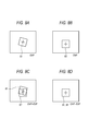
- the generated captured image data is displayed on the LCD 21, the displayed captured image is observed by the EVF (LCD 21, target lens 33, half mirror 34, diopter adjustment lens 31, and eyepiece lens 32) (IFG .8A).
- the subject 80 is observed by the OVF (objective lens 30, diopter adjustment lens 31, eyepiece 32) while maintaining the positional relationship between the camera 1 and the subject 80 at the time of imaging (FIG. 8B).
- OVF objective lens 30, diopter adjustment lens 31, eyepiece 32
- the captured image data of the subject 80 is displayed on the LCD 21, and the captured image is superimposed on the optical image observed by the OVF. If the position and posture of the LCD 21 with respect to the optical axis Y of the second optical system 22 are inappropriate, a deviation occurs between the subject 82 appearing in the optical image observed by the OVF and the subject 81 appearing in the captured image (FIG. .8C).
- the finder device 3 adjusted in this way it is possible to prevent the deviation of the subject appearing in the observed image when switching between OVF and EVF. Thereby, the uncomfortable feeling given to the photographer can be reduced and the visibility can be improved. Furthermore, the viewfinder device 3 adjusted in the camera 1 can also prevent the subject from being displaced due to the parallax between the imaging unit 2 and the viewfinder device 3.
- the adjustment method of the finder device 3 in the camera 1 has been described above.
- a finder device is prepared in advance. The adjustment is possible even with three single units.
- the subject 80 is imaged by the imaging unit 2 of the camera 1 and the captured image data of the subject 80 is prepared in advance. Then, the positional relationship between the finder device 3 of the camera 1 and the subject 80 at the time of imaging is reproduced by the finder device 3 alone, and the subject 80 is observed by OVF. Then, the captured image data of the subject 80 prepared in advance is displayed on the LCD 21, and the captured image is superimposed on the optical image observed by the OVF. Then, the position and orientation of the LCD 21 with respect to the optical axis Y (rotation around the optical axis Y) are adjusted on the reference surface 48A of the support portion 42 that supports the LCD 21, and the captured image is displayed on the subject 82 that appears in the optical image. The subject 81 that appears is matched.
- finder devices (1) to (5) are disclosed in this specification.
- a first optical system for optically observing a subject a display unit capable of displaying an image corresponding to an optical image observed by the first optical system, and the display unit And a second optical system that guides an image to the optical path of the first optical system, and the finder device that is visually recognized in a state where the subject appearing in the optical image and the subject appearing in the image are superimposed and matched.
- the finder device according to (1) further including a support unit that supports the display unit, wherein the support unit has a reference plane that intersects an optical axis of the second optical system, A finder device that supports the position and orientation of the display unit with respect to the optical axis of the second optical system so as to be adjustable on a reference surface.
- the finder device further including a holding member that is attached to the support portion and holds the display portion supported by the support portion, and the holding member includes the display portion described above.
- the display unit includes a detachable cover member on a side where the pressing unit contacts, and an adhesive layer is provided on a surface of the cover member.
- Finder device (5) The finder device according to (3) or (4), wherein the holding member and the cover member are bonded and fixed.
- the present specification further includes any one of the above finder devices (1) to (5), and an imaging unit that captures an image in a range substantially equal to the field of view of the first optical system,
- the display unit a camera capable of displaying an image captured by the imaging unit is disclosed.
- the present specification also provides a method for adjusting the finder device according to (1) above, in which an object is observed by the first optical system and corresponds to an optical image observed by the first optical system.
- the image is displayed on a display unit, the image is superimposed on the optical image, and the subject that appears in the image overlaps and coincides with the subject that appears in the optical image.
- a method for adjusting the finder device is disclosed in which the position and orientation of the display unit are adjusted and the adjusted display unit is fixed to the finder device.
- a camera adjustment method as described above, in which a subject is imaged by the imaging unit, and the subject is detected based on a positional relationship between the camera and the subject at the time of imaging. While observing with an optical system, an image obtained by imaging is displayed on the display unit, the image is superimposed on an optical image observed by the first optical system, and the subject appearing in the image is Adjustment of the camera for adjusting the position and orientation of the display unit with respect to the optical axis of the second optical system so as to overlap and match the subject appearing in the optical image, and fixing the adjusted display unit to the viewfinder device A method is disclosed.
- the uncomfortable feeling given to the photographer can be reduced and the visibility can be improved.
Landscapes
- Physics & Mathematics (AREA)
- General Physics & Mathematics (AREA)
- Viewfinders (AREA)
- Studio Devices (AREA)
Abstract
撮影者に与える違和感を軽減し、視認性を高めることのできるファインダ装置及びカメラを提供する。 ファインダ装置3は、被写体を光学的に観察するための第1の光学系20と、前記第1の光学系20によって観察される光学像に対応する画像を表示可能な表示部21と、前記表示部に表示された画像を前記第1の光学系の光路に導く第2の光学系22と、を備え、前記光学像にあらわれる前記被写体と、前記画像にあらわれる前記被写体と、が重畳一致した状態に視認される。
Description
本発明は、ファインダ装置及びファインダ装置を備えたカメラ、並びにそれらの調整方法に関する。
デジタルスチルカメラやデジタルビデオカメラなどのカメラのファインダ装置として、被写体を光学的に観察する光学ビューファインダ(OVF:Optical View Finder)と、被写体を撮像して得られた画像を液晶ディスプレイ(LCD:Liquid Crystal Display)に表示して、これを観察する電子ビューファインダ(EVF:Electric View Finder)とを備えたファインダ装置が知られている(例えば、特許文献1参照)。
上記のファインダ装置においては、例えば、OVFとEVFとが切り換えられ、一方の像が選択的に観察される。また、OVFによる光学像にEVFによる画像が重畳されて観察される場合もある。それにより、撮影者は、ファインダから目を離さずに、撮像画像をEVFによって瞬時に確認することができる。
LCDの位置決め誤差や、LCDにおける表示パネルの位置のバラツキなどに起因して、OVFによる光学像とEVFによる画像とが切り換えられる際に、観察される像にあらわれる被写体にずれが生じる場合がある。また、OVFによる光学像とEVFによる画像とが重畳されて観察される場合にも、被写体の移動に関わらず、双方の像にあらわれる被写体の間でずれが生じる場合がある。かかる被写体のずれは、撮影者に違和感を与え、また、視認性を低下させる虞がある。
光学像の被写体に対する撮像画像の被写体のずれは、LCDに入力される画像信号を補正することで解消することができるが、表示する撮像画像のサイズよりも十分に大きいサイズの表示パネルが必要となる。また、被写体のずれが回転を伴う場合に、これを画像信号補正によって解消しようとすると、枠線等の水平・垂直方向の線が、表示パネルの水平・垂直方向のドット列に対して傾くために、ドットが目立ってしまい、やはり撮影者に違和感を与える虞がある。
本発明は、上述した事情に鑑みなされたものであり、撮影者に与える違和感を軽減し、視認性を高めることのできるファインダ装置及びカメラを提供することを目的としている。
(1) 被写体を光学的に観察するための第1の光学系と、前記第1の光学系によって観察される光学像に対応する画像を表示可能な表示部と、前記表示部に表示された画像を前記第1の光学系の光路に導く第2の光学系と、を備え、前記光学像にあらわれる前記被写体と、前記画像にあらわれる前記被写体と、が重畳一致した状態に視認されるファインダ装置。
(2) 上記(1)のファインダ装置と、前記第1の光学系の視野とほぼ等しい範囲の画像を撮像する撮像部と、を備え、前記表示部は、前記撮像部によって撮像された画像を表示可能であるカメラ。
(2) 上記(1)のファインダ装置と、前記第1の光学系の視野とほぼ等しい範囲の画像を撮像する撮像部と、を備え、前記表示部は、前記撮像部によって撮像された画像を表示可能であるカメラ。
本発明によれば、撮影者に与える違和感を軽減し、視認性を高めることができる。
図1は、本発明の実施形態を説明するための、ファインダ装置及びカメラの一例を示す。
カメラ1は、撮像部2と、ファインダ装置3と、操作部4と、制御部5と、を備えている。
撮像部2は、CCDイメージセンサ10と、このCCDイメージセンサ10の受光面に被写体の光学像を結像させる撮像光学系11と、CCDイメージセンサ10から出力される信号を処理して画像データを生成する信号処理回路12と、信号処理回路12によって生成された画像データを記憶する画像メモリ13とで構成されている。
ファインダ装置3は、被写体を光学的に観察するための第1の光学系20と、LCD21と、LCD21に表示された画像を第1の光学系20の光路に導く第2の光学系22と、で構成されている。
第1の光学系20は、対物レンズ30と、ファインダの視度を調整するための視度調整レンズ31と、接眼レンズ32とで構成されている。第1の光学系20の視野範囲は、撮像部2の撮像光学系11の視野範囲とほぼ等しい範囲とされている。また、第2の光学系22は、LCD21に焦点を合わせるためのターゲットレンズ33と、LCD21に表示された画像を第1の光学系20の光路に導くためのキューブ型のハーフミラー34とで構成されている。第1の光学系20によりOVFが構成され、また、LCD21及び第2の光学系22、並びに視度調整レンズ31及び接眼レンズ32によりEVFが構成されている。
操作部4は、カメラ1の動作を指示し、また、各種の設定を行うためのものであって、例えば、撮像部2による撮像の指示や、ファインダ装置3におけるOVFとEVFとの切り替え若しく併用の設定がなされる。
制御部5は、操作部4における操作に応答して、カメラ1の各部を駆動し、設定を変更する。
図2は、ファインダ装置3を分解して示し、図3は、第1の光学系20及び第2の光学系22を示す。
ファインダ装置3は、第1の光学系20、LCD21、及び第2の光学系22が組み付けられるケース40を有している。
第1の光学系20を構成する対物レンズ30、視度調整レンズ31、及び接眼レンズ32は、それらの光軸を互いに一致させた状態にケース40に保持されている。図示の例において、第1の光学系20の光軸Xはx軸方向に沿って配置される。
ケース40には、第1の光学系20の光軸と平行に延在する一対のガイド軸41が設けられている。視度調整レンズ31は、一対のガイド軸41に支持されており、ケース40の一方の側面部に設けられる視度調整ダイヤル71の回転操作に連動して、一対のガイド軸41に沿って前後移動される。それにより、ファインダの視度が調整される。
第2の光学系22を構成するハーフミラー34は、対物レンズ30と視度調整レンズ31との間に配置されて、ケース40に保持されている。そして、第2の光学系22を構成するターゲットレンズ33は、第1の光学系20の光軸Xと交差する方向(図示の例においては、x方向に延びる第1の光学系20の光軸Xに直交するy方向)からハーフミラー34を臨む位置に配置されて、ケース40に保持されている。第2の光学系22の光軸Yは、ハーフミラー34において第1の光学系20の光軸Xに交差する。
LCD21は、第2の光学系22の光軸Yの延長上に配置され、ケース40には、LCD21を支持する支持部42が設けられている。詳細は後述するが、支持部42は、光軸Yと直交する基準面を有しており、LCD21は、この基準面上において光軸Yに対する位置及び姿勢を調整可能に支持部42に支持される。そして、支持部42には保持部材43が取付けられ、LCD21は、支持部42の基準面と保持部材43とによって挟まれて保持されている。
対物レンズ30に入射した光は、第1の光学系20の光軸Xに沿って進み、ハーフミラー34及び視度調整レンズ31を透過して、接眼レンズ32から出射される。また、LCD21の表示パネル23から出射された光は、第2の光学系22の光軸Yに沿って進み、ターゲットレンズ33を透過してハーフミラー34に入射し、ハーフミラー34によって第1の光学系20の光軸Xに沿う方向に反射されて第1の光学系20の光路内に導かれる。そして、視度調整レンズ31を透過して、接眼レンズ32から出射される。以上により、OVFによる光学像、及びEVFによる画像が、接眼レンズ32を覗く撮影者によって観察される。
ファインダ装置3は、対物レンズ30への光の入射を遮るための遮光板50と、対物レンズ30を露呈させ、また隠蔽するように遮光板50を移動させる駆動機構と、を更に有している。
対物レンズ30を保持しているケース40の前壁部46には、所定の方向(図示の例ではz方向)に延在する一対のガイド47が設けられており、遮光板50は、これら一対のガイド47の間で前壁部46上に配置され、ガイド47に沿って前後移動可能に支持されている。前壁部46には保持板56が取り付けられ、遮光板50は、この保持板56と前壁部46との間に挟まれて保持される。
駆動機構は、レバー51と、レバー51を回動させるためのモータ52とで構成されている。レバー51は、モータ52に連結された回動軸53と、回動軸53から離間した位置に設けられた係合ピン54とを有している。遮光板50には、その移動方向と交差する方向(図示の例においてはy方向)に延在する長孔55が形成されており、レバー51の係合ピン54は、長孔55内において長孔55の延在方向に移動可能に、長孔55に係合している。
図4を参照して、駆動機構及び遮光板50の動作について説明する。
レバー51の係合ピン54が、回動軸53よりも上に位置し、かつ、遮光板50の長孔55の一端(図示の例においては左端)に位置している状態で、遮光板50は、その移動範囲における上側に位置しており、対物レンズ30は、遮光板50によって隠蔽されている(FIG.4A)。
モータ52が駆動されてレバー51が回動するのに伴って、レバー51の係合ピン54は、回動軸53を中心とする円弧軌道C上を移動する。その際、係合ピン54は、長孔55内をその延在方向にスライド移動しながら降下し、これに係合する遮光板50もまた降下する(FIG.4B)。
レバー51の係合ピン54が、回動軸53よりも下に位置し、かつ、遮光板50の長孔55の一端に位置している状態で、遮光板50は、その移動範囲における下側に位置しており、対物レンズ30は、完全に露呈している(FIG.4C)。
以上の遮光板50の昇降動作は、制御部5によって制御される。例えば、操作部4においてOVFによる光学像のみを観察するモード、あるいはOVFによる光学像とEVFによる画像とを重畳させて観察するモードが選択された場合に、制御部5は、モータ52を駆動して遮光板50を降下させる。それにより、対物レンズ30が露呈して第1の光学系20に光が入射し、光学像が観察可能となる。また、EVFによる表示画像のみを観察するモードが選択された場合に、制御部5は、モータ52を駆動して遮光板50を上昇させる。それにより、対物レンズ30が隠蔽されて第1の光学系20への光の入射が遮られ、表示画像のみが観察可能となる。
次に、図5及び図6を参照して、LCD21の固定構造について説明する。
LCD21を支持するケース40の支持部42は、光軸Yと直交する基準面48Aが形成された底部48と、LCD21を取り囲む周壁部49とを有している。
光軸Yが交わる底部48の領域には、LCD21の表示パネル23よりも大きい開口を有する窓部48Bが形成されており、LCD21は、表示パネル23を窓部48Bの開口に重ねて底部48の基準面48A上に配置されている。この状態で、LCD21の外周と、周壁部49の内周との間には隙間gが置かれる。この隙間gがあることによって、基準面48A上において光軸Yに対するLCD21の位置及び姿勢(光軸Yまわりの回転)が調整可能となっている。
LCD21を保持する保持部材43は、支持部42の周壁部49の開口側(底部48とは反対側)の縁部に重ねられる枠部44と、枠部44から枠内に向けて延設された舌片状の押圧部45とを有している。保持部材43は、例えばステンレスなどの金属板で形成されており、押圧部45は、弾性的に湾曲可能である。
押圧部45は、LCD21に重なって配置され、LCD21を支持部42の基準面48Aに向けて押圧する。それにより、LCD21は、基準面48Aと押圧部45との間に挟まれて保持される。基準面48Aと押圧部45との間に挟まれて保持されるLCD21は、仮止めされた状態におかれる。
LCD21は、詳細は後述するが、上記の仮止めされた状態において、光軸Yに対する位置及び姿勢を調整される。LCD21の位置及び姿勢の調整が済んだ後、保持部材43の押圧部45とLCD21、及び保持部材43の枠部44と支持部42の周壁部49とが接着剤70によって接着される。それにより、LCD21は支持部42に固定される。
ここで、LCD21は、保持部材43の押圧部45に対向する面をカバー部材24によって覆われている。このカバー部材24は、LCD21に着脱可能に取り付けられ、LCD21と一体とされている。そして、このカバー部材24の表面には、例えば両面粘着テープ等によって形成される粘着層25が設けられている。押圧部45は、カバー部材24の粘着層25に接触し、また、カバー部材24の粘着層25に対して接着される。それにより、LCD21の調整が済んだ後であってLCD21が支持部42に固定される前に、例えば衝撃等が作用してLCD21が変位してしまうことを防止することができる。また、押圧部45が接着される粘着層25が設けられたカバー部材24は、LCD21に対して着脱可能であることから、カバー部材24を取り外すことによってLCD21を容易に分離することができ、LCD21の損壊を防止し、LCD21を再利用することができる。
次に、図7及び図8を参照して、ファインダ装置3の調整方法を説明する。
ファインダ装置3の調整は、第2の光学系22の光軸Yに対するLCD21の位置及び姿勢を調整するものであり、アライメント用の被写体80を撮像し、また、ファインダ装置3によって被写体80を観察して行われる。図示の例では、被写体80として、その表面に十字のマークが描かれたチャートが用いられているが、これに限られるものではなく、像平面において離間した2つの基準点を規定できるものであればよい。
まず、被写体80を、撮像部2によって撮像し、被写体80の撮像画像データを生成する。生成された撮像画像データがLCD21に表示されると、表示された撮像画像は、EVF(LCD21、ターゲットレンズ33、ハーフミラー34、視度調整レンズ31、及び接眼レンズ32)によって観察される(IFG.8A)。
上記の撮像時におけるカメラ1と被写体80との位置関係を保ったまま、被写体80をOVF(対物レンズ30、視度調整レンズ31、接眼レンズ32)によって観察する(FIG.8B)。
そして、被写体80の撮像画像データをLCD21に表示させ、OVFによって観察される光学像に撮像画像を重畳する。第2の光学系22の光軸Yに対するLCD21の位置及び姿勢が不適切であると、OVFによって観察される光学像にあらわれる被写体82と撮像画像にあらわれる被写体81との間にずれが生じる(FIG.8C)。
光学像の被写体82と撮像画像の被写体81との間にずれが生じている場合に、LCD21を支持する支持部42の基準面48A上において、光軸Yに対するLCD21の位置及び姿勢(光軸Yまわりの回転)を調整し、光学像の被写体82に対して撮像画像の被写体81を重畳一致させる(FIG.8D)。
このように調整されたファインダ装置3によれば、OVFとEVFとを切り換えた際に、観察される像にあらわれる被写体のずれを防止することができる。それにより、撮影者に与える違和感を軽減し、また、視認性を向上させることができる。更に、カメラ1において調整されたファインダ装置3は、撮像部2とファインダ装置3との視差に起因する被写体のずれも防止することができる。
以上、カメラ1におけるファインダ装置3の調整方法を説明したが、カメラ1の撮像部2によって被写体80を撮像して得られる撮像画像データと等価な画像データを予め用意しておくことによって、ファインダ装置3単体であっても、その調整は可能である。
具体的には、カメラ1の撮像部2によって被写体80を撮像して被写体80の撮像画像データを予め用意しておく。そして、上記の撮像時におけるカメラ1のファインダ装置3と被写体80との位置関係を、ファインダ装置3単体で再現し、被写体80をOVFによって観察する。そして、予め用意した被写体80の撮像画像データをLCD21に表示させ、OVFによって観察される光学像に撮像画像を重畳させる。そして、LCD21を支持する支持部42の基準面48A上において、光軸Yに対するLCD21の位置及び姿勢(光軸Yまわりの回転)を調整し、光学像にあらわれる被写体82に対して、撮像画像にあらわれる被写体81を一致させる。
以上、説明した通り、本明細書には、下記(1)~(5)のファインダ装置が開示されている。
(1) 被写体を光学的に観察するための第1の光学系と、前記第1の光学系によって観察される光学像に対応する画像を表示可能な表示部と、前記表示部に表示された画像を前記第1の光学系の光路に導く第2の光学系と、を備え、前記光学像にあらわれる前記被写体と、前記画像にあらわれる前記被写体と、が重畳一致した状態に視認されるファインダ装置。
(2) 上記(1)のファインダ装置であって、前記表示部を支持する支持部を更に備え、前記支持部は、前記第2の光学系の光軸と交差する基準面を有し、該基準面上において前記第2の光学系の光軸に対する前記表示部の位置及び姿勢を調整可能に支持するファインダ装置。
(3) 上記(2)のファインダ装置であって、前記支持部に取り付けられ、前記支持部に支持された前記表示部を保持する保持部材を更に備え、前記保持部材は、前記表示部を前記基準面に向けて弾性的に押圧する押圧部を有しているファインダ装置。
(4) 上記(3)に記載のファインダ装置であって、前記表示部は、前記押圧部が接触する側に着脱可能なカバー部材を有しており、前記カバー部材の表面に粘着層が設けられているファインダ装置。
(5) 上記(3)又は(4)のファインダ装置であって、前記保持部材と前記カバー部材とが接着固定されているファインダ装置。
(2) 上記(1)のファインダ装置であって、前記表示部を支持する支持部を更に備え、前記支持部は、前記第2の光学系の光軸と交差する基準面を有し、該基準面上において前記第2の光学系の光軸に対する前記表示部の位置及び姿勢を調整可能に支持するファインダ装置。
(3) 上記(2)のファインダ装置であって、前記支持部に取り付けられ、前記支持部に支持された前記表示部を保持する保持部材を更に備え、前記保持部材は、前記表示部を前記基準面に向けて弾性的に押圧する押圧部を有しているファインダ装置。
(4) 上記(3)に記載のファインダ装置であって、前記表示部は、前記押圧部が接触する側に着脱可能なカバー部材を有しており、前記カバー部材の表面に粘着層が設けられているファインダ装置。
(5) 上記(3)又は(4)のファインダ装置であって、前記保持部材と前記カバー部材とが接着固定されているファインダ装置。
また、本明細書には、上記(1)から(5)のいずれか一つのファインダ装置と、前記第1の光学系の視野とほぼ等しい範囲の画像を撮像する撮像部と、を備え、前記表示部は、前記撮像部によって撮像された画像を表示可能であるカメラが開示されている。
また、本明細書には、上記(1)のファインダ装置の調整方法であって、被写体を前記第1の光学系によって観察すると共に、前記第1の光学系によって観察される光学像に対応する画像を表示部に表示して前記光学像に前記画像を重畳させ、前記画像にあらわれる前記被写体が前記光学像にあらわれる前記被写体に重畳一致するように、前記第2の光学系の光軸に対する前記表示部の位置及び姿勢を調整し、調整された前記表示部を前記ファインダ装置に固定するファインダ装置の調整方法が開示されている。
また、本明細書には、上記のカメラの調整方法であって、被写体を前記撮像部によって撮像し、撮像時における前記カメラと前記被写体との位置関係のもとで前記被写体を前記第1の光学系によって観察すると共に、撮像して得られた画像を前記表示部に表示して、前記第1の光学系によって観察される光学像に前記画像を重畳させ、前記画像にあらわれる前記被写体が前記光学像にあらわれる前記被写体に重畳一致するように、前記第2の光学系の光軸に対する前記表示部の位置及び姿勢を調整し、調整された前記表示部を前記ファインダ装置に固定するカメラの調整方法が開示されている。
本発明によれば、撮影者に与える違和感を軽減し、視認性を高めることができる。
本発明を詳細にまた特定の実施態様を参照して説明したが、本発明の精神と範囲を逸脱することなく様々な変更や修正を加えることができることは当業者にとって明らかである。
本出願は、2011年02月08日出願の日本特許出願(特願2011-025506)に基づくものであり、その内容はここに参照として取り込まれる。
本出願は、2011年02月08日出願の日本特許出願(特願2011-025506)に基づくものであり、その内容はここに参照として取り込まれる。
1 カメラ
2 撮像部
3 ファインダ装置
4 操作部
5 制御部
20 第1の光学系
21 液晶ディスプレイ(表示部)
22 第2の光学系
24 カバー部材
25 粘着層
30 対物レンズ
31 視度調整レンズ
32 接眼レンズ
33 ターゲットレンズ
34 ハーフミラー
40 ケース
42 支持部
43 保持部材
45 押圧部
48 底部
48A 基準面
80 被写体
81 光学像にあらわれる被写体
82 表示画像にあらわれる被写体
2 撮像部
3 ファインダ装置
4 操作部
5 制御部
20 第1の光学系
21 液晶ディスプレイ(表示部)
22 第2の光学系
24 カバー部材
25 粘着層
30 対物レンズ
31 視度調整レンズ
32 接眼レンズ
33 ターゲットレンズ
34 ハーフミラー
40 ケース
42 支持部
43 保持部材
45 押圧部
48 底部
48A 基準面
80 被写体
81 光学像にあらわれる被写体
82 表示画像にあらわれる被写体
Claims (8)
- 被写体を光学的に観察するための第1の光学系と、
前記第1の光学系によって観察される光学像に対応する画像を表示可能な表示部と、
前記表示部に表示された画像を前記第1の光学系の光路に導く第2の光学系と、
を備え、
前記光学像にあらわれる前記被写体と、前記画像にあらわれる前記被写体と、が重畳一致した状態に視認されるファインダ装置。 - 請求項1に記載のファインダ装置であって、
前記表示部を支持する支持部を更に備え、
前記支持部は、前記第2の光学系の光軸と交差する基準面を有し、該基準面上において前記第2の光学系の光軸に対する前記表示部の位置及び姿勢を調整可能に支持するファインダ装置。 - 請求項2に記載のファインダ装置であって、
前記支持部に取り付けられ、前記支持部に支持された前記表示部を保持する保持部材を更に備え、
前記保持部材は、前記表示部を前記基準面に向けて弾性的に押圧する押圧部を有しているファインダ装置。 - 請求項3に記載のファインダ装置であって、
前記表示部は、前記押圧部が接触する側に着脱可能なカバー部材を有しており、
前記カバー部材の表面に粘着層が設けられているファインダ装置。 - 請求項3又は4に記載のファインダ装置であって、
前記保持部材と前記カバー部材とが接着固定されているファインダ装置。 - 請求項1から5のいずれか一項に記載のファインダ装置と、
前記第1の光学系の視野とほぼ等しい範囲の画像を撮像する撮像部と、
を備え、
前記表示部は、前記撮像部によって撮像された画像を表示可能であるカメラ。 - 請求項1に記載のファインダ装置の調整方法であって、
被写体を前記第1の光学系によって観察すると共に、前記第1の光学系によって観察される光学像に対応する画像を表示部に表示して前記光学像に前記画像を重畳させ、
前記画像にあらわれる前記被写体が前記光学像にあらわれる前記被写体に重畳一致するように、前記第2の光学系の光軸に対する前記表示部の位置及び姿勢を調整し、
調整された前記表示部を前記ファインダ装置に固定するファインダ装置の調整方法。 - 請求項6に記載のカメラの調整方法であって、
被写体を前記撮像部によって撮像し、
撮像時における前記カメラと前記被写体との位置関係のもとで前記被写体を前記第1の光学系によって観察すると共に、撮像して得られた画像を前記表示部に表示して、前記第1の光学系によって観察される光学像に前記画像を重畳させ、
前記画像にあらわれる前記被写体が前記光学像にあらわれる前記被写体に重畳一致するように、前記第2の光学系の光軸に対する前記表示部の位置及び姿勢を調整し、
調整された前記表示部を前記ファインダ装置に固定するカメラの調整方法。
Applications Claiming Priority (2)
| Application Number | Priority Date | Filing Date | Title |
|---|---|---|---|
| JP2011025506A JP2014077812A (ja) | 2011-02-08 | 2011-02-08 | ファインダ装置及びカメラ、並びにそれらの調整方法 |
| JP2011-025506 | 2011-02-08 |
Publications (1)
| Publication Number | Publication Date |
|---|---|
| WO2012108430A1 true WO2012108430A1 (ja) | 2012-08-16 |
Family
ID=46638643
Family Applications (1)
| Application Number | Title | Priority Date | Filing Date |
|---|---|---|---|
| PCT/JP2012/052744 Ceased WO2012108430A1 (ja) | 2011-02-08 | 2012-02-07 | ファインダ装置及びカメラ、並びにそれらの調整方法 |
Country Status (2)
| Country | Link |
|---|---|
| JP (1) | JP2014077812A (ja) |
| WO (1) | WO2012108430A1 (ja) |
Citations (9)
| Publication number | Priority date | Publication date | Assignee | Title |
|---|---|---|---|---|
| JPS5937777A (ja) * | 1982-08-25 | 1984-03-01 | Olympus Optical Co Ltd | 電子的撮像装置 |
| JPH03292067A (ja) * | 1989-12-28 | 1991-12-24 | Fuji Photo Film Co Ltd | ファインダ |
| JPH0430677A (ja) * | 1990-05-24 | 1992-02-03 | Fuji Photo Film Co Ltd | ハイブリッドファインダ |
| JPH06245114A (ja) * | 1993-02-16 | 1994-09-02 | Sony Corp | 電子スチルカメラの撮像状態表示方法およびその装置 |
| JPH0946559A (ja) * | 1995-07-26 | 1997-02-14 | Canon Inc | 複合カメラ |
| JP2000330158A (ja) * | 1999-05-18 | 2000-11-30 | Olympus Optical Co Ltd | ファインダー装置 |
| JP2001069377A (ja) * | 1999-08-27 | 2001-03-16 | Minolta Co Ltd | デジタルカメラ |
| JP2003078785A (ja) * | 2001-08-30 | 2003-03-14 | Olympus Optical Co Ltd | カメラのファインダ装置 |
| JP2006262504A (ja) * | 2006-04-17 | 2006-09-28 | Olympus Corp | 電子カメラ |
-
2011
- 2011-02-08 JP JP2011025506A patent/JP2014077812A/ja not_active Withdrawn
-
2012
- 2012-02-07 WO PCT/JP2012/052744 patent/WO2012108430A1/ja not_active Ceased
Patent Citations (9)
| Publication number | Priority date | Publication date | Assignee | Title |
|---|---|---|---|---|
| JPS5937777A (ja) * | 1982-08-25 | 1984-03-01 | Olympus Optical Co Ltd | 電子的撮像装置 |
| JPH03292067A (ja) * | 1989-12-28 | 1991-12-24 | Fuji Photo Film Co Ltd | ファインダ |
| JPH0430677A (ja) * | 1990-05-24 | 1992-02-03 | Fuji Photo Film Co Ltd | ハイブリッドファインダ |
| JPH06245114A (ja) * | 1993-02-16 | 1994-09-02 | Sony Corp | 電子スチルカメラの撮像状態表示方法およびその装置 |
| JPH0946559A (ja) * | 1995-07-26 | 1997-02-14 | Canon Inc | 複合カメラ |
| JP2000330158A (ja) * | 1999-05-18 | 2000-11-30 | Olympus Optical Co Ltd | ファインダー装置 |
| JP2001069377A (ja) * | 1999-08-27 | 2001-03-16 | Minolta Co Ltd | デジタルカメラ |
| JP2003078785A (ja) * | 2001-08-30 | 2003-03-14 | Olympus Optical Co Ltd | カメラのファインダ装置 |
| JP2006262504A (ja) * | 2006-04-17 | 2006-09-28 | Olympus Corp | 電子カメラ |
Also Published As
| Publication number | Publication date |
|---|---|
| JP2014077812A (ja) | 2014-05-01 |
Similar Documents
| Publication | Publication Date | Title |
|---|---|---|
| JP4829221B2 (ja) | ユーザの鏡像を表示することによってユーザを位置決めする装置、その位置決め方法、および画像捕捉装置 | |
| JP4965800B2 (ja) | 画像表示システム | |
| WO2017026144A1 (ja) | 撮像装置 | |
| EP4215979B1 (en) | Display apparatus, finder apparatus, and imaging apparatus | |
| CN104488256A (zh) | 照相机及其动作控制方法 | |
| WO2013118328A1 (ja) | 表示装置、電子機器及び表示装置用プログラム | |
| JP2007508593A (ja) | 特定の方向を向く撮像装置を備える視認装置 | |
| JP4994912B2 (ja) | 頭部装着型の映像表示装置 | |
| JP2007214964A (ja) | 映像表示装置 | |
| JP2025163307A (ja) | 撮像装置 | |
| WO2012108430A1 (ja) | ファインダ装置及びカメラ、並びにそれらの調整方法 | |
| JP7086618B2 (ja) | 撮像装置およびその制御方法 | |
| US8922697B2 (en) | Digital camera and finder device thereof | |
| JP5948232B2 (ja) | 撮像装置 | |
| JP2007079338A (ja) | フィルタ切替機構 | |
| EP1681854A2 (en) | Image pickup apparatus and display device | |
| JP3352209B2 (ja) | 撮像装置付き頭部装着型映像表示装置 | |
| JP2017120272A (ja) | 撮像装置 | |
| JP2003101825A (ja) | レンズ情報表示装置 | |
| JP4731448B2 (ja) | 観察装置および撮影装置 | |
| JP6036213B2 (ja) | アダプタ、及びカメラシステム | |
| JP2018063336A (ja) | 頭部装着型映像表示装置 | |
| JP2016143926A (ja) | 電子機器 | |
| JP5548011B2 (ja) | 撮像装置 | |
| JP2023178602A (ja) | 撮像装置 |
Legal Events
| Date | Code | Title | Description |
|---|---|---|---|
| 121 | Ep: the epo has been informed by wipo that ep was designated in this application |
Ref document number: 12745202 Country of ref document: EP Kind code of ref document: A1 |
|
| NENP | Non-entry into the national phase |
Ref country code: DE |
|
| 122 | Ep: pct application non-entry in european phase |
Ref document number: 12745202 Country of ref document: EP Kind code of ref document: A1 |
|
| NENP | Non-entry into the national phase |
Ref country code: JP |