WO2012108370A1 - Normal-type combine - Google Patents
Normal-type combine Download PDFInfo
- Publication number
- WO2012108370A1 WO2012108370A1 PCT/JP2012/052585 JP2012052585W WO2012108370A1 WO 2012108370 A1 WO2012108370 A1 WO 2012108370A1 JP 2012052585 W JP2012052585 W JP 2012052585W WO 2012108370 A1 WO2012108370 A1 WO 2012108370A1
- Authority
- WO
- WIPO (PCT)
- Prior art keywords
- threshing
- clutch
- lever
- threshing device
- traveling
- Prior art date
Links
Images


Classifications
-
- A—HUMAN NECESSITIES
- A01—AGRICULTURE; FORESTRY; ANIMAL HUSBANDRY; HUNTING; TRAPPING; FISHING
- A01F—PROCESSING OF HARVESTED PRODUCE; HAY OR STRAW PRESSES; DEVICES FOR STORING AGRICULTURAL OR HORTICULTURAL PRODUCE
- A01F12/00—Parts or details of threshing apparatus
Definitions
- the present invention relates to a common combine equipped with a reaping device for reaping uncut cereal grains in a field and a threshing device for threshing grains of the harvested cereal grains.
- a traveling machine body having a traveling unit and a driving unit, a reaping device, a threshing device, a feeder house for supplying a reaped cereal from the reaping device to the threshing device, and a power source for each unit and each device Engine, a grain sorting mechanism that sorts the threshing material of the threshing device, and a Glen tank that collects the grain of the threshing device, and has a technology for continuously reaping uncut cereal grains in the field (See Patent Document 1).
- a traveling machine body having a traveling unit and a driver's seat, a reaping device having a take-up reel and a cutting blade, a threshing device having a handling cylinder, a feeder house for supplying the harvested cereal from the reaping device to the threshing device, and each part
- a grain sorting mechanism that sorts the threshing material of the threshing device
- a grain tank that collects the grain of the threshing device, and continuously harvests the uncut cereal grains in the field.
- JP 2008-263865 A Japanese Patent Laid-Open No. 8-70680 JP 2006-31820 A JP 2007-255473 A JP 2009-27994 A
- Patent Document 1 since a gas spring is provided as an auxiliary means for reducing the operating force of the clutch lever, the operating force of the clutch lever can be easily reduced. However, the manufacturing cost cannot be easily reduced by installing the gas spring. There is a problem that the manual operation mechanism of the clutch cannot be made compact at low cost.
- the present invention has a technical problem to provide an ordinary combine that has been improved by examining the above-mentioned present situation.
- the invention of claim 1 is provided with a reaping device having a cutting blade and a threshing device having a handling cylinder and a receiving net, and supplying a reaped cereal meal from the reaping device to the threshing device via a feeder house and a beater.
- a reaping device having a cutting blade and a threshing device having a handling cylinder and a receiving net, and supplying a reaped cereal meal from the reaping device to the threshing device via a feeder house and a beater.
- a grain tank is arranged on one side of the threshing device on the left and right sides, a lateral plate that can be opened and closed around a vertical axis is provided on the left and right other side of the threshing device,
- the handling cylinder and the receiving net in the threshing device are exposed by opening rotation.
- the receiving net is configured by a combination of a pair of receiving net parts that can be divided in the left-right direction, and the receiving net part near the side plate is , It is attached to the inner surface side of the lateral side plate so as to rotate integrally with the lateral side plate.
- the invention of claim 3 is the ordinary combine according to claim 2, further comprising a grain sorting mechanism below the lateral plate in the threshing apparatus, and between the feeder house and the threshing apparatus, A beater is disposed below the front end side of the front and rear longitudinal handling shaft that pivotally supports the handling barrel, and the power of the engine mounted on the rear portion of the traveling machine body is transmitted to the beater via the handling barrel.
- the power transmitted to the beater is distributed and distributed back and forth on the other side of the threshing device toward the reaping device and the grain sorting mechanism.
- the invention according to claim 4 is the ordinary combine according to claim 1, wherein the engine mounted on the traveling machine body, the threshing clutch for transmitting power from the engine to the threshing device, and the work clutch for turning on and off the threshing clutch. And a lever that controls the threshing clutch via the clutch operating body by turning the working clutch lever on and off, and supports the clutch operating body on the traveling machine body so as to move linearly. It is configured as follows.
- the clutch operating body includes a rail body that supports the clutch operating body so as to be linearly movable, and the clutch operating body is connected to the work clutch lever via a link mechanism. Are connected, and the clutch operating body is reciprocated by the guide of the rail body so that the threshing clutch can be turned on and off.
- the invention of claim 6 is the ordinary combine according to claim 4, wherein the machine frame standing on the upper surface of the traveling machine body supports the threshing device or the glen tank, and the machine frame
- the working clutch lever and the clutch operating body are arranged so that the operating direction of the working clutch lever matches the moving direction of the clutch operating body.
- the invention according to claim 7 is the ordinary combine according to claim 4, wherein the working clutch lever provided at the front part of the traveling machine body, the engine provided at the rear part of the traveling machine body, and the threshing device from the engine is powered.
- a tension roller-type threshing clutch for transmission and a guide means for movably supporting the clutch operating body are provided, and the clutch operating body is linearly moved and guided toward the front-rear direction of the traveling machine body. It is what you are doing.
- the reaping device which has a cutting blade
- the threshing device which has a handling cylinder and a receiving net, and supplies the reaped cereal meal from the reaping device to the threshing device via a feeder house and a beater.
- a grain tank is disposed on one side of the threshing device, and a lateral side plate that can be opened and closed around a vertical axis is provided on the left and right other side of the threshing device. Since the handling cylinder and the receiving net in the threshing device are exposed by opening and turning, the lateral plate can be opened and closed with almost no change in the mounting height of the lateral plate.
- the lateral side plate is configured to open / close and rotate around the vertical axis, that is, to rotate horizontally, the lateral side plate is maintained in an open state even without an actuator such as a gas cylinder as in the prior art. It becomes possible. For this reason, it is not necessary to secure the space for arranging the actuator, the number of parts can be reduced, and the manufacturing cost can be reduced.
- the receiving net is configured by a combination of a pair of receiving net parts that can be divided in the left-right direction, and the receiving net part near the lateral side plate rotates integrally with the lateral side plate.
- the receiving net portion close to the lateral side plate also opens and rotates around the vertical axis. For this reason, the side space around the handling cylinder and the receiving net in the threshing device can be greatly opened, and the cleaning work and the maintenance work are easily performed.
- a grain selection mechanism is provided below the lateral plate in the threshing device, and the beater pivotally supports the handling cylinder between the feeder house and the threshing device.
- the power of the engine which is disposed below the front end side of the front and rear longitudinal handling cylinder shaft and is mounted on the rear part of the traveling machine body, is transmitted to the beater via the handling cylinder axis, and the power transmitted to the beater is
- the power is transmitted to the threshing device on the other side of the threshing device and distributed, so that the power transmission system to the reaping device and the grain sorting mechanism, and the lateral plate Both are located on the other side of the threshing device, but the power transmission system to the reaping device and the grain sorting mechanism is arranged around the side plate.
- both the maintenance work of the handling cylinder and the receiving net and the maintenance work for the power transmission system to the harvesting device and the grain sorting mechanism can be easily executed from the opposite side of the Glen tank installation side.
- the maintenance workability can be improved.
- the side plate is opened and closed, it is not necessary to remove the power transmission system (for example, various belts) to the harvesting device and the grain sorting mechanism, so that the opening and closing operability of the side plate can be improved.
- the working clutch lever includes: an engine mounted on the traveling machine body; a threshing clutch that transmits power from the engine to the threshing device; and a work clutch lever that operates the threshing clutch on and off.
- the threshing clutch is controlled to be turned on and off through a clutch operating body by a turning on and off operation, and is configured to support the clutch operating body so as to be linearly movable on the traveling machine body. Even if a large operating force is required for turning on and off the threshing clutch, the operation force of the working clutch lever can be easily reduced, and the threshing clutch can be reliably turned on and off, and the clutch operating body is assembled.
- a structure can be simplified and the manual operation mechanism of the said threshing clutch can be comprised compactly at low cost.
- the rail operating body is provided with a rail body that supports the clutch operating body so as to be linearly movable, the clutch operating body is connected to the work clutch lever via a link mechanism, and the rail operating body is guided.
- the threshing clutch can be turned on and off, so that the threshing clutch can be turned on and off by displacing the clutch operating body in one direction, for example, the working clutch lever
- the said clutch operation body can be easily integrated in a support part, the said clutch operation body can be easily connected with the said threshing clutch by steel long rods. Cost reduction or durability improvement of the manual operation mechanism of the threshing clutch can be achieved.
- the structure which supports the said threshing apparatus or the said Glen tank to the body frame standingly arranged on the upper surface of the said traveling body Comprising:
- the said operation clutch lever and said clutch operation are carried out to the said body frame. Since the body is arranged and the operation direction of the work clutch lever and the movement direction of the clutch operation body are made to coincide with each other, the support rigidity of the clutch operation body is increased by using the highly rigid body frame. Easy to secure.
- the connection structure of the working clutch lever and the clutch operating body can be easily formed by a simple link mechanism and a rod or a wire.
- the clutch operating body can be assembled in a compact manner by utilizing a gap between the threshing device and the Glen tank.
- a work clutch lever provided at the front part of the traveling machine body, an engine provided at the rear part of the traveling machine body, a tension roller type threshing clutch for transmitting power from the engine to the threshing device, And a guide means for movably supporting the clutch operating body, and is configured to move and guide the clutch operating body linearly toward the front-rear direction of the traveling machine body.
- the threshing clutch at the rear part of the traveling machine body can be easily connected to the work clutch lever at the front part of the traveling machine body through a rod or a wire that extends using the space of the surface part or the right side surface part of the threshing device.
- a work clutch lever and a threshing clutch are arranged near a straight line in the front-rear direction of the traveling machine body, and the clutch operating body and the guide means are easily assembled to either the front part of the traveling machine body or the rear part of the traveling machine body. be able to.
- the left side in the forward direction of the traveling machine body 1 is simply referred to as the left side
- the right side in the forward direction is also simply referred to as the right side.
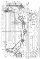
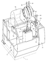
- the combine according to the embodiment includes a traveling machine body 1 supported by a pair of left and right iron crawler belts 2 as a traveling portion.
- a reaping device 3 for capturing uncut cereal grains such as rice (or wheat, soybeans or corn) is mounted by a single-acting lifting hydraulic cylinder 4 so as to be adjustable up and down. ing.
- a cab 5 as a driving part on which an operator gets on board is mounted.
- a Glen tank 6 for storing the grain after threshing is disposed behind the cab 5.
- An engine 7 as a power source is disposed behind the Glen tank 6.
- a grain discharge auger 8 is provided on the right side of the rear part of the Glen tank 6 so as to be able to turn.
- the grain in the Glen tank 6 is carried out, for example, to a truck bed, a container, or the like from the throat throw opening 8a at the tip of the discharge auger 8.
- a threshing device 9 for threshing the harvested cereal meal supplied from the harvesting device 3.
- a grain sorting mechanism 10 for performing swing sorting and wind sorting is arranged.
- the reaping device 3 includes a feeder house 11 that communicates with the handling port 9 a at the front of the threshing device 9, and a horizontally long bucket-like grain header 12 that is provided continuously at the front end of the feeder house 11.
- a scraping auger 13 is rotatably supported in the grain header 12.
- a take-up reel 14 with a tine bar is disposed above the front portion of the take-up auger 13.
- a clipper-shaped cutting blade 15 is disposed in front of the grain header 12.
- a weeding body 16 is provided on both the left and right sides of the front portion of the grain header 12.
- a supply conveyor 17 is provided in the feeder house 11.
- a beater 18 for passing cereals is provided between the feed end of the supply conveyor 17 and the handling port 9a.
- the lower surface part of the feeder house 11 and the front end part of the traveling machine body 1 are connected via the lifting hydraulic cylinder 4, and the reaping device 3 moves up and down by the lifting hydraulic cylinder 4.
- the tip side of the uncut grain culm between the left and right weed bodies 16 is scraped by the take-up reel 14, and the heel side of the uncut grain pod is cut by the cutting blade 15.
- the grain headers 12 are collected in the vicinity of the center of the left and right width.
- the whole amount of the harvested cereal grains of the grain header 12 is conveyed by the supply conveyor 17 and is input to the handling port 9 a of the threshing device 9 by the beater 18.
- the grain header 12 is provided with a horizontal control hydraulic cylinder 19 for rotating the grain header 12 about the horizontal control fulcrum shaft 19a, and the grain header 12,
- the cutting blade 15 and the take-up reel 14 are supported horizontally with respect to the field scene.
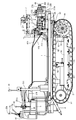
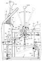
- a handling cylinder 21 is rotatably provided in a handling chamber of the threshing device 9.
- a handling cylinder 21 is pivotally supported on a handling cylinder shaft 20 extended in the front-rear direction of the traveling machine body 1.
- a receiving net 24 (concave) for allowing the grains to leak is stretched below the handling cylinder 21.
- a spiral (screw blade-shaped) intake blade 25 projects outward in the radial direction.
- the harvested cereal mash introduced from the handling port 9 a is kneaded between the handling cylinder 21 and the receiving net 24 while being conveyed toward the rear of the traveling machine body 1 by the rotation of the handling cylinder 21. Threshed.
- the threshing of grains or the like smaller than the mesh of the receiving net 24 leaks from the receiving net 24.
- the sawdust and the like that do not leak from the receiving net 24 are discharged from the dust outlet at the rear of the threshing device 9 to the field by the conveying action of the handling cylinder 21.
- a plurality of dust feeding valves (not shown) for adjusting the conveying speed of threshing in the handling chamber are pivotally mounted on the upper side of the handling cylinder 21 so as to be rotatable.
- the conveying speed (residence time) of threshing in the handling chamber can be adjusted according to the variety and properties of the harvested cereal.
- a rocking sorter 26 for specific gravity sorting having a grain pan, chaff sheave, grain sheave, Strollac and the like is provided as the grain sorting mechanism 10 disposed below the threshing device 9, a rocking sorter 26 for specific gravity sorting having a grain pan, chaff sheave, grain sheave, Strollac and the like is provided.
- the grain sorting mechanism 10 includes a tang fan 29 that supplies sorting wind.
- the threshing that has been threshed by the handling cylinder 21 and leaked from the receiving net 24 is the first of the grains (fine grains, etc.) by the specific gravity sorting action of the swing sorter 26 and the wind sorting of the Kara fan 29, Sorted into second crops such as grain with branch stems and sawdust.
- a first conveyor mechanism 30 and a second conveyor mechanism 31 are provided below the rocking sorter 26, as the grain sorting mechanism 10, a first conveyor mechanism 30 and a second conveyor mechanism 31 are provided below the rocking sorter 26, as the grain sorting mechanism 10, a first conveyor mechanism 30 and a second conveyor mechanism 31 are provided below the rocking sorter 26, as the grain sorting mechanism 10, a first conveyor mechanism 30 and a second conveyor mechanism 31 are provided below the rocking sorter 26, as the grain sorting mechanism 10, a first conveyor mechanism 30 and tang fan 29, the first item such as the grain dropped from the swing sorter 26 is collected in the glen tank 6 by the first conveyor mechanism 30 and the cereal conveyor 32.
- a second thing such as a grain with a branch is returned to the sorting start end side of the swing sorting board 26 via the second conveyor mechanism 31 and the second reduction conveyor 33 and is re-sorted by the swing sorting board 26.
- the sawdust and the like are discharged from the dust outlet 34 at the rear of the traveling machine body 1 to the field.
- the cab 5 is provided with a steering column 41 and a driver seat 42 on which an operator sits.
- left and right traveling speed change levers 43 and 44 as steering levers for changing the course of the traveling machine body 1 and changing the moving speed, and the reaping device 3 are moved up and down by tilting in the front-rear direction.
- a cutting posture lever 45 for raising and lowering the take-up reel 14 by tilting in the horizontal direction, an accelerator lever 46 for controlling the rotation of the engine 7, and a grain discharging lever 47 for operating the grain discharging auger 8. has been. As shown in FIG.
- the cutting clutch lever 39 (working clutch lever) for turning on and off the power transmission of the cutting device 3 and the power transmission of the threshing device 9 are turned on and off.
- a threshing clutch lever 40 (working clutch lever) to be operated is arranged.
- a brake pedal 38 for crawler belt 2 braking is provided below the front portion of the side column 41b.
- a roof 49 for awning is attached to the upper side of the cab 5 via a support column 48.
- the left and right track frames 50 are disposed on the lower surface side of the traveling machine body 1.
- the track frame 50 includes a drive sprocket 51 that transmits the power of the engine 7 to the crawler belt 2, a tension roller 52 that maintains the tension of the crawler belt 2, a plurality of track rollers 53 that hold the ground side of the crawler belt 2 in a grounded state, An intermediate roller 54 for holding the non-grounding side of the crawler belt 2 is provided.
- the rear side of the crawler belt 2 is supported by the drive sprocket 51, the front side of the crawler belt 2 is supported by the tension roller 23, the ground side of the crawler belt 2 is supported by the track roller 53, and the non-ground side of the crawler belt 2 is supported by the intermediate roller 54 To be configured.
- a bottom feed conveyor 60 disposed at the bottom of the Glen tank 6 and a vertical feed conveyor 61 disposed at the rear of the Glen tank 6 are provided.
- the left and right bottom feed conveyors 60 extend in the front-rear direction at the bottom of the grain tank 6 and convey the grains at the bottom of the grain tank 6 toward the lower end side of the vertical feed conveyor 61 provided vertically.
- the vertical feed conveyor 61 is extended in the vertical direction at the rear part of the grain tank 6, and conveys the grain from the upper end side of the vertical feed conveyor 61 toward the feed start end side of the grain discharge auger 8 on the right side of the grain tank 6. .
- the grain in the Glen tank 6 is conveyed to the throat throw port 8a at the tip of the discharge auger 8 (feed end side).
- the grain discharge auger 8 is supported on the upper end side of the vertical feed conveyor 61 so as to be rotatable up and down, and is configured so that the side of the grain discharge auger 8 that is the feed end side of the grain discharge auger 8 can be raised and lowered. Moreover, it is comprised so that the hull spout 8a side of the grain discharge auger 8 can be moved around the conveyor shaft center (horizontal direction) of the vertical feed conveyor 61. That is, the side of the heel throw 8a is moved to the lower side of the front part of the traveling machine body 1, and the grain discharge auger 8 is stored in the right side of the cab 5 and the grain tank 6 via the auger rest 8b.
- the side of the grain discharge auger 8 which is the feed terminal side, is raised, the side of the traveling machine body 1 is moved to the side or rear of the traveling machine body 1, and the side of the traveling machine body 1 is moved backward.
- the grain discharge auger 8 is protruded, and the grain thrower 8a is made to face the loading platform or container of the truck so that the grains in the grain tank 6 are carried out to the loading platform or container of the truck.
- the threshing device 9 includes a handling cylinder 21 for threshing threshing, a rocking sorter 26 for selecting a shed product falling below the handling cylinder 21, and a tang fan 29.
- the front side of the handling cylinder 21 faces the handling port 9a communicating with the feeder house 11, and the rear side of the handling cylinder 21 faces the dust outlet 34 at the rear of the threshing device 9. That is, the rear side of the handling cylinder 21 protrudes further rearward than the rear end of the receiving net 24 that causes the grains to leak.
- a dust exhaust port 34 is provided at the lower rear side of the handling cylinder 21 (an opening portion without the receiving net 24).
- the rotation axis of the handling cylinder 21 extends along the traveling direction (front-rear direction) of the traveling machine body 1.
- the threshed material threshed by the handling cylinder 21 by the inclined plate 119 is brought to the left and right center side of the swing sorter 26.
- the harvested cereal mash that has been introduced into the handling port 9 a of the threshing device through the feeder house 11 and the beater 18 from the reaping device 3 is threshed by the handling cylinder 21.
- the swing sorter 26 located below the receiving net 24 is configured to be able to swing back and forth in a diagonally forward and downward direction via a swing link 35.
- the swing sorter 26 includes a grain pan 36 located below the front portion of the receiving net 24, a movable chaff sheave 37 and a fixed chaff sheave 38 for adjusting the amount of grain leakage, and a movable chaff sheave 37 and the first conveyor mechanism 30. It has the arranged grain sheave 39 and the stroller rack 40 connected to the rear end side of the fixed chaff sheave 39.
- the cereals on the chaff sheaves 37 and 38 are subjected to specific gravity sorting by the chaff sheaves 37 and 38 themselves, and are separated into grains and sawdust by receiving a sorting wind flowing backward from the tang fan 29.
- Kernel (first thing) that has fallen from the movable chaff sheave 37 and the Glen sheave 39 is first collected by the conveyor mechanism 30 while removing the dust in the sorting air of the Kara fan 29.
- the grain taken out from the first conveyor mechanism 30 is carried into and collected in the Glen tank 6 through the cereal conveyor 32.
- the second object that has failed to pass through the movable chaff sheave 37 and the Glen sheave 39 and the second object that has dropped from the fixed chaff sheave 38 are collected by the second conveyor mechanism 31 that is the rearmost of the conveyor mechanism 30.
- the second items collected by the second conveyor mechanism 31 are returned to the upper surface side of the swing sorter 26 via the second reduction conveyor 33 and re-sorted.
- the relatively heavy sawdust on the chaff sheaves 37 and 38 is discharged from the dust outlet 34 to the outside of the machine via the stroller 40.
- a travel speed change pump case 66 having a pair of swash plate variable left and right travel hydraulic pumps 65 is provided.
- the engine 7 is mounted on the upper surface of the right rear portion of the traveling machine body 1, and the pump case 66 is disposed on the upper surface of the traveling machine body 1 on the left side of the engine 7.
- left and right reduction gear cases 63 are provided at the rear ends of the left and right track frames 50, respectively.
- a traveling hydraulic motor 69 is disposed in each of the left and right reduction gear cases 63.
- a travel drive input shaft 64 projecting rearward from the pump case 66 and an output shaft 67 projecting rearward from the engine 7 are connected via an engine output belt 231.
- the engine 7 and the pump case 66 are provided on the upper surface side of the traveling machine body 1 on the rear side of the threshing device 9, and the pump case 66 is disposed between the engine 7 and the threshing device 9.
- a charge pump 68 for driving the lifting hydraulic cylinder 4 and the like is also provided on the same axis 64 as the traveling hydraulic pump 65. Further, a working hydraulic pump 70 for operating the lifting hydraulic cylinder 4 or the horizontal control hydraulic cylinder 19 is disposed in the engine 7, and the charge pump 68 and the working hydraulic pump 70 are connected to the engine 7 in the same manner as the traveling hydraulic pump 65. It is comprised so that it may drive.
- the drive output of the engine 7 is transmitted to the left and right traveling hydraulic pump 65 via the output shaft 67.
- the left and right traveling hydraulic motors 69 are individually driven by the left and right traveling hydraulic pumps 65, and the left and right crawler belts 2 are moved forward and backward by the left and right traveling hydraulic motors 69. Further, the rotational speed of the left and right traveling hydraulic motor 69 is controlled, and the rotational speed of the left and right crawler belts 2 driven by the left and right traveling hydraulic motor 69 is varied to change the moving direction (traveling path) of the traveling machine body 1 and It is configured to perform direction changes on the ground.
- a pair of left and right traveling hydraulic motors 69 are hydraulically connected to the left and right traveling hydraulic pumps 65 via a closed loop hydraulic circuit.
- the left and right crawler belts 2 are driven in the forward direction or the reverse direction via the drive sprocket 51 by the left and right traveling hydraulic motor 69.
- the operator operates the left and right traveling speed change levers 43 and 44 to adjust the swash plate angles (shift control) of the left and right traveling hydraulic pumps 65, whereby the rotational speed or rotational direction of the left and right traveling hydraulic motors 69 can be adjusted.
- the left and right crawler belts 2 are driven independently from each other, and the traveling machine body 1 is configured to move forward or backward.
- a handling cylinder drive case 71 that supports a threshing input shaft 72 is provided.
- a threshing input shaft 72 is connected to the traveling drive input shaft 64 via a threshing drive belt 232.
- the power of the engine 7 is transmitted from the travel drive input shaft 64 to the threshing input shaft 72 via the threshing clutch 233 also serving as a tension roller and the threshing drive belt 232.
- the threshing clutch 233 is controlled to be turned on and off by the operator's lever operation.
- a threshing input shaft 72 is connected to one end side (rear end side) of the barrel 20 via a barrel drive belt 234.
- a cutting selection input case 73 is provided on the front wall of the threshing device 9.
- a cutting selection input shaft 74 is pivotally supported on the cutting selection input case 73.
- One end side (right end portion) of the cutting selection input shaft 74 is connected to the other end side (front end side) of the barrel 20 via a bevel gear 75.
- the other end side (left end portion) of the cutting selection input shaft 74 is connected to the left end portion of the beater shaft 82 on which the beater 18 is pivotally supported via the beater drive belt 238.
- the left end portion of the beater shaft 82 is connected to the left end portion of the hot shaft 76 supporting the hot fan 29 via a selection input belt 235.
- a tang shaft 76 is connected to the left end of the first conveyor shaft 77 of the first conveyor mechanism 30 and the left end of the second conveyor shaft 78 of the second conveyor mechanism 31 via a conveyor drive belt 237.
- a left end portion of a second conveyor shaft 78 is connected to a left end portion of a crank-like swing drive shaft 79 pivotally supported by the rear portion of the swing sorting plate 26 via a swing sorting belt 236.
- the cereal conveyor 32 is driven via the first conveyor shaft 77, and the first selected grain of the first conveyor mechanism 30 is collected in the Glen tank 6.
- the second reduction conveyor 33 is driven via the second conveyor shaft 78, and the second selected grain mixed with the sawdust from the second conveyor mechanism 31 is returned to the upper surface side of the rocking sorter 26.
- the combination of the sorting input belt 235, the swing sorting belt 236, and the conveyor drive belt 237 corresponds to a sorting drive belt for transmitting power to the grain sorting mechanism 10.
- the left end portion of the cutting input shaft 89 on which the feed end side of the supply conveyor 17 is pivotally supported is connected to the left end portion of the beater shaft 82 via a cutting drive belt 241 and a cutting clutch 242.
- the right end of the cutting input shaft 89 is connected to the header drive shaft 91 provided on the grain header 12 via the header drive chain 90.
- a header drive shaft 91 is connected to a drive shaft 93 that supports the drive auger 13 via a drive drive chain 92.
- a header drive shaft 91 is coupled to a reel shaft 94 that supports the take-up reel 14 via an intermediate shaft 95 and reel drive chains 96 and 97.
- the cutting blade 15 is connected to the right end portion of the header driving shaft 91 through a cutting blade driving crank mechanism 98.
- the feed conveyor 17, the auger 13, the hoisting reel 14, and the cutting blade 15 are driven and controlled so as to continuously mow the tip of the uncut grain culm in the field. It is configured.
- a reaping device 3 a threshing device 9 having a handling cylinder 21, and a traveling machine body 1 having a driver's seat 42 are provided.
- the engine 7 is mounted on the rear part of the traveling machine body 1, and the power of the engine 7 is transmitted to the rear end side of the handling cylinder 20 on which the handling cylinder 21 is pivotally supported.
- the power of the engine 7 is transmitted from the front end side of the handling cylinder shaft 20 to the cutting device 3 and the beater 18, the beater 18 is driven via the handling cylinder shaft 20, and the cutting device 3 is driven via the beater 18.
- the large reaping device 3 having a wide cutting width can be stably supported, and the front-rear balance of the traveling machine body 1 can be improved. That is, it is possible to improve harvesting workability in wet fields or mobility on rough roads. Further, since the power of the engine 7 is transmitted to the beater 18 and the reaping device 3 using the handling cylinder 20, even if the reaping device 3 and the engine 7 are provided apart from each other, the engine 7 is connected to the beater 18 or the reaping device 3.
- the transmission path can be easily configured. That is, the maintenance workability of the drive structure such as the reaping device 3 or the threshing device 9 can be improved.
- the rear end side of the bottom feed conveyor shaft 103 of the bottom feed conveyor 60 is connected to the rear end portion of the travel drive input shaft 64 via the grain discharge belt 244 and the grain discharge clutch 245.
- One end side of the lower mediation shaft 105 is connected to the rear end portion of the bottom feed conveyor shaft 103 via a longitudinal feed drive chain 104.
- the other end side of the mediation shaft 105 is connected to the lower end side of the vertical feed conveyor shaft 106 of the vertical feed conveyor 61 via a bevel gear mechanism 107.
- One end side of the upper intermediate shaft 109 is connected to the upper end side of the vertical feed conveyor shaft 106 via a bevel gear mechanism 108.
- One end side of the grain discharge shaft 111 is connected to the other end side of the upper mediation shaft 109 via the grain discharge drive chain 110.
- the feed start end side of the discharge auger shaft 112 of the grain discharge auger 8 is connected to the other end side of the grain discharge shaft 111 via a bevel gear mechanism 113.
- front and rear grain discharge ports 221 and 222 are provided at the bottom of the Glen tank 6.
- the wrinkle receiving base 223 is arrange
- An operator other than the operator of the driver's seat 42 rides on the saddle cradle 223 in a state where the saddle cradle 223 is supported in a horizontal working posture, and attaches a saddle bag to a saddle catcher (not shown).
- the grain in the Glen tank 6 is discharged into the bag.
- the straw bag filled with the grain is dropped from the straw catcher 223 to the field and collected.
- the grains in the grain tank 6 can be discharged without interrupting the mowing and threshing operation. That is, compared with the work of discharging the grain in the grain tank 6 from the grain discharge auger 8, there is almost no need to interrupt the mowing and threshing work. Work efficiency can be improved.
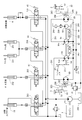
- the combine hydraulic structure and the travel drive structure will be described with reference to FIGS.
- the hydraulic actuator the harvesting lifting hydraulic cylinder 4, the horizontal control hydraulic cylinder 19, the left and right reel lifting hydraulic cylinders 251 that support the take-up reel 14 so as to be lifted and lowered, and the grain
- An auger lifting / lowering hydraulic cylinder 252 that supports the discharge auger 8 to be movable up and down is provided.
- the working hydraulic pump 70 is hydraulically connected to the horizontal control hydraulic cylinder 19 through a horizontal control electromagnetic hydraulic valve 253 that is controlled by operation of the horizontal control switch 254.
- the horizontal control switch 254 When the operator operates the horizontal control switch 254 to operate the horizontal control hydraulic cylinder 19, the left-right inclination of the traveling machine body 1 is maintained at a horizontal or arbitrary inclination.
- a horizontal control switch is provided at the upper end of the cutting posture lever 45.
- the working hydraulic pump 70 is hydraulically connected to the cutting lift hydraulic cylinder 4 via the cutting lift manual hydraulic valve 255.
- the cutting lifting / lowering hydraulic cylinder 4 is actuated so that the operator moves the cutting device 3 up and down to an arbitrary height (for example, cutting height or non-working height). It is configured.
- the working hydraulic pump 70 is hydraulically connected to the reel lifting hydraulic cylinder 251 through the reel lifting manual hydraulic valve 256.
- the reel lifting hydraulic cylinder 251 is actuated, and the operator lifts and lowers the take-up reel 14 to an arbitrary height to harvest the uncut grain culm on the field. .
- the working hydraulic pump 70 is hydraulically connected to the auger lifting hydraulic cylinder 252 via the auger lifting manual hydraulic valve 257.
- the auger lifting / lowering hydraulic cylinder 252 is operated, and the operator moves the cocoon throwing port 8a of the grain discharging auger 8 up and down to an arbitrary height.
- the grain discharge auger 8 is rotated in the horizontal direction by an electric motor (not shown), and the cocoon throwing port 8a is moved in the horizontal direction.
- the culling spout 8a is positioned above the truck bed or container, and the grains in the grain tank 6 are discharged into the truck bed or container.
- left and right traveling hydraulic motors 69 are hydraulically connected to the left and right traveling hydraulic pumps 65 via left and right closed hydraulic circuits 261, respectively.
- the left and right traveling speed change levers 43 and 44 are connected to the output adjustment swash plate 65a of the left and right traveling hydraulic pump 65 via the servo valve mechanism 262, respectively, so that the left and right traveling speed change levers 43 and 44 are inclined in the front-rear direction.
- the support angle of the output adjustment swash plate 65a is changed proportionally.
- the left and right traveling hydraulic motors 69 are respectively driven by the left and right traveling hydraulic pumps 65, and the driving force of the left and right traveling hydraulic motors 69 is transmitted to the left and right crawler belts 2 via the reduction gear mechanism 263 of the reduction gear case 63, respectively.
- the left and right crawler belts 2 are driven forward or backward.
- the traveling body 1 can move straight in the forward direction at a vehicle speed proportional to the inclination angle of the left and right traveling speed change levers 43 and 44.
- the vehicle can move straight in the backward (reverse) direction at a vehicle speed proportional to the tilt angle of the left and right traveling speed change levers 43 and 44.
- the left and right traveling speed change levers 43 and 44 have different inclination angles to the front of the machine
- the left and right traveling speed change levers 43 and 44 have different inclination angles to the rear of the machine, or the left and right traveling speed change levers.
- the left and right traveling speed change levers 43 and 44 are inclined at a vehicle speed proportional to the inclination angle of the left and right traveling speed change levers 43 and 44.
- the traveling machine body 1 can be turned in the left-right direction with a turning radius proportional to the angle difference.
- a left and right closed hydraulic circuit 261 is connected to the high pressure oil discharge side of the charge pump 68 via an oil cooler 264 and a line filter 265 so that the hydraulic oil in the oil tank 266 is supplied to the left and right closed hydraulic circuits 261. It is configured.
- An oil tank 266 is mounted on the upper surface of the traveling machine body 1 on the left side of the fuel tank 267 of the engine 7, and the driver's seat 42 is disposed above the fuel tank 267 via a seat frame 268.
- the pump case 66 in which the left and right traveling hydraulic pumps 65 are built is mounted on the engine 7 mounted on the right upper surface of the rear portion of the traveling machine body 1 and on the left upper surface of the traveling machine body 1.
- the threshing device 9 is fixed to the upper surface side of the traveling machine body 1 via the front support body 271 and the rear support body 272 between the right side wall body of the threshing device 9.
- a U-shaped intermediate portion of the front support body 271 is fastened to the upper surface of the traveling machine body 1 with bolts 273.
- the left and right sides of the pump case 66 are fastened with bolts 274 to both U-shaped ends of the front support 271. That is, the front part of the pump case 66 in which the charge pump 68 is disposed is supported by the traveling machine body 1 by the front support body 271.
- the bottom surface side of the rear support body 272 is fastened to the mounting base 275 on the upper surface side of the traveling machine body 1 with bolts 276.
- the rear side of the pump case 66 is fastened to the front side of the rear support 272 with bolts 277.
- a support arm body 272a extends rearward from the rear surface of the rear support body 272, and the lower end side of the rear bearing body 278 is fastened to the rear end portion of the support arm body 272a with a bolt 279.
- the rear end side of the travel drive input shaft 64 protrudes rearward from the rear surface of the pump case 66, and the travel drive input shaft 64 is passed through the rear support body 272 and the rear bearing body 278.
- a grain discharge drive pulley 282 around which the grain discharge belt 244 is wound is pivotally supported at the rear end portion of the travel drive input shaft 64 protruding rearward from the rear bearing body 278. That is, an engine output transmission pulley 280, a threshing output transmission pulley 281 and a grain discharge driving pulley 282 as counter pulleys are pivotally supported on a travel drive input shaft 64 as a counter shaft.
- an engine output pulley 283 is pivotally supported on the output shaft 67 of the engine 7, and the engine output belt 231 is wound between the engine output transmission pulley 280 and the engine output pulley 283.
- a large-diameter threshing input pulley 284 is pivotally supported on one end side of the threshing input shaft 72, and a threshing driving belt 232 is wound between the threshing output transmission pulley 281 and the large-diameter side threshing input pulley 284.
- a small-diameter threshing input pulley 285 is pivotally supported on the other end side of the threshing input shaft 72, and a barrel driving belt 234 is disposed between the barrel input pulley 286 on the barrel shaft 20 and the small-diameter threshing input pulley 285. Wrap around. Further, a grain discharge pulley 287 is pivotally supported on the rear end side of the bottom feed conveyor shaft 103, and a grain discharge belt 244 is wound between the grain discharge drive pulley 282 and the grain discharge pulley 287.
- the driving force output from the engine 7 is branched and transmitted by the travel drive input shaft 64 as a counter shaft. That is, the output of the engine 7 is transmitted from the travel drive input shaft 64 to the left and right travel hydraulic pumps 65. Further, the output of the engine 7 is transmitted from the threshing output transmission pulley 281 on the traveling drive input shaft 64 to the barrel shaft 20 of the threshing device 9 via the threshing drive belt 232 and the barrel driving belt 234. On the other hand, the output of the engine 7 is transmitted from the grain discharge drive pulley 282 on the travel drive input shaft 64 to the grain discharge auger 8 via the grain discharge belt 244.
- the engine 7 is mounted on the rear portion of the traveling machine body 1
- the threshing device 9 and the grain tank 6 are provided on the traveling machine body 1
- the reaping device is disposed in front of the threshing device 9.
- a travel drive input shaft 64 as a counter shaft parallel to the output shaft 67 of the engine 7 and at the same height position, an engine output pulley 283 on the output shaft 67, and a counter on the counter shaft 64 Since the engine output transmission pulley 280 or the threshing output transmission pulley 281 or the grain discharge drive pulley 282 as the pulley and the threshing input pulley 284 of the threshing device 9 are arranged flush with the rear surface of the traveling machine body 1, the engine 7 for compactly assembling the threshing drive belt 232 or the like for transmitting power from the threshing device 7 to the rear surface side of the engine 7 or the rear surface side of the threshing device 9 Kill.
- the engine output transmission pulley 280 on which the output belt 231 of the engine 7 is suspended can be disposed at a position where vibration of the engine 7 is reduced. Further, by opening the rear portion of the traveling machine body 1, replacement or maintenance work of the output belt 231 of the engine 7 or the threshing driving belt 232 of the threshing device 9 can be easily performed from the rear side of the traveling machine body 1. That is, the handling workability can be improved while the power transmission structure of the engine 7 can be simplified.
- the left and right traveling hydraulic pumps 65 and the left and right traveling hydraulic motors 69 are provided, and the left and right traveling hydraulic motors 69 are operated by the left and right traveling hydraulic pumps 65. Since the left and right traveling hydraulic pumps 65 are disposed on the traveling drive input shaft 64, the traveling hydraulic pump 65 can be installed compactly in the engine room adjacent to the engine 7. Further, the traveling hydraulic pump 65 can be easily air-cooled by the cooling air of the engine 7. The driving efficiency of the crawler belt 2 can be improved while the hydraulic piping structure of the left and right traveling hydraulic pumps 65 and the left and right traveling hydraulic motors 69 can be simplified.
- the engine 7 is mounted on the traveling machine body 1 below the rear part of the Glen tank 6, and the grain discharge pulley 287 of the Glen tank 6 is attached to the rear surface of the traveling machine body 1.
- , 281, 282 are arranged flush with each other, so that the rear part of the traveling machine body 1 is opened, so that the grain discharge belt 244 of the grain tank 6 can be replaced or maintained from the rear side of the traveling machine body 1. Easy to execute. While the power transmission structure to the Glen tank 6 can be simplified, handling workability can be improved.
- a beater 18 and a beater shaft 82 for passing cereals are arranged below a cutting selection input shaft 74 that protrudes leftward and rightward from the cutting selection input case 73 at the front of the threshing device 9. Yes.
- Power is transmitted from the cutting selection input shaft 74 to the beater shaft 82 via the beater drive belt 238.
- the power transmitted to the beater shaft 82 is distributed by being distributed back and forth on the left wall side of the threshing device 9 toward the reaping device 3 and the grain sorting mechanism 10.
- power is transmitted from the beater shaft 82 to the cutting input shaft 89 that pivotally supports the feed end side of the supply conveyor 17 via the cutting drive belt 241 and the cutting clutch 242, and to the cut shaft through the selection input belt 235. Power is transmitted to 76.
- the cutting input shaft 89 and the tang shaft 76 are located further below the beater shaft 82.
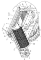
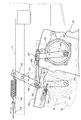
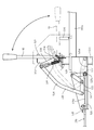
- the outer surface side of the left wall in the threshing device 9 is covered with a total of four cover bodies 121 to 124 arranged vertically and front and back.
- These cover bodies 121 to 124 are basically for protecting the movable parts (pulleys, belts, etc.) on the left side of the combine.
- the lower front cover body 123 covers and conceals the movable parts of the cutting input shaft 89 and the red pepper shaft 76, and the lower rear cover body 124 conceals the movable parts behind the red pepper shaft 76 in the grain sorting mechanism 10.
- the upper front cover body 121 covers the movable parts of the cutting and sorting input shaft 74 and the beater shaft 82, and the upper rear cover body 122 as a lateral plate covers the left side portion of the handling cylinder 21.
- the lower front and rear cover bodies 123 and 124 and the upper front cover body 121 are detachably mounted on the outer surface side of the left side wall body in the threshing device 9.
- the upper rear cover body 122 is provided so as to be able to open and close in the horizontal direction with the vertical axis 125 on the front side as a rotation fulcrum. That is, the pair of upper and lower horizontal frames 126 that are strength members of the upper rear cover body 122 has a front end side protruding from the front end surface of the upper rear cover body 122.
- the projecting end portions of the horizontal frames 126 are pivotally mounted on the vertical axis 125 at two upper and lower support stay portions 127 provided on the front outer surface side of the left wall.
- a rectangular opening 128 is formed on the upper side of the left wall of the threshing device 9 so that the handling cylinder 21 can face.
- the rectangular opening 128 of the threshing device 9 is closed, and if the upper rear cover body 122 is opened, the handling cylinder 21 and the right receiving net 24b facing the rectangular opening 128 (details) Will be exposed later).
- the movable part of the cutting selection input shaft 74 and the beater shaft 82, the movable part of the cutting input shaft 89, and the movable part of the grain sorting mechanism 10 are arranged around the upper rear cover body 122. And is provided so as to bypass the upper rear cover body 122. Therefore, although both the movable parts and the upper rear cover body 122 are on the left wall side of the threshing device 9, the opening and closing rotation around the vertical axis 125 of the upper rear cover body 122 interferes with the movable parts. Absent.
- the receiving network 24 of the embodiment is a concave type formed in a lattice shape, and is configured by a combination of a pair of receiving network portions 24a and 24b that can be divided in the left-right direction.
- the right receiving net portion 24b near the right wall of the threshing device 9 is fixed to the front wall, the right wall, and the like of the threshing device 9.
- the left receiving mesh portion 24 a located near the upper rear cover body 122 is fixed to the inner surface side of the upper rear cover body 122 so as to rotate integrally with the upper rear cover body 122.
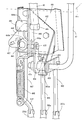
- a front and rear longitudinal locking pin body 129 is provided on the outer surface side of the rear wall body in the threshing device 9.
- a hook lever 130 that is detachably hooked and engaged with the locking pin body 129 on the rear wall body side is provided so as to be rotatable.
- the hook lever 130 is always biased by a tension spring 131 in a direction in which the hook lever 130 is hooked and engaged with the locking pin body 129.
- An operation hole 132 through which the handle shaft portion of the hook lever 130 passes is provided on the rear side of the upper rear cover body 122.
- the upper front cover body 121 When opening the upper rear cover body 122, the upper front cover body 121 is removed in advance, and then the hook lever 130 is rotated in the disengagement direction to open and rotate the upper rear cover body 122 leftward. You can do it. Then, the upper rear cover body 122 rotates around the vertical axis together with the left receiving mesh portion 24a, and the handling cylinder 21 and the right receiving mesh portion 24b in the threshing device 9 are exposed. When closing the upper rear cover body 122, it is only necessary to push the free end side of the upper rear cover body 122 toward the threshing device and to close and rotate it in the right direction.
- the cutting device 3 including the cutting blade 15 and the threshing device 9 including the handling cylinder 21 and the receiving net 24 are provided, and the threshing device 9 is connected to the threshing device 9 via the feeder house 11 and the beater 18. It is a normal combine that supplies the harvested cereal rice cake, and a grain tank 6 is arranged on one side of the left and right sides of the threshing device 9, and the left and right other sides of the threshing device 9 are opened and closed around a vertical axis 125.
- a possible lateral side plate 122 is provided, and the handling cylinder 21 and the receiving net 24 in the threshing device 9 are exposed by opening and turning the lateral side plate 122, so that the mounting height of the lateral side plate 122 is almost changed. Without this, the lateral plate 122 can be opened and closed. For this reason, it is easy to open and close the lateral side plate 122 regardless of the height of the operator, and there is no inconvenience of the opening and closing operation as in the prior art. Further, since the lateral plate 122 is configured to open / close and rotate around the vertical axis 125, that is, to rotate horizontally, the lateral plate 122 is opened even without an actuator such as a gas cylinder as in the prior art. Can be maintained. For this reason, it is not necessary to secure the space for arranging the actuator, the number of parts can be reduced, and the manufacturing cost can be reduced.
- the receiving net 24 is configured by a combination of a pair of receiving net parts 24 a and 24 b that can be divided in the left-right direction, and the left receiving net part 24 a near the lateral side plate 122 rotates integrally with the lateral side plate 122.
- the left receiving mesh portion 24a is also opened and rotated around the longitudinal axis 125 together with the lateral side plate 122. become. For this reason, the side space around the handling cylinder 21 and the receiving net 24 in the threshing device 9 can be greatly opened, and cleaning work and maintenance work are easy to perform.
- a grain selection mechanism 10 is provided below the lateral plate 122 in the threshing device 9, and the beater 18 is disposed between the feeder house 11 and the threshing device 9.
- the power of the engine 7 that is disposed below the front end side of the front and rear longitudinal barrel shaft 20 that pivotally supports and is mounted on the rear portion of the traveling machine body 1 is transmitted to the beater 18 via the barrel shaft 20,
- the power transmitted to the beater 18 is distributed and distributed back and forth on the other side of the threshing device 9 toward the reaping device 3 and the grain sorting mechanism 10.
- both the power transmission system to the grain sorting mechanism 10 and the lateral plate 122 are on the other side of the threshing device 9, the power transmission system to the reaping device 3 and the grain sorting mechanism 10 is provided. Bypassing the side plate 122 It is is will be. For this reason, both the maintenance work of the handling cylinder 21 and the receiving net 24 and the maintenance work for the power transmission system to the harvesting device 3 and the grain sorting mechanism 10 are performed from the opposite side of the Glen tank 6 installation side. It can be executed easily and maintenance workability is improved.
- a pedal frame 275 is erected from the cab 5 and the base end portion of the brake pedal 38 is pivotally supported on the pedal frame 275 via a pedal fulcrum shaft 276.
- One end side of the brake wire 278 is connected to the base end portion of the brake pedal 38 via the wire arm 277.
- a pedal return spring 280 is connected to the base end portion of the brake pedal 38 via a spring arm 279. The pedal return spring 280 is configured to support the stepping portion 38a of the brake pedal 38 at the raised position.
- the side column frame 281 forming the side column 41b includes an upper frame 281a that extends horizontally in the front-rear direction, a front column 281b that supports the front end portion of the upper frame 281a, It has an auxiliary column 281c erected in parallel with the front side of the column 281b, and an auxiliary upper frame 281d that connects the upper end of the column 281c to the front column 281b.
- the brake pedal 38 comes into contact with the lower surface of the auxiliary upper frame 281d, and the brake pedal 38 is supported at the raised position by the pedal return spring 280.
- the parking lever 283 is rotatably supported by the auxiliary column 281c and the auxiliary upper frame 281d via the upper and lower brackets 282.
- the pedal hook body 283a of the parking lever 283 is locked to the brake pedal 38, and the brake pedal is resisted against the pedal return spring 280.
- 38 is configured to be supported in a downward movement (braking) position.
- a release spring 284 for supporting the parking lever 283 is provided at a position where the pedal hook body 283a is not locked to the brake pedal 38.
- the brake wire 278 is provided with a brake link 286 that connects the upper end side via a brake spring 285.
- An intermediate portion of the brake link 286 is pivotally supported on the traveling machine body 1 via a link support shaft 287.
- a lower end side of the brake link 286 is connected to a brake braking lever 296 provided in the left traveling hydraulic motor 69 via a pin shaft body 288 and a long hole 289.
- a brake brake lever 296 provided on the right traveling hydraulic motor 69 is connected to the pin shaft body 288 via a bolt shaft body 290 and a connection shaft body 291 whose connection length can be adjusted.
- a lever return stopper body 292 that supports the brake brake lever 296 at the brake release position, and a brake release spring 293 that supports the brake brake lever 296 in contact with the lever return stopper body 292 are provided.
- a lever return stopper body 292 is provided on the left traveling hydraulic motor 69, and a brake release spring 293 is connected between the brake braking lever 296 provided on the left traveling hydraulic motor 69 and the lever return stopper body 292.
- a shift lever fulcrum shaft 411 that pivotally supports the left and right traveling shift levers 43 and 44 so as to be pivotable in the front-rear direction on the upper frame 281a of the side column frame 281 forming the side column 41b.
- the shift lever fulcrum shaft 411 is passed through the upper frame 281a, and the middle portion of the shift lever fulcrum shaft 411 is fixed to the upper frame 281a.
- the base end portions of the left and right traveling shift levers 43 and 44 and the middle portions of the left and right lever operation plates 412 and 413 are rotated to the left and right ends of the shift lever fulcrum shaft 411 protruding in the left-right direction from the upper frame 281a.
- the left shift lever 43 and the left lever operation plate 412 are fixed together.
- the right travel shift lever 44 and the right lever operation plate 413 are integrally fixed.
- the left shift lever 43 (left lever operation plate 412) and the right shift lever 44 (right lever operation plate 413) are supported by the shift lever fulcrum shaft 411 so as to rotate independently. Yes.
- interlocking detent ball mechanism 414 that removably connects the left and right lever operation plates 412 and 413, the upper end sides of the left and right lever operation plates 412 and 413 are engaged by the interlocking detent ball mechanism 414, When either one of the left and right traveling speed change levers 43 and 44 is operated, the other is operated in conjunction with an operation load equal to or less than the engaging force of the interlocking detent ball mechanism 414. When the operation load is greater than the engaging force of the interlocking detent ball mechanism 414, only one traveling speed change lever 43 or 44 on the side where the operation is performed is operated.
- one end sides of the left and right shift push-pull wires 415 and 416 are connected to the lower end sides of the left and right lever operation plates 412 and 413 via the left and right wire connecting shaft bodies 419a and 419b, respectively.
- the other end sides of the left and right shift push-pull wires 415 and 416 are connected to a servo valve mechanism 262 for switching the output adjusting swash plate 65a.
- Either one or both of the left and right traveling hydraulic pumps 65 are controlled to rotate forward by tilting the front of either one or both of the left and right traveling shift levers 43 and 44, and either one or both of the left and right crawler belts 2 are controlled. Is driven forward.
- one or both of the left and right traveling hydraulic pumps 65 are reversely controlled by a tilting operation to the rear side of either one or both of the left and right traveling speed change levers 43, 44, and either one of the left and right crawler belts 2 or Both are driven backwards.
- the course of the traveling machine body 1 is changed by changing the amount of tilting operation of the left and right traveling speed change levers 43 and 44, and turning (U-turn) or the like on the field headland is executed.
- Left and right neutral detent ball mechanisms 417 and 418 detachably connected to the engagement notches 412a and 413a of the left and right lever operation plates 412 and 413 are provided.
- Left and right neutral detent ball mechanisms 417 and 418 are provided on both sides of the upper frame 281a.
- a switch base 421 provided on the front column 281b, a reverse switch 422 provided on the switch base 421, and a reverse sensor arm 423 for operating the switch arm 422a of the reverse switch 422 are provided.
- a reverse sensor arm 423 is provided on the switch base 421.
- reverse operation arms 424 are provided on the left and right lever operation plates 412 and 413, respectively. When either one or both of the left and right speed change levers 43 and 44 are operated in reverse, the reverse operation arm 424 is brought into contact with the reverse sensor arm 423 and the reverse switch 422 is operated to notify the reverse operation. ing.
- a pair of clamping plate bodies 427 for simultaneously clamping the left and right wire connecting shaft bodies 419a and 419b is provided.
- One end side of a pair of sandwiching plate bodies 427 is rotatably connected to the upper frame 281a via a pivoting plate body 428.
- One end side of the pair of tension links 429 is connected to the other end side of the pair of sandwiching plate bodies 427, respectively.
- One end of a tension rod 430 whose length is adjustable is connected to the other end of the pair of tension links 429.
- the pedal arm portion of the brake pedal 38 is connected to the other end side of the tension rod 430.
- the reaping device 3, the threshing device 9 having a handling cylinder 21, and the traveling machine body 1 having a driver's seat 42 are provided, and cereals are supplied from the reaping device 3 to the threshing device 9.
- the harvesting posture lever 45 is provided as a harvesting operation lever in the steering column 41 in front of the driver seat 42 and the left and right traveling speed change levers 43 and 44 are provided in the steering column 41 on the side of the driver seat 42.
- the left and right traveling units 2 can be controlled by operating the shift levers 43 and 44, respectively.
- the operator sitting on the driver's seat 42 can switch the left and right traveling shift levers 43 and 44 by left hand operation, and the cutting posture lever 45 can be switched by the right hand operation of the operator, thereby improving the maneuverability.
- the operator can operate the cutting posture lever 45 with the right hand to move the take-up reel 14 up and down while raising and lowering the cutting device 3, while the operator moves the left and right with the left hand.
- the vehicle speed (movement speed) can be changed by a speed change operation while operating the travel speed change levers 43 and 44 and changing the course by a left and right turning operation.
- the cutting posture operation of the cutting device 3 provided with the take-in reel 14 or the like can be simplified. It is possible to improve the cutting workability in a field that requires a vehicle speed (moving speed) change operation or a course change operation, such as a field where grain cereals are partially lying down.
- a cutting machine 3 As shown in FIGS. 1, 5, 8, and 18 to 21, a cutting machine 3, a threshing device 9 having a handling cylinder 21, and a traveling machine body 1 having a crawler belt 2 as left and right traveling units are provided.
- the combine that supplies the cereal meal from the device 3 to the threshing device 9 has a structure in which a reduction gear case 63 as a left and right reduction case for independently driving the left and right crawler belts 2 is provided. Since the brake mechanisms 297 are respectively arranged and the left and right brake mechanisms 297 are connected to the brake pedal 38 as a single brake operating tool of the cab 5 as the driving operation unit, the left and right brake mechanisms 297 are operated by operating the brake pedal 38.
- the brake mechanism 297 can be operated simultaneously, and the left and right crawler belts 2 can be braked simultaneously.
- the traveling machine body 1 can be stopped without changing the moving direction (the course) of the traveling machine body 1. Further, for example, even if the brake pedal 38 and the left and right brake mechanisms 297 are installed separately from the front and rear parts of the traveling machine body 1, the braking operation structure of the left and right crawler belts 2 can be reduced in cost. It can be configured simply.
- the left and right traveling hydraulic motors 69 provided in the left and right reduction gear cases 63 are arranged with their installation positions shifted in the front-rear direction of the traveling machine body 1.
- a brake link 286 as a brake lever is provided in the traveling machine body 1 located in the middle, and a brake pedal as a brake operation tool is provided via a brake link 286 to the left and right brake mechanisms 297 provided on the left and right traveling hydraulic motor 69 axes.
- the left and right traveling hydraulic motors 69 can be disposed close to each other in the left-right width direction of the traveling machine body 1, and a traveling unit braking operation structure for coupling the brake pedal 38 to the left and right brake mechanisms 297 is provided. It can be configured at low cost and simply.
- the brake pedal 38 at the front part of the traveling machine body 1 and the left and right brake mechanisms 297 at the rear part of the traveling machine body 1 can be easily connected by a single brake wire 278 that brakes the left and right brake mechanisms 297.
- the braking force of the brake mechanism 297 can be easily adjusted, and the maintenance workability can be improved.
- the left and right traveling speed change levers 43 and 44 are provided on the cab 5, and the left and right traveling speed change levers 43 and 44 are operated by stepping on the brake pedal 38 as a brake operating tool.
- the left and right crawler belts 2 can be braked by setting the travel shift to neutral (running drive output is zero) only by the braking operation of the brake pedal 38. It is possible to prevent the traveling hydraulic pump 65 or the traveling hydraulic motor 69 from being overloaded by eliminating the difference between the timing for returning the left and right traveling shift levers 43 and 44 to the neutral position and the timing for braking the left and right crawler belts 2.
- the hydraulic structure for driving the crawler belt 2 incorporating the traveling hydraulic pump 65 or the traveling hydraulic motor 69, or the operation for stopping the left and right crawler belts 2 and the like. That is, while the manufacturing cost of the hydraulic structure for driving the crawler belt 2 can be easily reduced, handling operability such as maintenance of the hydraulic structure for driving the crawler belt 2 can be improved. Further, an emergency stop can be performed by omitting the neutral return operation of the left and right traveling speed change levers 43 and 44, and the slippage of the crawler belt 2 or the excavation of a farm scene can be reduced.
- a lever fulcrum chassis 441 is fixed to the inner surface of the front column 41 a that is erected from the cab 5.
- the lever fulcrum frame 442 is bolted to the lever fulcrum chassis 441.
- a left / right rotation fulcrum shaft 443 is fixed to the lever fulcrum frame 442.
- a left-right rotation frame 444 is provided that is supported to be rotatable about a left-right rotation fulcrum shaft 443 extending in the front-rear direction of the machine body.
- the left and right rotation boss 444a and the front and rear rotation boss 444b are integrally fixed to the left and right rotation frame 444.
- left and right rotation boss 444a is pivotally supported on the left and right rotation fulcrum shaft 443.
- a front / rear rotation fulcrum shaft 445 is pivotally supported on the front / rear rotation boss 444b.
- a base end portion of the cutting posture lever 45 and an upper end portion of the front / rear rotation frame 446 are integrally fixed to a front / rear rotation fulcrum shaft 445 extending in the left-right direction of the machine body.
- a fulcrum side frame 453 for fixing one end side to the lever fulcrum frame 442 is provided as shown in FIGS.
- the lever fulcrum boss portion 453a is integrally fixed to the fulcrum side frame 453.
- the base end portion 47a of the grain discharge lever 47 is passed through the fulcrum side frame 453 and the lever fulcrum boss portion 453a, and the grain discharge lever 47 is pivotally supported by the lever fulcrum boss portion 453a so as to be rotatable in the front-rear direction.
- An intermediate portion of an L-shaped cutting lift link 454 is rotatably supported on the base end portion 47 a of the grain discharge lever 47.
- a vertically long locking groove 446 a is formed on the lower end side of the front / rear rotating frame 446.
- An engagement shaft body 455 is provided on one end side of the L shape of the cutting lift link 454, and the engagement shaft body 455 is slidably engaged in the locking groove 446a.
- the upper end side of the plate-shaped cutting rod lifting / lowering cooperative rod body 456 is connected to the L-shaped other end side of the cutting lifting link 454.
- the lower end side of the cutting / lifting cooperation rod body 456 is connected to the cutting lifting / lowering spool 255a of the manual lifting / lowering hydraulic valve 255.
- the cutting lifting link 454 is moved around the base end portion 47a of the grain discharge lever 47.
- the upper end side of the plate-shaped reel ascending / descending cooperation rod body 458 is connected to the left / right rotation frame 444 via the pivot shaft 457.
- the lower end side of the reel lifting / lowering cooperative rod body 458 is connected to the reel lifting / lowering spool 256a of the reel lifting / lowering manual hydraulic valve 256. That is, by turning the cutting posture lever 45 about the left and right rotation fulcrum shaft 443 and tilting the cutting posture lever 45 in the left and right direction of the machine body, the left and right rotation frame 444 rotates about the left and right rotation fulcrum shaft 443.
- the reel raising / lowering linkage rod body 458 is moved up and down, the reel raising / lowering spool 256a is operated, the reel raising / lowering manual hydraulic valve 256 is switched, the reel raising / lowering hydraulic cylinder 251 is operated, and the take-up reel 14 is moved up and down. It is configured to make it.
- the grain discharge link 459 is fixed to the base end portion 47a of the grain discharge lever 47.
- the upper end side of the plate-shaped conveyor lifting / lowering cooperation rod body 460 is connected to the grain discharge link 459.
- the lower end side of the conveyor lifting / lowering cooperation rod body 460 is connected to the auger lifting / lowering spool 257a of the auger lifting / lowering manual hydraulic valve 257. That is, by turning the grain discharge lever 47 around the axis of the base end 47a and tilting the grain discharge lever 47 in the longitudinal direction of the machine body, the grain discharge link 459 is turned and the conveyor lifting / lowering cooperation is performed.
- the rod body 460 is moved up and down to operate the auger lifting and lowering spool 257a, to switch the auger lifting and lowering manual hydraulic valve 257 and to operate the auger lifting and lowering hydraulic cylinder 252 and It is configured to move up and down.
- the manual lifting / lowering manual hydraulic valve 255, the reel lifting / lowering manual hydraulic valve 256, and the auger lifting / lowering manual hydraulic valve 257 are formed in a harvesting hydraulic valve unit body 258 structure with a single hydraulic valve block, It is attached to the upper surface of the valve support 461 provided on the step floor 5 b of the cab 5.
- the valve support 461 is disposed at the bottom of the front column 41a.
- the accelerator lever 46 is connected to an engine rotation control mechanism attached to the engine 7 via an accelerator wire 462.
- a threshing device 3 As shown in FIG. 1 and FIGS. 17 to 20, a threshing device 3, a threshing device 9 having a handling cylinder 21, and a traveling machine body 1 having crawler belts 2 as left and right traveling units are provided.
- An upper frame 281a serving as a side column frame that forms part of the side column 41b is a structure in which left and right traveling speed change levers 43 and 44 are provided on a side column 41b in the vicinity of the driver seat 42 in a combine that supplies grain cereal to
- left and right traveling speed change levers 43 and 44 and neutral detent ball mechanisms 417 and 418 as a neutral maintaining mechanism for supporting the left and right traveling speed change levers 43 and 44 at the traveling speed neutral position are disposed.
- the left and right traveling speed change levers 43 and 44 are arranged close to each other, and the operator can easily operate each lever 43 and 44 with one hand.
- the left and right traveling speed change levers 43 and 44 are supported at the zero travel speed position by the neutral detent ball mechanisms 417 and 418, so that the operator clearly recognizes the forward and backward operation of the left and right traveling speed change levers 43 and 44.
- the vehicle speed can be changed by appropriately shifting the left and right traveling speed change levers 43, 44, the operator operates one or both of the left and right traveling speed change levers 43, 44 with one hand.
- the steering operation for changing the course (moving direction) of the traveling machine body 1 can be easily performed. It is possible to improve the maneuverability in the harvesting operation performed continuously for a long time.
- left and right neutral detent ball mechanisms 417 and 418 that respectively support the left and right traveling speed change levers 43 and 44 independently of the traveling speed neutral position are provided and directed toward the front and rear direction of the traveling machine body 1.
- Left and right traveling speed change levers 43 and 44 and left and right neutral detent ball mechanisms 417 and 418 are disposed on both sides of the upper frame 281a with the extending upper frame 281a interposed therebetween. Therefore, the left and right neutral detent ball mechanisms 417 and 418 can be installed with high precision so as to face the left and right travel shift levers. 44 can be prevented from being supported at an inappropriate position.
- left and right traveling hydraulic pumps 65 for driving the left and right crawler belts 2 are provided and the outputs of the left and right traveling hydraulic pumps 65 are switched by the left and right traveling shift levers 43 and 44, respectively, Is supported at the neutral position for traveling, the outputs of the left and right traveling hydraulic pumps 65 are maintained at zero, and either or both of the left and right crawler belts 2 can be prevented from being driven.
- the left and right traveling speed change levers 43 and 44 and the left and right neutral detent ball mechanisms 417 and 418 can be installed at low cost and in a compact manner by utilizing the highly rigid upper frame 281a.
- an interlocking detent ball mechanism 414 as interlocking means for detachably connecting the left and right traveling speed change levers 43 and 44 is provided.
- the shift levers 43 and 44 are integrally engaged to perform switching operation, and the interlocking detent ball mechanism 414 is detached with a certain operating force or more so that the left and right travel shift levers 43 and 44 can be operated independently. Yes. Accordingly, a shifting operation (an operation for changing the vehicle speed while moving straight) and an operation of either the left or right traveling speed change lever 43, 44 are performed by operating one of the left and right traveling speed change levers 43, 44.
- Gear shifting operation (steering operation for changing the course while changing the vehicle speed) can be easily executed by one or both of the left and right traveling shift levers 43 and 44 being operated by one operator.
- the left and right traveling speed change levers 43 and 44 can be operated with a certain operating force or less, that is, in a situation where the traveling load is small
- the other lever 43, 44 is operated by operating one of the left and right traveling speed change levers 43, 44. 44 can also be switched in conjunction with each other to improve straightness in high-speed movement.
- either of the left and right crawler belts 2 is controlled by independent operation of the left and right traveling speed change levers 43, 44.
- the left and right crawler belts 2 can be controlled in response to either or both sideslip or slip, and the reaping device 3 can be moved along an uncut grain culm row, etc. Remaining can be reduced. It is possible to improve harvesting workability such as wet fields that easily slip or slip.
- the brake mechanism 297 for braking the crawler belt 2 and the brake pedal 38 as a brake operating tool for braking the brake mechanism 297 are provided.
- the left and right traveling speed change levers 43 and 44 are configured to return to the support positions of the neutral maintaining mechanisms 417 and 418. Therefore, the left and right crawler belts 2 can be braked by setting the travel shift to neutral (travel drive output is zero) only by the braking operation of the brake pedal 38.
- the traveling hydraulic pump 65 or the traveling hydraulic motor 69 can be prevented from being overloaded, and the crawler 2 driving hydraulic structure incorporating the traveling hydraulic pump 65 or the traveling hydraulic motor 69 or the operation of stopping the left and right crawler tracks 2 can be simplified.
- the manufacturing cost of the hydraulic structure for driving the crawler belt 2 can be easily reduced, handling operability such as maintenance of the hydraulic structure for driving the crawler belt 2 can be improved.
- an emergency stop can be performed by omitting the neutral return operation of the left and right traveling speed change levers 43 and 44, and the slippage of the crawler belt 2 or the excavation of a farm scene can be reduced.
- the structure includes a grain tank 6 that collects grains of the threshing device 9 and a grain discharge conveyor 8 that discharges the grains in the grain tank 6 to the outside of the machine.
- a harvesting posture lever 45 that moves up and down the harvesting device and a grain discharge lever 47 that moves up and down the grain discharge conveyor 8 are provided, and a single unit installed in the steering column 41 in front of the driver seat 42.
- a base portion of the cutting posture lever 4 and a base portion of the grain discharge lever 47 are supported by a lever fulcrum frame 442 as one lever support. Therefore, the support structure of the cutting posture lever 45 and the grain discharge lever 47 can be easily configured by the lever fulcrum frame 442.
- the cutting posture lever 45 and the grain discharge lever 47 can be assembled in the steering column 41.
- the attaching / detaching workability of the cutting posture lever 45 and the grain discharging lever 47 can be improved.
- a harvesting hydraulic valve unit body 258 is installed in the steering column 41 in front of the driver's seat 42, and the cutting lift manual hydraulic valve 255 that is switched by operating the cutting posture lever 45, and the cutting posture lever.
- a manual hydraulic valve 256 for raising and lowering the reel that is switched by 45 operation and a manual hydraulic valve for raising and lowering the auger (manual hydraulic valve for discharge conveyor) 257 that is switched by operating the grain discharge lever 47 are provided in the hydraulic valve unit body 258 for harvesting work. Yes. Therefore, the hydraulic valves 255, 256, 257 for harvesting work can be concentrated in the steering column 41.
- a manual hydraulic valve 255 for lifting and lowering, a manual hydraulic valve for lifting and lowering a reel 256, and a manual hydraulic valve for lifting and lowering an auger 257 can be easily connected to the harvesting posture lever 45 and the grain discharge lever 47. Assembling or disassembling of the manual lifting / lowering manual hydraulic valve 255, the lifting / lowering manual hydraulic valve 256, the auger lifting / lowering manual hydraulic valve 257, etc. can be simplified. Maintenance workability of the auger lifting manual hydraulic valve 257 and the like can be improved.
- FIGS. 24 to 25 using the rear vertical frame 511 and the rear horizontal frame 512 of the cab 5, the mowing clutch lever 39 is provided on the upper left side of the cab 5 (the rear end side of the side column 41 b). And a threshing clutch lever 40 is attached.
- a cutting lever link 517 is integrally fixed to the base end portion of the cutting clutch lever 39.
- a threshing lever link 518 is integrally fixed to a base end portion of the threshing clutch lever 40.
- a cutting clutch wire 520 is connected to the cutting lever link 517 via a cutting clutch fulcrum crossing link 519.
- the cutting clutch lever 39 that is in contact with the lever standing stopper 515 and supported in the standing posture is rotated around the lever fulcrum shaft 514, and the cutting clutch lever 39 is tilted forward of the machine body,
- the cutting clutch lever 39 is moved to the lying posture to be brought into contact, the cutting clutch wire 520 is pulled via the cutting clutch fulcrum crossing link 519, the cutting clutch 242 is engaged, the cutting drive belt 241 is tensioned, and the cutting device 3 Is configured to operate.
- the cutting clutch lever 242 is turned off and the cutting device 3 is stopped by returning the lying cutting clutch lever 39 to the standing posture.
- a regulation plate 523 that is fixed to the threshing clutch lever 40 is provided.
- the restriction plate body 523 is extended on the front side of the cutting clutch lever 39 supported in the standing posture, and the restriction plate body 523 is brought into contact with the front surface of the cutting clutch lever 39 in the standing posture.
- the cutting plate lever 523 is maintained in the standing posture by the restriction plate 523. That is, it is configured such that the forward tilting operation of the cutting clutch lever 39 is blocked by the restriction plate 523.
- a link support frame 526 is provided which is fixed to a connecting portion between the rear end portion of the upper frame 281a and the rear vertical frame 511.
- a conversion link mechanism 525 is connected to the threshing lever link 518 via a threshing clutch fulcrum crossing link 524.
- the conversion link mechanism 525 includes a first conversion link 527, a second conversion link 528, and a third conversion link 529.
- the base end of the first conversion link 527 and the base end of the second conversion link 528 are pivotally supported on a link support shaft 530 provided on the link support frame 526.
- the base end portion of the first conversion link 527 and the base end portion of the second conversion link 528 are integrally fixed.
- the tip side of the 1st conversion link 527 is connected with the threshing clutch fulcrum crossing link 524 so that bending is possible.
- one end side of the third conversion link 529 is connected to the distal end side of the second conversion link 528 so that it can be bent. Further, the front end side of the threshing clutch rod body 531 is connected to the other end side of the third conversion link 529 via the shaft body 529a.
- a slide body 532 is fixed to the other end side of the third conversion link 529. The slide body 532 is slidably brought into contact with the slide rail surface 526a formed on the link support frame 526.
- a spring receiver 533 is fixed to the upper surface of the rear horizontal frame 512, and a lever erecting spring 534 is connected between the threshing lever link 518 and the spring receiver 533.
- the threshing clutch lever 40 is brought into contact with the lever standing stopper 515 together with the cutting clutch lever 39 and supported in the standing posture by the pulling force of the lever standing spring 534.
- the threshing clutch lever 40 in an upright position abutted against the lever standing stopper 515 is rotated around the lever fulcrum shaft 514 so that the threshing clutch lever 40 is tilted forward of the machine body and brought into contact with the lever falling stopper 516.
- the first conversion link 527 and the second conversion link 528 of the conversion link mechanism 525 are rotated via the threshing clutch fulcrum crossing link 524, and slide through the third conversion link 529.
- the body 532 is slid forward on the slide rail surface 526a to pull the threshing clutch rod body 531.
- the traveling drive input shaft is parallel to the output shaft 67 of the engine 7 mounted on the traveling body 1 below the rear portion of the Glen tank 6 and at the same height position. 64 is provided.
- An engine output pulley 483 on the output shaft 67 and an engine output transmission pulley 480 on the travel drive input shaft 64 are connected by an engine output belt 231.
- the pump case 66 provided with the traveling drive input shaft 64 is fixed to the upper surface side of the traveling machine body 1 through the front support body 271 and the rear support body 272.
- Left and right traveling hydraulic pumps 65 are built in the pump case 66.
- a threshing output transmission pulley 481 and a grain discharge drive pulley 482 are provided on the travel drive input shaft 64.
- an engine room frame 541 is erected on the upper surface of the rear support 272.
- a handling cylinder drive case 71 is provided in the engine room frame 541.
- a threshing input shaft 72 is pivotally supported on the barrel driving case 71.
- a threshing input pulley 484 on the large diameter side is pivotally supported on one end side of the threshing input shaft 72, and a threshing drive belt 232 is suspended between the threshing output transmission pulley 481 and the threshing input pulley 484 on the large diameter side.
- a threshing input pulley 485 on the small diameter side is pivotally supported on the other end side of the threshing input shaft 72, and a handling cylinder driving belt 234 is provided between the handling cylinder input pulley 486 on the handling cylinder shaft 20 and the threshing input pulley 485 on the small diameter side.
- a grain discharge pulley 487 is pivotally supported on the rear end side of the bottom feed conveyor shaft 103, and a grain discharge belt 244 is suspended between the grain discharge drive pulley 482 and the grain discharge pulley 487.
- an arm fulcrum shaft 542 is pivotally supported on the rear support 272 so as to be rotatable.
- a tension arm 543 is provided on one end side of the arm fulcrum shaft 542 protruding rearward from the rear support 272.
- the tension roller 233 is rotatably supported on the tension arm 543.
- a threshing operation arm 544 is provided on the other end side of the arm fulcrum shaft 542 protruding forward from the rear support 272.
- a fulcrum bracket body 545 is provided on the engine room frame 541, a threshing operation link body 546 is pivotally supported on the fulcrum bracket body 545, and a tension spring body that can be expanded and contracted on one operation link 546a of the threshing operation link body 546.
- the threshing operation arm 544 is connected.
- the rear end side of the threshing clutch rod body 531 is connected to the other operation link 546b of the threshing operation link body 546.
- the tension arm 543 is rotated via the threshing operation link body 546 and the threshing operation arm 544, and the threshing drive is performed.
- the tension roller 233 is pressure-bonded to the belt 232, and the threshing drive belt 232 is tensioned by the tension roller 233 so that the threshing clutch 9 is activated by entering the threshing clutch.
- the tension of the threshing driving belt 232 by the tension roller 233 is released, the threshing clutch is turned off, and the threshing device 9 is stopped.
- left and right traveling hydraulic motors 69 provided in reduction gear cases 63 as left and right deceleration cases, and left and right traveling hydraulic pumps 65 respectively driving left and right traveling hydraulic motors 69, respectively.
- a pump case 66 as a counter case in which the left and right traveling hydraulic pumps 65 are provided.
- the left and right traveling hydraulic pumps 65 are arranged on one end side of the traveling drive input shaft 64 on the traveling drive input shaft 64 as a counter shaft provided in the pump case 66, while the traveling drive input shaft 64 extends in the axial direction.
- a part 272a of the rear support 272 for installing the pump case 66 is extended, and a bearing holder 268 is provided on the extended end 272a of the rear support 272.
- the flat surface of the bearing holder 268 is bolted to the flat surface of the extended end portion 272a of the rear support 272 so that the position of the bearing holder 268 can be adjusted in the vertical and horizontal directions.
- the other end side of the travel drive input shaft 64 is rotatably supported by the bearing of the bearing holder 268.
- a belt presser 269 of the threshing drive belt 232 is detachably fastened to the bearing holder 268. Therefore, the support strength of the travel drive input shaft 64 can be ensured by the rigidity of the rear support 272.
- a threshing clutch lever 40 as a work clutch lever is provided in the steering column 41 at one side rear of the driver seat 42, and a tension roller 233 (threshing clutch installed at the rear part of the traveling machine body 1 is provided.
- the threshing clutch lever 40 at the front of the traveling machine body 1 is connected to the mechanism, and the threshing clutch lever 40 is connected to the threshing clutch lever 40 by a threshing clutch rod body (connecting rod) 531. Therefore, the tension roller 233 mechanism can be a belt tension roller 233 that is inexpensive and easy to maintain.
- the high tension belt tension roller 233 necessary for high torque input of the threshing device 9 can be switched to the threshing clutch entering position or the cutting position appropriately.
- a connecting structure between the threshing clutch lever 40 at the front part of the traveling machine body 1 and the tension roller 233 mechanism at the rear part of the traveling machine body 1 can be configured at low cost.
- the manufacturing cost of the tension roller 233 mechanism and the operation structure can be reduced. Handling operability such as assembly / disassembly or maintenance of the tension roller 233 mechanism and operation structure can be improved.
- left and right traveling hydraulic motors 69 provided on the left and right reduction gear cases 63, left and right traveling hydraulic pumps 65 respectively driving the left and right traveling hydraulic motors 69, and left and right traveling hydraulic pressures.
- the structure includes a pump case 66 as a counter case provided with a pump 65, and left and right traveling hydraulic pumps 65 are disposed on one end side of the counter shaft on a traveling drive input shaft 64 as a counter shaft provided in the pump case 66.
- a part of the rear support 272 for installing the pump case 66 is extended in the axial direction of the travel drive input shaft 64, and a bearing holder 268 is provided on the extended end 272a of the rear support 272, Since the other end side of the travel drive input shaft 64 is supported by the bearing holder 268, the travel drive input shaft 64 is highly rigid.
- the bearing holder 268 can be easily adjusted in position while the engine output transmission pulley 480 or the threshing output transmission pulley 481 as a power transmission pulley can be assembled to the travel drive input shaft 64 at a low cost.
- the traveling drive input shaft 64 can be supported with high accuracy.
- the belt holder 268 with the belt presser 269 and the like, the structure for attaching the belt presser 269 can be simplified, and maintenance workability such as replacement of the threshing drive belt 232 as a power transmission belt can be improved.
- FIG. 28 (second embodiment), a threshing clutch wire 536 and a bearing roller 537 are provided in place of the threshing clutch rod body 531 and the slide body 532 shown in FIGS. 24 to 26 (first embodiment).
- a threshing clutch wire 536 is stretched through an outer receiver 538 provided on the link support frame 526, and one end side of the inner wire 536a of the threshing clutch wire 536 is connected to the shaft body 529a.
- the other end side of the inner wire 536a is connected to the operation link 546b. That is, the operation link 546 b is connected to the third conversion link 529 by the threshing clutch wire 536.
- a bearing roller 537 is rotatably provided on the shaft body 529a, and the bearing roller 537 is brought into contact with the slide rail surface 526a of the link support frame 526 so as to be freely rotatable.
- the threshing clutch lever 40 when the threshing clutch lever 40 is raised, the second conversion link 528 and the third conversion link 529 are bent, the inner wire 536a of the threshing clutch wire 536 is loosened, and the tension roller ( (Threshing clutch) 233 is supported at the cutting position.
- the tension roller ( (Threshing clutch) 233 is supported at the cutting position.
- the threshing clutch lever 40 is turned on and operated, the threshing drive belt 232 is tensioned, and the power of the engine 7 can be transmitted to each part of the threshing device 9.
- the threshing clutch lever 40 is operated to be engaged, the threshing clutch lever 40 is supported in the engaged position by the action of the lever standing spring 534 exceeding the fulcrum.
- toggle mechanism comprised by the 2nd conversion link 528, the 3rd conversion link 529, and the bearing roller 537 was arrange
- tension roller (threshing clutch) 233 installation Needless to say, it may be arranged at the rear of the airframe in the vicinity of the part.
- a ripening device 3 As shown in FIG. 24 to FIG. 26 and FIG. 28, a ripening device 3, a threshing device 9 having a handling cylinder 21, a grain tank 6 for collecting grains, and a traveling machine body 1 having a crawler belt 2 as a traveling portion are provided.
- the engine 7 mounted on the traveling machine 1, the tension roller 233 as a threshing clutch that transmits power from the engine 7 to the threshing device 9, and the tension roller Threshing clutch lever 40 as a working clutch lever for turning on and off 233, and by turning on and off threshing clutch lever 40, tension roller 233 is turned on and off via slide body 532 or bearing roller 537 as a clutch operating body.
- a link support frame 526 is provided as a rail body that supports the slide body 532 or the bearing roller 537 so as to be linearly movable, and the threshing clutch lever 40 is provided with a first link mechanism.
- the slide body 532 or the bearing roller 537 is connected via the second conversion link 528 and the third conversion link 529, and the slide body 532 or the bearing roller 537 is reciprocated by the guide of the link support frame 526 so that the tension roller 233 is turned on and off. It is configured as possible. Therefore, the slide body 532 or the bearing roller 537 can be displaced in one direction and the tension roller 233 can be turned on and off.
- the slide body 532 or the bearing roller 537 can be easily incorporated into the support portion of the threshing clutch lever 40,
- the slide body 532 or the bearing roller 537 can be easily connected to the tension roller 233 by a long steel rod (threshing clutch rod body 531) or the like. Cost reduction or durability improvement of the manual operation mechanism of the tension roller 233 can be achieved.
- the rear vertical frame 511 as a machine body frame standing on the upper surface of the traveling machine body 1 is supported by the threshing device 9 or the Glen tank 6, and the rear vertical frame 511 is supported.
- the threshing clutch lever 40 and the slide body 532 or the bearing roller 537 are arranged so that the operating direction of the threshing clutch lever 40 and the moving direction of the slide body 532 or the bearing roller 537 are matched. Therefore, the support rigidity of the slide body 532 or the bearing roller 537 can be easily ensured by using the highly rigid rear vertical frame 511.
- the connecting structure of the threshing clutch lever 40 and the slide body 532 or the bearing roller 537 has a simple link mechanism (second conversion link 528, third conversion link 529) and rod (threshing clutch rod body 531) or wire (threshing clutch wire 536). ) And the like.
- the slide body 532 or the bearing roller 537 can be assembled in a compact manner by utilizing the gap between the threshing device 9 and the Glen tank 6.
- the threshing clutch lever 40 provided at the front part of the traveling machine body 1, the engine 7 provided at the rear part of the traveling machine body 1, and the tension for transmitting power from the engine 7 to the threshing device 9
- a roller-type threshing clutch (tension roller 233) and a slide rail surface 526a of a link support frame 526 as a guide means for movably supporting the slide body 532 or the bearing roller 537, and facing the front and rear direction of the traveling machine body 1
- the slide body 532 or the bearing roller 537 is linearly moved and guided.
- the front side of the traveling machine body 1 is connected via a rod (threshing clutch rod body 531) or a wire (threshing clutch wire 536) that extends using the space on the left side surface of the grain tank 6 or the right side surface of the threshing device 9.
- the tension roller 233 at the rear of the traveling machine body 1 can be easily connected to the threshing clutch lever 40.
- a threshing clutch lever 40 and a tension roller 233 are arranged in the vicinity of a straight line in the front-rear direction of the traveling machine body 1, and a slide body 532 or a bearing roller 537 and a link support are provided at either the front part of the traveling machine body 1 or the rear part of the traveling machine body 1.
- the slide rail surface 526a of the frame 526 can be easily assembled.
- traveling body 1 traveling body 2 crawler track (traveling section) DESCRIPTION OF SYMBOLS 3 Cutting device 6 Glen tank 7 Engine 9 Threshing device 10 Grain sorting mechanism 11 Feeder house 15 Cutting blade 18 Beater 21 Handling cylinder 24 Receiving nets 24a and 24b Receiving net part 40 Threshing clutch lever (working clutch lever) 122 Upper rear cover (lateral plate) 125 Vertical axis 233 Tension roller (threshing clutch) 511 Rear vertical frame (airframe frame) 526 Link support frame (rail body) 526a Slide rail surface 528 Second conversion link (link mechanism) 529 Third conversion link (link mechanism) 532 Slide body (clutch operating body) 537 Bearing roller (clutch operating body)
Landscapes
- Life Sciences & Earth Sciences (AREA)
- Environmental Sciences (AREA)
- Harvester Elements (AREA)
- Combines (AREA)
Abstract
The objective of the present invention is, in a normal-type combine, to enable the easy opening/closing operation of a side plate (122) for exposing the interior of a grain threshing device (9). The normal-type combine is provided with: a harvesting device (3) that has a cutting blade (15); and a threshing device (9) that has a threshing drum (21) and a receiving net (24). The harvested grain stalks are supplied from the harvesting device (3) to the threshing device (9) via a feeder house (11) and a beater (18). A grain tank (6) is disposed on one of either the left or right of the threshing device (9), and a side plate (122) that can rotate open/closed around a vertical shaft (125) is provided to the other of either the left or right of the threshing device (9). By means of the opening rotation of the side plate (122), the threshing drum (21) and receiving net (24) in the threshing device (9) are exposed.
Description
本願発明は、圃場の未刈り穀稈を刈取る刈取装置と、刈取り穀稈の穀粒を脱粒する脱穀装置を搭載した普通型コンバインに関するものである。
The present invention relates to a common combine equipped with a reaping device for reaping uncut cereal grains in a field and a threshing device for threshing grains of the harvested cereal grains.
従来、普通型コンバインにおいて、走行部及び運転部を有する走行機体と、刈取装置と、脱穀装置と、刈取装置から脱穀装置に刈取り穀稈を供給するフィーダハウスと、各部及び各装置に対する動力源としてのエンジンと、脱穀装置の脱粒物を選別する穀粒選別機構と、脱穀装置の穀粒を収集するグレンタンクとを備え、圃場の未刈り穀稈を連続的に刈取って脱穀する技術がある(特許文献1参照)。この種の普通型コンバインにおいて、清掃や部品交換といったメンテナンス作業の際に脱穀装置内部を露出させるため、脱穀装置の一側部に、上端側を回動支点として跳ね上げ回動可能な横側板を設けることはよく知られている(特許文献2及び3参照)。
Conventionally, in a normal combine, a traveling machine body having a traveling unit and a driving unit, a reaping device, a threshing device, a feeder house for supplying a reaped cereal from the reaping device to the threshing device, and a power source for each unit and each device Engine, a grain sorting mechanism that sorts the threshing material of the threshing device, and a Glen tank that collects the grain of the threshing device, and has a technology for continuously reaping uncut cereal grains in the field (See Patent Document 1). In this type of ordinary combine, in order to expose the inside of the threshing device during maintenance work such as cleaning and replacement of parts, a lateral side plate that can be flipped up with the upper end as a rotation fulcrum is provided on one side of the threshing device. Providing is well known (see Patent Documents 2 and 3).
従来、走行部及び運転座席を有する走行機体と、掻込みリール及び刈刃を有する刈取装置と、扱胴を有する脱穀装置と、刈取装置から脱穀装置に刈取り穀稈を供給するフィーダハウスと、各部を駆動するエンジンと、脱穀装置の脱粒物を選別する穀粒選別機構と、脱穀装置の穀粒を収集するグレンタンクを備え、圃場の未刈り穀稈を連続的に刈取って脱穀するコンバインにおいて、ガススプリングを設けてクラッチレバーの操作力を軽減する技術がある(特許文献1)。また、クラッチを操作する電動モータのトルク容量を小さくする技術も公知である(特許文献2参照)。
Conventionally, a traveling machine body having a traveling unit and a driver's seat, a reaping device having a take-up reel and a cutting blade, a threshing device having a handling cylinder, a feeder house for supplying the harvested cereal from the reaping device to the threshing device, and each part In a combine that has a grain sorting mechanism that sorts the threshing material of the threshing device, and a grain tank that collects the grain of the threshing device, and continuously harvests the uncut cereal grains in the field. There is a technique for reducing the operating force of the clutch lever by providing a gas spring (Patent Document 1). A technique for reducing the torque capacity of an electric motor that operates a clutch is also known (see Patent Document 2).
しかし、前記従来技術では、脱穀装置内部を露出させるのに横側板を跳ね上げ回動させるから、横側板の自由端側は高い位置に持ち上げられることになる。このため、横側板を閉じ回動させる際に、作業者の身長によってはその手が横側板の自由端側に届き難く、横側板の閉じ操作をし難いという懸念がある。
However, in the prior art, since the lateral plate is flipped up and rotated to expose the inside of the threshing device, the free end side of the lateral plate is lifted to a high position. For this reason, when the side plate is closed and rotated, there is a concern that depending on the height of the operator, the hand does not easily reach the free end side of the side plate and it is difficult to close the side plate.
また、前記従来技術では、横側板の跳ね上げ回動を補助したりその開き状態を維持したりするのに、脱穀装置の一側部と横側板の自由端側とを、ガスシリンダ等のアクチュエータによって連結する構成を採用しているから、アクチュエータの配置スペースを確保しなければならないという問題や、部品点数増加に伴って製造コストが増大するという問題もあった。
Moreover, in the said prior art, in order to assist the flip-up rotation of a side plate, or to maintain the open state, it is possible to connect one side portion of the threshing device and the free end side of the side plate to an actuator such as a gas cylinder. Therefore, there has been a problem that an arrangement space for the actuator must be secured and a problem that the manufacturing cost increases as the number of parts increases.
特許文献1では、クラッチレバーの操作力を軽減する補助手段としてガススプリングを設けるから、クラッチレバーの操作力を簡単に軽減できるが、ガススプリングの設置によって製造コストを簡単に低減できないから、前記脱穀クラッチの手動操作機構を低コストでコンパクトに構成できない等の問題がある。
In Patent Document 1, since a gas spring is provided as an auxiliary means for reducing the operating force of the clutch lever, the operating force of the clutch lever can be easily reduced. However, the manufacturing cost cannot be easily reduced by installing the gas spring. There is a problem that the manual operation mechanism of the clutch cannot be made compact at low cost.
そこで、本願発明は、上記の現状を検討して改善を施した普通型コンバインを提供することを技術的課題とするものである。
Therefore, the present invention has a technical problem to provide an ordinary combine that has been improved by examining the above-mentioned present situation.
請求項1の発明は、刈刃を有する刈取装置と、扱胴及び受網を有する脱穀装置とを備え、前記刈取装置から前記脱穀装置にフィーダハウス及びビータを介して刈取穀稈を供給する普通型コンバインであって、前記脱穀装置の左右一側方にグレンタンクが配置され、前記脱穀装置の左右他側部には縦軸回りに開閉回動可能な横側板が設けられ、前記横側板の開き回動によって、前記脱穀装置内の前記扱胴及び前記受網を露出させるというものである。
The invention of claim 1 is provided with a reaping device having a cutting blade and a threshing device having a handling cylinder and a receiving net, and supplying a reaped cereal meal from the reaping device to the threshing device via a feeder house and a beater. It is a type combine, a grain tank is arranged on one side of the threshing device on the left and right sides, a lateral plate that can be opened and closed around a vertical axis is provided on the left and right other side of the threshing device, The handling cylinder and the receiving net in the threshing device are exposed by opening rotation.
請求項2の発明は、請求項1に記載した普通型コンバインにおいて、前記受網は左右方向に分割可能な一対の受網部の組合せにて構成され、前記横側板寄りの前記受網部は、前記横側板と一体回動するように、前記横側板の内面側に取り付けられているというものである。
According to a second aspect of the present invention, in the ordinary combine according to the first aspect, the receiving net is configured by a combination of a pair of receiving net parts that can be divided in the left-right direction, and the receiving net part near the side plate is , It is attached to the inner surface side of the lateral side plate so as to rotate integrally with the lateral side plate.
請求項3の発明は、請求項2に記載した普通型コンバインにおいて、前記脱穀装置のうち前記横側板より下方に穀粒選別機構を備え、前記フィーダハウスと前記脱穀装置との間には、前記ビータが、前記扱胴を軸支する前後長手の扱胴軸の前端側より下方に配置され、走行機体の後部に搭載されたエンジンの動力が、前記扱胴軸を介して前記ビータに伝達され、前記ビータに伝達された動力が、前記刈取装置と前記穀粒選別機構とに向けて、前記脱穀装置の他側方で前後に振り分けて分配されるというものである。
The invention of claim 3 is the ordinary combine according to claim 2, further comprising a grain sorting mechanism below the lateral plate in the threshing apparatus, and between the feeder house and the threshing apparatus, A beater is disposed below the front end side of the front and rear longitudinal handling shaft that pivotally supports the handling barrel, and the power of the engine mounted on the rear portion of the traveling machine body is transmitted to the beater via the handling barrel. The power transmitted to the beater is distributed and distributed back and forth on the other side of the threshing device toward the reaping device and the grain sorting mechanism.
請求項4の発明は、請求項1に記載した普通型コンバインにおいて、走行機体に搭載するエンジンと、当該エンジンから前記脱穀装置に動力を伝達する脱穀クラッチと、前記脱穀クラッチを入り切り操作する作業クラッチレバーとを備え、前記作業クラッチレバーの入り切り操作によって、クラッチ操作体を介して、前記脱穀クラッチを入り切り制御する構造であって、前記走行機体に前記クラッチ操作体を直線状に移動可能に支持するように構成しているというものである。
The invention according to claim 4 is the ordinary combine according to claim 1, wherein the engine mounted on the traveling machine body, the threshing clutch for transmitting power from the engine to the threshing device, and the work clutch for turning on and off the threshing clutch. And a lever that controls the threshing clutch via the clutch operating body by turning the working clutch lever on and off, and supports the clutch operating body on the traveling machine body so as to move linearly. It is configured as follows.
請求項5の発明は、請求項4に記載した普通型コンバインにおいて、前記クラッチ操作体を直線状に移動可能に支持するレール体を備え、前記作業クラッチレバーにリンク機構を介して前記クラッチ操作体を連結し、前記レール体の案内によって前記クラッチ操作体を往復動させて、前記脱穀クラッチを入り切り可能に構成しているというものである。
According to a fifth aspect of the present invention, in the ordinary combine described in the fourth aspect, the clutch operating body includes a rail body that supports the clutch operating body so as to be linearly movable, and the clutch operating body is connected to the work clutch lever via a link mechanism. Are connected, and the clutch operating body is reciprocated by the guide of the rail body so that the threshing clutch can be turned on and off.
請求項6の発明は、請求項4に記載した普通型コンバインにおいて、前記走行機体の上面に立設する機体フレームに、前記脱穀装置または前記グレンタンクを支持する構造であって、前記機体フレームに、前記作業クラッチレバーと前記クラッチ操作体を配置し、前記作業クラッチレバーの操作方向と前記クラッチ操作体の移動方向を一致させるように構成しているというものである。
The invention of claim 6 is the ordinary combine according to claim 4, wherein the machine frame standing on the upper surface of the traveling machine body supports the threshing device or the glen tank, and the machine frame The working clutch lever and the clutch operating body are arranged so that the operating direction of the working clutch lever matches the moving direction of the clutch operating body.
請求項7の発明は、請求項4に記載した普通型コンバインにおいて、前記走行機体の前部に設ける作業クラッチレバーと、前記走行機体の後部に設けるエンジンと、当該エンジンから前記脱穀装置に動力を伝達するテンションローラ形の脱穀クラッチと、前記クラッチ操作体を移動可能に支持する案内手段とを備え、前記走行機体の前後方向に向けて、前記クラッチ操作体を直線状に移動案内するように構成しているというものである。
The invention according to claim 7 is the ordinary combine according to claim 4, wherein the working clutch lever provided at the front part of the traveling machine body, the engine provided at the rear part of the traveling machine body, and the threshing device from the engine is powered. A tension roller-type threshing clutch for transmission and a guide means for movably supporting the clutch operating body are provided, and the clutch operating body is linearly moved and guided toward the front-rear direction of the traveling machine body. It is what you are doing.
請求項1の発明によると、刈刃を有する刈取装置と、扱胴及び受網を有する脱穀装置とを備え、前記刈取装置から前記脱穀装置にフィーダハウス及びビータを介して刈取穀稈を供給する普通型コンバインであって、前記脱穀装置の左右一側方にグレンタンクが配置され、前記脱穀装置の左右他側部には縦軸回りに開閉回動可能な横側板が設けられ、前記横側板の開き回動によって、前記脱穀装置内の前記扱胴及び前記受網を露出させるから、前記横側板の取付け高さを殆ど変えることなく、前記横側板を開閉できることになる。このため、作業者の身長等に依らず、前記横側板の開閉操作がし易く、前記従来技術のような開閉操作の不便さがなくなるという効果を奏する。また、前記横側板は縦軸回りに開閉回動する、すなわち水平回動する構造であるから、前記従来技術のようなガスシリンダ等のアクチュエータがなくても、前記横側板を開き状態に維持することが可能になる。このため、アクチュエータの配置スペースを確保する必要がないし、部品点数も削減でき、製造コストの抑制に貢献する。
According to invention of Claim 1, it is provided with the reaping device which has a cutting blade, and the threshing device which has a handling cylinder and a receiving net, and supplies the reaped cereal meal from the reaping device to the threshing device via a feeder house and a beater. It is an ordinary combine, a grain tank is disposed on one side of the threshing device, and a lateral side plate that can be opened and closed around a vertical axis is provided on the left and right other side of the threshing device. Since the handling cylinder and the receiving net in the threshing device are exposed by opening and turning, the lateral plate can be opened and closed with almost no change in the mounting height of the lateral plate. For this reason, it is easy to open and close the lateral side plate regardless of the height of the operator, and there is an effect that the inconvenience of the opening and closing operation as in the prior art is eliminated. Further, since the lateral side plate is configured to open / close and rotate around the vertical axis, that is, to rotate horizontally, the lateral side plate is maintained in an open state even without an actuator such as a gas cylinder as in the prior art. It becomes possible. For this reason, it is not necessary to secure the space for arranging the actuator, the number of parts can be reduced, and the manufacturing cost can be reduced.
請求項2の発明によると、前記受網は左右方向に分割可能な一対の受網部の組合せにて構成され、前記横側板寄りの前記受網部は、前記横側板と一体回動するように、前記横側板の内面側に取り付けられているから、前記横側板を開ければ、前記横側板と共にこれ寄りの前記受網部も、前記縦軸回りに開き回動することになる。このため、前記脱穀装置における前記扱胴及び前記受網周辺の側方空間を大きく開放でき、清掃作業やメンテナンス作業がし易いという効果を奏する。
According to a second aspect of the present invention, the receiving net is configured by a combination of a pair of receiving net parts that can be divided in the left-right direction, and the receiving net part near the lateral side plate rotates integrally with the lateral side plate. In addition, since it is attached to the inner surface side of the lateral side plate, when the lateral side plate is opened, the receiving net portion close to the lateral side plate also opens and rotates around the vertical axis. For this reason, the side space around the handling cylinder and the receiving net in the threshing device can be greatly opened, and the cleaning work and the maintenance work are easily performed.
請求項3の発明によると、前記脱穀装置のうち前記横側板より下方に穀粒選別機構を備え、前記フィーダハウスと前記脱穀装置との間には、前記ビータが、前記扱胴を軸支する前後長手の扱胴軸の前端側より下方に配置され、走行機体の後部に搭載されたエンジンの動力が、前記扱胴軸を介して前記ビータに伝達され、前記ビータに伝達された動力が、前記刈取装置と前記穀粒選別機構とに向けて、前記脱穀装置の他側方で前後に振り分けて分配されるから、前記刈取装置及び前記穀粒選別機構への動力伝達系と、前記横側板とは両方とも、前記脱穀装置の他側方にあるものの、前記刈取装置及び前記穀粒選別機構への動力伝達系が前記横側板を迂回して配置されることになる。
According to the invention of claim 3, a grain selection mechanism is provided below the lateral plate in the threshing device, and the beater pivotally supports the handling cylinder between the feeder house and the threshing device. The power of the engine, which is disposed below the front end side of the front and rear longitudinal handling cylinder shaft and is mounted on the rear part of the traveling machine body, is transmitted to the beater via the handling cylinder axis, and the power transmitted to the beater is For the reaping device and the grain sorting mechanism, the power is transmitted to the threshing device on the other side of the threshing device and distributed, so that the power transmission system to the reaping device and the grain sorting mechanism, and the lateral plate Both are located on the other side of the threshing device, but the power transmission system to the reaping device and the grain sorting mechanism is arranged around the side plate.
このため、前記扱胴や前記受網のメンテナンス作業と、前記刈取装置及び前記穀粒選別機構への動力伝達系に対するメンテナンス作業との両方を、前記グレンタンク設置側と反対側から簡単に実行でき、メンテナンス作業性を向上できるという効果を奏する。また、前記横側板の開閉に際して、前記刈取装置及び前記穀粒選別機構への動力伝達系(例えば各種ベルト等)を取り外す必要がないから、前記横側板の開閉操作性も良好なものになる。
For this reason, both the maintenance work of the handling cylinder and the receiving net and the maintenance work for the power transmission system to the harvesting device and the grain sorting mechanism can be easily executed from the opposite side of the Glen tank installation side. The maintenance workability can be improved. In addition, when the side plate is opened and closed, it is not necessary to remove the power transmission system (for example, various belts) to the harvesting device and the grain sorting mechanism, so that the opening and closing operability of the side plate can be improved.
請求項4の発明によれば、走行機体に搭載するエンジンと、当該エンジンから前記脱穀装置に動力を伝達する脱穀クラッチと、前記脱穀クラッチを入り切り操作する作業クラッチレバーとを備え、前記作業クラッチレバーの入り切り操作によって、クラッチ操作体を介して、前記脱穀クラッチを入り切り制御する構造であって、前記走行機体に前記クラッチ操作体を直線状に移動可能に支持するように構成しているから、前記脱穀クラッチの入り切り操作に大きな操作力が必要であっても、前記作業クラッチレバーの操作力を簡単に軽減でき、前記脱穀クラッチを確実に入り切り操作できるものでありながら、前記クラッチ操作体の組付け構造を簡略化でき、前記脱穀クラッチの手動操作機構を低コストでコンパクトに構成できる。
According to a fourth aspect of the present invention, the working clutch lever includes: an engine mounted on the traveling machine body; a threshing clutch that transmits power from the engine to the threshing device; and a work clutch lever that operates the threshing clutch on and off. The threshing clutch is controlled to be turned on and off through a clutch operating body by a turning on and off operation, and is configured to support the clutch operating body so as to be linearly movable on the traveling machine body. Even if a large operating force is required for turning on and off the threshing clutch, the operation force of the working clutch lever can be easily reduced, and the threshing clutch can be reliably turned on and off, and the clutch operating body is assembled. A structure can be simplified and the manual operation mechanism of the said threshing clutch can be comprised compactly at low cost.
請求項5の発明によれば、前記クラッチ操作体を直線状に移動可能に支持するレール体を備え、前記作業クラッチレバーにリンク機構を介して前記クラッチ操作体を連結し、前記レール体の案内によって前記クラッチ操作体を往復動させて、前記脱穀クラッチを入り切り可能に構成しているから、前記クラッチ操作体を一方向に変位させて前記脱穀クラッチを入り切り操作でき、例えば、前記作業クラッチレバーの支持部に前記クラッチ操作体を簡単に組込むことができる一方、鋼製長尺ロッドなどによって前記脱穀クラッチに前記クラッチ操作体を簡単に連結できる。前記脱穀クラッチの手動操作機構の低コスト化または耐久性向上などを図ることができる。
According to the invention of claim 5, the rail operating body is provided with a rail body that supports the clutch operating body so as to be linearly movable, the clutch operating body is connected to the work clutch lever via a link mechanism, and the rail operating body is guided. By reciprocating the clutch operating body, the threshing clutch can be turned on and off, so that the threshing clutch can be turned on and off by displacing the clutch operating body in one direction, for example, the working clutch lever While the said clutch operation body can be easily integrated in a support part, the said clutch operation body can be easily connected with the said threshing clutch by steel long rods. Cost reduction or durability improvement of the manual operation mechanism of the threshing clutch can be achieved.
請求項6の発明によれば、前記走行機体の上面に立設する機体フレームに、前記脱穀装置または前記グレンタンクを支持する構造であって、前記機体フレームに、前記作業クラッチレバーと前記クラッチ操作体を配置し、前記作業クラッチレバーの操作方向と前記クラッチ操作体の移動方向を一致させるように構成しているから、高剛性の前記機体フレームを利用して、前記クラッチ操作体の支持剛性を簡単に確保できる。前記作業クラッチレバーと前記クラッチ操作体の連結構造を、簡単なリンク機構とロッドまたはワイヤなどによって容易に形成できる。前記脱穀装置と前記グレンタンク間の隙間等を活用して前記クラッチ操作体をコンパクトに組付けることができる。
According to invention of Claim 6, it is the structure which supports the said threshing apparatus or the said Glen tank to the body frame standingly arranged on the upper surface of the said traveling body, Comprising: The said operation clutch lever and said clutch operation are carried out to the said body frame. Since the body is arranged and the operation direction of the work clutch lever and the movement direction of the clutch operation body are made to coincide with each other, the support rigidity of the clutch operation body is increased by using the highly rigid body frame. Easy to secure. The connection structure of the working clutch lever and the clutch operating body can be easily formed by a simple link mechanism and a rod or a wire. The clutch operating body can be assembled in a compact manner by utilizing a gap between the threshing device and the Glen tank.
請求項7の発明によれば、前記走行機体の前部に設ける作業クラッチレバーと、前記走行機体の後部に設けるエンジンと、当該エンジンから前記脱穀装置に動力を伝達するテンションローラ形の脱穀クラッチと、前記クラッチ操作体を移動可能に支持する案内手段とを備え、前記走行機体の前後方向に向けて、前記クラッチ操作体を直線状に移動案内するように構成しているから、グレンタンクの左側面部または脱穀装置の右側面部の空間を利用して延長するロッドまたはワイヤなどを介して、前記走行機体前部の作業クラッチレバーに、前記走行機体後部の脱穀クラッチを簡単に連結できる。前記走行機体の前後方向の直線上付近に作業クラッチレバーと脱穀クラッチを配置して、前記走行機体の前部または前記走行機体の後部のいずれかに前記クラッチ操作体及び案内手段を容易に組付けることができる。
According to the invention of claim 7, a work clutch lever provided at the front part of the traveling machine body, an engine provided at the rear part of the traveling machine body, a tension roller type threshing clutch for transmitting power from the engine to the threshing device, And a guide means for movably supporting the clutch operating body, and is configured to move and guide the clutch operating body linearly toward the front-rear direction of the traveling machine body. The threshing clutch at the rear part of the traveling machine body can be easily connected to the work clutch lever at the front part of the traveling machine body through a rod or a wire that extends using the space of the surface part or the right side surface part of the threshing device. A work clutch lever and a threshing clutch are arranged near a straight line in the front-rear direction of the traveling machine body, and the clutch operating body and the guide means are easily assembled to either the front part of the traveling machine body or the rear part of the traveling machine body. be able to.
以下に、本願発明を具体化した実施形態を普通型コンバイン(以下、単にコンバインと称する)に適用した図面に基づいて説明する。なお、以下の説明では、走行機体1の前進方向に向かって左側を単に左側と称し、同じく前進方向に向かって右側を単に右側と称する。
Hereinafter, an embodiment embodying the present invention will be described based on a drawing in which an embodiment of the present invention is applied to an ordinary combine (hereinafter simply referred to as a combine). In the following description, the left side in the forward direction of the traveling machine body 1 is simply referred to as the left side, and the right side in the forward direction is also simply referred to as the right side.
まず、図1乃至図3を参照しながら、コンバインの概略構造について説明する。図1乃至図3に示す如く、実施形態のコンバインは、走行部としての鉄製の左右一対の履帯2にて支持された走行機体1を備えている。走行機体1の前部には、稲(又は麦又は大豆又はトウモロコシ)等の未刈り穀稈を刈取りながら取込む刈取装置3が単動式の昇降用油圧シリンダ4にて昇降調節可能に装着されている。
First, the general structure of the combine will be described with reference to FIGS. As shown in FIGS. 1 to 3, the combine according to the embodiment includes a traveling machine body 1 supported by a pair of left and right iron crawler belts 2 as a traveling portion. At the front part of the traveling machine body 1, a reaping device 3 for capturing uncut cereal grains such as rice (or wheat, soybeans or corn) is mounted by a single-acting lifting hydraulic cylinder 4 so as to be adjustable up and down. ing.
走行機体1の前部には、オペレータが搭乗する運転部としての運転台5を搭載する。運転台5の後方には、脱穀後の穀粒を貯留するためのグレンタンク6を配置する。グレンタンク6の後方には、動力源としてのエンジン7を配置する。グレンタンク6の後部右側には、穀粒排出オーガ8を旋回可能に設ける。グレンタンク6内の穀粒は、排出オーガ8先端の籾投げ口8aから例えばトラックの荷台やコンテナ等に搬出される。走行機体1の他側(実施形態では左側)には、刈取装置3から供給された刈取穀稈を脱穀処理するための脱穀装置9を搭載する。脱穀装置9の下部には、揺動選別及び風選別を行うための穀粒選別機構10を配置する。
In the front part of the traveling machine body 1, a cab 5 as a driving part on which an operator gets on board is mounted. A Glen tank 6 for storing the grain after threshing is disposed behind the cab 5. An engine 7 as a power source is disposed behind the Glen tank 6. A grain discharge auger 8 is provided on the right side of the rear part of the Glen tank 6 so as to be able to turn. The grain in the Glen tank 6 is carried out, for example, to a truck bed, a container, or the like from the throat throw opening 8a at the tip of the discharge auger 8. On the other side (left side in the embodiment) of the traveling machine body 1 is mounted a threshing device 9 for threshing the harvested cereal meal supplied from the harvesting device 3. In the lower part of the threshing device 9, a grain sorting mechanism 10 for performing swing sorting and wind sorting is arranged.
刈取装置3は、脱穀装置9前部の扱口9aに連通したフィーダハウス11と、フィーダハウス11の前端に連設された横長バケット状の穀物ヘッダ12とを備えている。穀物ヘッダ12内に掻込みオーガ13を回転可能に軸支する。掻込みオーガ13の前部上方にタインバー付き掻込みリール14を配置する。穀物ヘッダ12の前部にバリカン状の刈刃15を配置する。穀物ヘッダ12前部の左右両側には分草体16を突設する。フィーダハウス11内には、供給コンベヤ17を設けている。供給コンベヤ17の送り終端と扱口9aとの間に穀稈受継用のビータ18を設けている。なお、フィーダハウス11の下面部と走行機体1の前端部とが昇降用油圧シリンダ4を介して連結され、刈取装置3が昇降用油圧シリンダ4にて昇降動する。
The reaping device 3 includes a feeder house 11 that communicates with the handling port 9 a at the front of the threshing device 9, and a horizontally long bucket-like grain header 12 that is provided continuously at the front end of the feeder house 11. A scraping auger 13 is rotatably supported in the grain header 12. A take-up reel 14 with a tine bar is disposed above the front portion of the take-up auger 13. A clipper-shaped cutting blade 15 is disposed in front of the grain header 12. A weeding body 16 is provided on both the left and right sides of the front portion of the grain header 12. A supply conveyor 17 is provided in the feeder house 11. A beater 18 for passing cereals is provided between the feed end of the supply conveyor 17 and the handling port 9a. In addition, the lower surface part of the feeder house 11 and the front end part of the traveling machine body 1 are connected via the lifting hydraulic cylinder 4, and the reaping device 3 moves up and down by the lifting hydraulic cylinder 4.
上記の構成において、左右の分草体16間の未刈り穀稈の穂先側が掻込みリール14にて掻込まれ、未刈り穀稈の稈側が刈刃15にて刈取られ、掻込みオーガ13の回転駆動によって穀物ヘッダ12の左右幅の中央部付近に集められる。穀物ヘッダ12の刈取り穀稈の全量は、供給コンベヤ17にて搬送され、ビータ18にて脱穀装置9の扱口9aに投入される。なお、穀物ヘッダ12を水平制御支点軸19a回りに回動させる水平制御用油圧シリンダ19を備え、穀物ヘッダ12の左右方向の傾斜を水平制御用油圧シリンダ19にて調節して、穀物ヘッダ12、及び刈刃15、及び掻込みリール14を圃場面に対して水平に支持する。
In the above-described configuration, the tip side of the uncut grain culm between the left and right weed bodies 16 is scraped by the take-up reel 14, and the heel side of the uncut grain pod is cut by the cutting blade 15. By driving, the grain headers 12 are collected in the vicinity of the center of the left and right width. The whole amount of the harvested cereal grains of the grain header 12 is conveyed by the supply conveyor 17 and is input to the handling port 9 a of the threshing device 9 by the beater 18. The grain header 12 is provided with a horizontal control hydraulic cylinder 19 for rotating the grain header 12 about the horizontal control fulcrum shaft 19a, and the grain header 12, The cutting blade 15 and the take-up reel 14 are supported horizontally with respect to the field scene.
図1乃至図3に示す如く、脱穀装置9の扱室内に扱胴21を回転可能に設ける。走行機体1の前後方向に延長させた扱胴軸20に扱胴21を軸支する。扱胴21の下方に、穀粒を漏下させる受網24(コンケーブ)を張設する。扱胴21前部の外周面には、螺旋状(スクリュー羽根状)の取込み羽根25が半径方向外向きに突設されている。
As shown in FIGS. 1 to 3, a handling cylinder 21 is rotatably provided in a handling chamber of the threshing device 9. A handling cylinder 21 is pivotally supported on a handling cylinder shaft 20 extended in the front-rear direction of the traveling machine body 1. A receiving net 24 (concave) for allowing the grains to leak is stretched below the handling cylinder 21. On the outer peripheral surface of the front portion of the handling cylinder 21, a spiral (screw blade-shaped) intake blade 25 projects outward in the radial direction.
上記の構成において、扱口9aから投入された刈取り穀稈は、扱胴21の回転にて走行機体1の後方に向けて搬送されながら、扱胴21と受網24との間で混練されて脱穀される。受網24の網目よりも小さい穀粒等の脱穀物は受網24から漏下する。受網24から漏下しない藁屑等は、扱胴21の搬送作用によって、脱穀装置9後部の排塵口から圃場に排出される。
In the above configuration, the harvested cereal mash introduced from the handling port 9 a is kneaded between the handling cylinder 21 and the receiving net 24 while being conveyed toward the rear of the traveling machine body 1 by the rotation of the handling cylinder 21. Threshed. The threshing of grains or the like smaller than the mesh of the receiving net 24 leaks from the receiving net 24. The sawdust and the like that do not leak from the receiving net 24 are discharged from the dust outlet at the rear of the threshing device 9 to the field by the conveying action of the handling cylinder 21.
なお、扱胴21の上方側には、扱室内の脱穀物の搬送速度を調節する複数の送塵弁(図示省略)を回動可能に枢着する。前記送塵弁の角度調整によって、扱室内における脱穀物の搬送速度(滞留時間)を、刈取穀稈の品種や性状に応じて調節できる。
In addition, a plurality of dust feeding valves (not shown) for adjusting the conveying speed of threshing in the handling chamber are pivotally mounted on the upper side of the handling cylinder 21 so as to be rotatable. By adjusting the angle of the dust feed valve, the conveying speed (residence time) of threshing in the handling chamber can be adjusted according to the variety and properties of the harvested cereal.
一方、脱穀装置9の下方に配置された穀粒選別機構10として、グレンパン、チャフシーブ、グレンシーブ及びストローラック等を有する比重選別用の揺動選別盤26を備えている。また、穀粒選別機構10は、選別風を供給する唐箕ファン29を備えている。扱胴21にて脱穀されて受網24から漏下した脱穀物は、揺動選別盤26の比重選別作用と唐箕ファン29の風選別とによって、穀粒(精粒等)の一番物、枝梗付き穀粒等の二番物及び藁屑等に選別される。
On the other hand, as the grain sorting mechanism 10 disposed below the threshing device 9, a rocking sorter 26 for specific gravity sorting having a grain pan, chaff sheave, grain sheave, Strollac and the like is provided. In addition, the grain sorting mechanism 10 includes a tang fan 29 that supplies sorting wind. The threshing that has been threshed by the handling cylinder 21 and leaked from the receiving net 24 is the first of the grains (fine grains, etc.) by the specific gravity sorting action of the swing sorter 26 and the wind sorting of the Kara fan 29, Sorted into second crops such as grain with branch stems and sawdust.
揺動選別盤26の下方には、穀粒選別機構10として、一番コンベヤ機構30及び二番コンベヤ機構31を備える。揺動選別盤26及び唐箕ファン29の選別によって、揺動選別盤26から落下した穀粒等の一番物は、一番コンベヤ機構30及び揚穀コンベヤ32によってグレンタンク6に収集される。枝梗付き穀粒等の二番物は、二番コンベヤ機構31及び二番還元コンベヤ33等を介して揺動選別盤26の選別始端側に戻され、揺動選別盤26によって再選別される。藁屑等は、走行機体1後部の排塵口34から圃場に排出される。
Below the rocking sorter 26, as the grain sorting mechanism 10, a first conveyor mechanism 30 and a second conveyor mechanism 31 are provided. By selecting the swing sorter 26 and the tang fan 29, the first item such as the grain dropped from the swing sorter 26 is collected in the glen tank 6 by the first conveyor mechanism 30 and the cereal conveyor 32. A second thing such as a grain with a branch is returned to the sorting start end side of the swing sorting board 26 via the second conveyor mechanism 31 and the second reduction conveyor 33 and is re-sorted by the swing sorting board 26. . The sawdust and the like are discharged from the dust outlet 34 at the rear of the traveling machine body 1 to the field.
さらに、図1乃至図3、図17に示す如く、運転台5には、操縦コラム41と、オペレータが座乗する運転座席42とを配置している。操縦コラム41には、走行機体1の進路を変更したり移動速度を変更したりするための操縦レバーとしての左右の走行変速レバー43,44と、前後方向に傾倒させて刈取装置3を昇降させたり左右方向に傾倒させて掻込みリール14を昇降させるための刈取姿勢レバー45と、エンジン7の回転を制御するアクセルレバー46と、穀粒排出オーガ8を作動させる穀粒排出レバー47とが配置されている。図17に示す如く、操縦コラム41(サイドコラム41b)の後端部には、刈取装置3の動力伝達を入り切り操作する刈取クラッチレバー39(作業クラッチレバー)と、脱穀装置9の動力伝達を入り切り操作する脱穀クラッチレバー40(作業クラッチレバー)が配置されている。さらに、サイドコラム41b前部の下方に、履帯2制動用のブレーキペダル38を設ける。また、運転台5の上方側に支柱48を介して日除け用の屋根体49が取付けられている。
Further, as shown in FIGS. 1 to 3 and 17, the cab 5 is provided with a steering column 41 and a driver seat 42 on which an operator sits. In the steering column 41, left and right traveling speed change levers 43 and 44 as steering levers for changing the course of the traveling machine body 1 and changing the moving speed, and the reaping device 3 are moved up and down by tilting in the front-rear direction. A cutting posture lever 45 for raising and lowering the take-up reel 14 by tilting in the horizontal direction, an accelerator lever 46 for controlling the rotation of the engine 7, and a grain discharging lever 47 for operating the grain discharging auger 8. Has been. As shown in FIG. 17, at the rear end of the steering column 41 (side column 41b), the cutting clutch lever 39 (working clutch lever) for turning on and off the power transmission of the cutting device 3 and the power transmission of the threshing device 9 are turned on and off. A threshing clutch lever 40 (working clutch lever) to be operated is arranged. Further, a brake pedal 38 for crawler belt 2 braking is provided below the front portion of the side column 41b. Further, a roof 49 for awning is attached to the upper side of the cab 5 via a support column 48.
図1及び図2に示す如く、走行機体1の下面側に左右のトラックフレーム50を配置する。トラックフレーム50には、履帯2にエンジン7の動力を伝える駆動スプロケット51と、履帯2のテンションを維持するテンションローラ52と、履帯2の接地側を接地状態に保持する複数のトラックローラ53と、履帯2の非接地側を保持する中間ローラ54とを設ける。駆動スプロケット51によって履帯2の後側を支持させ、テンションローラ23によって履帯2の前側を支持させ、トラックローラ53によって履帯2の接地側を支持させ、中間ローラ54によって履帯2の非接地側を支持させるように構成する。
1 and 2, the left and right track frames 50 are disposed on the lower surface side of the traveling machine body 1. The track frame 50 includes a drive sprocket 51 that transmits the power of the engine 7 to the crawler belt 2, a tension roller 52 that maintains the tension of the crawler belt 2, a plurality of track rollers 53 that hold the ground side of the crawler belt 2 in a grounded state, An intermediate roller 54 for holding the non-grounding side of the crawler belt 2 is provided. The rear side of the crawler belt 2 is supported by the drive sprocket 51, the front side of the crawler belt 2 is supported by the tension roller 23, the ground side of the crawler belt 2 is supported by the track roller 53, and the non-ground side of the crawler belt 2 is supported by the intermediate roller 54 To be configured.
また、グレンタンク6の底部に配置させる底送りコンベヤ60と、グレンタンク6の後部に配置させる縦送りコンベヤ61とを備える。左右の底送りコンベヤ60は、グレンタンク6の底部で前後方向に延長されていて、垂直に設けた縦送りコンベヤ61の下端側に向けてグレンタンク6底部の穀粒を搬送する。縦送りコンベヤ61は、グレンタンク6の後部で上下方向に延長されていて、グレンタンク6右側にある穀粒排出オーガ8の送り始端側に向けて縦送りコンベヤ61上端側から穀粒を搬送する。グレンタンク6内の穀粒は、排出オーガ8先端(送り終端側)の籾投げ口8aに搬送される。
Further, a bottom feed conveyor 60 disposed at the bottom of the Glen tank 6 and a vertical feed conveyor 61 disposed at the rear of the Glen tank 6 are provided. The left and right bottom feed conveyors 60 extend in the front-rear direction at the bottom of the grain tank 6 and convey the grains at the bottom of the grain tank 6 toward the lower end side of the vertical feed conveyor 61 provided vertically. The vertical feed conveyor 61 is extended in the vertical direction at the rear part of the grain tank 6, and conveys the grain from the upper end side of the vertical feed conveyor 61 toward the feed start end side of the grain discharge auger 8 on the right side of the grain tank 6. . The grain in the Glen tank 6 is conveyed to the throat throw port 8a at the tip of the discharge auger 8 (feed end side).
穀粒排出オーガ8は、縦送りコンベヤ61の上端側に上下回動可能に支持され、穀粒排出オーガ8の送り終端側である籾投げ口8a側を昇降可能に構成する。また、縦送りコンベヤ61のコンベヤ軸芯回り(水平方向)に、穀粒排出オーガ8の籾投げ口8a側を移動可能に構成する。すなわち、走行機体1の前部下側に籾投げ口8a側を移動させ、運転台5及びグレンタンク6の右側部にオーガレスト8bを介して穀粒排出オーガ8を収納する。一方、穀粒排出オーガ8の送り終端側である籾投げ口8a側を上昇させ、走行機体1の側方又は後方に籾投げ口8a側を移動させ、走行機体1の側方又は後方に穀粒排出オーガ8を突出させ、トラックの荷台やコンテナ等に籾投げ口8aを対向させることによって、トラックの荷台やコンテナ等にグレンタンク6内の穀粒が搬出される。
The grain discharge auger 8 is supported on the upper end side of the vertical feed conveyor 61 so as to be rotatable up and down, and is configured so that the side of the grain discharge auger 8 that is the feed end side of the grain discharge auger 8 can be raised and lowered. Moreover, it is comprised so that the hull spout 8a side of the grain discharge auger 8 can be moved around the conveyor shaft center (horizontal direction) of the vertical feed conveyor 61. That is, the side of the heel throw 8a is moved to the lower side of the front part of the traveling machine body 1, and the grain discharge auger 8 is stored in the right side of the cab 5 and the grain tank 6 via the auger rest 8b. On the other hand, the side of the grain discharge auger 8, which is the feed terminal side, is raised, the side of the traveling machine body 1 is moved to the side or rear of the traveling machine body 1, and the side of the traveling machine body 1 is moved backward. The grain discharge auger 8 is protruded, and the grain thrower 8a is made to face the loading platform or container of the truck so that the grains in the grain tank 6 are carried out to the loading platform or container of the truck.
次に、図4を参照しながら、脱穀装置9の構造を説明する。図4に示す如く、脱穀装置9は、穀稈脱穀用の扱胴21と、扱胴21の下方に落下する脱粒物を選別する揺動選別盤26と、唐箕ファン29とを備えている。扱胴21の前部側はフィーダハウス11に連通する扱口9aに臨ませると共に、扱胴21の後部側は脱穀装置9後部の排塵口34に臨ませている。すなわち、扱胴21の後部側は、穀粒を漏下させる受網24の後端よりも更に後方に突出している。扱胴21の後部下側(受網24のない開口部分)が排塵口34になっている。なお、扱胴21の回転軸芯線は走行機体1の進行方向(前後方向)に沿って延びている。脱穀装置9における左右側壁体前部の内面側には、左右中央側に向けて斜め下向きに傾斜した傾斜板119が設けられている。当該傾斜板119によって扱胴21にて脱穀された脱粒物が揺動選別盤26の左右中央側に寄せられることになる。刈取装置3からフィーダハウス11及びビータ18を介して脱穀装置の扱口9aに全量投入された刈取り穀稈が、扱胴21にて脱穀される。
Next, the structure of the threshing device 9 will be described with reference to FIG. As shown in FIG. 4, the threshing device 9 includes a handling cylinder 21 for threshing threshing, a rocking sorter 26 for selecting a shed product falling below the handling cylinder 21, and a tang fan 29. The front side of the handling cylinder 21 faces the handling port 9a communicating with the feeder house 11, and the rear side of the handling cylinder 21 faces the dust outlet 34 at the rear of the threshing device 9. That is, the rear side of the handling cylinder 21 protrudes further rearward than the rear end of the receiving net 24 that causes the grains to leak. A dust exhaust port 34 is provided at the lower rear side of the handling cylinder 21 (an opening portion without the receiving net 24). The rotation axis of the handling cylinder 21 extends along the traveling direction (front-rear direction) of the traveling machine body 1. On the inner surface side of the front part of the left and right side walls in the threshing device 9, there is provided an inclined plate 119 inclined obliquely downward toward the left and right central side. The threshed material threshed by the handling cylinder 21 by the inclined plate 119 is brought to the left and right center side of the swing sorter 26. The harvested cereal mash that has been introduced into the handling port 9 a of the threshing device through the feeder house 11 and the beater 18 from the reaping device 3 is threshed by the handling cylinder 21.
受網24の下方に位置する揺動選別盤26は、揺動リンク35を介して前方斜め下向きと後方斜め上向きとに往復揺動可能に構成されている。揺動選別盤26には、受網24の前部下方に位置するグレンパン36、穀粒漏下量を調節する可動チャフシーブ37及び固定チャフシーブ38、可動チャフシーブ37と一番コンベヤ機構30との間に配置されたグレンシーブ39、及び、固定チャフシーブ39の後端側に連設されたストローラック40を有している。扱胴21にて脱穀され受網24から零れ落ちた脱粒物は、往復揺動する揺動選別盤26のグレンパン36上に落下して比重選別されながら、後方のチャフシーブ37,38に送られる。チャフシーブ37,38上の脱粒物は、当該チャフシーブ37,38自体にて比重選別されると共に、唐箕ファン29から後方に流れる選別風を受け、穀粒と藁屑とに分離される。
The swing sorter 26 located below the receiving net 24 is configured to be able to swing back and forth in a diagonally forward and downward direction via a swing link 35. The swing sorter 26 includes a grain pan 36 located below the front portion of the receiving net 24, a movable chaff sheave 37 and a fixed chaff sheave 38 for adjusting the amount of grain leakage, and a movable chaff sheave 37 and the first conveyor mechanism 30. It has the arranged grain sheave 39 and the stroller rack 40 connected to the rear end side of the fixed chaff sheave 39. The threshed material that has been threshed by the handling cylinder 21 and spilled from the receiving net 24 falls on the Glen pan 36 of the swing sorting plate 26 that reciprocally swings and is sent to the rear chaff sheaves 37 and 38 while being sorted by specific gravity. The cereals on the chaff sheaves 37 and 38 are subjected to specific gravity sorting by the chaff sheaves 37 and 38 themselves, and are separated into grains and sawdust by receiving a sorting wind flowing backward from the tang fan 29.
可動チャフシーブ37及びグレンシーブ39から落下した穀粒(一番物)は、その中の粉塵を唐箕ファン29の選別風にて除去しながら一番コンベヤ機構30に集められる。一番コンベヤ機構30から取出された穀粒は、揚穀コンベヤ32を介してグレンタンク6に搬入・収集される。可動チャフシーブ37及びグレンシーブ39を通過できなかった二番物や、固定チャフシーブ38から落下した二番物は、一番コンベヤ機構30後方の二番コンベヤ機構31に集められる。二番コンベヤ機構31に集められた二番物は、二番還元コンベヤ33を介して揺動選別盤26の上面側に戻して再選別される。チャフシーブ37,38上の比較的重い藁屑は、ストローラック40上を経て排塵口34から機外へ排出される。
Kernel (first thing) that has fallen from the movable chaff sheave 37 and the Glen sheave 39 is first collected by the conveyor mechanism 30 while removing the dust in the sorting air of the Kara fan 29. The grain taken out from the first conveyor mechanism 30 is carried into and collected in the Glen tank 6 through the cereal conveyor 32. The second object that has failed to pass through the movable chaff sheave 37 and the Glen sheave 39 and the second object that has dropped from the fixed chaff sheave 38 are collected by the second conveyor mechanism 31 that is the rearmost of the conveyor mechanism 30. The second items collected by the second conveyor mechanism 31 are returned to the upper surface side of the swing sorter 26 via the second reduction conveyor 33 and re-sorted. The relatively heavy sawdust on the chaff sheaves 37 and 38 is discharged from the dust outlet 34 to the outside of the machine via the stroller 40.
次に、図5乃至図7を参照してコンバインの駆動構造を説明する。図5に示す如く、一対の斜板可変型の左右走行油圧ポンプ65を有する走行変速用のポンプケース66を備える。走行機体1の右側後部上面にエンジン7を搭載し、エンジン7左側の走行機体1上面にポンプケース66を配置する。また、左右のトラックフレーム50の後端部に左右の減速ギヤケース63をそれぞれ設ける。左右の減速ギヤケース63に走行油圧モータ69をそれぞれ配置する。ポンプケース66から後方に突出させた走行駆動入力軸64と、エンジン7から後方に突出させた出力軸67とを、エンジン出力ベルト231を介して連結する。脱穀装置9後部側方の走行機体1上面側にエンジン7とポンプケース66を設け、エンジン7と脱穀装置9の間にポンプケース66を配置している。
Next, the drive structure of the combine will be described with reference to FIGS. As shown in FIG. 5, a travel speed change pump case 66 having a pair of swash plate variable left and right travel hydraulic pumps 65 is provided. The engine 7 is mounted on the upper surface of the right rear portion of the traveling machine body 1, and the pump case 66 is disposed on the upper surface of the traveling machine body 1 on the left side of the engine 7. Also, left and right reduction gear cases 63 are provided at the rear ends of the left and right track frames 50, respectively. A traveling hydraulic motor 69 is disposed in each of the left and right reduction gear cases 63. A travel drive input shaft 64 projecting rearward from the pump case 66 and an output shaft 67 projecting rearward from the engine 7 are connected via an engine output belt 231. The engine 7 and the pump case 66 are provided on the upper surface side of the traveling machine body 1 on the rear side of the threshing device 9, and the pump case 66 is disposed between the engine 7 and the threshing device 9.
なお、昇降用油圧シリンダ4等を駆動するチャージポンプ68も、走行油圧ポンプ65と同軸64上に設けている。また、昇降用油圧シリンダ4または水平制御用油圧シリンダ19などを作動させる作業用油圧ポンプ70をエンジン7に配置し、走行油圧ポンプ65と同様に、チャージポンプ68及び作業用油圧ポンプ70をエンジン7にて駆動するように構成している。
A charge pump 68 for driving the lifting hydraulic cylinder 4 and the like is also provided on the same axis 64 as the traveling hydraulic pump 65. Further, a working hydraulic pump 70 for operating the lifting hydraulic cylinder 4 or the horizontal control hydraulic cylinder 19 is disposed in the engine 7, and the charge pump 68 and the working hydraulic pump 70 are connected to the engine 7 in the same manner as the traveling hydraulic pump 65. It is comprised so that it may drive.
上記の構成により、左右走行油圧ポンプ65に出力軸67を介してエンジン7の駆動出力が伝達される。左右走行油圧ポンプ65によって左右走行油圧モータ69を各別にそれぞれ駆動し、左右走行油圧モータ69によって左右履帯2を正逆転させて前後進移動させる。また、左右走行油圧モータ69の回転速度を制御し、左右走行油圧モータ69によって駆動する左右履帯2の回転速度を異ならせて、走行機体1の移動方向(走行進路)を変更し、圃場の枕地での方向転換などを実行するように構成している。
With the above configuration, the drive output of the engine 7 is transmitted to the left and right traveling hydraulic pump 65 via the output shaft 67. The left and right traveling hydraulic motors 69 are individually driven by the left and right traveling hydraulic pumps 65, and the left and right crawler belts 2 are moved forward and backward by the left and right traveling hydraulic motors 69. Further, the rotational speed of the left and right traveling hydraulic motor 69 is controlled, and the rotational speed of the left and right crawler belts 2 driven by the left and right traveling hydraulic motor 69 is varied to change the moving direction (traveling path) of the traveling machine body 1 and It is configured to perform direction changes on the ground.
即ち、左右の走行油圧ポンプ65に、閉ループ油圧回路を介して左右一対の走行油圧モータ69が油圧接続される。左右走行油圧モータ69によって、駆動スプロケット51を介して、左右履帯2が前進方向又は後進方向に駆動される。オペレータが左右の走行変速レバー43,44を操縦操作して、左右の走行油圧ポンプ65の斜板角(変速制御)をそれぞれ調節することによって、左右の走行油圧モータ69の回転数又は回転方向がそれぞれ変更され、左右の履帯2が互いに独立的に駆動されて、走行機体1が前進移動又は後進移動するように構成している。
That is, a pair of left and right traveling hydraulic motors 69 are hydraulically connected to the left and right traveling hydraulic pumps 65 via a closed loop hydraulic circuit. The left and right crawler belts 2 are driven in the forward direction or the reverse direction via the drive sprocket 51 by the left and right traveling hydraulic motor 69. The operator operates the left and right traveling speed change levers 43 and 44 to adjust the swash plate angles (shift control) of the left and right traveling hydraulic pumps 65, whereby the rotational speed or rotational direction of the left and right traveling hydraulic motors 69 can be adjusted. The left and right crawler belts 2 are driven independently from each other, and the traveling machine body 1 is configured to move forward or backward.
図5~図7に示す如く、脱穀入力軸72を軸支した扱胴駆動ケース71を備える。走行駆動入力軸64に脱穀駆動ベルト232を介して脱穀入力軸72を連結する。テンションローラを兼用した脱穀クラッチ233と脱穀駆動ベルト232を介して、走行駆動入力軸64から脱穀入力軸72にエンジン7の動力を伝達させる。なお、オペレータのレバー操作によって脱穀クラッチ233が入り切り制御される。また、扱胴軸20の一端側(後端側)に扱胴駆動ベルト234を介して脱穀入力軸72が連結されている。脱穀クラッチ233の入り切り操作によって、脱穀入力軸72を介して扱胴21が駆動制御されて、ビータ18から投入された穀稈が扱胴21によって連続的に脱穀されるように構成している。
As shown in FIG. 5 to FIG. 7, a handling cylinder drive case 71 that supports a threshing input shaft 72 is provided. A threshing input shaft 72 is connected to the traveling drive input shaft 64 via a threshing drive belt 232. The power of the engine 7 is transmitted from the travel drive input shaft 64 to the threshing input shaft 72 via the threshing clutch 233 also serving as a tension roller and the threshing drive belt 232. The threshing clutch 233 is controlled to be turned on and off by the operator's lever operation. Further, a threshing input shaft 72 is connected to one end side (rear end side) of the barrel 20 via a barrel drive belt 234. By the turning-on / off operation of the threshing clutch 233, the handling cylinder 21 is driven and controlled via the threshing input shaft 72, and the cereal straw thrown from the beater 18 is continuously threshed by the handling cylinder 21.
更に、脱穀装置9の前面壁体に刈取り選別入力ケース73を設ける。刈取り選別入力ケース73に刈取り選別入力軸74を軸支する。扱胴軸20の他端側(前端側)にベベルギヤ75を介して刈取り選別入力軸74の一端側(右側端部)を連結する。ビータ18が軸支されたビータ軸82の左側端部にビータ駆動ベルト238を介して刈取り選別入力軸74の他端側(左側端部)を連結する。唐箕ファン29を軸支した唐箕軸76の左側端部に選別入力ベルト235を介してビータ軸82の左側端部を連結する。一番コンベヤ機構30の一番コンベヤ軸77の左側端部と、二番コンベヤ機構31の二番コンベヤ軸78の左側端部とに、コンベヤ駆動ベルト237を介して唐箕軸76を連結している。揺動選別盤26後部を軸支したクランク状の揺動駆動軸79の左側端部に揺動選別ベルト236を介して二番コンベヤ軸78の左側端部を連結している。
Furthermore, a cutting selection input case 73 is provided on the front wall of the threshing device 9. A cutting selection input shaft 74 is pivotally supported on the cutting selection input case 73. One end side (right end portion) of the cutting selection input shaft 74 is connected to the other end side (front end side) of the barrel 20 via a bevel gear 75. The other end side (left end portion) of the cutting selection input shaft 74 is connected to the left end portion of the beater shaft 82 on which the beater 18 is pivotally supported via the beater drive belt 238. The left end portion of the beater shaft 82 is connected to the left end portion of the hot shaft 76 supporting the hot fan 29 via a selection input belt 235. A tang shaft 76 is connected to the left end of the first conveyor shaft 77 of the first conveyor mechanism 30 and the left end of the second conveyor shaft 78 of the second conveyor mechanism 31 via a conveyor drive belt 237. . A left end portion of a second conveyor shaft 78 is connected to a left end portion of a crank-like swing drive shaft 79 pivotally supported by the rear portion of the swing sorting plate 26 via a swing sorting belt 236.
なお、一番コンベヤ軸77を介して揚穀コンベヤ32が駆動されて、一番コンベヤ機構30の一番選別穀粒がグレンタンク6に収集される。また、二番コンベヤ軸78を介して二番還元コンベヤ33が駆動されて、二番コンベヤ機構31の藁屑が混在した二番選別穀粒が揺動選別盤26の上面側に戻される。選別入力ベルト235、揺動選別ベルト236及びコンベヤ駆動ベルト237の組合せは、穀粒選別機構10への動力伝達用の選別駆動ベルトに相当するものである。
Note that the cereal conveyor 32 is driven via the first conveyor shaft 77, and the first selected grain of the first conveyor mechanism 30 is collected in the Glen tank 6. In addition, the second reduction conveyor 33 is driven via the second conveyor shaft 78, and the second selected grain mixed with the sawdust from the second conveyor mechanism 31 is returned to the upper surface side of the rocking sorter 26. The combination of the sorting input belt 235, the swing sorting belt 236, and the conveyor drive belt 237 corresponds to a sorting drive belt for transmitting power to the grain sorting mechanism 10.
一方、ビータ軸82の左側端部には、刈取り駆動ベルト241及び刈取クラッチ242を介して、供給コンベヤ17の送り終端側が軸支された刈取入力軸89の左側端部を連結している。穀物ヘッダ12に設けたヘッダ駆動軸91に、ヘッダ駆動チェン90を介して刈取入力軸89の右側端部を連結する。掻込みオーガ13を軸支した掻込み軸93に、掻込み駆動チェン92を介してヘッダ駆動軸91を連結する。掻込みリール14を軸支したリール軸94に、中間軸95及びリール駆動チェン96,97を介してヘッダ駆動軸91を連結する。また、ヘッダ駆動軸91の右側端部には、刈刃駆動クランク機構98を介して刈刃15が連結されている。刈取クラッチ242の入り切り操作によって、供給コンベヤ17と、掻込みオーガ13と、掻込みリール14と、刈刃15が駆動制御されて、圃場の未刈り穀稈の穂先側を連続的に刈取るように構成している。
On the other hand, the left end portion of the cutting input shaft 89 on which the feed end side of the supply conveyor 17 is pivotally supported is connected to the left end portion of the beater shaft 82 via a cutting drive belt 241 and a cutting clutch 242. The right end of the cutting input shaft 89 is connected to the header drive shaft 91 provided on the grain header 12 via the header drive chain 90. A header drive shaft 91 is connected to a drive shaft 93 that supports the drive auger 13 via a drive drive chain 92. A header drive shaft 91 is coupled to a reel shaft 94 that supports the take-up reel 14 via an intermediate shaft 95 and reel drive chains 96 and 97. Further, the cutting blade 15 is connected to the right end portion of the header driving shaft 91 through a cutting blade driving crank mechanism 98. By the turning-on / off operation of the mowing clutch 242, the feed conveyor 17, the auger 13, the hoisting reel 14, and the cutting blade 15 are driven and controlled so as to continuously mow the tip of the uncut grain culm in the field. It is configured.
図1、図5及び図6に示す如く、刈取装置3と、扱胴21を有する脱穀装置9と、運転座席42を有する走行機体1を備え、刈取装置3から脱穀装置9にフィーダハウス11及びビータ18を介して穀稈を供給する普通型コンバインにおいて、走行機体1の後部にエンジン7を搭載し、扱胴21が軸支された扱胴軸20の後端側にエンジン7の動力を伝達する一方、扱胴軸20の前端側から刈取装置3とビータ18にエンジン7の動力を伝達し、扱胴軸20を介してビータ18を駆動し、ビータ18を介して刈取装置3を駆動するように構成したものであるから、走行機体1の後部にエンジン7を配置することによって、刈り幅が幅広の大型の刈取装置3を安定良く支持でき、走行機体1の前後バランスを向上できる。即ち、湿田などでの収穫作業性または悪路での機動性を向上できる。また、扱胴軸20を利用してビータ18及び刈取装置3にエンジン7の動力を伝達するから、刈取装置3とエンジン7を離間させて設けても、エンジン7からビータ18又は刈取装置3への伝動経路を簡単に構成できる。即ち、刈取装置3または脱穀装置9などの駆動構造のメンテナンス作業性などを向上できる。
As shown in FIGS. 1, 5, and 6, a reaping device 3, a threshing device 9 having a handling cylinder 21, and a traveling machine body 1 having a driver's seat 42 are provided. In a normal combine that supplies cereals via a beater 18, the engine 7 is mounted on the rear part of the traveling machine body 1, and the power of the engine 7 is transmitted to the rear end side of the handling cylinder 20 on which the handling cylinder 21 is pivotally supported. On the other hand, the power of the engine 7 is transmitted from the front end side of the handling cylinder shaft 20 to the cutting device 3 and the beater 18, the beater 18 is driven via the handling cylinder shaft 20, and the cutting device 3 is driven via the beater 18. Thus, by arranging the engine 7 at the rear part of the traveling machine body 1, the large reaping device 3 having a wide cutting width can be stably supported, and the front-rear balance of the traveling machine body 1 can be improved. That is, it is possible to improve harvesting workability in wet fields or mobility on rough roads. Further, since the power of the engine 7 is transmitted to the beater 18 and the reaping device 3 using the handling cylinder 20, even if the reaping device 3 and the engine 7 are provided apart from each other, the engine 7 is connected to the beater 18 or the reaping device 3. The transmission path can be easily configured. That is, the maintenance workability of the drive structure such as the reaping device 3 or the threshing device 9 can be improved.
更に、図5に示す如く、走行駆動入力軸64の後端部に、穀粒排出ベルト244及び穀粒排出クラッチ245を介して、底送りコンベヤ60の底送りコンベヤ軸103の後端側を連結させる。底送りコンベヤ軸103の後端部に縦送り駆動チェン104を介して下部仲介軸105の一端側を連結させる。縦送りコンベヤ61の縦送りコンベヤ軸106の下端側に、ベベルギヤ機構107を介して仲介軸105の他端側を連結させる。縦送りコンベヤ軸106の上端側に、ベベルギヤ機構108を介して上部仲介軸109の一端側を連結させる。上部仲介軸109の他端側に穀粒排出駆動チェン110を介して穀粒排出軸111の一端側を連結させる。穀粒排出軸111の他端側にベベルギヤ機構113を介して穀粒排出オーガ8の排出オーガ軸112の送り始端側を連結させる。穀粒排出クラッチ245の入り切り操作によって、底送りコンベヤ60と縦送りコンベヤ61と穀粒排出オーガ8が駆動制御されて、グレンタンク6内の穀粒がトラック荷台やコンテナなどに排出される。
Further, as shown in FIG. 5, the rear end side of the bottom feed conveyor shaft 103 of the bottom feed conveyor 60 is connected to the rear end portion of the travel drive input shaft 64 via the grain discharge belt 244 and the grain discharge clutch 245. Let One end side of the lower mediation shaft 105 is connected to the rear end portion of the bottom feed conveyor shaft 103 via a longitudinal feed drive chain 104. The other end side of the mediation shaft 105 is connected to the lower end side of the vertical feed conveyor shaft 106 of the vertical feed conveyor 61 via a bevel gear mechanism 107. One end side of the upper intermediate shaft 109 is connected to the upper end side of the vertical feed conveyor shaft 106 via a bevel gear mechanism 108. One end side of the grain discharge shaft 111 is connected to the other end side of the upper mediation shaft 109 via the grain discharge drive chain 110. The feed start end side of the discharge auger shaft 112 of the grain discharge auger 8 is connected to the other end side of the grain discharge shaft 111 via a bevel gear mechanism 113. By the turning-on / off operation of the grain discharge clutch 245, the bottom feed conveyor 60, the vertical feed conveyor 61, and the grain discharge auger 8 are driven and controlled, and the grains in the grain tank 6 are discharged to a truck bed or a container.
また、図2に示す如く、グレンタンク6の底部に、前後の穀粒排出口221,222を設けている。また、穀粒排出口221,222下方の走行機体1上面側に籾受け台223を出し入れ可能に配置している。籾受け台223を水平な作業姿勢に支持した状態で、運転座席42のオペレータとは別の作業者が籾受け台223に搭乗し、図示しない籾受け棒に籾袋を装着して、その籾袋にグレンタンク6内の穀粒を排出する。穀粒が充填された籾袋は、籾受け台223から圃場に転落させて回収する。
Further, as shown in FIG. 2, front and rear grain discharge ports 221 and 222 are provided at the bottom of the Glen tank 6. Moreover, the wrinkle receiving base 223 is arrange | positioned so that insertion / extraction is possible in the traveling machine body 1 upper surface side below the grain discharge ports 221,222. An operator other than the operator of the driver's seat 42 rides on the saddle cradle 223 in a state where the saddle cradle 223 is supported in a horizontal working posture, and attaches a saddle bag to a saddle catcher (not shown). The grain in the Glen tank 6 is discharged into the bag. The straw bag filled with the grain is dropped from the straw catcher 223 to the field and collected.
上記の構成により、穀粒排出口221,222からグレンタンク6内の穀粒を排出することによって、刈取り脱穀作業を中断することなく、グレンタンク6内の穀粒を排出できる。即ち、穀粒排出オーガ8からグレンタンク6内の穀粒を排出する作業に比べ、刈取り脱穀作業を中断する必要が殆どないから、収穫作業において、刈取り脱穀作業を中断する時間を短縮でき、収穫作業能率を向上できる。
With the above configuration, by discharging the grains in the grain tank 6 from the grain discharge ports 221, 222, the grains in the grain tank 6 can be discharged without interrupting the mowing and threshing operation. That is, compared with the work of discharging the grain in the grain tank 6 from the grain discharge auger 8, there is almost no need to interrupt the mowing and threshing work. Work efficiency can be improved.
次に、図8乃至図11を参照しながら、コンバインの油圧構造と走行駆動構造とについて説明する。図8に示す如く、油圧アクチュエータとして、前記刈取昇降用油圧シリンダ4と、前記水平制御用油圧シリンダ19と、掻込みリール14を昇降可能に支持する左右のリール昇降用油圧シリンダ251と、穀粒排出オーガ8を昇降可能に支持するオーガ昇降用油圧シリンダ252とを備える。水平制御用スイッチ254操作によって作動制御する水平制御用電磁油圧バルブ253を介して、水平制御用油圧シリンダ19に作業用油圧ポンプ70を油圧接続する。オペレータが水平制御用スイッチ254を操作して、水平制御用油圧シリンダ19を作動させることによって、走行機体1の左右傾斜を水平または任意傾斜に維持する。なお、詳細は図示しないが、刈取姿勢レバー45の上端部に水平制御用スイッチを設ける。
Next, the combine hydraulic structure and the travel drive structure will be described with reference to FIGS. As shown in FIG. 8, as the hydraulic actuator, the harvesting lifting hydraulic cylinder 4, the horizontal control hydraulic cylinder 19, the left and right reel lifting hydraulic cylinders 251 that support the take-up reel 14 so as to be lifted and lowered, and the grain An auger lifting / lowering hydraulic cylinder 252 that supports the discharge auger 8 to be movable up and down is provided. The working hydraulic pump 70 is hydraulically connected to the horizontal control hydraulic cylinder 19 through a horizontal control electromagnetic hydraulic valve 253 that is controlled by operation of the horizontal control switch 254. When the operator operates the horizontal control switch 254 to operate the horizontal control hydraulic cylinder 19, the left-right inclination of the traveling machine body 1 is maintained at a horizontal or arbitrary inclination. Although not shown in detail, a horizontal control switch is provided at the upper end of the cutting posture lever 45.
また、刈取昇降用手動油圧バルブ255を介して、刈取昇降用油圧シリンダ4に作業用油圧ポンプ70を油圧接続する。刈取姿勢レバー45を前後方向に傾倒させる操作によって、刈取昇降用油圧シリンダ4を作動させ、オペレータが刈取装置3を任意高さ(例えば刈取り作業高さまたは非作業高さ等)に昇降動させるように構成している。一方、リール昇降用手動油圧バルブ256を介して、リール昇降用油圧シリンダ251に作業用油圧ポンプ70を油圧接続する。刈取姿勢レバー45を左右方向に傾倒させる操作によって、リール昇降用油圧シリンダ251を作動させ、オペレータは掻込みリール14を任意高さに昇降動させて圃場の未刈り穀稈を刈取ることになる。
Further, the working hydraulic pump 70 is hydraulically connected to the cutting lift hydraulic cylinder 4 via the cutting lift manual hydraulic valve 255. By the operation of tilting the cutting posture lever 45 in the front-rear direction, the cutting lifting / lowering hydraulic cylinder 4 is actuated so that the operator moves the cutting device 3 up and down to an arbitrary height (for example, cutting height or non-working height). It is configured. On the other hand, the working hydraulic pump 70 is hydraulically connected to the reel lifting hydraulic cylinder 251 through the reel lifting manual hydraulic valve 256. By the operation of tilting the harvesting posture lever 45 in the left-right direction, the reel lifting hydraulic cylinder 251 is actuated, and the operator lifts and lowers the take-up reel 14 to an arbitrary height to harvest the uncut grain culm on the field. .
他方、オーガ昇降用手動油圧バルブ257を介して、オーガ昇降用油圧シリンダ252に作業用油圧ポンプ70を油圧接続する。穀粒排出レバー47を前後方向に傾倒させる操作によって、オーガ昇降用油圧シリンダ252を作動させ、オペレータが穀粒排出オーガ8の籾投げ口8aを任意高さに昇降動させる。なお、電動モータ(図示省略)によって穀粒排出オーガ8を水平方向に回動させて、籾投げ口8aを横方向に移動させる。即ち、トラック荷台またはコンテナの上方に籾投げ口8aを位置させ、トラック荷台やコンテナ内にグレンタンク6内の穀粒を排出する。
On the other hand, the working hydraulic pump 70 is hydraulically connected to the auger lifting hydraulic cylinder 252 via the auger lifting manual hydraulic valve 257. By a tilting operation of the grain discharge lever 47 in the front-rear direction, the auger lifting / lowering hydraulic cylinder 252 is operated, and the operator moves the cocoon throwing port 8a of the grain discharging auger 8 up and down to an arbitrary height. In addition, the grain discharge auger 8 is rotated in the horizontal direction by an electric motor (not shown), and the cocoon throwing port 8a is moved in the horizontal direction. In other words, the culling spout 8a is positioned above the truck bed or container, and the grains in the grain tank 6 are discharged into the truck bed or container.
更に、図8に示す如く、左右の走行油圧ポンプ65に左右の閉油圧回路261を介して左右の走行油圧モータ69をそれぞれ油圧接続している。左右の走行油圧ポンプ65の出力調節用斜板65aに、サーボバルブ機構262を介して左右の走行変速レバー43,44をそれぞれ連結させ、左右の走行変速レバー43,44の前後方向の傾斜角度に比例させて出力調節用斜板65aの支持角度が変更されるように構成している。即ち、左右の走行油圧ポンプ65によって左右の走行油圧モータ69がそれぞれ駆動され、減速ギヤケース63の減速ギヤ機構263を介して左右の走行油圧モータ69の駆動力が左右の履帯2にそれぞれ伝達され、左右の履帯2が前進方向または後進方向に駆動される。
Further, as shown in FIG. 8, left and right traveling hydraulic motors 69 are hydraulically connected to the left and right traveling hydraulic pumps 65 via left and right closed hydraulic circuits 261, respectively. The left and right traveling speed change levers 43 and 44 are connected to the output adjustment swash plate 65a of the left and right traveling hydraulic pump 65 via the servo valve mechanism 262, respectively, so that the left and right traveling speed change levers 43 and 44 are inclined in the front-rear direction. The support angle of the output adjustment swash plate 65a is changed proportionally. That is, the left and right traveling hydraulic motors 69 are respectively driven by the left and right traveling hydraulic pumps 65, and the driving force of the left and right traveling hydraulic motors 69 is transmitted to the left and right crawler belts 2 via the reduction gear mechanism 263 of the reduction gear case 63, respectively. The left and right crawler belts 2 are driven forward or backward.
上記の構成において、左右の走行変速レバー43,44を機体前方に傾倒させることによって、左右の走行変速レバー43,44の傾斜角度に比例した車速で、走行機体1は前進方向に直進移動できる。左右の走行変速レバー43,44を機体後方に傾倒させることによって、左右の走行変速レバー43,44の傾斜角度に比例した車速で後進(後退)方向に直進移動できる。一方、左右の走行変速レバー43,44の機体前方への傾斜角度を異ならせた場合、左右の走行変速レバー43,44の機体後方への傾斜角度を異ならせた場合、又は左右の走行変速レバー43,44のいずれか一方を機体前方に傾倒させながら他方を機体後方に傾倒させた場合は、走行機体1の進路を左右方向に修正できる。
In the above configuration, by tilting the left and right traveling speed change levers 43 and 44 forward, the traveling body 1 can move straight in the forward direction at a vehicle speed proportional to the inclination angle of the left and right traveling speed change levers 43 and 44. By tilting the left and right traveling speed change levers 43 and 44 backward, the vehicle can move straight in the backward (reverse) direction at a vehicle speed proportional to the tilt angle of the left and right traveling speed change levers 43 and 44. On the other hand, when the left and right traveling speed change levers 43 and 44 have different inclination angles to the front of the machine, the left and right traveling speed change levers 43 and 44 have different inclination angles to the rear of the machine, or the left and right traveling speed change levers. When one of 43 and 44 is tilted forward while the other is tilted backward, the course of the traveling aircraft 1 can be corrected in the left-right direction.
換言すると、左右の走行変速レバー43,44の操作量又は操作方向を相違させた場合、左右の走行変速レバー43,44の傾斜角度に比例した車速で、左右の走行変速レバー43,44の傾斜角度の差に比例した旋回半径で、走行機体1を左右方向に旋回移動できる。なお、チャージポンプ68の高圧油吐出側に、オイルクーラ264及びラインフィルタ265を介して左右の閉油圧回路261が接続され、左右の閉油圧回路261にオイルタンク266内の作動油を補給するように構成している。エンジン7の燃料タンク267の左側方の走行機体1上面にオイルタンク266が搭載され、燃料タンク267の上方側にシートフレーム268を介して運転座席42が配置されている。
In other words, when the operation amounts or the operation directions of the left and right traveling speed change levers 43 and 44 are different, the left and right traveling speed change levers 43 and 44 are inclined at a vehicle speed proportional to the inclination angle of the left and right traveling speed change levers 43 and 44. The traveling machine body 1 can be turned in the left-right direction with a turning radius proportional to the angle difference. A left and right closed hydraulic circuit 261 is connected to the high pressure oil discharge side of the charge pump 68 via an oil cooler 264 and a line filter 265 so that the hydraulic oil in the oil tank 266 is supplied to the left and right closed hydraulic circuits 261. It is configured. An oil tank 266 is mounted on the upper surface of the traveling machine body 1 on the left side of the fuel tank 267 of the engine 7, and the driver's seat 42 is disposed above the fuel tank 267 via a seat frame 268.
更に、図9乃至図11に示す如く、左右の走行油圧ポンプ65が内蔵されたポンプケース66は、走行機体1後部の右側上面に搭載されたエンジン7と、走行機体1の左側上面に搭載された脱穀装置9の右側壁体との間で、前部支持体271と後部支持体272とを介して、走行機体1の上面側に固設する。走行機体1の上面に前部支持体271のU字状中間部をボルト273にて締結する。前部支持体271のU字状両端部にポンプケース66の左右側面をボルト274にて締結する。即ち、チャージポンプ68が配置されたポンプケース66前部が走行機体1に前部支持体271にて支持されている。
Further, as shown in FIGS. 9 to 11, the pump case 66 in which the left and right traveling hydraulic pumps 65 are built is mounted on the engine 7 mounted on the right upper surface of the rear portion of the traveling machine body 1 and on the left upper surface of the traveling machine body 1. The threshing device 9 is fixed to the upper surface side of the traveling machine body 1 via the front support body 271 and the rear support body 272 between the right side wall body of the threshing device 9. A U-shaped intermediate portion of the front support body 271 is fastened to the upper surface of the traveling machine body 1 with bolts 273. The left and right sides of the pump case 66 are fastened with bolts 274 to both U-shaped ends of the front support 271. That is, the front part of the pump case 66 in which the charge pump 68 is disposed is supported by the traveling machine body 1 by the front support body 271.
図10及び図11に示す如く、走行機体1上面側の取付け台275に後部支持体272の底面側をボルト276にて締結する。後部支持体272の前面側にポンプケース66の後面側をボルト277にて締結させる。後部支持体272の後面から後方に向けて支持アーム体272aを延設し、支持アーム体272aの後端部に後部軸受体278の下端側をボルト279にて締結する。
10 and 11, the bottom surface side of the rear support body 272 is fastened to the mounting base 275 on the upper surface side of the traveling machine body 1 with bolts 276. The rear side of the pump case 66 is fastened to the front side of the rear support 272 with bolts 277. A support arm body 272a extends rearward from the rear surface of the rear support body 272, and the lower end side of the rear bearing body 278 is fastened to the rear end portion of the support arm body 272a with a bolt 279.
また、ポンプケース66の後面から後方に向けて走行駆動入力軸64の後端側を突出させ、後部支持体272と後部軸受体278に走行駆動入力軸64を貫通させる。前記後部支持体272と後部軸受体278間の走行駆動入力軸64上に、エンジン出力ベルト231が巻回されるエンジン出力伝達プーリ280と、脱穀駆動ベルト232が巻回される脱穀出力伝達プーリ281とを軸支する。後部軸受体278から後方に突出した走行駆動入力軸64の後端部に、穀粒排出ベルト244が巻回される穀粒排出駆動プーリ282を軸支する。即ち、カウンタ軸としての走行駆動入力軸64上に、カウンタプーリとしてのエンジン出力伝達プーリ280と脱穀出力伝達プーリ281と穀粒排出駆動プーリ282とを軸支する。
Also, the rear end side of the travel drive input shaft 64 protrudes rearward from the rear surface of the pump case 66, and the travel drive input shaft 64 is passed through the rear support body 272 and the rear bearing body 278. An engine output transmission pulley 280 around which the engine output belt 231 is wound and a threshing output transmission pulley 281 around which the threshing drive belt 232 is wound on the traveling drive input shaft 64 between the rear support body 272 and the rear bearing body 278. And pivot. A grain discharge drive pulley 282 around which the grain discharge belt 244 is wound is pivotally supported at the rear end portion of the travel drive input shaft 64 protruding rearward from the rear bearing body 278. That is, an engine output transmission pulley 280, a threshing output transmission pulley 281 and a grain discharge driving pulley 282 as counter pulleys are pivotally supported on a travel drive input shaft 64 as a counter shaft.
更に、エンジン7の出力軸67上にエンジン出力プーリ283を軸支し、エンジン出力伝達プーリ280とエンジン出力プーリ283との間にエンジン出力ベルト231を巻き掛ける。脱穀入力軸72の一端側に大径側の脱穀入力プーリ284を軸支し、脱穀出力伝達プーリ281と大径側の脱穀入力プーリ284との間に、脱穀駆動ベルト232を巻き掛ける。脱穀入力軸72の他端側に小径側の脱穀入力プーリ285を軸支し、扱胴軸20上の扱胴入力プーリ286と小径側の脱穀入力プーリ285との間に、扱胴駆動ベルト234を巻き掛ける。また、底送りコンベヤ軸103の後端側に穀粒排出プーリ287を軸支し、穀粒排出駆動プーリ282と穀粒排出プーリ287との間に、穀粒排出ベルト244を巻き掛ける。
Further, an engine output pulley 283 is pivotally supported on the output shaft 67 of the engine 7, and the engine output belt 231 is wound between the engine output transmission pulley 280 and the engine output pulley 283. A large-diameter threshing input pulley 284 is pivotally supported on one end side of the threshing input shaft 72, and a threshing driving belt 232 is wound between the threshing output transmission pulley 281 and the large-diameter side threshing input pulley 284. A small-diameter threshing input pulley 285 is pivotally supported on the other end side of the threshing input shaft 72, and a barrel driving belt 234 is disposed between the barrel input pulley 286 on the barrel shaft 20 and the small-diameter threshing input pulley 285. Wrap around. Further, a grain discharge pulley 287 is pivotally supported on the rear end side of the bottom feed conveyor shaft 103, and a grain discharge belt 244 is wound between the grain discharge drive pulley 282 and the grain discharge pulley 287.
上記の構成において、エンジン7から出力された駆動力は、カウンタ軸としての走行駆動入力軸64にて分岐されて伝達される。即ち、走行駆動入力軸64から左右の走行油圧ポンプ65にエンジン7の出力が伝達される。また、走行駆動入力軸64上の脱穀出力伝達プーリ281から、脱穀駆動ベルト232及び扱胴駆動ベルト234を介して、脱穀装置9の扱胴軸20にエンジン7の出力が伝達される。一方、走行駆動入力軸64上の穀粒排出駆動プーリ282から、穀粒排出ベルト244を介して、穀粒排出オーガ8にエンジン7の出力が伝達される。
In the above configuration, the driving force output from the engine 7 is branched and transmitted by the travel drive input shaft 64 as a counter shaft. That is, the output of the engine 7 is transmitted from the travel drive input shaft 64 to the left and right travel hydraulic pumps 65. Further, the output of the engine 7 is transmitted from the threshing output transmission pulley 281 on the traveling drive input shaft 64 to the barrel shaft 20 of the threshing device 9 via the threshing drive belt 232 and the barrel driving belt 234. On the other hand, the output of the engine 7 is transmitted from the grain discharge drive pulley 282 on the travel drive input shaft 64 to the grain discharge auger 8 via the grain discharge belt 244.
図1、図5、図7及び図9に示す如く、走行機体1の後部にエンジン7を搭載し、走行機体1上に脱穀装置9及びグレンタンク6を設け、脱穀装置9の前方に刈取装置3を配置するコンバインにおいて、エンジン7の出力軸67と平行で同一高さ位置にカウンタ軸としての走行駆動入力軸64を設け、出力軸67上のエンジン出力プーリ283と、カウンタ軸64上のカウンタプーリとしてのエンジン出力伝達プーリ280または脱穀出力伝達プーリ281または穀粒排出駆動プーリ282と、脱穀装置9の脱穀入力プーリ284を、走行機体1の後面に面一に配置したものであるから、エンジン7から脱穀装置9に動力を伝達する脱穀駆動ベルト232等を、エンジン7の後面側または脱穀装置9の後面側にコンパクトに組付けることができる。また、エンジン7の出力ベルト231が懸架されるエンジン出力伝達プーリ280を、エンジン7の振動が低減する位置に配置できる。また、走行機体1の後部を開放することによって、エンジン7の出力ベルト231又は脱穀装置9の脱穀駆動ベルト232等の交換又はメンテナンス作業を、走行機体1の後方側から簡単に実行できる。即ち、エンジン7の動力伝達構造を簡略化できるものでありながら、取扱い作業性を向上できる。
As shown in FIGS. 1, 5, 7, and 9, the engine 7 is mounted on the rear portion of the traveling machine body 1, the threshing device 9 and the grain tank 6 are provided on the traveling machine body 1, and the reaping device is disposed in front of the threshing device 9. 3 is provided with a travel drive input shaft 64 as a counter shaft parallel to the output shaft 67 of the engine 7 and at the same height position, an engine output pulley 283 on the output shaft 67, and a counter on the counter shaft 64 Since the engine output transmission pulley 280 or the threshing output transmission pulley 281 or the grain discharge drive pulley 282 as the pulley and the threshing input pulley 284 of the threshing device 9 are arranged flush with the rear surface of the traveling machine body 1, the engine 7 for compactly assembling the threshing drive belt 232 or the like for transmitting power from the threshing device 7 to the rear surface side of the engine 7 or the rear surface side of the threshing device 9 Kill. Further, the engine output transmission pulley 280 on which the output belt 231 of the engine 7 is suspended can be disposed at a position where vibration of the engine 7 is reduced. Further, by opening the rear portion of the traveling machine body 1, replacement or maintenance work of the output belt 231 of the engine 7 or the threshing driving belt 232 of the threshing device 9 can be easily performed from the rear side of the traveling machine body 1. That is, the handling workability can be improved while the power transmission structure of the engine 7 can be simplified.
図5、図7及び図9に示す如く、左右の走行油圧ポンプ65と左右の走行油圧モータ69を備え、左右の走行油圧ポンプ65によって左右の走行油圧モータ69を作動して、左右の履帯2を駆動する構造であって、走行駆動入力軸64上に左右の走行油圧ポンプ65を配置したものであるから、エンジン7に隣接させてエンジンルーム内に走行油圧ポンプ65をコンパクトに設置できる。また、エンジン7の冷却風によって走行油圧ポンプ65を簡単に空冷できる。左右の走行油圧ポンプ65と左右の走行油圧モータ69との油圧配管構造などを簡略化できるものでありながら、履帯2の駆動効率を向上できる。
As shown in FIGS. 5, 7, and 9, the left and right traveling hydraulic pumps 65 and the left and right traveling hydraulic motors 69 are provided, and the left and right traveling hydraulic motors 69 are operated by the left and right traveling hydraulic pumps 65. Since the left and right traveling hydraulic pumps 65 are disposed on the traveling drive input shaft 64, the traveling hydraulic pump 65 can be installed compactly in the engine room adjacent to the engine 7. Further, the traveling hydraulic pump 65 can be easily air-cooled by the cooling air of the engine 7. The driving efficiency of the crawler belt 2 can be improved while the hydraulic piping structure of the left and right traveling hydraulic pumps 65 and the left and right traveling hydraulic motors 69 can be simplified.
図5、図7及び図9に示す如く、グレンタンク6後部下方の走行機体1にエンジン7を搭載し、走行機体1の後面に、グレンタンク6の穀粒排出プーリ287を、前記各プーリ280,281,282と面一に配置したものであるから、走行機体1の後部を開放することによって、グレンタンク6の穀粒排出ベルト244の交換又はメンテナンス作業を、走行機体1の後側方から簡単に実行できる。グレンタンク6への動力伝達構造を簡略化できるものでありながら、取扱い作業性を向上できる。
As shown in FIGS. 5, 7 and 9, the engine 7 is mounted on the traveling machine body 1 below the rear part of the Glen tank 6, and the grain discharge pulley 287 of the Glen tank 6 is attached to the rear surface of the traveling machine body 1. , 281, 282 are arranged flush with each other, so that the rear part of the traveling machine body 1 is opened, so that the grain discharge belt 244 of the grain tank 6 can be replaced or maintained from the rear side of the traveling machine body 1. Easy to execute. While the power transmission structure to the Glen tank 6 can be simplified, handling workability can be improved.
次に、図1、図6及び図12~図14を参照しながら、脱穀装置9における左側壁体のカバー構造について説明する。図6等に示すように、脱穀装置9前部の刈取り選別入力ケース73から左右外側方に突出した刈取り選別入力軸74の下方に、穀稈受継用のビータ18及びビータ軸82が配置されている。ビータ軸82には、ビータ駆動ベルト238を介して刈取り選別入力軸74から動力伝達される。ビータ軸82に伝達された動力は、刈取装置3と穀粒選別機構10とに向けて、脱穀装置9の左側壁体側で前後に振り分けて分配される。すなわち、ビータ軸82から、刈取り駆動ベルト241及び刈取クラッチ242を介して、供給コンベヤ17の送り終端側を軸支する刈取入力軸89に動力伝達されると共に、選別入力ベルト235を介して唐箕軸76に動力伝達される。この場合、刈取入力軸89及び唐箕軸76は、ビータ軸82よりも更に下方に位置している。
Next, the cover structure of the left side wall body in the threshing apparatus 9 will be described with reference to FIGS. 1, 6 and 12 to 14. As shown in FIG. 6 and the like, a beater 18 and a beater shaft 82 for passing cereals are arranged below a cutting selection input shaft 74 that protrudes leftward and rightward from the cutting selection input case 73 at the front of the threshing device 9. Yes. Power is transmitted from the cutting selection input shaft 74 to the beater shaft 82 via the beater drive belt 238. The power transmitted to the beater shaft 82 is distributed by being distributed back and forth on the left wall side of the threshing device 9 toward the reaping device 3 and the grain sorting mechanism 10. That is, power is transmitted from the beater shaft 82 to the cutting input shaft 89 that pivotally supports the feed end side of the supply conveyor 17 via the cutting drive belt 241 and the cutting clutch 242, and to the cut shaft through the selection input belt 235. Power is transmitted to 76. In this case, the cutting input shaft 89 and the tang shaft 76 are located further below the beater shaft 82.
図1及び図6に示すように、脱穀装置9における左側壁体の外面側は、上下及び前後に並ぶ計4枚のカバー体121~124にて覆われている。これらカバー体121~124は基本的に、コンバインの左側にある可動部(プーリ及びベルト等)を保護するためのものである。下部前カバー体123は刈取入力軸89や唐箕軸76の可動部を覆い隠し、下部後カバー体124は穀粒選別機構10における唐箕軸76より後方の可動部を覆い隠している。上部前カバー体121は刈取り選別入力軸74及びビータ軸82の可動部を覆い隠し、横側板としての上部後カバー体122は扱胴21の左側部を覆い隠している。下部の前後カバー体123,124及び上部前カバー体121は、脱穀装置9における左側壁体の外面側に着脱可能に装着されている。
As shown in FIG. 1 and FIG. 6, the outer surface side of the left wall in the threshing device 9 is covered with a total of four cover bodies 121 to 124 arranged vertically and front and back. These cover bodies 121 to 124 are basically for protecting the movable parts (pulleys, belts, etc.) on the left side of the combine. The lower front cover body 123 covers and conceals the movable parts of the cutting input shaft 89 and the red pepper shaft 76, and the lower rear cover body 124 conceals the movable parts behind the red pepper shaft 76 in the grain sorting mechanism 10. The upper front cover body 121 covers the movable parts of the cutting and sorting input shaft 74 and the beater shaft 82, and the upper rear cover body 122 as a lateral plate covers the left side portion of the handling cylinder 21. The lower front and rear cover bodies 123 and 124 and the upper front cover body 121 are detachably mounted on the outer surface side of the left side wall body in the threshing device 9.
上部後カバー体122は、その前部側にある縦軸125を回動支点として、横方向に開閉回動可能に設けられている。すなわち、上部後カバー体122の強度メンバーである上下一対の横フレーム126は、前端側が上部後カバー体122の前端面よりも突出している。脱穀装置9における左側壁体の前部外面側に設けられた上下2箇所の支持ステー部127に、各横フレーム126の突出端部が縦軸125にて回動可能に枢着されている。図12に示すように、脱穀装置9における左側壁体の上部側には、扱胴21を臨ませる矩形開口部128が形成されている。上部後カバー体122を閉じれば、脱穀装置9の矩形開口部128が塞がれ、上部後カバー体122を開ければ、矩形開口部128に臨ませた扱胴21や右受網部24b(詳細は後述する)が露出することになる。
The upper rear cover body 122 is provided so as to be able to open and close in the horizontal direction with the vertical axis 125 on the front side as a rotation fulcrum. That is, the pair of upper and lower horizontal frames 126 that are strength members of the upper rear cover body 122 has a front end side protruding from the front end surface of the upper rear cover body 122. In the threshing device 9, the projecting end portions of the horizontal frames 126 are pivotally mounted on the vertical axis 125 at two upper and lower support stay portions 127 provided on the front outer surface side of the left wall. As shown in FIG. 12, a rectangular opening 128 is formed on the upper side of the left wall of the threshing device 9 so that the handling cylinder 21 can face. If the upper rear cover body 122 is closed, the rectangular opening 128 of the threshing device 9 is closed, and if the upper rear cover body 122 is opened, the handling cylinder 21 and the right receiving net 24b facing the rectangular opening 128 (details) Will be exposed later).
図6及び図12に示すように、刈取り選別入力軸74及びビータ軸82の可動部、刈取入力軸89の可動部、並びに、穀粒選別機構10の可動部は、上部後カバー体122の周囲に位置していて、上部後カバー体122を迂回するように設けられている。従って、前記各可動部と上部後カバー体122とが共に脱穀装置9の左側壁体側にあるものの、上部後カバー体122の縦軸125回りの開閉回動が前記各可動部に干渉することはない。
As shown in FIGS. 6 and 12, the movable part of the cutting selection input shaft 74 and the beater shaft 82, the movable part of the cutting input shaft 89, and the movable part of the grain sorting mechanism 10 are arranged around the upper rear cover body 122. And is provided so as to bypass the upper rear cover body 122. Therefore, although both the movable parts and the upper rear cover body 122 are on the left wall side of the threshing device 9, the opening and closing rotation around the vertical axis 125 of the upper rear cover body 122 interferes with the movable parts. Absent.
一方、実施形態の受網24は格子状に形成されたコンケーブタイプのものであり、左右方向に分割可能な一対の受網部24a,24bの組合せにて構成されている。脱穀装置9の右側壁体寄りにある右受網部24bは、脱穀装置9の前面壁体や右側壁体等に固定されている。上部後カバー体122寄りにある左受網部24aは、上部後カバー体122と一体回動するように、上部後カバー体122の内面側に固定されている。上部後カバー体122を閉じた状態では、両受網部24a,24bにおける左右中央側の下端面が突き合わさって重なることになり、一対の受網部24a,24bによって、扱胴21の下半部が囲われる。
On the other hand, the receiving network 24 of the embodiment is a concave type formed in a lattice shape, and is configured by a combination of a pair of receiving network portions 24a and 24b that can be divided in the left-right direction. The right receiving net portion 24b near the right wall of the threshing device 9 is fixed to the front wall, the right wall, and the like of the threshing device 9. The left receiving mesh portion 24 a located near the upper rear cover body 122 is fixed to the inner surface side of the upper rear cover body 122 so as to rotate integrally with the upper rear cover body 122. In a state where the upper rear cover body 122 is closed, the lower end surfaces on the left and right center sides of both receiving net portions 24a and 24b are abutted and overlapped, and the lower half of the handling cylinder 21 is formed by the pair of receiving net portions 24a and 24b. The part is enclosed.
図12及び図14に示すように、脱穀装置9における後面壁体の外面側には、前後長手の係止ピン体129が設けられている。一方、上部後カバー体122の後部側には、後面壁体側の係止ピン体129に係脱可能に引っ掛かり係合するフックレバー130が回動操作可能に設けられている。フックレバー130は、係止ピン体129に引っ掛かり係合する方向に、引張バネ131にて常時付勢されている。上部後カバー体122を閉じる際に、フックレバー130が後面壁体側の係止ピン体129に引っ掛かり係合することによって、上部後カバー体122が閉じ状態に保持される。なお、上部後カバー体122の後部側には、フックレバー130の把手軸部が貫通する操作穴132が空いている。
As shown in FIG. 12 and FIG. 14, a front and rear longitudinal locking pin body 129 is provided on the outer surface side of the rear wall body in the threshing device 9. On the other hand, on the rear side of the upper rear cover body 122, a hook lever 130 that is detachably hooked and engaged with the locking pin body 129 on the rear wall body side is provided so as to be rotatable. The hook lever 130 is always biased by a tension spring 131 in a direction in which the hook lever 130 is hooked and engaged with the locking pin body 129. When the upper rear cover body 122 is closed, the hook lever 130 is hooked and engaged with the locking pin body 129 on the rear wall body side, whereby the upper rear cover body 122 is held in the closed state. An operation hole 132 through which the handle shaft portion of the hook lever 130 passes is provided on the rear side of the upper rear cover body 122.
上部後カバー体122を開ける際は、上部前カバー体121を予め取り外しておいてから、フックレバー130を係合解除方向に回動操作して、上部後カバー体122を左側方に開き回動させればよい。そうすれば、上部後カバー体122が左受網部24aと共に縦軸回りに回動し、脱穀装置9内の扱胴21や右受網部24bが露出する。上部後カバー体122を閉じる際は、上部後カバー体122の自由端側を脱穀装置に向けて押しやり、右方向に閉じ回動させるだけで済む。
When opening the upper rear cover body 122, the upper front cover body 121 is removed in advance, and then the hook lever 130 is rotated in the disengagement direction to open and rotate the upper rear cover body 122 leftward. You can do it. Then, the upper rear cover body 122 rotates around the vertical axis together with the left receiving mesh portion 24a, and the handling cylinder 21 and the right receiving mesh portion 24b in the threshing device 9 are exposed. When closing the upper rear cover body 122, it is only necessary to push the free end side of the upper rear cover body 122 toward the threshing device and to close and rotate it in the right direction.
以上の構成によると、刈刃15を有する刈取装置3と、扱胴21及び受網24を有する脱穀装置9とを備え、前記刈取装置3から前記脱穀装置9にフィーダハウス11及びビータ18を介して刈取穀稈を供給する普通型コンバインであって、前記脱穀装置9の左右一側方にグレンタンク6が配置され、前記脱穀装置9の左右他側部には縦軸125回りに開閉回動可能な横側板122が設けられ、前記横側板122の開き回動によって、前記脱穀装置9内の前記扱胴21及び前記受網24を露出させるから、前記横側板122の取付け高さをほとんど変更することなく、前記横側板122を開閉できることになる。このため、作業者の身長等に依らず、前記横側板122の開閉操作がし易く、前記従来技術のような開閉操作の不便さがない。また、前記横側板122は縦軸125回りに開閉回動する、すなわち水平回動する構造であるから、前記従来技術のようなガスシリンダ等のアクチュエータがなくても、前記横側板122を開き状態に維持することが可能になる。このため、アクチュエータの配置スペースを確保する必要がないし、部品点数も削減でき、製造コストの抑制に貢献する。
According to the above configuration, the cutting device 3 including the cutting blade 15 and the threshing device 9 including the handling cylinder 21 and the receiving net 24 are provided, and the threshing device 9 is connected to the threshing device 9 via the feeder house 11 and the beater 18. It is a normal combine that supplies the harvested cereal rice cake, and a grain tank 6 is arranged on one side of the left and right sides of the threshing device 9, and the left and right other sides of the threshing device 9 are opened and closed around a vertical axis 125. A possible lateral side plate 122 is provided, and the handling cylinder 21 and the receiving net 24 in the threshing device 9 are exposed by opening and turning the lateral side plate 122, so that the mounting height of the lateral side plate 122 is almost changed. Without this, the lateral plate 122 can be opened and closed. For this reason, it is easy to open and close the lateral side plate 122 regardless of the height of the operator, and there is no inconvenience of the opening and closing operation as in the prior art. Further, since the lateral plate 122 is configured to open / close and rotate around the vertical axis 125, that is, to rotate horizontally, the lateral plate 122 is opened even without an actuator such as a gas cylinder as in the prior art. Can be maintained. For this reason, it is not necessary to secure the space for arranging the actuator, the number of parts can be reduced, and the manufacturing cost can be reduced.
また、前記受網24は左右方向に分割可能な一対の受網部24a,24bの組合せにて構成され、前記横側板122寄りの前記左受網部24aは、前記横側板122と一体回動するように、前記横側板122の内面側に取り付けられているから、前記横側板122を開ければ、前記横側板122と共に前記左受網部24aも、前記縦軸125回りに開き回動することになる。このため、前記脱穀装置9における前記扱胴21及び前記受網24周辺の側方空間を大きく開放でき、清掃作業やメンテナンス作業がし易いのである。
The receiving net 24 is configured by a combination of a pair of receiving net parts 24 a and 24 b that can be divided in the left-right direction, and the left receiving net part 24 a near the lateral side plate 122 rotates integrally with the lateral side plate 122. Thus, since it is attached to the inner surface side of the lateral side plate 122, when the lateral side plate 122 is opened, the left receiving mesh portion 24a is also opened and rotated around the longitudinal axis 125 together with the lateral side plate 122. become. For this reason, the side space around the handling cylinder 21 and the receiving net 24 in the threshing device 9 can be greatly opened, and cleaning work and maintenance work are easy to perform.
特に実施形態では、前記脱穀装置9のうち前記横側板122より下方に穀粒選別機構10を備え、前記フィーダハウス11と前記脱穀装置9との間には、前記ビータ18が、前記扱胴21を軸支する前後長手の扱胴軸20の前端側より下方に配置され、走行機体1の後部に搭載されたエンジン7の動力が、前記扱胴軸20を介して前記ビータ18に伝達され、前記ビータ18に伝達された動力が、前記刈取装置3と前記穀粒選別機構10とに向けて、前記脱穀装置9の他側方で前後に振り分けて分配されるから、前記刈取装置3及び前記穀粒選別機構10への動力伝達系と、前記横側板122とは両方とも、前記脱穀装置9の他側方にあるものの、前記刈取装置3及び前記穀粒選別機構10への動力伝達系が前記横側板122を迂回して配置されることになる。このため、前記扱胴21や前記受網24のメンテナンス作業と、前記刈取装置3及び前記穀粒選別機構10への動力伝達系に対するメンテナンス作業との両方を、グレンタンク6設置側と反対側から簡単に実行でき、メンテナンス作業性が向上する。また、前記横側板122の開閉に際して、前記刈取装置3及び前記穀粒選別機構10への動力伝達系(例えば各種ベルト等)を取り外す必要がないから、前記横側板122の開閉操作性も良好なものになるのである。
In particular, in the embodiment, a grain selection mechanism 10 is provided below the lateral plate 122 in the threshing device 9, and the beater 18 is disposed between the feeder house 11 and the threshing device 9. The power of the engine 7 that is disposed below the front end side of the front and rear longitudinal barrel shaft 20 that pivotally supports and is mounted on the rear portion of the traveling machine body 1 is transmitted to the beater 18 via the barrel shaft 20, The power transmitted to the beater 18 is distributed and distributed back and forth on the other side of the threshing device 9 toward the reaping device 3 and the grain sorting mechanism 10. Although both the power transmission system to the grain sorting mechanism 10 and the lateral plate 122 are on the other side of the threshing device 9, the power transmission system to the reaping device 3 and the grain sorting mechanism 10 is provided. Bypassing the side plate 122 It is is will be. For this reason, both the maintenance work of the handling cylinder 21 and the receiving net 24 and the maintenance work for the power transmission system to the harvesting device 3 and the grain sorting mechanism 10 are performed from the opposite side of the Glen tank 6 installation side. It can be executed easily and maintenance workability is improved. In addition, when opening and closing the lateral side plate 122, it is not necessary to remove the power transmission system (for example, various belts) to the reaping device 3 and the grain sorting mechanism 10, and therefore the opening and closing operability of the lateral side plate 122 is also good. It becomes a thing.
次に、図18乃至図21を参照してブレーキペダル38と走行変速レバー43,44の取付構造を説明する。図18乃至図21に示す如く、運転台5からペダルフレーム275を立設し、ペダルフレーム275にペダル支点軸276を介してブレーキペダル38基端部を回動可能に軸支する。ブレーキペダル38基端部にワイヤアーム277を介してブレーキワイヤ278の一端側を連結する。また、ブレーキペダル38基端部にバネアーム279を介してペダル戻しバネ280を連結する。ペダル戻しバネ280によってブレーキペダル38の足踏み部38aを上昇位置に支持するように構成している。
Next, the mounting structure of the brake pedal 38 and the travel shift levers 43 and 44 will be described with reference to FIGS. As shown in FIGS. 18 to 21, a pedal frame 275 is erected from the cab 5 and the base end portion of the brake pedal 38 is pivotally supported on the pedal frame 275 via a pedal fulcrum shaft 276. One end side of the brake wire 278 is connected to the base end portion of the brake pedal 38 via the wire arm 277. Further, a pedal return spring 280 is connected to the base end portion of the brake pedal 38 via a spring arm 279. The pedal return spring 280 is configured to support the stepping portion 38a of the brake pedal 38 at the raised position.
図18乃至図20に示す如く、サイドコラム41bを形成するサイドコラムフレーム281は、前後方向に水平に延長させる上部フレーム281aと、上部フレーム281aの前端部を支持する前部支柱281bと、前部支柱281bの前側に平行に立設する補助支柱281cと、前部支柱281bに補助支柱281c上端部を連結する補助上フレーム281dとを有する。補助上フレーム281d下面にブレーキペダル38が当接して、ペダル戻しバネ280によってブレーキペダル38が上昇位置に支持される。また、補助支柱281cと補助上フレーム281dとに上下ブラケット282を介してパーキングレバー283を回動可能に支持する。ペダル戻しバネ280に抗してブレーキペダル38を足踏み操作にて下動したときに、パーキングレバー283のペダルフック体283aをブレーキペダル38に係止して、ペダル戻しバネ280に抗してブレーキペダル38を下動(制動)位置に支持するように構成している。なお、ペダルフック体283aがブレーキペダル38に係止しない位置にパーキングレバー283を支持する解除バネ284を設ける。
As shown in FIGS. 18 to 20, the side column frame 281 forming the side column 41b includes an upper frame 281a that extends horizontally in the front-rear direction, a front column 281b that supports the front end portion of the upper frame 281a, It has an auxiliary column 281c erected in parallel with the front side of the column 281b, and an auxiliary upper frame 281d that connects the upper end of the column 281c to the front column 281b. The brake pedal 38 comes into contact with the lower surface of the auxiliary upper frame 281d, and the brake pedal 38 is supported at the raised position by the pedal return spring 280. Further, the parking lever 283 is rotatably supported by the auxiliary column 281c and the auxiliary upper frame 281d via the upper and lower brackets 282. When the brake pedal 38 is moved down by a stepping operation against the pedal return spring 280, the pedal hook body 283a of the parking lever 283 is locked to the brake pedal 38, and the brake pedal is resisted against the pedal return spring 280. 38 is configured to be supported in a downward movement (braking) position. A release spring 284 for supporting the parking lever 283 is provided at a position where the pedal hook body 283a is not locked to the brake pedal 38.
一方、図21に示す如く、ブレーキワイヤ278にブレーキバネ285を介して上端側を連結するブレーキリンク286を備える。走行機体1にリンク支軸287を介してブレーキリンク286の中間部を回動可能に軸支する。左側の走行油圧モータ69に設けたブレーキ制動レバー296に、ピン軸体288及び長孔289を介して、ブレーキリンク286の下端側を連結する。また、ピン軸体288には、連結長さ調節自在なボルト軸体290及び連結軸体291を介して、右側の走行油圧モータ69に設けたブレーキ制動レバー296を連結する。
On the other hand, as shown in FIG. 21, the brake wire 278 is provided with a brake link 286 that connects the upper end side via a brake spring 285. An intermediate portion of the brake link 286 is pivotally supported on the traveling machine body 1 via a link support shaft 287. A lower end side of the brake link 286 is connected to a brake braking lever 296 provided in the left traveling hydraulic motor 69 via a pin shaft body 288 and a long hole 289. Also, a brake brake lever 296 provided on the right traveling hydraulic motor 69 is connected to the pin shaft body 288 via a bolt shaft body 290 and a connection shaft body 291 whose connection length can be adjusted.
さらに、図21に示す如く、ブレーキ制動レバー296をブレーキ解除位置に支持するレバー戻りストッパ体292と、レバー戻りストッパ体292にブレーキ制動レバー296を当接支持するブレーキ解除バネ293とを備える。左側の走行油圧モータ69にレバー戻りストッパ体292を設け、左側の走行油圧モータ69に設けたブレーキ制動レバー296と、レバー戻りストッパ体292との間に、ブレーキ解除バネ293を連結している。ブレーキペダル38を足踏み操作したときに、左右の走行油圧モータ69に設けたブレーキ機構297が制動状態に作動する。一方、ブレーキペダル38の足踏み部38aが上昇位置に支持された状態で、ブレーキ解除バネ293によって、ブレーキ機構297の制動状態が解除されるように構成している。
Furthermore, as shown in FIG. 21, a lever return stopper body 292 that supports the brake brake lever 296 at the brake release position, and a brake release spring 293 that supports the brake brake lever 296 in contact with the lever return stopper body 292 are provided. A lever return stopper body 292 is provided on the left traveling hydraulic motor 69, and a brake release spring 293 is connected between the brake braking lever 296 provided on the left traveling hydraulic motor 69 and the lever return stopper body 292. When the brake pedal 38 is stepped on, the brake mechanism 297 provided on the left and right traveling hydraulic motors 69 operates in a braking state. On the other hand, the brake state of the brake mechanism 297 is released by the brake release spring 293 in a state where the stepping portion 38a of the brake pedal 38 is supported at the raised position.
図18乃至図20に示す如く、サイドコラム41bを形成するサイドコラムフレーム281のうち上部フレーム281aに、左右の走行変速レバー43,44を前後方向に回動可能に軸支する変速レバー支点軸411を設ける。上部フレーム281aに変速レバー支点軸411を貫通させ、上部フレーム281aに変速レバー支点軸411の中間部を固着する。上部フレーム281aから左右方向に突出した変速レバー支点軸411の左右両端側に、左右の走行変速レバー43,44の基端部と、左右のレバー操作板412,413の上下幅中間部を回動可能に軸支する。左の変速レバー43と左のレバー操作板412を一体的に固着する。右の走行変速レバー44と右のレバー操作板413を一体的に固着する。左の走行変速レバー43(左のレバー操作板412)と、右の変速レバー44(右のレバー操作板413)とは、独立して回動するように、変速レバー支点軸411に支持されている。
As shown in FIGS. 18 to 20, a shift lever fulcrum shaft 411 that pivotally supports the left and right traveling shift levers 43 and 44 so as to be pivotable in the front-rear direction on the upper frame 281a of the side column frame 281 forming the side column 41b. Is provided. The shift lever fulcrum shaft 411 is passed through the upper frame 281a, and the middle portion of the shift lever fulcrum shaft 411 is fixed to the upper frame 281a. The base end portions of the left and right traveling shift levers 43 and 44 and the middle portions of the left and right lever operation plates 412 and 413 are rotated to the left and right ends of the shift lever fulcrum shaft 411 protruding in the left-right direction from the upper frame 281a. Support it as possible. The left shift lever 43 and the left lever operation plate 412 are fixed together. The right travel shift lever 44 and the right lever operation plate 413 are integrally fixed. The left shift lever 43 (left lever operation plate 412) and the right shift lever 44 (right lever operation plate 413) are supported by the shift lever fulcrum shaft 411 so as to rotate independently. Yes.
また、左右のレバー操作板412,413を係脱可能に連結する連動デテントボール機構414を設け、左右のレバー操作板412,413の上端側が連動デテントボール機構414にて係合されることによって、左右の走行変速レバー43,44のいずれか一方を操作したときに、連動デテントボール機構414の係合力以下の操作負荷で、他方が連動して作動するように構成している。なお、連動デテントボール機構414の係合力以上の操作負荷のときには、を操作した側の一方の走行変速レバー43または44だけが作動する。
Further, by providing an interlocking detent ball mechanism 414 that removably connects the left and right lever operation plates 412 and 413, the upper end sides of the left and right lever operation plates 412 and 413 are engaged by the interlocking detent ball mechanism 414, When either one of the left and right traveling speed change levers 43 and 44 is operated, the other is operated in conjunction with an operation load equal to or less than the engaging force of the interlocking detent ball mechanism 414. When the operation load is greater than the engaging force of the interlocking detent ball mechanism 414, only one traveling speed change lever 43 or 44 on the side where the operation is performed is operated.
さらに、左右のレバー操作板412,413の下端側に左右のワイヤ連結軸体419a,419bを介して左右の変速用プッシュプルワイヤ415,416の一端側をそれぞれ連結する。前記出力調節用斜板65aを切換えるサーボバルブ機構262に左右の変速用プッシュプルワイヤ415,416の他端側がそれぞれ連結されている。左右の走行変速レバー43,44のいずれか一方または両方の前方側への傾動操作によって左右の走行油圧ポンプ65のいずれか一方または両方が正転制御され、左右の履帯2のいずれか一方または両方が前進駆動される。一方、左右の走行変速レバー43,44のいずれか一方または両方の後方側への傾動操作によって左右の走行油圧ポンプ65のいずれか一方または両方が逆転制御され、左右の履帯2のいずれか一方または両方が後進駆動される。なお、左右の走行変速レバー43,44の傾動操作量を異ならせることによって、走行機体1の進路が変更され、圃場枕地での旋回(Uターン)などが実行される。
Further, one end sides of the left and right shift push- pull wires 415 and 416 are connected to the lower end sides of the left and right lever operation plates 412 and 413 via the left and right wire connecting shaft bodies 419a and 419b, respectively. The other end sides of the left and right shift push- pull wires 415 and 416 are connected to a servo valve mechanism 262 for switching the output adjusting swash plate 65a. Either one or both of the left and right traveling hydraulic pumps 65 are controlled to rotate forward by tilting the front of either one or both of the left and right traveling shift levers 43 and 44, and either one or both of the left and right crawler belts 2 are controlled. Is driven forward. On the other hand, one or both of the left and right traveling hydraulic pumps 65 are reversely controlled by a tilting operation to the rear side of either one or both of the left and right traveling speed change levers 43, 44, and either one of the left and right crawler belts 2 or Both are driven backwards. In addition, the course of the traveling machine body 1 is changed by changing the amount of tilting operation of the left and right traveling speed change levers 43 and 44, and turning (U-turn) or the like on the field headland is executed.
左右のレバー操作板412,413の係合ノッチ412a,413aに係脱可能に連結する左右の中立デテントボール機構417,418を備える。上部フレーム281aの両側に左右の中立デテントボール機構417,418を設ける。左右のレバー操作板412,413のいずれか一方または両方に左右の中立デテントボール機構417,418のいずれか一方または両方が係合したときに、左右の走行変速レバー43,44のいずれか一方または両方が、中立位置(左右の走行油圧ポンプ65の回転が零の位置)に支持されるように構成している。
Left and right neutral detent ball mechanisms 417 and 418 detachably connected to the engagement notches 412a and 413a of the left and right lever operation plates 412 and 413 are provided. Left and right neutral detent ball mechanisms 417 and 418 are provided on both sides of the upper frame 281a. When either one or both of the left and right neutral detent ball mechanisms 417 and 418 are engaged with one or both of the left and right lever operation plates 412 and 413, either one of the left and right traveling speed change levers 43 and 44 or Both are configured to be supported at a neutral position (a position where the rotation of the left and right traveling hydraulic pumps 65 is zero).
図18、図19に示す如く、前部支柱281bに設けるスイッチ台421と、スイッチ台421に設けるリバーススイッチ422と、リバーススイッチ422のスイッチアーム422aを作動させるリバースセンサアーム423を備える。スイッチ台421にリバースセンサアーム423を設ける。また、左右のレバー操作板412,413に後進操作アーム424をそれぞれ設ける。左右の変速レバー43,44のいずれか一方または両方を後進操作したときに、リバースセンサアーム423に後進操作アーム424を当接させ、リバーススイッチ422を作動して後退動作を報知するように構成している。
18 and 19, a switch base 421 provided on the front column 281b, a reverse switch 422 provided on the switch base 421, and a reverse sensor arm 423 for operating the switch arm 422a of the reverse switch 422 are provided. A reverse sensor arm 423 is provided on the switch base 421. Further, reverse operation arms 424 are provided on the left and right lever operation plates 412 and 413, respectively. When either one or both of the left and right speed change levers 43 and 44 are operated in reverse, the reverse operation arm 424 is brought into contact with the reverse sensor arm 423 and the reverse switch 422 is operated to notify the reverse operation. ing.
図18乃至図20に示す如く、左右のワイヤ連結軸体419a,419bを同時に挟持する一対の挟持板体427を備える。上部フレーム281aに枢着板体428を介して一対の挟持板体427の一端側を回動可能に連結する。一対の挟持板体427の他端側に一対の引張リンク429の一端側をそれぞれ連結する。一対の引張リンク429の他端側に長さ調節可能な引張ロッド430の一端側を連結する。引張ロッド430の他端側にブレーキペダル38のペダルアーム部を連結する。
As shown in FIG. 18 to FIG. 20, a pair of clamping plate bodies 427 for simultaneously clamping the left and right wire connecting shaft bodies 419a and 419b is provided. One end side of a pair of sandwiching plate bodies 427 is rotatably connected to the upper frame 281a via a pivoting plate body 428. One end side of the pair of tension links 429 is connected to the other end side of the pair of sandwiching plate bodies 427, respectively. One end of a tension rod 430 whose length is adjustable is connected to the other end of the pair of tension links 429. The pedal arm portion of the brake pedal 38 is connected to the other end side of the tension rod 430.
上記の構成により、左右の走行変速レバー43,44のいずれか一方または両方が前進側または後進側に操作されているときに、ブレーキペダル38を足踏み操作することによって、一対の引張リンク429と引張ロッド430を介して、一対の挟持板体427の他端側を下向きに引張り、左右のワイヤ連結軸体419a,419bのいずれか一方または両方に一対の挟持板体427を圧接し、一対の挟持板体427によって左右のワイヤ連結軸体419a,419bを挟持する。即ち、前進側または後進側の操作位置から、左右の走行油圧ポンプ65の回転が零になる変速中立位置に、走行変速レバー43,44が戻される。ブレーキペダル38の足踏み操作(履帯2の制動操作)によって、変速中立位置(車速が零になる位置)に左右の走行変速レバー43,44の両方を支持する。
With the above configuration, when one or both of the left and right traveling speed change levers 43 and 44 are operated to the forward side or the reverse side, by stepping on the brake pedal 38, the pair of tension links 429 and the tension link 429 are pulled. The other end side of the pair of sandwiching plate bodies 427 is pulled downward via the rod 430, and the pair of sandwiching plate bodies 427 is pressed against one or both of the left and right wire connecting shaft bodies 419a and 419b, and the pair of sandwiching plates The left and right wire connecting shaft bodies 419a and 419b are sandwiched by the plate body 427. That is, the traveling speed change levers 43 and 44 are returned from the forward or reverse operation position to the neutral position where the left and right traveling hydraulic pumps 65 rotate to zero. By stepping on the brake pedal 38 (braking operation of the crawler belt 2), both the left and right traveling speed change levers 43 and 44 are supported at the neutral position (position where the vehicle speed becomes zero).
一方、パーキングレバー283のペダルフック体283aにブレーキペダル38を係止させ、ブレーキペダル38を足踏み操作位置(図18の仮想線に示す位置)に支持しているときには、一対の挟持板体427によって左右のワイヤ連結軸体419a,419bが挟持される。即ち、ブレーキペダル38のブレーキ操作によって履帯2が制動されているときには、左右の走行変速レバー43,44の両方が変速中立位置に係止され、左右の走行変速レバー43,44を前進側または後進側に傾動させる変速操作が禁止される。
On the other hand, when the brake pedal 38 is locked to the pedal hook body 283a of the parking lever 283 and the brake pedal 38 is supported at the stepping operation position (the position indicated by the phantom line in FIG. 18), the pair of clamping plate bodies 427 The left and right wire connecting shaft bodies 419a and 419b are sandwiched. That is, when the crawler belt 2 is braked by the brake operation of the brake pedal 38, both the left and right traveling speed change levers 43, 44 are locked at the neutral position, and the left and right traveling speed change levers 43, 44 are moved forward or backward. Shifting operation that tilts to the side is prohibited.
図1、図18~図20に示す如く、刈取装置3と、扱胴21を有する脱穀装置9と、運転座席42を有する走行機体1を備え、刈取装置3から脱穀装置9に穀稈を供給するコンバインにおいて、運転座席42の前方の操縦コラム41に収穫作業レバーとして刈取姿勢レバー45を設け、運転座席42の側方の操縦コラム41に左右の走行変速レバー43,44を設け、左右の走行変速レバー43,44操作によって左右の走行部2をそれぞれ制御可能に構成している。したがって、運転座席42に座乗したオペレータが左手操作によって左右の走行変速レバー43,44を切換えることができ、前記オペレータの右手操作によって刈取姿勢レバー45を切換えることができ、操縦操作性を向上できる。例えば、掻込みリール14を設けた構造において、オペレータが右手で刈取姿勢レバー45を操作して、刈取装置3を昇降しながら、掻込みリール14を昇降操作できる一方、オペレータが左手で前記左右の走行変速レバー43,44を操作して、左右旋回操作にて進路を変更しながら、変速操作にて車速(移動速度)を変更できる。掻込みリール14等が設けられた刈取装置3などの刈取姿勢操作を簡略化できる。穀稈が部分的に倒伏している圃場など、車速(移動速度)の変更操作または進路の変更操作が必要な圃場での刈取作業性を向上できる。
As shown in FIGS. 1 and 18 to 20, the reaping device 3, the threshing device 9 having a handling cylinder 21, and the traveling machine body 1 having a driver's seat 42 are provided, and cereals are supplied from the reaping device 3 to the threshing device 9. The harvesting posture lever 45 is provided as a harvesting operation lever in the steering column 41 in front of the driver seat 42 and the left and right traveling speed change levers 43 and 44 are provided in the steering column 41 on the side of the driver seat 42. The left and right traveling units 2 can be controlled by operating the shift levers 43 and 44, respectively. Therefore, the operator sitting on the driver's seat 42 can switch the left and right traveling shift levers 43 and 44 by left hand operation, and the cutting posture lever 45 can be switched by the right hand operation of the operator, thereby improving the maneuverability. . For example, in a structure in which the take-up reel 14 is provided, the operator can operate the cutting posture lever 45 with the right hand to move the take-up reel 14 up and down while raising and lowering the cutting device 3, while the operator moves the left and right with the left hand. The vehicle speed (movement speed) can be changed by a speed change operation while operating the travel speed change levers 43 and 44 and changing the course by a left and right turning operation. The cutting posture operation of the cutting device 3 provided with the take-in reel 14 or the like can be simplified. It is possible to improve the cutting workability in a field that requires a vehicle speed (moving speed) change operation or a course change operation, such as a field where grain cereals are partially lying down.
図1、図5、図8、図18~図21に示す如く、刈取装置3と、扱胴21を有する脱穀装置9と、左右の走行部としての履帯2を有する走行機体1を備え、刈取装置3から脱穀装置9に穀稈を供給するコンバインにおいて、左右の履帯2を独立して駆動する左右の減速ケースとしての減速ギヤケース63をそれぞれ設ける構造であって、左右の減速ギヤケース63に左右のブレーキ機構297をそれぞれ配置し、運転操作部としての運転台5の単一のブレーキ操作具としてのブレーキペダル38に左右のブレーキ機構297を連結したものであるから、ブレーキペダル38の操作によって左右のブレーキ機構297を同時に作動でき、左右の履帯2を同時に制動できる。走行機体1の移動方向(進路)が変更されることなく、走行機体1を停止できる。また、例えば、ブレーキペダル38と左右のブレーキ機構297とを、走行機体1の前部と後部とに離間させてそれぞれ設置する構造であっても、左右の履帯2の制動操作構造を低コストにかつ簡潔に構成できる。
As shown in FIGS. 1, 5, 8, and 18 to 21, a cutting machine 3, a threshing device 9 having a handling cylinder 21, and a traveling machine body 1 having a crawler belt 2 as left and right traveling units are provided. The combine that supplies the cereal meal from the device 3 to the threshing device 9 has a structure in which a reduction gear case 63 as a left and right reduction case for independently driving the left and right crawler belts 2 is provided. Since the brake mechanisms 297 are respectively arranged and the left and right brake mechanisms 297 are connected to the brake pedal 38 as a single brake operating tool of the cab 5 as the driving operation unit, the left and right brake mechanisms 297 are operated by operating the brake pedal 38. The brake mechanism 297 can be operated simultaneously, and the left and right crawler belts 2 can be braked simultaneously. The traveling machine body 1 can be stopped without changing the moving direction (the course) of the traveling machine body 1. Further, for example, even if the brake pedal 38 and the left and right brake mechanisms 297 are installed separately from the front and rear parts of the traveling machine body 1, the braking operation structure of the left and right crawler belts 2 can be reduced in cost. It can be configured simply.
図15、図16、図21に示す如く、左右の減速ギヤケース63にそれぞれ設ける左右の走行油圧モータ69を、走行機体1の前後方向に設置位置をずらせて配置し、左右の走行油圧モータ69の中間に位置する部位の走行機体1にブレーキレバーとしてのブレーキリンク286を設け、左右の走行油圧モータ69軸上に設ける左右のブレーキ機構297に、ブレーキリンク286を介してブレーキ操作具としてのブレーキペダル38を連結したものであるから、走行機体1の左右幅方向に左右の走行油圧モータ69を近接して配置でき、左右のブレーキ機構297にブレーキペダル38を連結するための走行部制動操作構造を低コストにかつ簡潔に構成できる。例えば、走行機体1前部のブレーキペダル38と走行機体1後部の左右のブレーキ機構297とを、左右のブレーキ機構297を制動する単一のブレーキワイヤ278等にて簡単に連結できるから、左右のブレーキ機構297の制動力などを簡単に調節でき、それらのメンテナンス作業性を向上できる。
As shown in FIGS. 15, 16, and 21, the left and right traveling hydraulic motors 69 provided in the left and right reduction gear cases 63 are arranged with their installation positions shifted in the front-rear direction of the traveling machine body 1. A brake link 286 as a brake lever is provided in the traveling machine body 1 located in the middle, and a brake pedal as a brake operation tool is provided via a brake link 286 to the left and right brake mechanisms 297 provided on the left and right traveling hydraulic motor 69 axes. 38, the left and right traveling hydraulic motors 69 can be disposed close to each other in the left-right width direction of the traveling machine body 1, and a traveling unit braking operation structure for coupling the brake pedal 38 to the left and right brake mechanisms 297 is provided. It can be configured at low cost and simply. For example, the brake pedal 38 at the front part of the traveling machine body 1 and the left and right brake mechanisms 297 at the rear part of the traveling machine body 1 can be easily connected by a single brake wire 278 that brakes the left and right brake mechanisms 297. The braking force of the brake mechanism 297 can be easily adjusted, and the maintenance workability can be improved.
図18~図20に示す如く、運転台5に左右の走行変速レバー43,44を設ける構造であって、ブレーキ操作具としてのブレーキペダル38の足踏み制動操作によって、左右の走行変速レバー43,44を変速中立位置に復帰させるように構成したものであるから、ブレーキペダル38の制動操作だけで走行変速を中立(走行駆動出力を零)にして左右の履帯2を制動できる。左右の走行変速レバー43,44を中立位置に戻すタイミングと、左右の履帯2を制動するタイミングのずれをなくして、走行油圧ポンプ65または走行油圧モータ69等が過負荷運転されるのを防止でき、走行油圧ポンプ65または走行油圧モータ69等を組み込む履帯2駆動用の油圧構造、または左右の履帯2の停止操作などを簡略化できる。即ち、履帯2駆動用の油圧構造の製造コストを簡単に低減できるものでありながら、履帯2駆動用の油圧構造のメンテナンス等の取扱い操作性を向上できる。また、左右の走行変速レバー43,44の中立復帰操作を省いて緊急停止でき、履帯2のスリップまたは圃場面の掘り起こし等を低減できる。
As shown in FIGS. 18 to 20, the left and right traveling speed change levers 43 and 44 are provided on the cab 5, and the left and right traveling speed change levers 43 and 44 are operated by stepping on the brake pedal 38 as a brake operating tool. Thus, the left and right crawler belts 2 can be braked by setting the travel shift to neutral (running drive output is zero) only by the braking operation of the brake pedal 38. It is possible to prevent the traveling hydraulic pump 65 or the traveling hydraulic motor 69 from being overloaded by eliminating the difference between the timing for returning the left and right traveling shift levers 43 and 44 to the neutral position and the timing for braking the left and right crawler belts 2. Further, it is possible to simplify the hydraulic structure for driving the crawler belt 2 incorporating the traveling hydraulic pump 65 or the traveling hydraulic motor 69, or the operation for stopping the left and right crawler belts 2 and the like. That is, while the manufacturing cost of the hydraulic structure for driving the crawler belt 2 can be easily reduced, handling operability such as maintenance of the hydraulic structure for driving the crawler belt 2 can be improved. Further, an emergency stop can be performed by omitting the neutral return operation of the left and right traveling speed change levers 43 and 44, and the slippage of the crawler belt 2 or the excavation of a farm scene can be reduced.
次に、図8、図17、図22、図23、図27を参照して、刈取姿勢レバー45と穀粒排出レバー47の取付構造を説明する。図22、図23、図27に示す如く、運転台5から立設したフロントコラム41a前面側の内面にレバー支点シャーシ441を固着する。レバー支点シャーシ441にレバー支点フレーム442をボルト締結する。レバー支点フレーム442に左右回動支点軸443を固設する。機体の前後方向に延設した左右回動支点軸443回りに回動可能に支持する左右回動フレーム444を備える。左右回動フレーム444に、左右回動ボス部444aと前後回動ボス部444bを一体的に固着する。
Next, with reference to FIG. 8, FIG. 17, FIG. 22, FIG. 23 and FIG. 27, the mounting structure of the cutting posture lever 45 and the grain discharge lever 47 will be described. As shown in FIGS. 22, 23, and 27, a lever fulcrum chassis 441 is fixed to the inner surface of the front column 41 a that is erected from the cab 5. The lever fulcrum frame 442 is bolted to the lever fulcrum chassis 441. A left / right rotation fulcrum shaft 443 is fixed to the lever fulcrum frame 442. A left-right rotation frame 444 is provided that is supported to be rotatable about a left-right rotation fulcrum shaft 443 extending in the front-rear direction of the machine body. The left and right rotation boss 444a and the front and rear rotation boss 444b are integrally fixed to the left and right rotation frame 444.
また、左右回動支点軸443に左右回動ボス部444aを軸支する。前後回動ボス部444bに前後回動支点軸445を回動可能に軸支する。機体の左右方向に延設した前後回動支点軸445に、刈取姿勢レバー45の基端部と、前後回動フレーム446の上端部を一体的に固着する。左右回動支点軸443の直下位置に延設した前後回動フレーム446の下端部と、レバー支点フレーム442から左右回動支点軸443の直下位置に延設した棒フレーム状のバネ受け体447との間に、刈取姿勢レバー45を直立姿勢に復動支持するレバー復帰バネ448を連結する。
Also, the left and right rotation boss 444a is pivotally supported on the left and right rotation fulcrum shaft 443. A front / rear rotation fulcrum shaft 445 is pivotally supported on the front / rear rotation boss 444b. A base end portion of the cutting posture lever 45 and an upper end portion of the front / rear rotation frame 446 are integrally fixed to a front / rear rotation fulcrum shaft 445 extending in the left-right direction of the machine body. A lower end portion of a front / rear rotation frame 446 extending directly below the left / right rotation fulcrum shaft 443, and a bar frame-shaped spring support 447 extending from the lever fulcrum frame 442 to a position directly below the left / right rotation fulcrum shaft 443; In between, the lever return spring 448 which connects the cutting posture lever 45 back to an upright posture is connected.
一方、図22、図23、図27に示す如く、レバー支点フレーム442に一端側を固定する支点サイドフレーム453を設ける。支点サイドフレーム453にレバー支点ボス部453aを一体的に固着する。支点サイドフレーム453及びレバー支点ボス部453aに穀粒排出レバー47の基端部47aを貫通させ、レバー支点ボス部453aに穀粒排出レバー47を前後方向に回動可能に軸支する。穀粒排出レバー47の基端部47aに、L形状の刈取昇降リンク454の中間部を回転自在に軸支する。
On the other hand, a fulcrum side frame 453 for fixing one end side to the lever fulcrum frame 442 is provided as shown in FIGS. The lever fulcrum boss portion 453a is integrally fixed to the fulcrum side frame 453. The base end portion 47a of the grain discharge lever 47 is passed through the fulcrum side frame 453 and the lever fulcrum boss portion 453a, and the grain discharge lever 47 is pivotally supported by the lever fulcrum boss portion 453a so as to be rotatable in the front-rear direction. An intermediate portion of an L-shaped cutting lift link 454 is rotatably supported on the base end portion 47 a of the grain discharge lever 47.
さらに、前後回動フレーム446の下端側に縦長の係止溝446aを形成する。刈取昇降リンク454のL形の一端側に係合軸体455を埴設し、係止溝446a内に係合軸体455をスライド可能に係入させる。刈取昇降リンク454のL形の他端側に平板形状の刈取昇降用連携ロッド体456の上端側を連結する。前記刈取昇降用手動油圧バルブ255の刈取昇降用スプール255aに刈取昇降用連携ロッド体456の下端側を連結する。即ち、前後回動支点軸445回りに刈取姿勢レバー45を回動し、機体前後方向に刈取姿勢レバー45を傾倒することによって、穀粒排出レバー47の基端部47a回りに刈取昇降リンク454が回動し、刈取昇降用連携ロッド体456を上下動させて、刈取昇降用スプール255aを作動し、刈取昇降用手動油圧バルブ255を切換え、昇降用油圧シリンダ4を作動し、刈取装置3を昇降動させるように構成している。
Furthermore, a vertically long locking groove 446 a is formed on the lower end side of the front / rear rotating frame 446. An engagement shaft body 455 is provided on one end side of the L shape of the cutting lift link 454, and the engagement shaft body 455 is slidably engaged in the locking groove 446a. The upper end side of the plate-shaped cutting rod lifting / lowering cooperative rod body 456 is connected to the L-shaped other end side of the cutting lifting link 454. The lower end side of the cutting / lifting cooperation rod body 456 is connected to the cutting lifting / lowering spool 255a of the manual lifting / lowering hydraulic valve 255. That is, by turning the cutting posture lever 45 around the pivot shaft 445 and tilting the cutting posture lever 45 in the longitudinal direction of the machine body, the cutting lifting link 454 is moved around the base end portion 47a of the grain discharge lever 47. Rotating and moving the cutting rod lifting / lowering linkage rod body 456 up and down to operate the cutting and lifting spool 255a, switching the cutting and lifting manual hydraulic valve 255, operating the lifting and lowering hydraulic cylinder 4, and lifting and lowering the cutting device 3 It is configured to move.
また、左右回動フレーム444に枢着軸体457を介して平板形状のリール昇降用連携ロッド体458の上端側を連結する。前記リール昇降用手動油圧バルブ256のリール昇降用スプール256aにリール昇降用連携ロッド体458の下端側を連結する。即ち、左右回動支点軸443回りに刈取姿勢レバー45を回動し、機体左右方向に刈取姿勢レバー45を傾倒することによって、左右回動支点軸443回りに左右回動フレーム444が回動し、リール昇降用連携ロッド体458を上下動させて、リール昇降用スプール256aを作動し、リール昇降用手動油圧バルブ256を切換え、リール昇降用油圧シリンダ251を作動し、掻込みリール14を昇降動させるように構成している。
Also, the upper end side of the plate-shaped reel ascending / descending cooperation rod body 458 is connected to the left / right rotation frame 444 via the pivot shaft 457. The lower end side of the reel lifting / lowering cooperative rod body 458 is connected to the reel lifting / lowering spool 256a of the reel lifting / lowering manual hydraulic valve 256. That is, by turning the cutting posture lever 45 about the left and right rotation fulcrum shaft 443 and tilting the cutting posture lever 45 in the left and right direction of the machine body, the left and right rotation frame 444 rotates about the left and right rotation fulcrum shaft 443. The reel raising / lowering linkage rod body 458 is moved up and down, the reel raising / lowering spool 256a is operated, the reel raising / lowering manual hydraulic valve 256 is switched, the reel raising / lowering hydraulic cylinder 251 is operated, and the take-up reel 14 is moved up and down. It is configured to make it.
一方、穀粒排出レバー47の基端部47aに穀粒排出リンク459を固着する。穀粒排出リンク459に平板形状のコンベヤ昇降用連携ロッド体460の上端側を連結する。前記オーガ昇降用手動油圧バルブ257のオーガ昇降用スプール257aにコンベヤ昇降用連携ロッド体460の下端側を連結する。即ち、基端部47aの軸芯線回りに穀粒排出レバー47を回動し、機体前後方向に穀粒排出レバー47を傾倒することによって、穀粒排出リンク459が回動し、コンベヤ昇降用連携ロッド体460を上下動させて、オーガ昇降用スプール257aを作動し、オーガ昇降用手動油圧バルブ257を切換え、オーガ昇降用油圧シリンダ252を作動し、穀粒排出コンベヤ8の籾投げ口8a側を昇降動させるように構成している。
Meanwhile, the grain discharge link 459 is fixed to the base end portion 47a of the grain discharge lever 47. The upper end side of the plate-shaped conveyor lifting / lowering cooperation rod body 460 is connected to the grain discharge link 459. The lower end side of the conveyor lifting / lowering cooperation rod body 460 is connected to the auger lifting / lowering spool 257a of the auger lifting / lowering manual hydraulic valve 257. That is, by turning the grain discharge lever 47 around the axis of the base end 47a and tilting the grain discharge lever 47 in the longitudinal direction of the machine body, the grain discharge link 459 is turned and the conveyor lifting / lowering cooperation is performed. The rod body 460 is moved up and down to operate the auger lifting and lowering spool 257a, to switch the auger lifting and lowering manual hydraulic valve 257 and to operate the auger lifting and lowering hydraulic cylinder 252 and It is configured to move up and down.
前記刈取昇降用手動油圧バルブ255と、リール昇降用手動油圧バルブ256と、オーガ昇降用手動油圧バルブ257は、単一の油圧バルブブロックにて収穫作業用油圧バルブユニット体258構造に形成して、前記運転台5のステップフロア5b上に設けたバルブ支持台461上面に取付けている。バルブ支持台461は、フロントコラム41a内の底部に配置されている。また、アクセルレバー46は、エンジン7に付設されたエンジン回転制御機構にアクセルワイヤ462を介して連結されている。
The manual lifting / lowering manual hydraulic valve 255, the reel lifting / lowering manual hydraulic valve 256, and the auger lifting / lowering manual hydraulic valve 257 are formed in a harvesting hydraulic valve unit body 258 structure with a single hydraulic valve block, It is attached to the upper surface of the valve support 461 provided on the step floor 5 b of the cab 5. The valve support 461 is disposed at the bottom of the front column 41a. The accelerator lever 46 is connected to an engine rotation control mechanism attached to the engine 7 via an accelerator wire 462.
図1、図17~図20に示す如く、刈取装置3と、扱胴21を有する脱穀装置9と、左右の走行部としての履帯2を有する走行機体1を備え、刈取装置3から脱穀装置9に穀稈を供給するコンバインにおいて、運転座席42近傍のサイドコラム41bに左右の走行変速レバー43,44を設ける構造であって、サイドコラム41bの一部を形成するサイドコラムフレームとしての上部フレーム281aに、左右の走行変速レバー43,44と、左右の走行変速レバー43,44を走行変速中立位置に支持する中立維持機構としての中立デテントボール機構417,418を配設している。したがって、左右の走行変速レバー43,44を近接配置してオペレータが片手で各レバー43,44を簡単に操作できる。中立デテントボール機構417,418によって左右の走行変速レバー43,44が走行速度零位置に支持されることによって、左右の走行変速レバー43,44の前進操作と後進操作をオペレータが明確に認識した状態下で、左右の走行変速レバー43,44を適正に変速操作して車速を変更できるものでありながら、オペレータが片手で左右の走行変速レバー43,44のいずれか一方または両方を操作することによって、走行機体1の進路(移動方向)を変更する操向操作も容易に行うことができる。長時間に亘って連続して行う収穫作業における操縦性を向上できる。
As shown in FIG. 1 and FIGS. 17 to 20, a threshing device 3, a threshing device 9 having a handling cylinder 21, and a traveling machine body 1 having crawler belts 2 as left and right traveling units are provided. An upper frame 281a serving as a side column frame that forms part of the side column 41b is a structure in which left and right traveling speed change levers 43 and 44 are provided on a side column 41b in the vicinity of the driver seat 42 in a combine that supplies grain cereal to In addition, left and right traveling speed change levers 43 and 44 and neutral detent ball mechanisms 417 and 418 as a neutral maintaining mechanism for supporting the left and right traveling speed change levers 43 and 44 at the traveling speed neutral position are disposed. Therefore, the left and right traveling speed change levers 43 and 44 are arranged close to each other, and the operator can easily operate each lever 43 and 44 with one hand. The left and right traveling speed change levers 43 and 44 are supported at the zero travel speed position by the neutral detent ball mechanisms 417 and 418, so that the operator clearly recognizes the forward and backward operation of the left and right traveling speed change levers 43 and 44. While the vehicle speed can be changed by appropriately shifting the left and right traveling speed change levers 43, 44, the operator operates one or both of the left and right traveling speed change levers 43, 44 with one hand. Further, the steering operation for changing the course (moving direction) of the traveling machine body 1 can be easily performed. It is possible to improve the maneuverability in the harvesting operation performed continuously for a long time.
図17~図20に示す如く、左右の走行変速レバー43,44を走行変速中立位置に独立してそれぞれ支持する左右の中立デテントボール機構417,418を設け、走行機体1の前後方向に向けて延設する上部フレーム281aを挟んで、上部フレーム281aの両側に、左右の走行変速レバー43,44と、左右の中立デテントボール機構417,418を配設している。したがって、左右の走行変速レバーに対向させて左右の中立デテントボール機構417,418を高精度に設置でき、左右の中立デテントボール機構417,418の組付け寸法誤差などによって左右の走行変速レバー43,44が不適正な位置に支持されるのを防止できる。例えば、左右の履帯2を駆動する左右の走行油圧ポンプ65を設けて、左右の走行変速レバー43,44によって左右の走行油圧ポンプ65の出力をそれぞれ切換える構造において、左右の走行変速レバー43,44を走行変速中立位置に支持した状態で、左右の走行油圧ポンプ65の出力が零に維持され、左右の履帯2のいずれか一方または両方が駆動されるのを防止できる。また、高剛性の上部フレーム281aを活用して、左右の走行変速レバー43,44及び左右の中立デテントボール機構417,418を、低コストかつコンパクトに設置できる。
As shown in FIGS. 17 to 20, left and right neutral detent ball mechanisms 417 and 418 that respectively support the left and right traveling speed change levers 43 and 44 independently of the traveling speed neutral position are provided and directed toward the front and rear direction of the traveling machine body 1. Left and right traveling speed change levers 43 and 44 and left and right neutral detent ball mechanisms 417 and 418 are disposed on both sides of the upper frame 281a with the extending upper frame 281a interposed therebetween. Therefore, the left and right neutral detent ball mechanisms 417 and 418 can be installed with high precision so as to face the left and right travel shift levers. 44 can be prevented from being supported at an inappropriate position. For example, in a structure in which left and right traveling hydraulic pumps 65 for driving the left and right crawler belts 2 are provided and the outputs of the left and right traveling hydraulic pumps 65 are switched by the left and right traveling shift levers 43 and 44, respectively, Is supported at the neutral position for traveling, the outputs of the left and right traveling hydraulic pumps 65 are maintained at zero, and either or both of the left and right crawler belts 2 can be prevented from being driven. Further, the left and right traveling speed change levers 43 and 44 and the left and right neutral detent ball mechanisms 417 and 418 can be installed at low cost and in a compact manner by utilizing the highly rigid upper frame 281a.
図18~図20に示す如く、左右の走行変速レバー43,44を係脱可能に連結する連動手段としての連動デテントボール機構414を備え、一定操作力以下で連動デテントボール機構414によって左右の走行変速レバー43,44が一体的に係合されて切換作動し、一定操作力以上で連動デテントボール機構414が離脱して左右の走行変速レバー43,44を独立してそれぞれ操作可能に構成している。したがって、左右の走行変速レバー43,44のいずれか一方の操作によって他方のレバー43,44を連動して切換える変速操作(直進させながら車速を変更する操作)と、左右の走行変速レバー43,44を独立して切換える変速操作(車速を変更させながら進路を変更する操向操作)とを、左右の走行変速レバー43,44のいずれか一方または両方をオペレータが片手で操作して簡単に実行できる。例えば、左右の走行変速レバー43,44を一定操作力以下で操作できるとき、即ち、走行負荷が小さい状況下では、左右の走行変速レバー43,44のいずれか一方の操作によって他方のレバー43,44も連動して切換り、高速移動での直進性を向上できる。一方、左右の走行変速レバー43,44を一定操作力以上で操作するとき、即ち、走行負荷が大きい状況下では、左右の走行変速レバー43,44の独立した操作によって、左右の履帯2のいずれか一方または両方の横滑りまたはスリップなどに対処して、左右の履帯2を変速制御でき、未刈り穀稈列などに沿わせて刈取装置3を移動でき、湿田の収穫作業などにおいて穀稈の刈り残しを低減できる。横滑りまたはスリップしやすい湿田などの収穫作業性を向上できる。
As shown in FIGS. 18 to 20, an interlocking detent ball mechanism 414 as interlocking means for detachably connecting the left and right traveling speed change levers 43 and 44 is provided. The shift levers 43 and 44 are integrally engaged to perform switching operation, and the interlocking detent ball mechanism 414 is detached with a certain operating force or more so that the left and right travel shift levers 43 and 44 can be operated independently. Yes. Accordingly, a shifting operation (an operation for changing the vehicle speed while moving straight) and an operation of either the left or right traveling speed change lever 43, 44 are performed by operating one of the left and right traveling speed change levers 43, 44. Gear shifting operation (steering operation for changing the course while changing the vehicle speed) can be easily executed by one or both of the left and right traveling shift levers 43 and 44 being operated by one operator. . For example, when the left and right traveling speed change levers 43 and 44 can be operated with a certain operating force or less, that is, in a situation where the traveling load is small, the other lever 43, 44 is operated by operating one of the left and right traveling speed change levers 43, 44. 44 can also be switched in conjunction with each other to improve straightness in high-speed movement. On the other hand, when the left and right traveling speed change levers 43, 44 are operated with a certain operating force or more, that is, under a heavy traveling load, either of the left and right crawler belts 2 is controlled by independent operation of the left and right traveling speed change levers 43, 44. The left and right crawler belts 2 can be controlled in response to either or both sideslip or slip, and the reaping device 3 can be moved along an uncut grain culm row, etc. Remaining can be reduced. It is possible to improve harvesting workability such as wet fields that easily slip or slip.
図8、図18~図21に示す如く、履帯2を制動するブレーキ機構297と、該ブレーキ機構297を制動操作するブレーキ操作具としてのブレーキペダル38を備える構造であって、ブレーキペダル38の制動操作によって、中立維持機構417,418の支持位置に左右の走行変速レバー43,44を復動させるように構成している。したがって、ブレーキペダル38の制動操作だけで走行変速を中立(走行駆動出力を零)にして左右の履帯2を制動できる。例えば走行油圧ポンプ65または走行油圧モータ69によって左右の履帯2を駆動する構造において、左右の走行変速レバー43,44を中立位置に戻すタイミングと、左右の履帯2を制動するタイミングのずれ等によって、走行油圧ポンプ65または走行油圧モータ69が過負荷運転されるのを防止でき、走行油圧ポンプ65または走行油圧モータ69を組み込む履帯2駆動用の油圧構造、または左右の履帯2の停止操作などを簡略化できる。即ち、履帯2駆動用の油圧構造の製造コストを簡単に低減できるものでありながら、履帯2駆動用の油圧構造のメンテナンス等の取扱い操作性を向上できる。また、左右の走行変速レバー43,44の中立復帰操作を省いて緊急停止でき、履帯2のスリップまたは圃場面の掘り起こし等を低減できる。
As shown in FIGS. 8 and 18 to 21, the brake mechanism 297 for braking the crawler belt 2 and the brake pedal 38 as a brake operating tool for braking the brake mechanism 297 are provided. By operation, the left and right traveling speed change levers 43 and 44 are configured to return to the support positions of the neutral maintaining mechanisms 417 and 418. Therefore, the left and right crawler belts 2 can be braked by setting the travel shift to neutral (travel drive output is zero) only by the braking operation of the brake pedal 38. For example, in the structure in which the left and right crawler belts 2 are driven by the traveling hydraulic pump 65 or the traveling hydraulic motor 69, the timing of returning the left and right traveling shift levers 43 and 44 to the neutral position and the timing of braking the left and right crawler belts 2 The traveling hydraulic pump 65 or the traveling hydraulic motor 69 can be prevented from being overloaded, and the crawler 2 driving hydraulic structure incorporating the traveling hydraulic pump 65 or the traveling hydraulic motor 69 or the operation of stopping the left and right crawler tracks 2 can be simplified. Can be That is, while the manufacturing cost of the hydraulic structure for driving the crawler belt 2 can be easily reduced, handling operability such as maintenance of the hydraulic structure for driving the crawler belt 2 can be improved. Further, an emergency stop can be performed by omitting the neutral return operation of the left and right traveling speed change levers 43 and 44, and the slippage of the crawler belt 2 or the excavation of a farm scene can be reduced.
図3、図17、図23に示す如く、脱穀装置9の穀粒を収集するグレンタンク6と、グレンタンク6内の穀粒を機外に排出する穀粒排出コンベヤ8を備える構造であって、前記収穫作業レバーとして、刈取装置を昇降動する刈取姿勢レバー45と、穀粒排出コンベヤ8を昇降動する穀粒排出レバー47を設ける一方、運転座席42の前方の操縦コラム41に設置した単一のレバー支持体としてのレバー支点フレーム442に、刈取姿勢レバー4の基部と、穀粒排出レバー47の基部を支持するように構成している。したがって、刈取姿勢レバー45及び穀粒排出レバー47の支持構造をレバー支点フレーム442にて簡単に構成できる。レバー支点フレーム442に刈取姿勢レバー45及び穀粒排出レバー47を支持させた状態で、操縦コラム41内に刈取姿勢レバー45及び穀粒排出レバー47を組付けることができる。刈取姿勢レバー45及び穀粒排出レバー47の着脱作業性を向上できる。
As shown in FIGS. 3, 17, and 23, the structure includes a grain tank 6 that collects grains of the threshing device 9 and a grain discharge conveyor 8 that discharges the grains in the grain tank 6 to the outside of the machine. As the harvesting operation lever, a harvesting posture lever 45 that moves up and down the harvesting device and a grain discharge lever 47 that moves up and down the grain discharge conveyor 8 are provided, and a single unit installed in the steering column 41 in front of the driver seat 42. A base portion of the cutting posture lever 4 and a base portion of the grain discharge lever 47 are supported by a lever fulcrum frame 442 as one lever support. Therefore, the support structure of the cutting posture lever 45 and the grain discharge lever 47 can be easily configured by the lever fulcrum frame 442. With the lever fulcrum frame 442 supporting the cutting posture lever 45 and the grain discharge lever 47, the cutting posture lever 45 and the grain discharge lever 47 can be assembled in the steering column 41. The attaching / detaching workability of the cutting posture lever 45 and the grain discharging lever 47 can be improved.
図22、図23に示す如く、運転座席42の前方の操縦コラム41に収穫作業用油圧バルブユニット体258を設置し、刈取姿勢レバー45操作によって切換える刈取昇降用手動油圧バルブ255と、刈取姿勢レバー45操作によって切換えるリール昇降用手動油圧バルブ256と、穀粒排出レバー47操作によって切換えるオーガ昇降用手動油圧バルブ(排出コンベヤ用手動油圧バルブ)257とを、収穫作業用油圧バルブユニット体258に設けている。したがって、操縦コラム41内に収穫作業用の前記各油圧バルブ255,256,257を集中させて配置できる。刈取姿勢レバー45及び穀粒排出レバー47に、刈取昇降用手動油圧バルブ255及びリール昇降用手動油圧バルブ256及びオーガ昇降用手動油圧バルブ257を簡単に連結できる。刈取昇降用手動油圧バルブ255及びリール昇降用手動油圧バルブ256及びオーガ昇降用手動油圧バルブ257等の組立または分解作業を簡略化でき、刈取昇降用手動油圧バルブ255及びリール昇降用手動油圧バルブ256及びオーガ昇降用手動油圧バルブ257等のメンテナンス作業性を向上できる。
As shown in FIGS. 22 and 23, a harvesting hydraulic valve unit body 258 is installed in the steering column 41 in front of the driver's seat 42, and the cutting lift manual hydraulic valve 255 that is switched by operating the cutting posture lever 45, and the cutting posture lever. A manual hydraulic valve 256 for raising and lowering the reel that is switched by 45 operation and a manual hydraulic valve for raising and lowering the auger (manual hydraulic valve for discharge conveyor) 257 that is switched by operating the grain discharge lever 47 are provided in the hydraulic valve unit body 258 for harvesting work. Yes. Therefore, the hydraulic valves 255, 256, 257 for harvesting work can be concentrated in the steering column 41. A manual hydraulic valve 255 for lifting and lowering, a manual hydraulic valve for lifting and lowering a reel 256, and a manual hydraulic valve for lifting and lowering an auger 257 can be easily connected to the harvesting posture lever 45 and the grain discharge lever 47. Assembling or disassembling of the manual lifting / lowering manual hydraulic valve 255, the lifting / lowering manual hydraulic valve 256, the auger lifting / lowering manual hydraulic valve 257, etc. can be simplified. Maintenance workability of the auger lifting manual hydraulic valve 257 and the like can be improved.
次に、図5、図17、図24~図267を参照して、刈取クラッチレバー39及び脱穀クラッチレバー40の取付け構造と、脱穀クラッチ233の入り切り操作構造を説明する。図24~図25に示す如く、運転台5の後部縦フレーム511と後部横フレーム512を利用して、運転台5後部の左側上面部(サイドコラム41bの後端側)に、刈取クラッチレバー39及び脱穀クラッチレバー40を取付けている。後部横フレーム512上面に立設させるレバー支点板体513と、レバー支点板体513の基端側(下端側)に設けるレバー支点軸514と、レバー支点板体513の上端側に設けるレバー起立ストッパ515と、後部横フレーム512の前方側に固着するレバー倒伏ストッパ516を備える。
Next, with reference to FIG. 5, FIG. 17, and FIGS. 24 to 267, the attachment structure of the reaping clutch lever 39 and the threshing clutch lever 40 and the on / off operation structure of the threshing clutch 233 will be described. As shown in FIGS. 24 to 25, using the rear vertical frame 511 and the rear horizontal frame 512 of the cab 5, the mowing clutch lever 39 is provided on the upper left side of the cab 5 (the rear end side of the side column 41 b). And a threshing clutch lever 40 is attached. Lever fulcrum plate 513 erected on the upper surface of the rear horizontal frame 512, lever fulcrum shaft 514 provided on the base end side (lower end side) of the lever fulcrum plate 513, and lever rising stopper provided on the upper end side of the lever fulcrum plate 513 515 and a lever fall stopper 516 that is fixed to the front side of the rear lateral frame 512.
そして、刈取クラッチレバー39の基端部及び脱穀クラッチレバー40の基端部と、刈取レバーリンク517の基端部及び脱穀レバーリンク518を、レバー支点軸514に回動可能に軸支する。なお、刈取クラッチレバー39の基端部に刈取レバーリンク517を一体的に固着している。脱穀クラッチレバー40の基端部に脱穀レバーリンク518を一体的に固着している。また、刈取レバーリンク517に刈取クラッチ支点越えリンク519を介して刈取クラッチワイヤ520を連結している。
Then, the base end portion of the cutting clutch lever 39 and the base end portion of the threshing clutch lever 40, the base end portion of the cutting lever link 517, and the threshing lever link 518 are pivotally supported on the lever fulcrum shaft 514. A cutting lever link 517 is integrally fixed to the base end portion of the cutting clutch lever 39. A threshing lever link 518 is integrally fixed to a base end portion of the threshing clutch lever 40. Further, a cutting clutch wire 520 is connected to the cutting lever link 517 via a cutting clutch fulcrum crossing link 519.
即ち、レバー起立ストッパ515に当接させて起立姿勢に支持している刈取クラッチレバー39をレバー支点軸514回りに回動させ、刈取クラッチレバー39を機体前方に傾倒させて、レバー倒伏ストッパ516に当接させる倒伏姿勢に刈取クラッチレバー39を移動させ、刈取クラッチ支点越えリンク519を介して刈取クラッチワイヤ520を引張り、刈取クラッチ242を入り作動して、刈取り駆動ベルト241を緊張させ、刈取装置3を作動させるように構成している。なお、倒伏姿勢の刈取クラッチレバー39を起立姿勢に戻すことによって、刈取クラッチ242が切り作動して、刈取装置3が停止する。
That is, the cutting clutch lever 39 that is in contact with the lever standing stopper 515 and supported in the standing posture is rotated around the lever fulcrum shaft 514, and the cutting clutch lever 39 is tilted forward of the machine body, The cutting clutch lever 39 is moved to the lying posture to be brought into contact, the cutting clutch wire 520 is pulled via the cutting clutch fulcrum crossing link 519, the cutting clutch 242 is engaged, the cutting drive belt 241 is tensioned, and the cutting device 3 Is configured to operate. Note that the cutting clutch lever 242 is turned off and the cutting device 3 is stopped by returning the lying cutting clutch lever 39 to the standing posture.
一方、図24~図25に示す如く、脱穀クラッチレバー40に固着する規制板体523を備える。起立姿勢に支持している刈取クラッチレバー39の前面側に規制板体523を延設させ、起立姿勢の刈取クラッチレバー39の前面に規制板体523を当接させる。レバー起立ストッパ515に脱穀クラッチレバー40を当接させて起立姿勢に支持している状態では、規制板体523によって刈取クラッチレバー39が起立姿勢に維持される。即ち、刈取クラッチレバー39の前方傾倒操作が規制板体523によって阻止されるように構成している。レバー倒伏ストッパ516に当接させる倒伏姿勢に脱穀クラッチレバー40が支持されているときに、刈取クラッチレバー39の前方傾倒操作が可能になる。
On the other hand, as shown in FIGS. 24 to 25, a regulation plate 523 that is fixed to the threshing clutch lever 40 is provided. The restriction plate body 523 is extended on the front side of the cutting clutch lever 39 supported in the standing posture, and the restriction plate body 523 is brought into contact with the front surface of the cutting clutch lever 39 in the standing posture. In the state where the threshing clutch lever 40 is brought into contact with the lever standing stopper 515 and supported in the standing posture, the cutting plate lever 523 is maintained in the standing posture by the restriction plate 523. That is, it is configured such that the forward tilting operation of the cutting clutch lever 39 is blocked by the restriction plate 523. When the threshing clutch lever 40 is supported in the lying posture in contact with the lever lying stopper 516, the cutting clutch lever 39 can be tilted forward.
さらに、図24~図25に示す如く、上部フレーム281aの後端部と後部縦フレーム511との連結部に固着するリンク支持フレーム526を備える。前記脱穀レバーリンク518に脱穀クラッチ支点越えリンク524を介して変換リンク機構525を連結する。変換リンク機構525は、第1変換リンク527と、第2変換リンク528と、第3変換リンク529を有する。第1変換リンク527の基端部と、第2変換リンク528の基端部を、リンク支持フレーム526に設けたリンク支軸530に回動可能に軸支する。第1変換リンク527の基端部と、第2変換リンク528の基端部は、一体的に固着している。脱穀クラッチ支点越えリンク524に第1変換リンク527の先端側を折曲可能に連結する。
Further, as shown in FIGS. 24 to 25, a link support frame 526 is provided which is fixed to a connecting portion between the rear end portion of the upper frame 281a and the rear vertical frame 511. A conversion link mechanism 525 is connected to the threshing lever link 518 via a threshing clutch fulcrum crossing link 524. The conversion link mechanism 525 includes a first conversion link 527, a second conversion link 528, and a third conversion link 529. The base end of the first conversion link 527 and the base end of the second conversion link 528 are pivotally supported on a link support shaft 530 provided on the link support frame 526. The base end portion of the first conversion link 527 and the base end portion of the second conversion link 528 are integrally fixed. The tip side of the 1st conversion link 527 is connected with the threshing clutch fulcrum crossing link 524 so that bending is possible.
一方、第2変換リンク528の先端側に第3変換リンク529の一端側を折曲可能に連結する。また、第3変換リンク529の他端側に軸体529aを介して脱穀クラッチロッド体531の前端側を連結する。第3変換リンク529の他端側には、スライド体532を固着している。リンク支持フレーム526に形成したスライドレール面526aにスライド体532を摺動可能に当接させる。なお、後部横フレーム512の上面にバネ受け体533を固着し、脱穀レバーリンク518とバネ受け体533の間にレバー起立バネ534を連結する。
On the other hand, one end side of the third conversion link 529 is connected to the distal end side of the second conversion link 528 so that it can be bent. Further, the front end side of the threshing clutch rod body 531 is connected to the other end side of the third conversion link 529 via the shaft body 529a. A slide body 532 is fixed to the other end side of the third conversion link 529. The slide body 532 is slidably brought into contact with the slide rail surface 526a formed on the link support frame 526. A spring receiver 533 is fixed to the upper surface of the rear horizontal frame 512, and a lever erecting spring 534 is connected between the threshing lever link 518 and the spring receiver 533.
即ち、レバー起立バネ534の引張り力によって、刈取クラッチレバー39とともにレバー起立ストッパ515に脱穀クラッチレバー40を当接させて起立姿勢に支持する。レバー起立ストッパ515に当接させた起立姿勢の脱穀クラッチレバー40をレバー支点軸514回りに回動させ、脱穀クラッチレバー40を機体前方に傾倒させて、レバー倒伏ストッパ516に当接させる倒伏姿勢に脱穀クラッチレバー40を移動させることによって、脱穀クラッチ支点越えリンク524を介して、変換リンク機構525の第1変換リンク527と第2変換リンク528を回動させ、第3変換リンク529を介してスライド体532をスライドレール面526a上で機体前方に摺動させ、脱穀クラッチロッド体531を引張るように構成する。
That is, the threshing clutch lever 40 is brought into contact with the lever standing stopper 515 together with the cutting clutch lever 39 and supported in the standing posture by the pulling force of the lever standing spring 534. The threshing clutch lever 40 in an upright position abutted against the lever standing stopper 515 is rotated around the lever fulcrum shaft 514 so that the threshing clutch lever 40 is tilted forward of the machine body and brought into contact with the lever falling stopper 516. By moving the threshing clutch lever 40, the first conversion link 527 and the second conversion link 528 of the conversion link mechanism 525 are rotated via the threshing clutch fulcrum crossing link 524, and slide through the third conversion link 529. The body 532 is slid forward on the slide rail surface 526a to pull the threshing clutch rod body 531.
さらに、図1、図5、図15、図16、図26に示す如く、グレンタンク6後部下方の走行機体1に搭載したエンジン7の出力軸67と平行で同一高さ位置に走行駆動入力軸64を設ける。出力軸67上のエンジン出力プーリ483と、走行駆動入力軸64上のエンジン出力伝達プーリ480を、エンジン出力ベルト231にて連結する。走行駆動入力軸64を設けたポンプケース66は、前部支持体271と後部支持体272とを介して、走行機体1の上面側に固設する。ポンプケース66に左右の走行油圧ポンプ65を内蔵する。また、脱穀出力伝達プーリ481と穀粒排出駆動プーリ482を、走行駆動入力軸64上に設ける。
Further, as shown in FIGS. 1, 5, 15, 16, and 26, the traveling drive input shaft is parallel to the output shaft 67 of the engine 7 mounted on the traveling body 1 below the rear portion of the Glen tank 6 and at the same height position. 64 is provided. An engine output pulley 483 on the output shaft 67 and an engine output transmission pulley 480 on the travel drive input shaft 64 are connected by an engine output belt 231. The pump case 66 provided with the traveling drive input shaft 64 is fixed to the upper surface side of the traveling machine body 1 through the front support body 271 and the rear support body 272. Left and right traveling hydraulic pumps 65 are built in the pump case 66. Further, a threshing output transmission pulley 481 and a grain discharge drive pulley 482 are provided on the travel drive input shaft 64.
図5、図26に示す如く、後部支持体272上面にエンジンルームフレーム541を立設する。エンジンルームフレーム541に扱胴駆動ケース71を設ける。扱胴駆動ケース71に脱穀入力軸72を軸支する。脱穀入力軸72の一端側に大径側の脱穀入力プーリ484を軸支し、脱穀出力伝達プーリ481と大径側の脱穀入力プーリ484との間に脱穀駆動ベルト232を懸架する。脱穀入力軸72の他端側に小径側の脱穀入力プーリ485を軸支し、扱胴軸20上の扱胴入力プーリ486と小径側の脱穀入力プーリ485との間に扱胴駆動ベルト234を懸架する。また、底送りコンベヤ軸103の後端側に穀粒排出プーリ487を軸支し、穀粒排出駆動プーリ482と穀粒排出プーリ487との間に穀粒排出ベルト244を懸架する。
As shown in FIGS. 5 and 26, an engine room frame 541 is erected on the upper surface of the rear support 272. A handling cylinder drive case 71 is provided in the engine room frame 541. A threshing input shaft 72 is pivotally supported on the barrel driving case 71. A threshing input pulley 484 on the large diameter side is pivotally supported on one end side of the threshing input shaft 72, and a threshing drive belt 232 is suspended between the threshing output transmission pulley 481 and the threshing input pulley 484 on the large diameter side. A threshing input pulley 485 on the small diameter side is pivotally supported on the other end side of the threshing input shaft 72, and a handling cylinder driving belt 234 is provided between the handling cylinder input pulley 486 on the handling cylinder shaft 20 and the threshing input pulley 485 on the small diameter side. Suspend. Further, a grain discharge pulley 487 is pivotally supported on the rear end side of the bottom feed conveyor shaft 103, and a grain discharge belt 244 is suspended between the grain discharge drive pulley 482 and the grain discharge pulley 487.
図26に示す如く、後部支持体272にアーム支点軸542を回動可能に軸支する。後部支持体272から後方側に突出したアーム支点軸542の一端側にテンションアーム543を設ける。テンションアーム543に前記テンションローラ233を回転自在に支持する。また、後部支持体272から前方側に突出したアーム支点軸542の他端側に脱穀操作アーム544を設ける。エンジンルームフレーム541に支点ブラケット体545を設け、支点ブラケット体545に脱穀操作リンク体546を回動可能に軸支し、脱穀操作リンク体546の一方の操作リンク546aに、伸縮可能な引張バネ体547を介して、脱穀操作アーム544を連結する。脱穀操作リンク体546の他方の操作リンク546bに、前記脱穀クラッチロッド体531の後端側を連結する。
26, an arm fulcrum shaft 542 is pivotally supported on the rear support 272 so as to be rotatable. A tension arm 543 is provided on one end side of the arm fulcrum shaft 542 protruding rearward from the rear support 272. The tension roller 233 is rotatably supported on the tension arm 543. In addition, a threshing operation arm 544 is provided on the other end side of the arm fulcrum shaft 542 protruding forward from the rear support 272. A fulcrum bracket body 545 is provided on the engine room frame 541, a threshing operation link body 546 is pivotally supported on the fulcrum bracket body 545, and a tension spring body that can be expanded and contracted on one operation link 546a of the threshing operation link body 546. Through 547, the threshing operation arm 544 is connected. The rear end side of the threshing clutch rod body 531 is connected to the other operation link 546b of the threshing operation link body 546.
即ち、脱穀クラッチレバー40を機体前方に傾倒させて、脱穀クラッチロッド体531を引張ることによって、脱穀操作リンク体546及び脱穀操作アーム544を介して、テンションアーム543が回動して、前記脱穀駆動ベルト232にテンションローラ233が圧着され、テンションローラ233によって脱穀駆動ベルト232が緊張され、脱穀クラッチ入り状態になって脱穀装置9を作動させるように構成している。なお、倒伏姿勢の脱穀クラッチレバー40を起立姿勢に戻すことによって、テンションローラ233による脱穀駆動ベルト232の緊張が解除され、脱穀クラッチ切り状態に戻り、脱穀装置9が停止する。
That is, by tilting the threshing clutch lever 40 forward and pulling the threshing clutch rod body 531, the tension arm 543 is rotated via the threshing operation link body 546 and the threshing operation arm 544, and the threshing drive is performed. The tension roller 233 is pressure-bonded to the belt 232, and the threshing drive belt 232 is tensioned by the tension roller 233 so that the threshing clutch 9 is activated by entering the threshing clutch. In addition, by returning the threshing clutch lever 40 in the lying posture to the standing posture, the tension of the threshing driving belt 232 by the tension roller 233 is released, the threshing clutch is turned off, and the threshing device 9 is stopped.
さらに、図8、図15、図26に示す如く、左右の減速ケースとしての減速ギヤケース63にそれぞれ設ける左右の走行油圧モータ69と、左右の走行油圧モータ69をそれぞれ駆動する左右の走行油圧ポンプ65と、左右の走行油圧ポンプ65を設けるカウンタケースとしてのポンプケース66を備える。ポンプケース66に設けたカウンタ軸としての走行駆動入力軸64上で該走行駆動入力軸64の一端側に前記左右の走行油圧ポンプ65を配置する一方、走行駆動入力軸64の軸心線方向に、ポンプケース66設置用の後部支持体272の一部272aを延設させて、後部支持体272の延長端部272aにベアリングホルダ268を設ける。後部支持体272の延長端部272aの平坦面に、ベアリングホルダ268の平坦面が、上下左右方向に位置調節可能で、着脱可能にボルト締結されている。前記ベアリングホルダ268のベアリング軸受に走行駆動入力軸64の他端側を回転自在に支持するように構成している。脱穀駆動ベルト232のベルト押え体269がベアリングホルダ268に着脱可能に締結されている。したがって、後部支持体272の剛性によって、走行駆動入力軸64の支持強度を確保できる。脱穀駆動ベルト232を交換するときに、ベアリングホルダ268を外すことによって、ベルト押え体269も外れるから、脱穀駆動ベルト232のメンテナンス性を向上できる。
Further, as shown in FIGS. 8, 15 and 26, left and right traveling hydraulic motors 69 provided in reduction gear cases 63 as left and right deceleration cases, and left and right traveling hydraulic pumps 65 respectively driving left and right traveling hydraulic motors 69, respectively. And a pump case 66 as a counter case in which the left and right traveling hydraulic pumps 65 are provided. The left and right traveling hydraulic pumps 65 are arranged on one end side of the traveling drive input shaft 64 on the traveling drive input shaft 64 as a counter shaft provided in the pump case 66, while the traveling drive input shaft 64 extends in the axial direction. A part 272a of the rear support 272 for installing the pump case 66 is extended, and a bearing holder 268 is provided on the extended end 272a of the rear support 272. The flat surface of the bearing holder 268 is bolted to the flat surface of the extended end portion 272a of the rear support 272 so that the position of the bearing holder 268 can be adjusted in the vertical and horizontal directions. The other end side of the travel drive input shaft 64 is rotatably supported by the bearing of the bearing holder 268. A belt presser 269 of the threshing drive belt 232 is detachably fastened to the bearing holder 268. Therefore, the support strength of the travel drive input shaft 64 can be ensured by the rigidity of the rear support 272. When the threshing drive belt 232 is replaced, by removing the bearing holder 268, the belt presser 269 is also removed, so that the maintainability of the threshing drive belt 232 can be improved.
図17、図24、図25に示す如く、運転座席42の一側後方の操縦コラム41に作業クラッチレバーとしての脱穀クラッチレバー40を設け、走行機体1の後部に設置したテンションローラ233(脱穀クラッチ)機構に、走行機体1前部の脱穀クラッチレバー40を連結する構造であって、脱穀クラッチレバー40にテンションローラ233機構を脱穀クラッチロッド体(連結ロッド)531にて連結している。したがって、テンションローラ233機構として、低コストでメンテナンスが容易なベルト用テンションローラ233を使用できる。脱穀クラッチレバー40の脱穀クラッチロッド体531押し引き操作によって、脱穀装置9の高トルク入力に必要な高テンションのベルト用テンションローラ233を、脱穀クラッチ入り位置または切り位置に適確に切換えることができる。走行機体1前部の脱穀クラッチレバー40と、走行機体1後部のテンションローラ233機構との連結構造を低コストで構成できる。テンションローラ233機構及び操作構造の製造コストを低減できる。テンションローラ233機構及び操作構造の組立分解またはメンテナンス等の取扱い作業性を向上できる。
As shown in FIGS. 17, 24, and 25, a threshing clutch lever 40 as a work clutch lever is provided in the steering column 41 at one side rear of the driver seat 42, and a tension roller 233 (threshing clutch installed at the rear part of the traveling machine body 1 is provided. ) The threshing clutch lever 40 at the front of the traveling machine body 1 is connected to the mechanism, and the threshing clutch lever 40 is connected to the threshing clutch lever 40 by a threshing clutch rod body (connecting rod) 531. Therefore, the tension roller 233 mechanism can be a belt tension roller 233 that is inexpensive and easy to maintain. By pushing and pulling the threshing clutch rod body 531 of the threshing clutch lever 40, the high tension belt tension roller 233 necessary for high torque input of the threshing device 9 can be switched to the threshing clutch entering position or the cutting position appropriately. . A connecting structure between the threshing clutch lever 40 at the front part of the traveling machine body 1 and the tension roller 233 mechanism at the rear part of the traveling machine body 1 can be configured at low cost. The manufacturing cost of the tension roller 233 mechanism and the operation structure can be reduced. Handling operability such as assembly / disassembly or maintenance of the tension roller 233 mechanism and operation structure can be improved.
図8、図15、図26に示す如く、左右の減速ギヤケース63にそれぞれ設ける左右の走行油圧モータ69と、左右の走行油圧モータ69をそれぞれ駆動する左右の走行油圧ポンプ65と、左右の走行油圧ポンプ65を設けるカウンタケースとしてのポンプケース66を備える構造であって、ポンプケース66に設けたカウンタ軸としての走行駆動入力軸64上で該カウンタ軸の一端側に左右の走行油圧ポンプ65を配置する一方、走行駆動入力軸64の軸心線方向にポンプケース66設置用の後部支持体272の一部を延設させて、後部支持体272の延長端部272aにベアリングホルダ268を設け、前記ベアリングホルダ268に走行駆動入力軸64の他端側を支持するように構成したものであるから、走行駆動入力軸64を高剛性に支持でき、走行駆動入力軸64に動力伝達プーリとしてのエンジン出力伝達プーリ480または脱穀出力伝達プーリ481等を低コストに組付けることができるものでありながら、前記ベアリングホルダ268の簡単な位置調節などによって、走行駆動入力軸64を高精度に支持できる。前記ベアリングホルダ268にベルト押え体269などを設けることによって、ベルト押え体269取付け構造を簡略化でき、また動力伝達ベルトとしての脱穀駆動ベルト232の交換などのメンテナンス作業性を向上できる。
As shown in FIGS. 8, 15 and 26, left and right traveling hydraulic motors 69 provided on the left and right reduction gear cases 63, left and right traveling hydraulic pumps 65 respectively driving the left and right traveling hydraulic motors 69, and left and right traveling hydraulic pressures. The structure includes a pump case 66 as a counter case provided with a pump 65, and left and right traveling hydraulic pumps 65 are disposed on one end side of the counter shaft on a traveling drive input shaft 64 as a counter shaft provided in the pump case 66. On the other hand, a part of the rear support 272 for installing the pump case 66 is extended in the axial direction of the travel drive input shaft 64, and a bearing holder 268 is provided on the extended end 272a of the rear support 272, Since the other end side of the travel drive input shaft 64 is supported by the bearing holder 268, the travel drive input shaft 64 is highly rigid. The bearing holder 268 can be easily adjusted in position while the engine output transmission pulley 480 or the threshing output transmission pulley 481 as a power transmission pulley can be assembled to the travel drive input shaft 64 at a low cost. Thus, the traveling drive input shaft 64 can be supported with high accuracy. By providing the belt holder 268 with the belt presser 269 and the like, the structure for attaching the belt presser 269 can be simplified, and maintenance workability such as replacement of the threshing drive belt 232 as a power transmission belt can be improved.
次に、図28を参照して、第2実施形態を示す脱穀クラッチレバー40の取付け構造を説明する。図24~図26(第1実施形態)に示した脱穀クラッチロッド体531及びスライド体532に代えて、図28(第2実施形態)では、脱穀クラッチワイヤ536及びベヤリングローラ537を設けている。図28に示す如く、リンク支持フレーム526に設けたアウタ受け体538を介して脱穀クラッチワイヤ536を張設し、脱穀クラッチワイヤ536のインナーワイヤ536aの一端側を前記軸体529aに連結する。なお、インナーワイヤ536aの他端側は、前記操作リンク546bに連結される。即ち、前記第3変換リンク529に操作リンク546bが脱穀クラッチワイヤ536にて連結される。
Next, with reference to FIG. 28, the attachment structure of the threshing clutch lever 40 which shows 2nd Embodiment is demonstrated. In FIG. 28 (second embodiment), a threshing clutch wire 536 and a bearing roller 537 are provided in place of the threshing clutch rod body 531 and the slide body 532 shown in FIGS. 24 to 26 (first embodiment). As shown in FIG. 28, a threshing clutch wire 536 is stretched through an outer receiver 538 provided on the link support frame 526, and one end side of the inner wire 536a of the threshing clutch wire 536 is connected to the shaft body 529a. The other end side of the inner wire 536a is connected to the operation link 546b. That is, the operation link 546 b is connected to the third conversion link 529 by the threshing clutch wire 536.
また、軸体529aにベヤリングローラ537を回転自在に設け、リンク支持フレーム526のスライドレール面526aにベヤリングローラ537を転動自在に当接させる。図28の実線に示すように、脱穀クラッチレバー40を起立させたときに、第2変換リンク528と第3変換リンク529が折れ曲がり、脱穀クラッチワイヤ536のインナーワイヤ536aを弛めて、テンションローラ(脱穀クラッチ)233を切り位置に支持する。一方、図19の仮想線に示すように、脱穀クラッチレバー40を機体前方に倒伏させたときに、第2変換リンク528と第3変換リンク529が伸長してベヤリングローラ537を機体前方に向けて転動させるから、脱穀クラッチワイヤ536のインナーワイヤ536aを緊張させて、テンションローラ(脱穀クラッチ)233を入り位置に支持する。
Further, a bearing roller 537 is rotatably provided on the shaft body 529a, and the bearing roller 537 is brought into contact with the slide rail surface 526a of the link support frame 526 so as to be freely rotatable. As shown by the solid line in FIG. 28, when the threshing clutch lever 40 is raised, the second conversion link 528 and the third conversion link 529 are bent, the inner wire 536a of the threshing clutch wire 536 is loosened, and the tension roller ( (Threshing clutch) 233 is supported at the cutting position. On the other hand, as shown by the phantom line in FIG. 19, when the threshing clutch lever 40 is tilted forward, the second conversion link 528 and the third conversion link 529 extend and the bearing roller 537 faces the front of the body. Since it rolls, the inner wire 536a of the threshing clutch wire 536 is tensioned and the tension roller (threshing clutch) 233 is supported at the entering position.
その結果、第2変換リンク528と第3変換リンク529とベヤリングローラ537にて構成されるトグル機構の倍力作用によって、第1実施形態と同様に、例えば、引張バネ体547の引張り力の半分以下の操作力にて、脱穀クラッチレバー40を入り操作して、脱穀駆動ベルト232を緊張させ、脱穀装置9の各部にエンジン7の動力を伝達できる。なお、脱穀クラッチレバー40を入り操作したとき、レバー起立バネ534の支点越え作用によって、脱穀クラッチレバー40が入り位置に支持される。なお、第2変換リンク528と第3変換リンク529とベヤリングローラ537にて構成されるトグル機構は、脱穀クラッチレバー4の近傍である機体前部に配置したが、テンションローラ(脱穀クラッチ)233設置部の近傍である機体後部に配置してもよいことは云うまでもない。
As a result, due to the boosting action of the toggle mechanism constituted by the second conversion link 528, the third conversion link 529, and the bearing roller 537, for example, half of the tensile force of the tension spring body 547, as in the first embodiment. With the following operation force, the threshing clutch lever 40 is turned on and operated, the threshing drive belt 232 is tensioned, and the power of the engine 7 can be transmitted to each part of the threshing device 9. In addition, when the threshing clutch lever 40 is operated to be engaged, the threshing clutch lever 40 is supported in the engaged position by the action of the lever standing spring 534 exceeding the fulcrum. In addition, although the toggle mechanism comprised by the 2nd conversion link 528, the 3rd conversion link 529, and the bearing roller 537 was arrange | positioned in the body front part which is the vicinity of the threshing clutch lever 4, tension roller (threshing clutch) 233 installation Needless to say, it may be arranged at the rear of the airframe in the vicinity of the part.
図24~図26、図28に示す如く、刈取装置3と、扱胴21を有する脱穀装置9と、穀粒を収集するグレンタンク6と、走行部としての履帯2を有する走行機体1を備え、刈取装置3から脱穀装置9に穀稈を供給するコンバインにおいて、走行機体1に搭載するエンジン7と、当該エンジン7から脱穀装置9に動力を伝達する脱穀クラッチとしてのテンションローラ233と、テンションローラ233を入り切り操作する作業クラッチレバーとしての脱穀クラッチレバー40とを備え、脱穀クラッチレバー40の入り切り操作によって、クラッチ操作体としてのスライド体532またはベヤリングローラ537を介して、テンションローラ233を入り切り制御する構造であって、走行機体1にスライド体532またはベヤリングローラ537を直線状に移動可能に支持するように構成している。したがって、テンションローラ233の入り切り操作に大きな操作力が必要であっても、脱穀クラッチレバー40の操作力を簡単に軽減でき、テンションローラ233を確実に入り切り操作できるものでありながら、スライド体532またはベヤリングローラ537の組付け構造を簡略化でき、テンションローラ233の手動操作機構を低コストでコンパクトに構成できる。
As shown in FIG. 24 to FIG. 26 and FIG. 28, a ripening device 3, a threshing device 9 having a handling cylinder 21, a grain tank 6 for collecting grains, and a traveling machine body 1 having a crawler belt 2 as a traveling portion are provided. In the combine that supplies the cereal to the threshing device 9 from the reaping device 3, the engine 7 mounted on the traveling machine 1, the tension roller 233 as a threshing clutch that transmits power from the engine 7 to the threshing device 9, and the tension roller Threshing clutch lever 40 as a working clutch lever for turning on and off 233, and by turning on and off threshing clutch lever 40, tension roller 233 is turned on and off via slide body 532 or bearing roller 537 as a clutch operating body. It is a structure, and it is a slide body 532 or a bearing roller in the traveling body 1 It is configured to be movably supported in a straight line 37. Therefore, even if a large operating force is required for the on / off operation of the tension roller 233, the operating force of the threshing clutch lever 40 can be easily reduced, and the tension roller 233 can be securely turned on and off, The assembly structure of the bearing roller 537 can be simplified, and the manual operation mechanism of the tension roller 233 can be configured at low cost and in a compact manner.
図24~図26、図28に示す如く、スライド体532またはベヤリングローラ537を直線状に移動可能に支持するレール体としてのリンク支持フレーム526を備え、脱穀クラッチレバー40に、リンク機構としての第2変換リンク528及び第3変換リンク529を介して、スライド体532またはベヤリングローラ537を連結し、リンク支持フレーム526の案内によってスライド体532またはベヤリングローラ537を往復動させて、テンションローラ233を入り切り可能に構成している。したがって、スライド体532またはベヤリングローラ537を一方向に変位させてテンションローラ233を入り切り操作でき、例えば、脱穀クラッチレバー40の支持部にスライド体532またはベヤリングローラ537を簡単に組込むことができる一方、鋼製長尺ロッド(脱穀クラッチロッド体531)などによって、テンションローラ233にスライド体532またはベヤリングローラ537を簡単に連結できる。テンションローラ233の手動操作機構の低コスト化または耐久性向上などを図ることができる。
As shown in FIGS. 24 to 26 and FIG. 28, a link support frame 526 is provided as a rail body that supports the slide body 532 or the bearing roller 537 so as to be linearly movable, and the threshing clutch lever 40 is provided with a first link mechanism. The slide body 532 or the bearing roller 537 is connected via the second conversion link 528 and the third conversion link 529, and the slide body 532 or the bearing roller 537 is reciprocated by the guide of the link support frame 526 so that the tension roller 233 is turned on and off. It is configured as possible. Therefore, the slide body 532 or the bearing roller 537 can be displaced in one direction and the tension roller 233 can be turned on and off. For example, the slide body 532 or the bearing roller 537 can be easily incorporated into the support portion of the threshing clutch lever 40, The slide body 532 or the bearing roller 537 can be easily connected to the tension roller 233 by a long steel rod (threshing clutch rod body 531) or the like. Cost reduction or durability improvement of the manual operation mechanism of the tension roller 233 can be achieved.
図24~図26、図28に示す如く、走行機体1の上面に立設する機体フレームとしての後部縦フレーム511に、脱穀装置9またはグレンタンク6を支持する構造であって、後部縦フレーム511に、脱穀クラッチレバー40とスライド体532またはベヤリングローラ537を配置し、脱穀クラッチレバー40の操作方向とスライド体532またはベヤリングローラ537の移動方向を一致させるように構成している。したがって、高剛性の後部縦フレーム511を利用して、スライド体532またはベヤリングローラ537の支持剛性を簡単に確保できる。脱穀クラッチレバー40とスライド体532またはベヤリングローラ537の連結構造を、簡単なリンク機構(第2変換リンク528,第3変換リンク529)とロッド(脱穀クラッチロッド体531)またはワイヤ(脱穀クラッチワイヤ536)などによって容易に形成できる。脱穀装置9とグレンタンク6間の隙間等を活用してスライド体532またはベヤリングローラ537をコンパクトに組付けることができる。
As shown in FIGS. 24 to 26 and FIG. 28, the rear vertical frame 511 as a machine body frame standing on the upper surface of the traveling machine body 1 is supported by the threshing device 9 or the Glen tank 6, and the rear vertical frame 511 is supported. Further, the threshing clutch lever 40 and the slide body 532 or the bearing roller 537 are arranged so that the operating direction of the threshing clutch lever 40 and the moving direction of the slide body 532 or the bearing roller 537 are matched. Therefore, the support rigidity of the slide body 532 or the bearing roller 537 can be easily ensured by using the highly rigid rear vertical frame 511. The connecting structure of the threshing clutch lever 40 and the slide body 532 or the bearing roller 537 has a simple link mechanism (second conversion link 528, third conversion link 529) and rod (threshing clutch rod body 531) or wire (threshing clutch wire 536). ) And the like. The slide body 532 or the bearing roller 537 can be assembled in a compact manner by utilizing the gap between the threshing device 9 and the Glen tank 6.
図24~図26、図28に示す如く、走行機体1の前部に設ける脱穀クラッチレバー40と、走行機体1の後部に設けるエンジン7と、当該エンジン7から脱穀装置9に動力を伝達するテンションローラ形の脱穀クラッチ(テンションローラ233)と、スライド体532またはベヤリングローラ537を移動可能に支持する案内手段としてのリンク支持フレーム526のスライドレール面526aとを備え、走行機体1の前後方向に向けて、スライド体532またはベヤリングローラ537を直線状に移動案内するように構成している。したがって、グレンタンク6の左側面部または脱穀装置9の右側面部の空間を利用して延長するロッド(脱穀クラッチロッド体531)またはワイヤ(脱穀クラッチワイヤ536)などを介して、走行機体1前部の脱穀クラッチレバー40に、走行機体1後部のテンションローラ233を簡単に連結できる。走行機体1の前後方向の直線上付近に脱穀クラッチレバー40とテンションローラ233を配置して、走行機体1の前部または走行機体1の後部のいずれかにスライド体532またはベヤリングローラ537及びリンク支持フレーム526のスライドレール面526aを容易に組付けることができる。
As shown in FIGS. 24 to 26 and FIG. 28, the threshing clutch lever 40 provided at the front part of the traveling machine body 1, the engine 7 provided at the rear part of the traveling machine body 1, and the tension for transmitting power from the engine 7 to the threshing device 9 A roller-type threshing clutch (tension roller 233) and a slide rail surface 526a of a link support frame 526 as a guide means for movably supporting the slide body 532 or the bearing roller 537, and facing the front and rear direction of the traveling machine body 1 Thus, the slide body 532 or the bearing roller 537 is linearly moved and guided. Therefore, the front side of the traveling machine body 1 is connected via a rod (threshing clutch rod body 531) or a wire (threshing clutch wire 536) that extends using the space on the left side surface of the grain tank 6 or the right side surface of the threshing device 9. The tension roller 233 at the rear of the traveling machine body 1 can be easily connected to the threshing clutch lever 40. A threshing clutch lever 40 and a tension roller 233 are arranged in the vicinity of a straight line in the front-rear direction of the traveling machine body 1, and a slide body 532 or a bearing roller 537 and a link support are provided at either the front part of the traveling machine body 1 or the rear part of the traveling machine body 1. The slide rail surface 526a of the frame 526 can be easily assembled.
1 走行機体
2 履帯(走行部)
3 刈取装置
6 グレンタンク
7 エンジン
9 脱穀装置
10 穀粒選別機構
11 フィーダハウス
15 刈刃
18 ビータ
21 扱胴
24 受網
24a,24b 受網部
40 脱穀クラッチレバー(作業クラッチレバー)
122 上部後カバー体(横側板)
125 縦軸
233 テンションローラ(脱穀クラッチ)
511 後部縦フレーム(機体フレーム)
526 リンク支持フレーム(レール体)
526a スライドレール面
528 第2変換リンク(リンク機構)
529 第3変換リンク(リンク機構)
532 スライド体(クラッチ操作体)
537 ベヤリングローラ(クラッチ操作体) 1 travelingbody 2 crawler track (traveling section)
DESCRIPTION OF SYMBOLS 3Cutting device 6 Glen tank 7 Engine 9 Threshing device 10 Grain sorting mechanism 11 Feeder house 15 Cutting blade 18 Beater 21 Handling cylinder 24 Receiving nets 24a and 24b Receiving net part 40 Threshing clutch lever (working clutch lever)
122 Upper rear cover (lateral plate)
125Vertical axis 233 Tension roller (threshing clutch)
511 Rear vertical frame (airframe frame)
526 Link support frame (rail body)
526aSlide rail surface 528 Second conversion link (link mechanism)
529 Third conversion link (link mechanism)
532 Slide body (clutch operating body)
537 Bearing roller (clutch operating body)
2 履帯(走行部)
3 刈取装置
6 グレンタンク
7 エンジン
9 脱穀装置
10 穀粒選別機構
11 フィーダハウス
15 刈刃
18 ビータ
21 扱胴
24 受網
24a,24b 受網部
40 脱穀クラッチレバー(作業クラッチレバー)
122 上部後カバー体(横側板)
125 縦軸
233 テンションローラ(脱穀クラッチ)
511 後部縦フレーム(機体フレーム)
526 リンク支持フレーム(レール体)
526a スライドレール面
528 第2変換リンク(リンク機構)
529 第3変換リンク(リンク機構)
532 スライド体(クラッチ操作体)
537 ベヤリングローラ(クラッチ操作体) 1 traveling
DESCRIPTION OF SYMBOLS 3
122 Upper rear cover (lateral plate)
125
511 Rear vertical frame (airframe frame)
526 Link support frame (rail body)
526a
529 Third conversion link (link mechanism)
532 Slide body (clutch operating body)
537 Bearing roller (clutch operating body)
Claims (7)
- 刈刃を有する刈取装置と、扱胴及び受網を有する脱穀装置とを備え、前記刈取装置から前記脱穀装置にフィーダハウス及びビータを介して刈取穀稈を供給する普通型コンバインであって、
前記脱穀装置の左右一側方にグレンタンクが配置され、前記脱穀装置の左右他側部には縦軸回りに開閉回動可能な横側板が設けられ、前記横側板の開き回動によって、前記脱穀装置内の前記扱胴及び前記受網を露出させる、
普通型コンバイン。 A normal combine that includes a reaping device having a cutting blade and a threshing device having a handling cylinder and a receiving net, and supplies a cereal culm from the reaping device to the threshing device via a feeder house and a beater,
A grain tank is disposed on one side of the threshing device, and a lateral plate that can be opened and closed around the vertical axis is provided on the left and right other sides of the threshing device. Exposing the handle and the receiving net in a threshing device,
Normal combine. - 前記受網は左右方向に分割可能な一対の受網部の組合せにて構成され、
前記横側板寄りの前記受網部は、前記横側板と一体回動するように、前記横側板の内面側に取り付けられている、
請求項1に記載した普通型コンバイン。 The receiving net is composed of a combination of a pair of receiving net parts that can be divided in the left-right direction,
The receiving net portion near the lateral side plate is attached to the inner surface side of the lateral side plate so as to rotate integrally with the lateral side plate.
The ordinary combine according to claim 1. - 前記脱穀装置のうち前記横側板より下方に穀粒選別機構を備え、前記フィーダハウスと前記脱穀装置との間には、前記ビータが、前記扱胴を軸支する前後長手の扱胴軸の前端側より下方に配置され、
走行機体の後部に搭載されたエンジンの動力が、前記扱胴軸を介して前記ビータに伝達され、前記ビータに伝達された動力が、前記刈取装置と前記穀粒選別機構とに向けて、前記脱穀装置の他側方で前後に振り分けて分配される、
請求項2に記載した普通型コンバイン。 A grain sorting mechanism is provided below the lateral plate of the threshing device, and a front end of a longitudinal handling shaft that supports the handling cylinder between the feeder house and the threshing device. Placed below the side,
The power of the engine mounted on the rear part of the traveling machine body is transmitted to the beater through the barrel shaft, and the power transmitted to the beater is directed to the cutting device and the grain sorting mechanism, Distributed to the other side of the threshing device back and forth,
The ordinary combine according to claim 2. - 走行機体に搭載するエンジンと、当該エンジンから前記脱穀装置に動力を伝達する脱穀クラッチと、前記脱穀クラッチを入り切り操作する作業クラッチレバーとを備え、前記作業クラッチレバーの入り切り操作によって、クラッチ操作体を介して、前記脱穀クラッチを入り切り制御する構造であって、前記走行機体に前記クラッチ操作体を直線状に移動可能に支持するように構成している、
請求項1に記載した普通型コンバイン。 An engine mounted on the traveling machine body, a threshing clutch that transmits power from the engine to the threshing device, and a work clutch lever that turns on and off the threshing clutch. Through the threshing clutch, and is configured to support the clutch operating body so as to be linearly movable on the traveling machine body.
The ordinary combine according to claim 1. - 前記クラッチ操作体を直線状に移動可能に支持するレール体を備え、前記作業クラッチレバーにリンク機構を介して前記クラッチ操作体を連結し、前記レール体の案内によって前記クラッチ操作体を往復動させて、前記脱穀クラッチを入り切り可能に構成している、
請求項4に記載した普通型コンバイン。 A rail body that supports the clutch operating body so as to be linearly movable; the clutch operating body is coupled to the work clutch lever via a link mechanism; and the clutch operating body is reciprocated by the guide of the rail body. The threshing clutch is configured to be able to be turned on and off,
The ordinary combine according to claim 4. - 前記走行機体の上面に立設する機体フレームに、前記脱穀装置または前記グレンタンクを支持する構造であって、前記機体フレームに、前記作業クラッチレバーと前記クラッチ操作体を配置し、前記作業クラッチレバーの操作方向と前記クラッチ操作体の移動方向を一致させるように構成している、
請求項4に記載した普通型コンバイン。 The machine frame standing on the upper surface of the traveling machine body is configured to support the threshing device or the Glen tank, and the work clutch lever and the clutch operating body are arranged on the machine frame, and the work clutch lever The operation direction of the clutch operation body is configured to coincide with the movement direction of the clutch operating body.
The ordinary combine according to claim 4. - 前記走行機体の前部に設ける作業クラッチレバーと、前記走行機体の後部に設けるエンジンと、当該エンジンから前記脱穀装置に動力を伝達するテンションローラ形の脱穀クラッチと、前記クラッチ操作体を移動可能に支持する案内手段とを備え、前記走行機体の前後方向に向けて、前記クラッチ操作体を直線状に移動案内するように構成している、
請求項4に記載した普通型コンバイン。 A work clutch lever provided at the front part of the traveling machine body, an engine provided at the rear part of the traveling machine body, a tension roller type threshing clutch that transmits power from the engine to the threshing device, and the clutch operating body can be moved. A guide means for supporting, and configured to move and guide the clutch operating body linearly in the front-rear direction of the traveling machine body.
The ordinary combine according to claim 4.
Priority Applications (1)
| Application Number | Priority Date | Filing Date | Title |
|---|---|---|---|
| CN201280008271.0A CN103354713B (en) | 2011-02-10 | 2012-02-06 | Ordinary combine harvester |
Applications Claiming Priority (4)
| Application Number | Priority Date | Filing Date | Title |
|---|---|---|---|
| JP2011-027204 | 2011-02-10 | ||
| JP2011027204A JP5808113B2 (en) | 2011-02-10 | 2011-02-10 | Normal combine |
| JP2011-101349 | 2011-04-28 | ||
| JP2011101349A JP5822522B2 (en) | 2011-04-28 | 2011-04-28 | Combine |
Publications (1)
| Publication Number | Publication Date |
|---|---|
| WO2012108370A1 true WO2012108370A1 (en) | 2012-08-16 |
Family
ID=46638585
Family Applications (1)
| Application Number | Title | Priority Date | Filing Date |
|---|---|---|---|
| PCT/JP2012/052585 WO2012108370A1 (en) | 2011-02-10 | 2012-02-06 | Normal-type combine |
Country Status (2)
| Country | Link |
|---|---|
| CN (1) | CN103354713B (en) |
| WO (1) | WO2012108370A1 (en) |
Families Citing this family (2)
| Publication number | Priority date | Publication date | Assignee | Title |
|---|---|---|---|---|
| JP6224555B2 (en) * | 2014-09-02 | 2017-11-01 | 株式会社クボタ | Threshing device for all throwing type combine harvester |
| JP6594392B2 (en) * | 2017-10-05 | 2019-10-23 | 株式会社クボタ | Threshing device for all throwing type combine harvester |
Citations (6)
| Publication number | Priority date | Publication date | Assignee | Title |
|---|---|---|---|---|
| JPH03108331U (en) * | 1990-02-20 | 1991-11-07 | ||
| JPH09103174A (en) * | 1996-08-28 | 1997-04-22 | Youka Tekko Kk | Threshing section cover of combined harvester |
| JP2000060281A (en) * | 1998-08-20 | 2000-02-29 | Yanmar Agricult Equip Co Ltd | Cereal grain selection-controlling device in combine harvester |
| JP2001299063A (en) * | 2000-04-17 | 2001-10-30 | Yanmar Agricult Equip Co Ltd | Operation unit for grain exhaustion auger |
| JP2008000013A (en) * | 2006-06-20 | 2008-01-10 | Yanmar Co Ltd | Combine harvester |
| JP2008000036A (en) * | 2006-06-20 | 2008-01-10 | Yanmar Co Ltd | Combine harvester |
Family Cites Families (5)
| Publication number | Priority date | Publication date | Assignee | Title |
|---|---|---|---|---|
| JPH09103172A (en) * | 1985-07-12 | 1997-04-22 | Iseki & Co Ltd | Thresher |
| JP4594793B2 (en) * | 2005-05-09 | 2010-12-08 | 株式会社クボタ | Receiving and removing structure of threshing device |
| JP2008220280A (en) * | 2007-03-13 | 2008-09-25 | Kubota Corp | Whole culm feeding type combine harvester |
| JP5059510B2 (en) * | 2007-07-27 | 2012-10-24 | ヤンマー株式会社 | Combine |
| CN201243483Y (en) * | 2008-03-22 | 2009-05-27 | 张齐山 | Combine |
-
2012
- 2012-02-06 WO PCT/JP2012/052585 patent/WO2012108370A1/en active Application Filing
- 2012-02-06 CN CN201280008271.0A patent/CN103354713B/en not_active Expired - Fee Related
Patent Citations (6)
| Publication number | Priority date | Publication date | Assignee | Title |
|---|---|---|---|---|
| JPH03108331U (en) * | 1990-02-20 | 1991-11-07 | ||
| JPH09103174A (en) * | 1996-08-28 | 1997-04-22 | Youka Tekko Kk | Threshing section cover of combined harvester |
| JP2000060281A (en) * | 1998-08-20 | 2000-02-29 | Yanmar Agricult Equip Co Ltd | Cereal grain selection-controlling device in combine harvester |
| JP2001299063A (en) * | 2000-04-17 | 2001-10-30 | Yanmar Agricult Equip Co Ltd | Operation unit for grain exhaustion auger |
| JP2008000013A (en) * | 2006-06-20 | 2008-01-10 | Yanmar Co Ltd | Combine harvester |
| JP2008000036A (en) * | 2006-06-20 | 2008-01-10 | Yanmar Co Ltd | Combine harvester |
Also Published As
| Publication number | Publication date |
|---|---|
| CN103354713A (en) | 2013-10-16 |
| CN103354713B (en) | 2016-06-01 |
Similar Documents
| Publication | Publication Date | Title |
|---|---|---|
| JP5797980B2 (en) | Combine | |
| JP5825712B2 (en) | Combine | |
| WO2012140973A1 (en) | Combine | |
| WO2012111219A1 (en) | Standard combine | |
| WO2012077370A1 (en) | Ordinary-type combine | |
| WO2013035557A1 (en) | Combine | |
| JP2012165662A (en) | Normal-type combine harvester | |
| WO2012111233A1 (en) | Standard combine | |
| WO2014141792A1 (en) | Combine | |
| JP5775695B2 (en) | Combine | |
| JP5702679B2 (en) | Normal combine | |
| WO2012108370A1 (en) | Normal-type combine | |
| JP5822522B2 (en) | Combine | |
| JP2014018164A (en) | Combine harvester | |
| JP5788169B2 (en) | Work vehicle | |
| JP5778970B2 (en) | Work vehicle | |
| WO2012099006A1 (en) | Combine | |
| WO2012077496A1 (en) | Combine | |
| JP5808113B2 (en) | Normal combine | |
| JP5850701B2 (en) | Combine | |
| JP2013059279A (en) | Combine harvester | |
| JP5894510B2 (en) | Combine | |
| JP5808109B2 (en) | Combine | |
| JP5780628B2 (en) | Normal combine | |
| JP5825714B2 (en) | Combine |
Legal Events
| Date | Code | Title | Description |
|---|---|---|---|
| 121 | Ep: the epo has been informed by wipo that ep was designated in this application |
Ref document number: 12745051 Country of ref document: EP Kind code of ref document: A1 |
|
| WWE | Wipo information: entry into national phase |
Ref document number: 1301004423 Country of ref document: TH |
|
| NENP | Non-entry into the national phase |
Ref country code: DE |
|
| 122 | Ep: pct application non-entry in european phase |
Ref document number: 12745051 Country of ref document: EP Kind code of ref document: A1 |