WO2012108370A1 - Moissonneuse de type classique - Google Patents
Moissonneuse de type classique Download PDFInfo
- Publication number
- WO2012108370A1 WO2012108370A1 PCT/JP2012/052585 JP2012052585W WO2012108370A1 WO 2012108370 A1 WO2012108370 A1 WO 2012108370A1 JP 2012052585 W JP2012052585 W JP 2012052585W WO 2012108370 A1 WO2012108370 A1 WO 2012108370A1
- Authority
- WO
- WIPO (PCT)
- Prior art keywords
- threshing
- clutch
- lever
- threshing device
- traveling
- Prior art date
Links
Images


Classifications
-
- A—HUMAN NECESSITIES
- A01—AGRICULTURE; FORESTRY; ANIMAL HUSBANDRY; HUNTING; TRAPPING; FISHING
- A01F—PROCESSING OF HARVESTED PRODUCE; HAY OR STRAW PRESSES; DEVICES FOR STORING AGRICULTURAL OR HORTICULTURAL PRODUCE
- A01F12/00—Parts or details of threshing apparatus
Definitions
- the present invention relates to a common combine equipped with a reaping device for reaping uncut cereal grains in a field and a threshing device for threshing grains of the harvested cereal grains.
- a traveling machine body having a traveling unit and a driving unit, a reaping device, a threshing device, a feeder house for supplying a reaped cereal from the reaping device to the threshing device, and a power source for each unit and each device Engine, a grain sorting mechanism that sorts the threshing material of the threshing device, and a Glen tank that collects the grain of the threshing device, and has a technology for continuously reaping uncut cereal grains in the field (See Patent Document 1).
- a traveling machine body having a traveling unit and a driver's seat, a reaping device having a take-up reel and a cutting blade, a threshing device having a handling cylinder, a feeder house for supplying the harvested cereal from the reaping device to the threshing device, and each part
- a grain sorting mechanism that sorts the threshing material of the threshing device
- a grain tank that collects the grain of the threshing device, and continuously harvests the uncut cereal grains in the field.
- JP 2008-263865 A Japanese Patent Laid-Open No. 8-70680 JP 2006-31820 A JP 2007-255473 A JP 2009-27994 A
- Patent Document 1 since a gas spring is provided as an auxiliary means for reducing the operating force of the clutch lever, the operating force of the clutch lever can be easily reduced. However, the manufacturing cost cannot be easily reduced by installing the gas spring. There is a problem that the manual operation mechanism of the clutch cannot be made compact at low cost.
- the present invention has a technical problem to provide an ordinary combine that has been improved by examining the above-mentioned present situation.
- the invention of claim 1 is provided with a reaping device having a cutting blade and a threshing device having a handling cylinder and a receiving net, and supplying a reaped cereal meal from the reaping device to the threshing device via a feeder house and a beater.
- a reaping device having a cutting blade and a threshing device having a handling cylinder and a receiving net, and supplying a reaped cereal meal from the reaping device to the threshing device via a feeder house and a beater.
- a grain tank is arranged on one side of the threshing device on the left and right sides, a lateral plate that can be opened and closed around a vertical axis is provided on the left and right other side of the threshing device,
- the handling cylinder and the receiving net in the threshing device are exposed by opening rotation.
- the receiving net is configured by a combination of a pair of receiving net parts that can be divided in the left-right direction, and the receiving net part near the side plate is , It is attached to the inner surface side of the lateral side plate so as to rotate integrally with the lateral side plate.
- the invention of claim 3 is the ordinary combine according to claim 2, further comprising a grain sorting mechanism below the lateral plate in the threshing apparatus, and between the feeder house and the threshing apparatus, A beater is disposed below the front end side of the front and rear longitudinal handling shaft that pivotally supports the handling barrel, and the power of the engine mounted on the rear portion of the traveling machine body is transmitted to the beater via the handling barrel.
- the power transmitted to the beater is distributed and distributed back and forth on the other side of the threshing device toward the reaping device and the grain sorting mechanism.
- the invention according to claim 4 is the ordinary combine according to claim 1, wherein the engine mounted on the traveling machine body, the threshing clutch for transmitting power from the engine to the threshing device, and the work clutch for turning on and off the threshing clutch. And a lever that controls the threshing clutch via the clutch operating body by turning the working clutch lever on and off, and supports the clutch operating body on the traveling machine body so as to move linearly. It is configured as follows.
- the clutch operating body includes a rail body that supports the clutch operating body so as to be linearly movable, and the clutch operating body is connected to the work clutch lever via a link mechanism. Are connected, and the clutch operating body is reciprocated by the guide of the rail body so that the threshing clutch can be turned on and off.
- the invention of claim 6 is the ordinary combine according to claim 4, wherein the machine frame standing on the upper surface of the traveling machine body supports the threshing device or the glen tank, and the machine frame
- the working clutch lever and the clutch operating body are arranged so that the operating direction of the working clutch lever matches the moving direction of the clutch operating body.
- the invention according to claim 7 is the ordinary combine according to claim 4, wherein the working clutch lever provided at the front part of the traveling machine body, the engine provided at the rear part of the traveling machine body, and the threshing device from the engine is powered.
- a tension roller-type threshing clutch for transmission and a guide means for movably supporting the clutch operating body are provided, and the clutch operating body is linearly moved and guided toward the front-rear direction of the traveling machine body. It is what you are doing.
- the reaping device which has a cutting blade
- the threshing device which has a handling cylinder and a receiving net, and supplies the reaped cereal meal from the reaping device to the threshing device via a feeder house and a beater.
- a grain tank is disposed on one side of the threshing device, and a lateral side plate that can be opened and closed around a vertical axis is provided on the left and right other side of the threshing device. Since the handling cylinder and the receiving net in the threshing device are exposed by opening and turning, the lateral plate can be opened and closed with almost no change in the mounting height of the lateral plate.
- the lateral side plate is configured to open / close and rotate around the vertical axis, that is, to rotate horizontally, the lateral side plate is maintained in an open state even without an actuator such as a gas cylinder as in the prior art. It becomes possible. For this reason, it is not necessary to secure the space for arranging the actuator, the number of parts can be reduced, and the manufacturing cost can be reduced.
- the receiving net is configured by a combination of a pair of receiving net parts that can be divided in the left-right direction, and the receiving net part near the lateral side plate rotates integrally with the lateral side plate.
- the receiving net portion close to the lateral side plate also opens and rotates around the vertical axis. For this reason, the side space around the handling cylinder and the receiving net in the threshing device can be greatly opened, and the cleaning work and the maintenance work are easily performed.
- a grain selection mechanism is provided below the lateral plate in the threshing device, and the beater pivotally supports the handling cylinder between the feeder house and the threshing device.
- the power of the engine which is disposed below the front end side of the front and rear longitudinal handling cylinder shaft and is mounted on the rear part of the traveling machine body, is transmitted to the beater via the handling cylinder axis, and the power transmitted to the beater is
- the power is transmitted to the threshing device on the other side of the threshing device and distributed, so that the power transmission system to the reaping device and the grain sorting mechanism, and the lateral plate Both are located on the other side of the threshing device, but the power transmission system to the reaping device and the grain sorting mechanism is arranged around the side plate.
- both the maintenance work of the handling cylinder and the receiving net and the maintenance work for the power transmission system to the harvesting device and the grain sorting mechanism can be easily executed from the opposite side of the Glen tank installation side.
- the maintenance workability can be improved.
- the side plate is opened and closed, it is not necessary to remove the power transmission system (for example, various belts) to the harvesting device and the grain sorting mechanism, so that the opening and closing operability of the side plate can be improved.
- the working clutch lever includes: an engine mounted on the traveling machine body; a threshing clutch that transmits power from the engine to the threshing device; and a work clutch lever that operates the threshing clutch on and off.
- the threshing clutch is controlled to be turned on and off through a clutch operating body by a turning on and off operation, and is configured to support the clutch operating body so as to be linearly movable on the traveling machine body. Even if a large operating force is required for turning on and off the threshing clutch, the operation force of the working clutch lever can be easily reduced, and the threshing clutch can be reliably turned on and off, and the clutch operating body is assembled.
- a structure can be simplified and the manual operation mechanism of the said threshing clutch can be comprised compactly at low cost.
- the rail operating body is provided with a rail body that supports the clutch operating body so as to be linearly movable, the clutch operating body is connected to the work clutch lever via a link mechanism, and the rail operating body is guided.
- the threshing clutch can be turned on and off, so that the threshing clutch can be turned on and off by displacing the clutch operating body in one direction, for example, the working clutch lever
- the said clutch operation body can be easily integrated in a support part, the said clutch operation body can be easily connected with the said threshing clutch by steel long rods. Cost reduction or durability improvement of the manual operation mechanism of the threshing clutch can be achieved.
- the structure which supports the said threshing apparatus or the said Glen tank to the body frame standingly arranged on the upper surface of the said traveling body Comprising:
- the said operation clutch lever and said clutch operation are carried out to the said body frame. Since the body is arranged and the operation direction of the work clutch lever and the movement direction of the clutch operation body are made to coincide with each other, the support rigidity of the clutch operation body is increased by using the highly rigid body frame. Easy to secure.
- the connection structure of the working clutch lever and the clutch operating body can be easily formed by a simple link mechanism and a rod or a wire.
- the clutch operating body can be assembled in a compact manner by utilizing a gap between the threshing device and the Glen tank.
- a work clutch lever provided at the front part of the traveling machine body, an engine provided at the rear part of the traveling machine body, a tension roller type threshing clutch for transmitting power from the engine to the threshing device, And a guide means for movably supporting the clutch operating body, and is configured to move and guide the clutch operating body linearly toward the front-rear direction of the traveling machine body.
- the threshing clutch at the rear part of the traveling machine body can be easily connected to the work clutch lever at the front part of the traveling machine body through a rod or a wire that extends using the space of the surface part or the right side surface part of the threshing device.
- a work clutch lever and a threshing clutch are arranged near a straight line in the front-rear direction of the traveling machine body, and the clutch operating body and the guide means are easily assembled to either the front part of the traveling machine body or the rear part of the traveling machine body. be able to.
- the left side in the forward direction of the traveling machine body 1 is simply referred to as the left side
- the right side in the forward direction is also simply referred to as the right side.
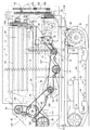
- the combine according to the embodiment includes a traveling machine body 1 supported by a pair of left and right iron crawler belts 2 as a traveling portion.
- a reaping device 3 for capturing uncut cereal grains such as rice (or wheat, soybeans or corn) is mounted by a single-acting lifting hydraulic cylinder 4 so as to be adjustable up and down. ing.
- a cab 5 as a driving part on which an operator gets on board is mounted.
- a Glen tank 6 for storing the grain after threshing is disposed behind the cab 5.
- An engine 7 as a power source is disposed behind the Glen tank 6.
- a grain discharge auger 8 is provided on the right side of the rear part of the Glen tank 6 so as to be able to turn.
- the grain in the Glen tank 6 is carried out, for example, to a truck bed, a container, or the like from the throat throw opening 8a at the tip of the discharge auger 8.
- a threshing device 9 for threshing the harvested cereal meal supplied from the harvesting device 3.
- a grain sorting mechanism 10 for performing swing sorting and wind sorting is arranged.
- the reaping device 3 includes a feeder house 11 that communicates with the handling port 9 a at the front of the threshing device 9, and a horizontally long bucket-like grain header 12 that is provided continuously at the front end of the feeder house 11.
- a scraping auger 13 is rotatably supported in the grain header 12.
- a take-up reel 14 with a tine bar is disposed above the front portion of the take-up auger 13.
- a clipper-shaped cutting blade 15 is disposed in front of the grain header 12.
- a weeding body 16 is provided on both the left and right sides of the front portion of the grain header 12.
- a supply conveyor 17 is provided in the feeder house 11.
- a beater 18 for passing cereals is provided between the feed end of the supply conveyor 17 and the handling port 9a.
- the lower surface part of the feeder house 11 and the front end part of the traveling machine body 1 are connected via the lifting hydraulic cylinder 4, and the reaping device 3 moves up and down by the lifting hydraulic cylinder 4.
- the tip side of the uncut grain culm between the left and right weed bodies 16 is scraped by the take-up reel 14, and the heel side of the uncut grain pod is cut by the cutting blade 15.
- the grain headers 12 are collected in the vicinity of the center of the left and right width.
- the whole amount of the harvested cereal grains of the grain header 12 is conveyed by the supply conveyor 17 and is input to the handling port 9 a of the threshing device 9 by the beater 18.
- the grain header 12 is provided with a horizontal control hydraulic cylinder 19 for rotating the grain header 12 about the horizontal control fulcrum shaft 19a, and the grain header 12,
- the cutting blade 15 and the take-up reel 14 are supported horizontally with respect to the field scene.
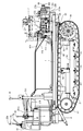
- a handling cylinder 21 is rotatably provided in a handling chamber of the threshing device 9.
- a handling cylinder 21 is pivotally supported on a handling cylinder shaft 20 extended in the front-rear direction of the traveling machine body 1.
- a receiving net 24 (concave) for allowing the grains to leak is stretched below the handling cylinder 21.
- a spiral (screw blade-shaped) intake blade 25 projects outward in the radial direction.
- the harvested cereal mash introduced from the handling port 9 a is kneaded between the handling cylinder 21 and the receiving net 24 while being conveyed toward the rear of the traveling machine body 1 by the rotation of the handling cylinder 21. Threshed.
- the threshing of grains or the like smaller than the mesh of the receiving net 24 leaks from the receiving net 24.
- the sawdust and the like that do not leak from the receiving net 24 are discharged from the dust outlet at the rear of the threshing device 9 to the field by the conveying action of the handling cylinder 21.
- a plurality of dust feeding valves (not shown) for adjusting the conveying speed of threshing in the handling chamber are pivotally mounted on the upper side of the handling cylinder 21 so as to be rotatable.
- the conveying speed (residence time) of threshing in the handling chamber can be adjusted according to the variety and properties of the harvested cereal.
- a rocking sorter 26 for specific gravity sorting having a grain pan, chaff sheave, grain sheave, Strollac and the like is provided as the grain sorting mechanism 10 disposed below the threshing device 9, a rocking sorter 26 for specific gravity sorting having a grain pan, chaff sheave, grain sheave, Strollac and the like is provided.
- the grain sorting mechanism 10 includes a tang fan 29 that supplies sorting wind.
- the threshing that has been threshed by the handling cylinder 21 and leaked from the receiving net 24 is the first of the grains (fine grains, etc.) by the specific gravity sorting action of the swing sorter 26 and the wind sorting of the Kara fan 29, Sorted into second crops such as grain with branch stems and sawdust.
- a first conveyor mechanism 30 and a second conveyor mechanism 31 are provided below the rocking sorter 26, as the grain sorting mechanism 10, a first conveyor mechanism 30 and a second conveyor mechanism 31 are provided below the rocking sorter 26, as the grain sorting mechanism 10, a first conveyor mechanism 30 and a second conveyor mechanism 31 are provided below the rocking sorter 26, as the grain sorting mechanism 10, a first conveyor mechanism 30 and a second conveyor mechanism 31 are provided below the rocking sorter 26, as the grain sorting mechanism 10, a first conveyor mechanism 30 and tang fan 29, the first item such as the grain dropped from the swing sorter 26 is collected in the glen tank 6 by the first conveyor mechanism 30 and the cereal conveyor 32.
- a second thing such as a grain with a branch is returned to the sorting start end side of the swing sorting board 26 via the second conveyor mechanism 31 and the second reduction conveyor 33 and is re-sorted by the swing sorting board 26.
- the sawdust and the like are discharged from the dust outlet 34 at the rear of the traveling machine body 1 to the field.
- the cab 5 is provided with a steering column 41 and a driver seat 42 on which an operator sits.
- left and right traveling speed change levers 43 and 44 as steering levers for changing the course of the traveling machine body 1 and changing the moving speed, and the reaping device 3 are moved up and down by tilting in the front-rear direction.
- a cutting posture lever 45 for raising and lowering the take-up reel 14 by tilting in the horizontal direction, an accelerator lever 46 for controlling the rotation of the engine 7, and a grain discharging lever 47 for operating the grain discharging auger 8. has been. As shown in FIG.
- the cutting clutch lever 39 (working clutch lever) for turning on and off the power transmission of the cutting device 3 and the power transmission of the threshing device 9 are turned on and off.
- a threshing clutch lever 40 (working clutch lever) to be operated is arranged.
- a brake pedal 38 for crawler belt 2 braking is provided below the front portion of the side column 41b.
- a roof 49 for awning is attached to the upper side of the cab 5 via a support column 48.
- the left and right track frames 50 are disposed on the lower surface side of the traveling machine body 1.
- the track frame 50 includes a drive sprocket 51 that transmits the power of the engine 7 to the crawler belt 2, a tension roller 52 that maintains the tension of the crawler belt 2, a plurality of track rollers 53 that hold the ground side of the crawler belt 2 in a grounded state, An intermediate roller 54 for holding the non-grounding side of the crawler belt 2 is provided.
- the rear side of the crawler belt 2 is supported by the drive sprocket 51, the front side of the crawler belt 2 is supported by the tension roller 23, the ground side of the crawler belt 2 is supported by the track roller 53, and the non-ground side of the crawler belt 2 is supported by the intermediate roller 54 To be configured.
- a bottom feed conveyor 60 disposed at the bottom of the Glen tank 6 and a vertical feed conveyor 61 disposed at the rear of the Glen tank 6 are provided.
- the left and right bottom feed conveyors 60 extend in the front-rear direction at the bottom of the grain tank 6 and convey the grains at the bottom of the grain tank 6 toward the lower end side of the vertical feed conveyor 61 provided vertically.
- the vertical feed conveyor 61 is extended in the vertical direction at the rear part of the grain tank 6, and conveys the grain from the upper end side of the vertical feed conveyor 61 toward the feed start end side of the grain discharge auger 8 on the right side of the grain tank 6. .
- the grain in the Glen tank 6 is conveyed to the throat throw port 8a at the tip of the discharge auger 8 (feed end side).
- the grain discharge auger 8 is supported on the upper end side of the vertical feed conveyor 61 so as to be rotatable up and down, and is configured so that the side of the grain discharge auger 8 that is the feed end side of the grain discharge auger 8 can be raised and lowered. Moreover, it is comprised so that the hull spout 8a side of the grain discharge auger 8 can be moved around the conveyor shaft center (horizontal direction) of the vertical feed conveyor 61. That is, the side of the heel throw 8a is moved to the lower side of the front part of the traveling machine body 1, and the grain discharge auger 8 is stored in the right side of the cab 5 and the grain tank 6 via the auger rest 8b.
- the side of the grain discharge auger 8 which is the feed terminal side, is raised, the side of the traveling machine body 1 is moved to the side or rear of the traveling machine body 1, and the side of the traveling machine body 1 is moved backward.
- the grain discharge auger 8 is protruded, and the grain thrower 8a is made to face the loading platform or container of the truck so that the grains in the grain tank 6 are carried out to the loading platform or container of the truck.
- the threshing device 9 includes a handling cylinder 21 for threshing threshing, a rocking sorter 26 for selecting a shed product falling below the handling cylinder 21, and a tang fan 29.
- the front side of the handling cylinder 21 faces the handling port 9a communicating with the feeder house 11, and the rear side of the handling cylinder 21 faces the dust outlet 34 at the rear of the threshing device 9. That is, the rear side of the handling cylinder 21 protrudes further rearward than the rear end of the receiving net 24 that causes the grains to leak.
- a dust exhaust port 34 is provided at the lower rear side of the handling cylinder 21 (an opening portion without the receiving net 24).
- the rotation axis of the handling cylinder 21 extends along the traveling direction (front-rear direction) of the traveling machine body 1.
- the threshed material threshed by the handling cylinder 21 by the inclined plate 119 is brought to the left and right center side of the swing sorter 26.
- the harvested cereal mash that has been introduced into the handling port 9 a of the threshing device through the feeder house 11 and the beater 18 from the reaping device 3 is threshed by the handling cylinder 21.
- the swing sorter 26 located below the receiving net 24 is configured to be able to swing back and forth in a diagonally forward and downward direction via a swing link 35.
- the swing sorter 26 includes a grain pan 36 located below the front portion of the receiving net 24, a movable chaff sheave 37 and a fixed chaff sheave 38 for adjusting the amount of grain leakage, and a movable chaff sheave 37 and the first conveyor mechanism 30. It has the arranged grain sheave 39 and the stroller rack 40 connected to the rear end side of the fixed chaff sheave 39.
- the cereals on the chaff sheaves 37 and 38 are subjected to specific gravity sorting by the chaff sheaves 37 and 38 themselves, and are separated into grains and sawdust by receiving a sorting wind flowing backward from the tang fan 29.
- Kernel (first thing) that has fallen from the movable chaff sheave 37 and the Glen sheave 39 is first collected by the conveyor mechanism 30 while removing the dust in the sorting air of the Kara fan 29.
- the grain taken out from the first conveyor mechanism 30 is carried into and collected in the Glen tank 6 through the cereal conveyor 32.
- the second object that has failed to pass through the movable chaff sheave 37 and the Glen sheave 39 and the second object that has dropped from the fixed chaff sheave 38 are collected by the second conveyor mechanism 31 that is the rearmost of the conveyor mechanism 30.
- the second items collected by the second conveyor mechanism 31 are returned to the upper surface side of the swing sorter 26 via the second reduction conveyor 33 and re-sorted.
- the relatively heavy sawdust on the chaff sheaves 37 and 38 is discharged from the dust outlet 34 to the outside of the machine via the stroller 40.
- a travel speed change pump case 66 having a pair of swash plate variable left and right travel hydraulic pumps 65 is provided.
- the engine 7 is mounted on the upper surface of the right rear portion of the traveling machine body 1, and the pump case 66 is disposed on the upper surface of the traveling machine body 1 on the left side of the engine 7.
- left and right reduction gear cases 63 are provided at the rear ends of the left and right track frames 50, respectively.
- a traveling hydraulic motor 69 is disposed in each of the left and right reduction gear cases 63.
- a travel drive input shaft 64 projecting rearward from the pump case 66 and an output shaft 67 projecting rearward from the engine 7 are connected via an engine output belt 231.
- the engine 7 and the pump case 66 are provided on the upper surface side of the traveling machine body 1 on the rear side of the threshing device 9, and the pump case 66 is disposed between the engine 7 and the threshing device 9.
- a charge pump 68 for driving the lifting hydraulic cylinder 4 and the like is also provided on the same axis 64 as the traveling hydraulic pump 65. Further, a working hydraulic pump 70 for operating the lifting hydraulic cylinder 4 or the horizontal control hydraulic cylinder 19 is disposed in the engine 7, and the charge pump 68 and the working hydraulic pump 70 are connected to the engine 7 in the same manner as the traveling hydraulic pump 65. It is comprised so that it may drive.
- the drive output of the engine 7 is transmitted to the left and right traveling hydraulic pump 65 via the output shaft 67.
- the left and right traveling hydraulic motors 69 are individually driven by the left and right traveling hydraulic pumps 65, and the left and right crawler belts 2 are moved forward and backward by the left and right traveling hydraulic motors 69. Further, the rotational speed of the left and right traveling hydraulic motor 69 is controlled, and the rotational speed of the left and right crawler belts 2 driven by the left and right traveling hydraulic motor 69 is varied to change the moving direction (traveling path) of the traveling machine body 1 and It is configured to perform direction changes on the ground.
- a pair of left and right traveling hydraulic motors 69 are hydraulically connected to the left and right traveling hydraulic pumps 65 via a closed loop hydraulic circuit.
- the left and right crawler belts 2 are driven in the forward direction or the reverse direction via the drive sprocket 51 by the left and right traveling hydraulic motor 69.
- the operator operates the left and right traveling speed change levers 43 and 44 to adjust the swash plate angles (shift control) of the left and right traveling hydraulic pumps 65, whereby the rotational speed or rotational direction of the left and right traveling hydraulic motors 69 can be adjusted.
- the left and right crawler belts 2 are driven independently from each other, and the traveling machine body 1 is configured to move forward or backward.
- a handling cylinder drive case 71 that supports a threshing input shaft 72 is provided.
- a threshing input shaft 72 is connected to the traveling drive input shaft 64 via a threshing drive belt 232.
- the power of the engine 7 is transmitted from the travel drive input shaft 64 to the threshing input shaft 72 via the threshing clutch 233 also serving as a tension roller and the threshing drive belt 232.
- the threshing clutch 233 is controlled to be turned on and off by the operator's lever operation.
- a threshing input shaft 72 is connected to one end side (rear end side) of the barrel 20 via a barrel drive belt 234.
- a cutting selection input case 73 is provided on the front wall of the threshing device 9.
- a cutting selection input shaft 74 is pivotally supported on the cutting selection input case 73.
- One end side (right end portion) of the cutting selection input shaft 74 is connected to the other end side (front end side) of the barrel 20 via a bevel gear 75.
- the other end side (left end portion) of the cutting selection input shaft 74 is connected to the left end portion of the beater shaft 82 on which the beater 18 is pivotally supported via the beater drive belt 238.
- the left end portion of the beater shaft 82 is connected to the left end portion of the hot shaft 76 supporting the hot fan 29 via a selection input belt 235.
- a tang shaft 76 is connected to the left end of the first conveyor shaft 77 of the first conveyor mechanism 30 and the left end of the second conveyor shaft 78 of the second conveyor mechanism 31 via a conveyor drive belt 237.
- a left end portion of a second conveyor shaft 78 is connected to a left end portion of a crank-like swing drive shaft 79 pivotally supported by the rear portion of the swing sorting plate 26 via a swing sorting belt 236.
- the cereal conveyor 32 is driven via the first conveyor shaft 77, and the first selected grain of the first conveyor mechanism 30 is collected in the Glen tank 6.
- the second reduction conveyor 33 is driven via the second conveyor shaft 78, and the second selected grain mixed with the sawdust from the second conveyor mechanism 31 is returned to the upper surface side of the rocking sorter 26.
- the combination of the sorting input belt 235, the swing sorting belt 236, and the conveyor drive belt 237 corresponds to a sorting drive belt for transmitting power to the grain sorting mechanism 10.
- the left end portion of the cutting input shaft 89 on which the feed end side of the supply conveyor 17 is pivotally supported is connected to the left end portion of the beater shaft 82 via a cutting drive belt 241 and a cutting clutch 242.
- the right end of the cutting input shaft 89 is connected to the header drive shaft 91 provided on the grain header 12 via the header drive chain 90.
- a header drive shaft 91 is connected to a drive shaft 93 that supports the drive auger 13 via a drive drive chain 92.
- a header drive shaft 91 is coupled to a reel shaft 94 that supports the take-up reel 14 via an intermediate shaft 95 and reel drive chains 96 and 97.
- the cutting blade 15 is connected to the right end portion of the header driving shaft 91 through a cutting blade driving crank mechanism 98.
- the feed conveyor 17, the auger 13, the hoisting reel 14, and the cutting blade 15 are driven and controlled so as to continuously mow the tip of the uncut grain culm in the field. It is configured.
- a reaping device 3 a threshing device 9 having a handling cylinder 21, and a traveling machine body 1 having a driver's seat 42 are provided.
- the engine 7 is mounted on the rear part of the traveling machine body 1, and the power of the engine 7 is transmitted to the rear end side of the handling cylinder 20 on which the handling cylinder 21 is pivotally supported.
- the power of the engine 7 is transmitted from the front end side of the handling cylinder shaft 20 to the cutting device 3 and the beater 18, the beater 18 is driven via the handling cylinder shaft 20, and the cutting device 3 is driven via the beater 18.
- the large reaping device 3 having a wide cutting width can be stably supported, and the front-rear balance of the traveling machine body 1 can be improved. That is, it is possible to improve harvesting workability in wet fields or mobility on rough roads. Further, since the power of the engine 7 is transmitted to the beater 18 and the reaping device 3 using the handling cylinder 20, even if the reaping device 3 and the engine 7 are provided apart from each other, the engine 7 is connected to the beater 18 or the reaping device 3.
- the transmission path can be easily configured. That is, the maintenance workability of the drive structure such as the reaping device 3 or the threshing device 9 can be improved.
- the rear end side of the bottom feed conveyor shaft 103 of the bottom feed conveyor 60 is connected to the rear end portion of the travel drive input shaft 64 via the grain discharge belt 244 and the grain discharge clutch 245.
- One end side of the lower mediation shaft 105 is connected to the rear end portion of the bottom feed conveyor shaft 103 via a longitudinal feed drive chain 104.
- the other end side of the mediation shaft 105 is connected to the lower end side of the vertical feed conveyor shaft 106 of the vertical feed conveyor 61 via a bevel gear mechanism 107.
- One end side of the upper intermediate shaft 109 is connected to the upper end side of the vertical feed conveyor shaft 106 via a bevel gear mechanism 108.
- One end side of the grain discharge shaft 111 is connected to the other end side of the upper mediation shaft 109 via the grain discharge drive chain 110.
- the feed start end side of the discharge auger shaft 112 of the grain discharge auger 8 is connected to the other end side of the grain discharge shaft 111 via a bevel gear mechanism 113.
- front and rear grain discharge ports 221 and 222 are provided at the bottom of the Glen tank 6.
- the wrinkle receiving base 223 is arrange
- An operator other than the operator of the driver's seat 42 rides on the saddle cradle 223 in a state where the saddle cradle 223 is supported in a horizontal working posture, and attaches a saddle bag to a saddle catcher (not shown).
- the grain in the Glen tank 6 is discharged into the bag.
- the straw bag filled with the grain is dropped from the straw catcher 223 to the field and collected.
- the grains in the grain tank 6 can be discharged without interrupting the mowing and threshing operation. That is, compared with the work of discharging the grain in the grain tank 6 from the grain discharge auger 8, there is almost no need to interrupt the mowing and threshing work. Work efficiency can be improved.
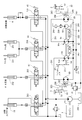
- the combine hydraulic structure and the travel drive structure will be described with reference to FIGS.
- the hydraulic actuator the harvesting lifting hydraulic cylinder 4, the horizontal control hydraulic cylinder 19, the left and right reel lifting hydraulic cylinders 251 that support the take-up reel 14 so as to be lifted and lowered, and the grain
- An auger lifting / lowering hydraulic cylinder 252 that supports the discharge auger 8 to be movable up and down is provided.
- the working hydraulic pump 70 is hydraulically connected to the horizontal control hydraulic cylinder 19 through a horizontal control electromagnetic hydraulic valve 253 that is controlled by operation of the horizontal control switch 254.
- the horizontal control switch 254 When the operator operates the horizontal control switch 254 to operate the horizontal control hydraulic cylinder 19, the left-right inclination of the traveling machine body 1 is maintained at a horizontal or arbitrary inclination.
- a horizontal control switch is provided at the upper end of the cutting posture lever 45.
- the working hydraulic pump 70 is hydraulically connected to the cutting lift hydraulic cylinder 4 via the cutting lift manual hydraulic valve 255.
- the cutting lifting / lowering hydraulic cylinder 4 is actuated so that the operator moves the cutting device 3 up and down to an arbitrary height (for example, cutting height or non-working height). It is configured.
- the working hydraulic pump 70 is hydraulically connected to the reel lifting hydraulic cylinder 251 through the reel lifting manual hydraulic valve 256.
- the reel lifting hydraulic cylinder 251 is actuated, and the operator lifts and lowers the take-up reel 14 to an arbitrary height to harvest the uncut grain culm on the field. .
- the working hydraulic pump 70 is hydraulically connected to the auger lifting hydraulic cylinder 252 via the auger lifting manual hydraulic valve 257.
- the auger lifting / lowering hydraulic cylinder 252 is operated, and the operator moves the cocoon throwing port 8a of the grain discharging auger 8 up and down to an arbitrary height.
- the grain discharge auger 8 is rotated in the horizontal direction by an electric motor (not shown), and the cocoon throwing port 8a is moved in the horizontal direction.
- the culling spout 8a is positioned above the truck bed or container, and the grains in the grain tank 6 are discharged into the truck bed or container.
- left and right traveling hydraulic motors 69 are hydraulically connected to the left and right traveling hydraulic pumps 65 via left and right closed hydraulic circuits 261, respectively.
- the left and right traveling speed change levers 43 and 44 are connected to the output adjustment swash plate 65a of the left and right traveling hydraulic pump 65 via the servo valve mechanism 262, respectively, so that the left and right traveling speed change levers 43 and 44 are inclined in the front-rear direction.
- the support angle of the output adjustment swash plate 65a is changed proportionally.
- the left and right traveling hydraulic motors 69 are respectively driven by the left and right traveling hydraulic pumps 65, and the driving force of the left and right traveling hydraulic motors 69 is transmitted to the left and right crawler belts 2 via the reduction gear mechanism 263 of the reduction gear case 63, respectively.
- the left and right crawler belts 2 are driven forward or backward.
- the traveling body 1 can move straight in the forward direction at a vehicle speed proportional to the inclination angle of the left and right traveling speed change levers 43 and 44.
- the vehicle can move straight in the backward (reverse) direction at a vehicle speed proportional to the tilt angle of the left and right traveling speed change levers 43 and 44.
- the left and right traveling speed change levers 43 and 44 have different inclination angles to the front of the machine
- the left and right traveling speed change levers 43 and 44 have different inclination angles to the rear of the machine, or the left and right traveling speed change levers.
- the left and right traveling speed change levers 43 and 44 are inclined at a vehicle speed proportional to the inclination angle of the left and right traveling speed change levers 43 and 44.
- the traveling machine body 1 can be turned in the left-right direction with a turning radius proportional to the angle difference.
- a left and right closed hydraulic circuit 261 is connected to the high pressure oil discharge side of the charge pump 68 via an oil cooler 264 and a line filter 265 so that the hydraulic oil in the oil tank 266 is supplied to the left and right closed hydraulic circuits 261. It is configured.
- An oil tank 266 is mounted on the upper surface of the traveling machine body 1 on the left side of the fuel tank 267 of the engine 7, and the driver's seat 42 is disposed above the fuel tank 267 via a seat frame 268.
- the pump case 66 in which the left and right traveling hydraulic pumps 65 are built is mounted on the engine 7 mounted on the right upper surface of the rear portion of the traveling machine body 1 and on the left upper surface of the traveling machine body 1.
- the threshing device 9 is fixed to the upper surface side of the traveling machine body 1 via the front support body 271 and the rear support body 272 between the right side wall body of the threshing device 9.
- a U-shaped intermediate portion of the front support body 271 is fastened to the upper surface of the traveling machine body 1 with bolts 273.
- the left and right sides of the pump case 66 are fastened with bolts 274 to both U-shaped ends of the front support 271. That is, the front part of the pump case 66 in which the charge pump 68 is disposed is supported by the traveling machine body 1 by the front support body 271.
- the bottom surface side of the rear support body 272 is fastened to the mounting base 275 on the upper surface side of the traveling machine body 1 with bolts 276.
- the rear side of the pump case 66 is fastened to the front side of the rear support 272 with bolts 277.
- a support arm body 272a extends rearward from the rear surface of the rear support body 272, and the lower end side of the rear bearing body 278 is fastened to the rear end portion of the support arm body 272a with a bolt 279.
- the rear end side of the travel drive input shaft 64 protrudes rearward from the rear surface of the pump case 66, and the travel drive input shaft 64 is passed through the rear support body 272 and the rear bearing body 278.
- a grain discharge drive pulley 282 around which the grain discharge belt 244 is wound is pivotally supported at the rear end portion of the travel drive input shaft 64 protruding rearward from the rear bearing body 278. That is, an engine output transmission pulley 280, a threshing output transmission pulley 281 and a grain discharge driving pulley 282 as counter pulleys are pivotally supported on a travel drive input shaft 64 as a counter shaft.
- an engine output pulley 283 is pivotally supported on the output shaft 67 of the engine 7, and the engine output belt 231 is wound between the engine output transmission pulley 280 and the engine output pulley 283.
- a large-diameter threshing input pulley 284 is pivotally supported on one end side of the threshing input shaft 72, and a threshing driving belt 232 is wound between the threshing output transmission pulley 281 and the large-diameter side threshing input pulley 284.
- a small-diameter threshing input pulley 285 is pivotally supported on the other end side of the threshing input shaft 72, and a barrel driving belt 234 is disposed between the barrel input pulley 286 on the barrel shaft 20 and the small-diameter threshing input pulley 285. Wrap around. Further, a grain discharge pulley 287 is pivotally supported on the rear end side of the bottom feed conveyor shaft 103, and a grain discharge belt 244 is wound between the grain discharge drive pulley 282 and the grain discharge pulley 287.
- the driving force output from the engine 7 is branched and transmitted by the travel drive input shaft 64 as a counter shaft. That is, the output of the engine 7 is transmitted from the travel drive input shaft 64 to the left and right travel hydraulic pumps 65. Further, the output of the engine 7 is transmitted from the threshing output transmission pulley 281 on the traveling drive input shaft 64 to the barrel shaft 20 of the threshing device 9 via the threshing drive belt 232 and the barrel driving belt 234. On the other hand, the output of the engine 7 is transmitted from the grain discharge drive pulley 282 on the travel drive input shaft 64 to the grain discharge auger 8 via the grain discharge belt 244.
- the engine 7 is mounted on the rear portion of the traveling machine body 1
- the threshing device 9 and the grain tank 6 are provided on the traveling machine body 1
- the reaping device is disposed in front of the threshing device 9.
- a travel drive input shaft 64 as a counter shaft parallel to the output shaft 67 of the engine 7 and at the same height position, an engine output pulley 283 on the output shaft 67, and a counter on the counter shaft 64 Since the engine output transmission pulley 280 or the threshing output transmission pulley 281 or the grain discharge drive pulley 282 as the pulley and the threshing input pulley 284 of the threshing device 9 are arranged flush with the rear surface of the traveling machine body 1, the engine 7 for compactly assembling the threshing drive belt 232 or the like for transmitting power from the threshing device 7 to the rear surface side of the engine 7 or the rear surface side of the threshing device 9 Kill.
- the engine output transmission pulley 280 on which the output belt 231 of the engine 7 is suspended can be disposed at a position where vibration of the engine 7 is reduced. Further, by opening the rear portion of the traveling machine body 1, replacement or maintenance work of the output belt 231 of the engine 7 or the threshing driving belt 232 of the threshing device 9 can be easily performed from the rear side of the traveling machine body 1. That is, the handling workability can be improved while the power transmission structure of the engine 7 can be simplified.
- the left and right traveling hydraulic pumps 65 and the left and right traveling hydraulic motors 69 are provided, and the left and right traveling hydraulic motors 69 are operated by the left and right traveling hydraulic pumps 65. Since the left and right traveling hydraulic pumps 65 are disposed on the traveling drive input shaft 64, the traveling hydraulic pump 65 can be installed compactly in the engine room adjacent to the engine 7. Further, the traveling hydraulic pump 65 can be easily air-cooled by the cooling air of the engine 7. The driving efficiency of the crawler belt 2 can be improved while the hydraulic piping structure of the left and right traveling hydraulic pumps 65 and the left and right traveling hydraulic motors 69 can be simplified.
- the engine 7 is mounted on the traveling machine body 1 below the rear part of the Glen tank 6, and the grain discharge pulley 287 of the Glen tank 6 is attached to the rear surface of the traveling machine body 1.
- , 281, 282 are arranged flush with each other, so that the rear part of the traveling machine body 1 is opened, so that the grain discharge belt 244 of the grain tank 6 can be replaced or maintained from the rear side of the traveling machine body 1. Easy to execute. While the power transmission structure to the Glen tank 6 can be simplified, handling workability can be improved.
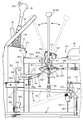
- a beater 18 and a beater shaft 82 for passing cereals are arranged below a cutting selection input shaft 74 that protrudes leftward and rightward from the cutting selection input case 73 at the front of the threshing device 9. Yes.
- Power is transmitted from the cutting selection input shaft 74 to the beater shaft 82 via the beater drive belt 238.
- the power transmitted to the beater shaft 82 is distributed by being distributed back and forth on the left wall side of the threshing device 9 toward the reaping device 3 and the grain sorting mechanism 10.
- power is transmitted from the beater shaft 82 to the cutting input shaft 89 that pivotally supports the feed end side of the supply conveyor 17 via the cutting drive belt 241 and the cutting clutch 242, and to the cut shaft through the selection input belt 235. Power is transmitted to 76.
- the cutting input shaft 89 and the tang shaft 76 are located further below the beater shaft 82.
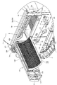
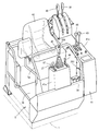
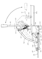
- the outer surface side of the left wall in the threshing device 9 is covered with a total of four cover bodies 121 to 124 arranged vertically and front and back.
- These cover bodies 121 to 124 are basically for protecting the movable parts (pulleys, belts, etc.) on the left side of the combine.
- the lower front cover body 123 covers and conceals the movable parts of the cutting input shaft 89 and the red pepper shaft 76, and the lower rear cover body 124 conceals the movable parts behind the red pepper shaft 76 in the grain sorting mechanism 10.
- the upper front cover body 121 covers the movable parts of the cutting and sorting input shaft 74 and the beater shaft 82, and the upper rear cover body 122 as a lateral plate covers the left side portion of the handling cylinder 21.
- the lower front and rear cover bodies 123 and 124 and the upper front cover body 121 are detachably mounted on the outer surface side of the left side wall body in the threshing device 9.
- the upper rear cover body 122 is provided so as to be able to open and close in the horizontal direction with the vertical axis 125 on the front side as a rotation fulcrum. That is, the pair of upper and lower horizontal frames 126 that are strength members of the upper rear cover body 122 has a front end side protruding from the front end surface of the upper rear cover body 122.
- the projecting end portions of the horizontal frames 126 are pivotally mounted on the vertical axis 125 at two upper and lower support stay portions 127 provided on the front outer surface side of the left wall.
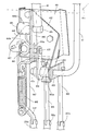
- a rectangular opening 128 is formed on the upper side of the left wall of the threshing device 9 so that the handling cylinder 21 can face.
- the rectangular opening 128 of the threshing device 9 is closed, and if the upper rear cover body 122 is opened, the handling cylinder 21 and the right receiving net 24b facing the rectangular opening 128 (details) Will be exposed later).
- the movable part of the cutting selection input shaft 74 and the beater shaft 82, the movable part of the cutting input shaft 89, and the movable part of the grain sorting mechanism 10 are arranged around the upper rear cover body 122. And is provided so as to bypass the upper rear cover body 122. Therefore, although both the movable parts and the upper rear cover body 122 are on the left wall side of the threshing device 9, the opening and closing rotation around the vertical axis 125 of the upper rear cover body 122 interferes with the movable parts. Absent.
- the receiving network 24 of the embodiment is a concave type formed in a lattice shape, and is configured by a combination of a pair of receiving network portions 24a and 24b that can be divided in the left-right direction.
- the right receiving net portion 24b near the right wall of the threshing device 9 is fixed to the front wall, the right wall, and the like of the threshing device 9.
- the left receiving mesh portion 24 a located near the upper rear cover body 122 is fixed to the inner surface side of the upper rear cover body 122 so as to rotate integrally with the upper rear cover body 122.
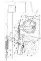
- a front and rear longitudinal locking pin body 129 is provided on the outer surface side of the rear wall body in the threshing device 9.
- a hook lever 130 that is detachably hooked and engaged with the locking pin body 129 on the rear wall body side is provided so as to be rotatable.
- the hook lever 130 is always biased by a tension spring 131 in a direction in which the hook lever 130 is hooked and engaged with the locking pin body 129.
- An operation hole 132 through which the handle shaft portion of the hook lever 130 passes is provided on the rear side of the upper rear cover body 122.
- the upper front cover body 121 When opening the upper rear cover body 122, the upper front cover body 121 is removed in advance, and then the hook lever 130 is rotated in the disengagement direction to open and rotate the upper rear cover body 122 leftward. You can do it. Then, the upper rear cover body 122 rotates around the vertical axis together with the left receiving mesh portion 24a, and the handling cylinder 21 and the right receiving mesh portion 24b in the threshing device 9 are exposed. When closing the upper rear cover body 122, it is only necessary to push the free end side of the upper rear cover body 122 toward the threshing device and to close and rotate it in the right direction.
- the cutting device 3 including the cutting blade 15 and the threshing device 9 including the handling cylinder 21 and the receiving net 24 are provided, and the threshing device 9 is connected to the threshing device 9 via the feeder house 11 and the beater 18. It is a normal combine that supplies the harvested cereal rice cake, and a grain tank 6 is arranged on one side of the left and right sides of the threshing device 9, and the left and right other sides of the threshing device 9 are opened and closed around a vertical axis 125.
- a possible lateral side plate 122 is provided, and the handling cylinder 21 and the receiving net 24 in the threshing device 9 are exposed by opening and turning the lateral side plate 122, so that the mounting height of the lateral side plate 122 is almost changed. Without this, the lateral plate 122 can be opened and closed. For this reason, it is easy to open and close the lateral side plate 122 regardless of the height of the operator, and there is no inconvenience of the opening and closing operation as in the prior art. Further, since the lateral plate 122 is configured to open / close and rotate around the vertical axis 125, that is, to rotate horizontally, the lateral plate 122 is opened even without an actuator such as a gas cylinder as in the prior art. Can be maintained. For this reason, it is not necessary to secure the space for arranging the actuator, the number of parts can be reduced, and the manufacturing cost can be reduced.
- the receiving net 24 is configured by a combination of a pair of receiving net parts 24 a and 24 b that can be divided in the left-right direction, and the left receiving net part 24 a near the lateral side plate 122 rotates integrally with the lateral side plate 122.
- the left receiving mesh portion 24a is also opened and rotated around the longitudinal axis 125 together with the lateral side plate 122. become. For this reason, the side space around the handling cylinder 21 and the receiving net 24 in the threshing device 9 can be greatly opened, and cleaning work and maintenance work are easy to perform.
- a grain selection mechanism 10 is provided below the lateral plate 122 in the threshing device 9, and the beater 18 is disposed between the feeder house 11 and the threshing device 9.
- the power of the engine 7 that is disposed below the front end side of the front and rear longitudinal barrel shaft 20 that pivotally supports and is mounted on the rear portion of the traveling machine body 1 is transmitted to the beater 18 via the barrel shaft 20,
- the power transmitted to the beater 18 is distributed and distributed back and forth on the other side of the threshing device 9 toward the reaping device 3 and the grain sorting mechanism 10.
- both the power transmission system to the grain sorting mechanism 10 and the lateral plate 122 are on the other side of the threshing device 9, the power transmission system to the reaping device 3 and the grain sorting mechanism 10 is provided. Bypassing the side plate 122 It is is will be. For this reason, both the maintenance work of the handling cylinder 21 and the receiving net 24 and the maintenance work for the power transmission system to the harvesting device 3 and the grain sorting mechanism 10 are performed from the opposite side of the Glen tank 6 installation side. It can be executed easily and maintenance workability is improved.
- a pedal frame 275 is erected from the cab 5 and the base end portion of the brake pedal 38 is pivotally supported on the pedal frame 275 via a pedal fulcrum shaft 276.
- One end side of the brake wire 278 is connected to the base end portion of the brake pedal 38 via the wire arm 277.
- a pedal return spring 280 is connected to the base end portion of the brake pedal 38 via a spring arm 279. The pedal return spring 280 is configured to support the stepping portion 38a of the brake pedal 38 at the raised position.
- the side column frame 281 forming the side column 41b includes an upper frame 281a that extends horizontally in the front-rear direction, a front column 281b that supports the front end portion of the upper frame 281a, It has an auxiliary column 281c erected in parallel with the front side of the column 281b, and an auxiliary upper frame 281d that connects the upper end of the column 281c to the front column 281b.
- the brake pedal 38 comes into contact with the lower surface of the auxiliary upper frame 281d, and the brake pedal 38 is supported at the raised position by the pedal return spring 280.
- the parking lever 283 is rotatably supported by the auxiliary column 281c and the auxiliary upper frame 281d via the upper and lower brackets 282.
- the pedal hook body 283a of the parking lever 283 is locked to the brake pedal 38, and the brake pedal is resisted against the pedal return spring 280.
- 38 is configured to be supported in a downward movement (braking) position.
- a release spring 284 for supporting the parking lever 283 is provided at a position where the pedal hook body 283a is not locked to the brake pedal 38.
- the brake wire 278 is provided with a brake link 286 that connects the upper end side via a brake spring 285.
- An intermediate portion of the brake link 286 is pivotally supported on the traveling machine body 1 via a link support shaft 287.
- a lower end side of the brake link 286 is connected to a brake braking lever 296 provided in the left traveling hydraulic motor 69 via a pin shaft body 288 and a long hole 289.
- a brake brake lever 296 provided on the right traveling hydraulic motor 69 is connected to the pin shaft body 288 via a bolt shaft body 290 and a connection shaft body 291 whose connection length can be adjusted.
- a lever return stopper body 292 that supports the brake brake lever 296 at the brake release position, and a brake release spring 293 that supports the brake brake lever 296 in contact with the lever return stopper body 292 are provided.
- a lever return stopper body 292 is provided on the left traveling hydraulic motor 69, and a brake release spring 293 is connected between the brake braking lever 296 provided on the left traveling hydraulic motor 69 and the lever return stopper body 292.
- a shift lever fulcrum shaft 411 that pivotally supports the left and right traveling shift levers 43 and 44 so as to be pivotable in the front-rear direction on the upper frame 281a of the side column frame 281 forming the side column 41b.
- the shift lever fulcrum shaft 411 is passed through the upper frame 281a, and the middle portion of the shift lever fulcrum shaft 411 is fixed to the upper frame 281a.
- the base end portions of the left and right traveling shift levers 43 and 44 and the middle portions of the left and right lever operation plates 412 and 413 are rotated to the left and right ends of the shift lever fulcrum shaft 411 protruding in the left-right direction from the upper frame 281a.
- the left shift lever 43 and the left lever operation plate 412 are fixed together.
- the right travel shift lever 44 and the right lever operation plate 413 are integrally fixed.
- the left shift lever 43 (left lever operation plate 412) and the right shift lever 44 (right lever operation plate 413) are supported by the shift lever fulcrum shaft 411 so as to rotate independently. Yes.
- interlocking detent ball mechanism 414 that removably connects the left and right lever operation plates 412 and 413, the upper end sides of the left and right lever operation plates 412 and 413 are engaged by the interlocking detent ball mechanism 414, When either one of the left and right traveling speed change levers 43 and 44 is operated, the other is operated in conjunction with an operation load equal to or less than the engaging force of the interlocking detent ball mechanism 414. When the operation load is greater than the engaging force of the interlocking detent ball mechanism 414, only one traveling speed change lever 43 or 44 on the side where the operation is performed is operated.
- one end sides of the left and right shift push-pull wires 415 and 416 are connected to the lower end sides of the left and right lever operation plates 412 and 413 via the left and right wire connecting shaft bodies 419a and 419b, respectively.
- the other end sides of the left and right shift push-pull wires 415 and 416 are connected to a servo valve mechanism 262 for switching the output adjusting swash plate 65a.
- Either one or both of the left and right traveling hydraulic pumps 65 are controlled to rotate forward by tilting the front of either one or both of the left and right traveling shift levers 43 and 44, and either one or both of the left and right crawler belts 2 are controlled. Is driven forward.
- one or both of the left and right traveling hydraulic pumps 65 are reversely controlled by a tilting operation to the rear side of either one or both of the left and right traveling speed change levers 43, 44, and either one of the left and right crawler belts 2 or Both are driven backwards.
- the course of the traveling machine body 1 is changed by changing the amount of tilting operation of the left and right traveling speed change levers 43 and 44, and turning (U-turn) or the like on the field headland is executed.
- Left and right neutral detent ball mechanisms 417 and 418 detachably connected to the engagement notches 412a and 413a of the left and right lever operation plates 412 and 413 are provided.
- Left and right neutral detent ball mechanisms 417 and 418 are provided on both sides of the upper frame 281a.
- a switch base 421 provided on the front column 281b, a reverse switch 422 provided on the switch base 421, and a reverse sensor arm 423 for operating the switch arm 422a of the reverse switch 422 are provided.
- a reverse sensor arm 423 is provided on the switch base 421.
- reverse operation arms 424 are provided on the left and right lever operation plates 412 and 413, respectively. When either one or both of the left and right speed change levers 43 and 44 are operated in reverse, the reverse operation arm 424 is brought into contact with the reverse sensor arm 423 and the reverse switch 422 is operated to notify the reverse operation. ing.
- a pair of clamping plate bodies 427 for simultaneously clamping the left and right wire connecting shaft bodies 419a and 419b is provided.
- One end side of a pair of sandwiching plate bodies 427 is rotatably connected to the upper frame 281a via a pivoting plate body 428.
- One end side of the pair of tension links 429 is connected to the other end side of the pair of sandwiching plate bodies 427, respectively.
- One end of a tension rod 430 whose length is adjustable is connected to the other end of the pair of tension links 429.
- the pedal arm portion of the brake pedal 38 is connected to the other end side of the tension rod 430.
- the reaping device 3, the threshing device 9 having a handling cylinder 21, and the traveling machine body 1 having a driver's seat 42 are provided, and cereals are supplied from the reaping device 3 to the threshing device 9.
- the harvesting posture lever 45 is provided as a harvesting operation lever in the steering column 41 in front of the driver seat 42 and the left and right traveling speed change levers 43 and 44 are provided in the steering column 41 on the side of the driver seat 42.
- the left and right traveling units 2 can be controlled by operating the shift levers 43 and 44, respectively.
- the operator sitting on the driver's seat 42 can switch the left and right traveling shift levers 43 and 44 by left hand operation, and the cutting posture lever 45 can be switched by the right hand operation of the operator, thereby improving the maneuverability.
- the operator can operate the cutting posture lever 45 with the right hand to move the take-up reel 14 up and down while raising and lowering the cutting device 3, while the operator moves the left and right with the left hand.
- the vehicle speed (movement speed) can be changed by a speed change operation while operating the travel speed change levers 43 and 44 and changing the course by a left and right turning operation.
- the cutting posture operation of the cutting device 3 provided with the take-in reel 14 or the like can be simplified. It is possible to improve the cutting workability in a field that requires a vehicle speed (moving speed) change operation or a course change operation, such as a field where grain cereals are partially lying down.
- a cutting machine 3 As shown in FIGS. 1, 5, 8, and 18 to 21, a cutting machine 3, a threshing device 9 having a handling cylinder 21, and a traveling machine body 1 having a crawler belt 2 as left and right traveling units are provided.
- the combine that supplies the cereal meal from the device 3 to the threshing device 9 has a structure in which a reduction gear case 63 as a left and right reduction case for independently driving the left and right crawler belts 2 is provided. Since the brake mechanisms 297 are respectively arranged and the left and right brake mechanisms 297 are connected to the brake pedal 38 as a single brake operating tool of the cab 5 as the driving operation unit, the left and right brake mechanisms 297 are operated by operating the brake pedal 38.
- the brake mechanism 297 can be operated simultaneously, and the left and right crawler belts 2 can be braked simultaneously.
- the traveling machine body 1 can be stopped without changing the moving direction (the course) of the traveling machine body 1. Further, for example, even if the brake pedal 38 and the left and right brake mechanisms 297 are installed separately from the front and rear parts of the traveling machine body 1, the braking operation structure of the left and right crawler belts 2 can be reduced in cost. It can be configured simply.
- the left and right traveling hydraulic motors 69 provided in the left and right reduction gear cases 63 are arranged with their installation positions shifted in the front-rear direction of the traveling machine body 1.
- a brake link 286 as a brake lever is provided in the traveling machine body 1 located in the middle, and a brake pedal as a brake operation tool is provided via a brake link 286 to the left and right brake mechanisms 297 provided on the left and right traveling hydraulic motor 69 axes.
- the left and right traveling hydraulic motors 69 can be disposed close to each other in the left-right width direction of the traveling machine body 1, and a traveling unit braking operation structure for coupling the brake pedal 38 to the left and right brake mechanisms 297 is provided. It can be configured at low cost and simply.
- the brake pedal 38 at the front part of the traveling machine body 1 and the left and right brake mechanisms 297 at the rear part of the traveling machine body 1 can be easily connected by a single brake wire 278 that brakes the left and right brake mechanisms 297.
- the braking force of the brake mechanism 297 can be easily adjusted, and the maintenance workability can be improved.
- the left and right traveling speed change levers 43 and 44 are provided on the cab 5, and the left and right traveling speed change levers 43 and 44 are operated by stepping on the brake pedal 38 as a brake operating tool.
- the left and right crawler belts 2 can be braked by setting the travel shift to neutral (running drive output is zero) only by the braking operation of the brake pedal 38. It is possible to prevent the traveling hydraulic pump 65 or the traveling hydraulic motor 69 from being overloaded by eliminating the difference between the timing for returning the left and right traveling shift levers 43 and 44 to the neutral position and the timing for braking the left and right crawler belts 2.
- the hydraulic structure for driving the crawler belt 2 incorporating the traveling hydraulic pump 65 or the traveling hydraulic motor 69, or the operation for stopping the left and right crawler belts 2 and the like. That is, while the manufacturing cost of the hydraulic structure for driving the crawler belt 2 can be easily reduced, handling operability such as maintenance of the hydraulic structure for driving the crawler belt 2 can be improved. Further, an emergency stop can be performed by omitting the neutral return operation of the left and right traveling speed change levers 43 and 44, and the slippage of the crawler belt 2 or the excavation of a farm scene can be reduced.
- a lever fulcrum chassis 441 is fixed to the inner surface of the front column 41 a that is erected from the cab 5.
- the lever fulcrum frame 442 is bolted to the lever fulcrum chassis 441.
- a left / right rotation fulcrum shaft 443 is fixed to the lever fulcrum frame 442.
- a left-right rotation frame 444 is provided that is supported to be rotatable about a left-right rotation fulcrum shaft 443 extending in the front-rear direction of the machine body.
- the left and right rotation boss 444a and the front and rear rotation boss 444b are integrally fixed to the left and right rotation frame 444.
- left and right rotation boss 444a is pivotally supported on the left and right rotation fulcrum shaft 443.
- a front / rear rotation fulcrum shaft 445 is pivotally supported on the front / rear rotation boss 444b.
- a base end portion of the cutting posture lever 45 and an upper end portion of the front / rear rotation frame 446 are integrally fixed to a front / rear rotation fulcrum shaft 445 extending in the left-right direction of the machine body.
- a fulcrum side frame 453 for fixing one end side to the lever fulcrum frame 442 is provided as shown in FIGS.
- the lever fulcrum boss portion 453a is integrally fixed to the fulcrum side frame 453.
- the base end portion 47a of the grain discharge lever 47 is passed through the fulcrum side frame 453 and the lever fulcrum boss portion 453a, and the grain discharge lever 47 is pivotally supported by the lever fulcrum boss portion 453a so as to be rotatable in the front-rear direction.
- An intermediate portion of an L-shaped cutting lift link 454 is rotatably supported on the base end portion 47 a of the grain discharge lever 47.
- a vertically long locking groove 446 a is formed on the lower end side of the front / rear rotating frame 446.
- An engagement shaft body 455 is provided on one end side of the L shape of the cutting lift link 454, and the engagement shaft body 455 is slidably engaged in the locking groove 446a.
- the upper end side of the plate-shaped cutting rod lifting / lowering cooperative rod body 456 is connected to the L-shaped other end side of the cutting lifting link 454.
- the lower end side of the cutting / lifting cooperation rod body 456 is connected to the cutting lifting / lowering spool 255a of the manual lifting / lowering hydraulic valve 255.
- the cutting lifting link 454 is moved around the base end portion 47a of the grain discharge lever 47.
- the upper end side of the plate-shaped reel ascending / descending cooperation rod body 458 is connected to the left / right rotation frame 444 via the pivot shaft 457.
- the lower end side of the reel lifting / lowering cooperative rod body 458 is connected to the reel lifting / lowering spool 256a of the reel lifting / lowering manual hydraulic valve 256. That is, by turning the cutting posture lever 45 about the left and right rotation fulcrum shaft 443 and tilting the cutting posture lever 45 in the left and right direction of the machine body, the left and right rotation frame 444 rotates about the left and right rotation fulcrum shaft 443.
- the reel raising / lowering linkage rod body 458 is moved up and down, the reel raising / lowering spool 256a is operated, the reel raising / lowering manual hydraulic valve 256 is switched, the reel raising / lowering hydraulic cylinder 251 is operated, and the take-up reel 14 is moved up and down. It is configured to make it.
- the grain discharge link 459 is fixed to the base end portion 47a of the grain discharge lever 47.
- the upper end side of the plate-shaped conveyor lifting / lowering cooperation rod body 460 is connected to the grain discharge link 459.
- the lower end side of the conveyor lifting / lowering cooperation rod body 460 is connected to the auger lifting / lowering spool 257a of the auger lifting / lowering manual hydraulic valve 257. That is, by turning the grain discharge lever 47 around the axis of the base end 47a and tilting the grain discharge lever 47 in the longitudinal direction of the machine body, the grain discharge link 459 is turned and the conveyor lifting / lowering cooperation is performed.
- the rod body 460 is moved up and down to operate the auger lifting and lowering spool 257a, to switch the auger lifting and lowering manual hydraulic valve 257 and to operate the auger lifting and lowering hydraulic cylinder 252 and It is configured to move up and down.
- the manual lifting / lowering manual hydraulic valve 255, the reel lifting / lowering manual hydraulic valve 256, and the auger lifting / lowering manual hydraulic valve 257 are formed in a harvesting hydraulic valve unit body 258 structure with a single hydraulic valve block, It is attached to the upper surface of the valve support 461 provided on the step floor 5 b of the cab 5.
- the valve support 461 is disposed at the bottom of the front column 41a.
- the accelerator lever 46 is connected to an engine rotation control mechanism attached to the engine 7 via an accelerator wire 462.
- a threshing device 3 As shown in FIG. 1 and FIGS. 17 to 20, a threshing device 3, a threshing device 9 having a handling cylinder 21, and a traveling machine body 1 having crawler belts 2 as left and right traveling units are provided.
- An upper frame 281a serving as a side column frame that forms part of the side column 41b is a structure in which left and right traveling speed change levers 43 and 44 are provided on a side column 41b in the vicinity of the driver seat 42 in a combine that supplies grain cereal to
- left and right traveling speed change levers 43 and 44 and neutral detent ball mechanisms 417 and 418 as a neutral maintaining mechanism for supporting the left and right traveling speed change levers 43 and 44 at the traveling speed neutral position are disposed.
- the left and right traveling speed change levers 43 and 44 are arranged close to each other, and the operator can easily operate each lever 43 and 44 with one hand.
- the left and right traveling speed change levers 43 and 44 are supported at the zero travel speed position by the neutral detent ball mechanisms 417 and 418, so that the operator clearly recognizes the forward and backward operation of the left and right traveling speed change levers 43 and 44.
- the vehicle speed can be changed by appropriately shifting the left and right traveling speed change levers 43, 44, the operator operates one or both of the left and right traveling speed change levers 43, 44 with one hand.
- the steering operation for changing the course (moving direction) of the traveling machine body 1 can be easily performed. It is possible to improve the maneuverability in the harvesting operation performed continuously for a long time.
- left and right neutral detent ball mechanisms 417 and 418 that respectively support the left and right traveling speed change levers 43 and 44 independently of the traveling speed neutral position are provided and directed toward the front and rear direction of the traveling machine body 1.
- Left and right traveling speed change levers 43 and 44 and left and right neutral detent ball mechanisms 417 and 418 are disposed on both sides of the upper frame 281a with the extending upper frame 281a interposed therebetween. Therefore, the left and right neutral detent ball mechanisms 417 and 418 can be installed with high precision so as to face the left and right travel shift levers. 44 can be prevented from being supported at an inappropriate position.
- left and right traveling hydraulic pumps 65 for driving the left and right crawler belts 2 are provided and the outputs of the left and right traveling hydraulic pumps 65 are switched by the left and right traveling shift levers 43 and 44, respectively, Is supported at the neutral position for traveling, the outputs of the left and right traveling hydraulic pumps 65 are maintained at zero, and either or both of the left and right crawler belts 2 can be prevented from being driven.
- the left and right traveling speed change levers 43 and 44 and the left and right neutral detent ball mechanisms 417 and 418 can be installed at low cost and in a compact manner by utilizing the highly rigid upper frame 281a.
- an interlocking detent ball mechanism 414 as interlocking means for detachably connecting the left and right traveling speed change levers 43 and 44 is provided.
- the shift levers 43 and 44 are integrally engaged to perform switching operation, and the interlocking detent ball mechanism 414 is detached with a certain operating force or more so that the left and right travel shift levers 43 and 44 can be operated independently. Yes. Accordingly, a shifting operation (an operation for changing the vehicle speed while moving straight) and an operation of either the left or right traveling speed change lever 43, 44 are performed by operating one of the left and right traveling speed change levers 43, 44.
- Gear shifting operation (steering operation for changing the course while changing the vehicle speed) can be easily executed by one or both of the left and right traveling shift levers 43 and 44 being operated by one operator.
- the left and right traveling speed change levers 43 and 44 can be operated with a certain operating force or less, that is, in a situation where the traveling load is small
- the other lever 43, 44 is operated by operating one of the left and right traveling speed change levers 43, 44. 44 can also be switched in conjunction with each other to improve straightness in high-speed movement.
- either of the left and right crawler belts 2 is controlled by independent operation of the left and right traveling speed change levers 43, 44.
- the left and right crawler belts 2 can be controlled in response to either or both sideslip or slip, and the reaping device 3 can be moved along an uncut grain culm row, etc. Remaining can be reduced. It is possible to improve harvesting workability such as wet fields that easily slip or slip.
- the brake mechanism 297 for braking the crawler belt 2 and the brake pedal 38 as a brake operating tool for braking the brake mechanism 297 are provided.
- the left and right traveling speed change levers 43 and 44 are configured to return to the support positions of the neutral maintaining mechanisms 417 and 418. Therefore, the left and right crawler belts 2 can be braked by setting the travel shift to neutral (travel drive output is zero) only by the braking operation of the brake pedal 38.
- the traveling hydraulic pump 65 or the traveling hydraulic motor 69 can be prevented from being overloaded, and the crawler 2 driving hydraulic structure incorporating the traveling hydraulic pump 65 or the traveling hydraulic motor 69 or the operation of stopping the left and right crawler tracks 2 can be simplified.
- the manufacturing cost of the hydraulic structure for driving the crawler belt 2 can be easily reduced, handling operability such as maintenance of the hydraulic structure for driving the crawler belt 2 can be improved.
- an emergency stop can be performed by omitting the neutral return operation of the left and right traveling speed change levers 43 and 44, and the slippage of the crawler belt 2 or the excavation of a farm scene can be reduced.
- the structure includes a grain tank 6 that collects grains of the threshing device 9 and a grain discharge conveyor 8 that discharges the grains in the grain tank 6 to the outside of the machine.
- a harvesting posture lever 45 that moves up and down the harvesting device and a grain discharge lever 47 that moves up and down the grain discharge conveyor 8 are provided, and a single unit installed in the steering column 41 in front of the driver seat 42.
- a base portion of the cutting posture lever 4 and a base portion of the grain discharge lever 47 are supported by a lever fulcrum frame 442 as one lever support. Therefore, the support structure of the cutting posture lever 45 and the grain discharge lever 47 can be easily configured by the lever fulcrum frame 442.
- the cutting posture lever 45 and the grain discharge lever 47 can be assembled in the steering column 41.
- the attaching / detaching workability of the cutting posture lever 45 and the grain discharging lever 47 can be improved.
- a harvesting hydraulic valve unit body 258 is installed in the steering column 41 in front of the driver's seat 42, and the cutting lift manual hydraulic valve 255 that is switched by operating the cutting posture lever 45, and the cutting posture lever.
- a manual hydraulic valve 256 for raising and lowering the reel that is switched by 45 operation and a manual hydraulic valve for raising and lowering the auger (manual hydraulic valve for discharge conveyor) 257 that is switched by operating the grain discharge lever 47 are provided in the hydraulic valve unit body 258 for harvesting work. Yes. Therefore, the hydraulic valves 255, 256, 257 for harvesting work can be concentrated in the steering column 41.
- a manual hydraulic valve 255 for lifting and lowering, a manual hydraulic valve for lifting and lowering a reel 256, and a manual hydraulic valve for lifting and lowering an auger 257 can be easily connected to the harvesting posture lever 45 and the grain discharge lever 47. Assembling or disassembling of the manual lifting / lowering manual hydraulic valve 255, the lifting / lowering manual hydraulic valve 256, the auger lifting / lowering manual hydraulic valve 257, etc. can be simplified. Maintenance workability of the auger lifting manual hydraulic valve 257 and the like can be improved.
- FIGS. 24 to 25 using the rear vertical frame 511 and the rear horizontal frame 512 of the cab 5, the mowing clutch lever 39 is provided on the upper left side of the cab 5 (the rear end side of the side column 41 b). And a threshing clutch lever 40 is attached.
- a cutting lever link 517 is integrally fixed to the base end portion of the cutting clutch lever 39.
- a threshing lever link 518 is integrally fixed to a base end portion of the threshing clutch lever 40.
- a cutting clutch wire 520 is connected to the cutting lever link 517 via a cutting clutch fulcrum crossing link 519.
- the cutting clutch lever 39 that is in contact with the lever standing stopper 515 and supported in the standing posture is rotated around the lever fulcrum shaft 514, and the cutting clutch lever 39 is tilted forward of the machine body,
- the cutting clutch lever 39 is moved to the lying posture to be brought into contact, the cutting clutch wire 520 is pulled via the cutting clutch fulcrum crossing link 519, the cutting clutch 242 is engaged, the cutting drive belt 241 is tensioned, and the cutting device 3 Is configured to operate.
- the cutting clutch lever 242 is turned off and the cutting device 3 is stopped by returning the lying cutting clutch lever 39 to the standing posture.
- a regulation plate 523 that is fixed to the threshing clutch lever 40 is provided.
- the restriction plate body 523 is extended on the front side of the cutting clutch lever 39 supported in the standing posture, and the restriction plate body 523 is brought into contact with the front surface of the cutting clutch lever 39 in the standing posture.
- the cutting plate lever 523 is maintained in the standing posture by the restriction plate 523. That is, it is configured such that the forward tilting operation of the cutting clutch lever 39 is blocked by the restriction plate 523.
- a link support frame 526 is provided which is fixed to a connecting portion between the rear end portion of the upper frame 281a and the rear vertical frame 511.
- a conversion link mechanism 525 is connected to the threshing lever link 518 via a threshing clutch fulcrum crossing link 524.
- the conversion link mechanism 525 includes a first conversion link 527, a second conversion link 528, and a third conversion link 529.
- the base end of the first conversion link 527 and the base end of the second conversion link 528 are pivotally supported on a link support shaft 530 provided on the link support frame 526.
- the base end portion of the first conversion link 527 and the base end portion of the second conversion link 528 are integrally fixed.
- the tip side of the 1st conversion link 527 is connected with the threshing clutch fulcrum crossing link 524 so that bending is possible.
- one end side of the third conversion link 529 is connected to the distal end side of the second conversion link 528 so that it can be bent. Further, the front end side of the threshing clutch rod body 531 is connected to the other end side of the third conversion link 529 via the shaft body 529a.
- a slide body 532 is fixed to the other end side of the third conversion link 529. The slide body 532 is slidably brought into contact with the slide rail surface 526a formed on the link support frame 526.
- a spring receiver 533 is fixed to the upper surface of the rear horizontal frame 512, and a lever erecting spring 534 is connected between the threshing lever link 518 and the spring receiver 533.
- the threshing clutch lever 40 is brought into contact with the lever standing stopper 515 together with the cutting clutch lever 39 and supported in the standing posture by the pulling force of the lever standing spring 534.
- the threshing clutch lever 40 in an upright position abutted against the lever standing stopper 515 is rotated around the lever fulcrum shaft 514 so that the threshing clutch lever 40 is tilted forward of the machine body and brought into contact with the lever falling stopper 516.
- the first conversion link 527 and the second conversion link 528 of the conversion link mechanism 525 are rotated via the threshing clutch fulcrum crossing link 524, and slide through the third conversion link 529.
- the body 532 is slid forward on the slide rail surface 526a to pull the threshing clutch rod body 531.
- the traveling drive input shaft is parallel to the output shaft 67 of the engine 7 mounted on the traveling body 1 below the rear portion of the Glen tank 6 and at the same height position. 64 is provided.
- An engine output pulley 483 on the output shaft 67 and an engine output transmission pulley 480 on the travel drive input shaft 64 are connected by an engine output belt 231.
- the pump case 66 provided with the traveling drive input shaft 64 is fixed to the upper surface side of the traveling machine body 1 through the front support body 271 and the rear support body 272.
- Left and right traveling hydraulic pumps 65 are built in the pump case 66.
- a threshing output transmission pulley 481 and a grain discharge drive pulley 482 are provided on the travel drive input shaft 64.
- an engine room frame 541 is erected on the upper surface of the rear support 272.
- a handling cylinder drive case 71 is provided in the engine room frame 541.
- a threshing input shaft 72 is pivotally supported on the barrel driving case 71.
- a threshing input pulley 484 on the large diameter side is pivotally supported on one end side of the threshing input shaft 72, and a threshing drive belt 232 is suspended between the threshing output transmission pulley 481 and the threshing input pulley 484 on the large diameter side.
- a threshing input pulley 485 on the small diameter side is pivotally supported on the other end side of the threshing input shaft 72, and a handling cylinder driving belt 234 is provided between the handling cylinder input pulley 486 on the handling cylinder shaft 20 and the threshing input pulley 485 on the small diameter side.
- a grain discharge pulley 487 is pivotally supported on the rear end side of the bottom feed conveyor shaft 103, and a grain discharge belt 244 is suspended between the grain discharge drive pulley 482 and the grain discharge pulley 487.
- an arm fulcrum shaft 542 is pivotally supported on the rear support 272 so as to be rotatable.
- a tension arm 543 is provided on one end side of the arm fulcrum shaft 542 protruding rearward from the rear support 272.
- the tension roller 233 is rotatably supported on the tension arm 543.
- a threshing operation arm 544 is provided on the other end side of the arm fulcrum shaft 542 protruding forward from the rear support 272.
- a fulcrum bracket body 545 is provided on the engine room frame 541, a threshing operation link body 546 is pivotally supported on the fulcrum bracket body 545, and a tension spring body that can be expanded and contracted on one operation link 546a of the threshing operation link body 546.
- the threshing operation arm 544 is connected.
- the rear end side of the threshing clutch rod body 531 is connected to the other operation link 546b of the threshing operation link body 546.
- the tension arm 543 is rotated via the threshing operation link body 546 and the threshing operation arm 544, and the threshing drive is performed.
- the tension roller 233 is pressure-bonded to the belt 232, and the threshing drive belt 232 is tensioned by the tension roller 233 so that the threshing clutch 9 is activated by entering the threshing clutch.
- the tension of the threshing driving belt 232 by the tension roller 233 is released, the threshing clutch is turned off, and the threshing device 9 is stopped.
- left and right traveling hydraulic motors 69 provided in reduction gear cases 63 as left and right deceleration cases, and left and right traveling hydraulic pumps 65 respectively driving left and right traveling hydraulic motors 69, respectively.
- a pump case 66 as a counter case in which the left and right traveling hydraulic pumps 65 are provided.
- the left and right traveling hydraulic pumps 65 are arranged on one end side of the traveling drive input shaft 64 on the traveling drive input shaft 64 as a counter shaft provided in the pump case 66, while the traveling drive input shaft 64 extends in the axial direction.
- a part 272a of the rear support 272 for installing the pump case 66 is extended, and a bearing holder 268 is provided on the extended end 272a of the rear support 272.
- the flat surface of the bearing holder 268 is bolted to the flat surface of the extended end portion 272a of the rear support 272 so that the position of the bearing holder 268 can be adjusted in the vertical and horizontal directions.
- the other end side of the travel drive input shaft 64 is rotatably supported by the bearing of the bearing holder 268.
- a belt presser 269 of the threshing drive belt 232 is detachably fastened to the bearing holder 268. Therefore, the support strength of the travel drive input shaft 64 can be ensured by the rigidity of the rear support 272.
- a threshing clutch lever 40 as a work clutch lever is provided in the steering column 41 at one side rear of the driver seat 42, and a tension roller 233 (threshing clutch installed at the rear part of the traveling machine body 1 is provided.
- the threshing clutch lever 40 at the front of the traveling machine body 1 is connected to the mechanism, and the threshing clutch lever 40 is connected to the threshing clutch lever 40 by a threshing clutch rod body (connecting rod) 531. Therefore, the tension roller 233 mechanism can be a belt tension roller 233 that is inexpensive and easy to maintain.
- the high tension belt tension roller 233 necessary for high torque input of the threshing device 9 can be switched to the threshing clutch entering position or the cutting position appropriately.
- a connecting structure between the threshing clutch lever 40 at the front part of the traveling machine body 1 and the tension roller 233 mechanism at the rear part of the traveling machine body 1 can be configured at low cost.
- the manufacturing cost of the tension roller 233 mechanism and the operation structure can be reduced. Handling operability such as assembly / disassembly or maintenance of the tension roller 233 mechanism and operation structure can be improved.
- left and right traveling hydraulic motors 69 provided on the left and right reduction gear cases 63, left and right traveling hydraulic pumps 65 respectively driving the left and right traveling hydraulic motors 69, and left and right traveling hydraulic pressures.
- the structure includes a pump case 66 as a counter case provided with a pump 65, and left and right traveling hydraulic pumps 65 are disposed on one end side of the counter shaft on a traveling drive input shaft 64 as a counter shaft provided in the pump case 66.
- a part of the rear support 272 for installing the pump case 66 is extended in the axial direction of the travel drive input shaft 64, and a bearing holder 268 is provided on the extended end 272a of the rear support 272, Since the other end side of the travel drive input shaft 64 is supported by the bearing holder 268, the travel drive input shaft 64 is highly rigid.
- the bearing holder 268 can be easily adjusted in position while the engine output transmission pulley 480 or the threshing output transmission pulley 481 as a power transmission pulley can be assembled to the travel drive input shaft 64 at a low cost.
- the traveling drive input shaft 64 can be supported with high accuracy.
- the belt holder 268 with the belt presser 269 and the like, the structure for attaching the belt presser 269 can be simplified, and maintenance workability such as replacement of the threshing drive belt 232 as a power transmission belt can be improved.
- FIG. 28 (second embodiment), a threshing clutch wire 536 and a bearing roller 537 are provided in place of the threshing clutch rod body 531 and the slide body 532 shown in FIGS. 24 to 26 (first embodiment).
- a threshing clutch wire 536 is stretched through an outer receiver 538 provided on the link support frame 526, and one end side of the inner wire 536a of the threshing clutch wire 536 is connected to the shaft body 529a.
- the other end side of the inner wire 536a is connected to the operation link 546b. That is, the operation link 546 b is connected to the third conversion link 529 by the threshing clutch wire 536.
- a bearing roller 537 is rotatably provided on the shaft body 529a, and the bearing roller 537 is brought into contact with the slide rail surface 526a of the link support frame 526 so as to be freely rotatable.
- the threshing clutch lever 40 when the threshing clutch lever 40 is raised, the second conversion link 528 and the third conversion link 529 are bent, the inner wire 536a of the threshing clutch wire 536 is loosened, and the tension roller ( (Threshing clutch) 233 is supported at the cutting position.
- the tension roller ( (Threshing clutch) 233 is supported at the cutting position.
- the threshing clutch lever 40 is turned on and operated, the threshing drive belt 232 is tensioned, and the power of the engine 7 can be transmitted to each part of the threshing device 9.
- the threshing clutch lever 40 is operated to be engaged, the threshing clutch lever 40 is supported in the engaged position by the action of the lever standing spring 534 exceeding the fulcrum.
- toggle mechanism comprised by the 2nd conversion link 528, the 3rd conversion link 529, and the bearing roller 537 was arrange
- tension roller (threshing clutch) 233 installation Needless to say, it may be arranged at the rear of the airframe in the vicinity of the part.
- a ripening device 3 As shown in FIG. 24 to FIG. 26 and FIG. 28, a ripening device 3, a threshing device 9 having a handling cylinder 21, a grain tank 6 for collecting grains, and a traveling machine body 1 having a crawler belt 2 as a traveling portion are provided.
- the engine 7 mounted on the traveling machine 1, the tension roller 233 as a threshing clutch that transmits power from the engine 7 to the threshing device 9, and the tension roller Threshing clutch lever 40 as a working clutch lever for turning on and off 233, and by turning on and off threshing clutch lever 40, tension roller 233 is turned on and off via slide body 532 or bearing roller 537 as a clutch operating body.
- a link support frame 526 is provided as a rail body that supports the slide body 532 or the bearing roller 537 so as to be linearly movable, and the threshing clutch lever 40 is provided with a first link mechanism.
- the slide body 532 or the bearing roller 537 is connected via the second conversion link 528 and the third conversion link 529, and the slide body 532 or the bearing roller 537 is reciprocated by the guide of the link support frame 526 so that the tension roller 233 is turned on and off. It is configured as possible. Therefore, the slide body 532 or the bearing roller 537 can be displaced in one direction and the tension roller 233 can be turned on and off.
- the slide body 532 or the bearing roller 537 can be easily incorporated into the support portion of the threshing clutch lever 40,
- the slide body 532 or the bearing roller 537 can be easily connected to the tension roller 233 by a long steel rod (threshing clutch rod body 531) or the like. Cost reduction or durability improvement of the manual operation mechanism of the tension roller 233 can be achieved.
- the rear vertical frame 511 as a machine body frame standing on the upper surface of the traveling machine body 1 is supported by the threshing device 9 or the Glen tank 6, and the rear vertical frame 511 is supported.
- the threshing clutch lever 40 and the slide body 532 or the bearing roller 537 are arranged so that the operating direction of the threshing clutch lever 40 and the moving direction of the slide body 532 or the bearing roller 537 are matched. Therefore, the support rigidity of the slide body 532 or the bearing roller 537 can be easily ensured by using the highly rigid rear vertical frame 511.
- the connecting structure of the threshing clutch lever 40 and the slide body 532 or the bearing roller 537 has a simple link mechanism (second conversion link 528, third conversion link 529) and rod (threshing clutch rod body 531) or wire (threshing clutch wire 536). ) And the like.
- the slide body 532 or the bearing roller 537 can be assembled in a compact manner by utilizing the gap between the threshing device 9 and the Glen tank 6.
- the threshing clutch lever 40 provided at the front part of the traveling machine body 1, the engine 7 provided at the rear part of the traveling machine body 1, and the tension for transmitting power from the engine 7 to the threshing device 9
- a roller-type threshing clutch (tension roller 233) and a slide rail surface 526a of a link support frame 526 as a guide means for movably supporting the slide body 532 or the bearing roller 537, and facing the front and rear direction of the traveling machine body 1
- the slide body 532 or the bearing roller 537 is linearly moved and guided.
- the front side of the traveling machine body 1 is connected via a rod (threshing clutch rod body 531) or a wire (threshing clutch wire 536) that extends using the space on the left side surface of the grain tank 6 or the right side surface of the threshing device 9.
- the tension roller 233 at the rear of the traveling machine body 1 can be easily connected to the threshing clutch lever 40.
- a threshing clutch lever 40 and a tension roller 233 are arranged in the vicinity of a straight line in the front-rear direction of the traveling machine body 1, and a slide body 532 or a bearing roller 537 and a link support are provided at either the front part of the traveling machine body 1 or the rear part of the traveling machine body 1.
- the slide rail surface 526a of the frame 526 can be easily assembled.
- traveling body 1 traveling body 2 crawler track (traveling section) DESCRIPTION OF SYMBOLS 3 Cutting device 6 Glen tank 7 Engine 9 Threshing device 10 Grain sorting mechanism 11 Feeder house 15 Cutting blade 18 Beater 21 Handling cylinder 24 Receiving nets 24a and 24b Receiving net part 40 Threshing clutch lever (working clutch lever) 122 Upper rear cover (lateral plate) 125 Vertical axis 233 Tension roller (threshing clutch) 511 Rear vertical frame (airframe frame) 526 Link support frame (rail body) 526a Slide rail surface 528 Second conversion link (link mechanism) 529 Third conversion link (link mechanism) 532 Slide body (clutch operating body) 537 Bearing roller (clutch operating body)
Abstract
L'invention concerne une moissonneuse de type classique, et a pour objectif de permettre une opération d'ouverture/fermeture simple d'une plaque latérale (122) afin d'exposer la partie interne d'un dispositif de battage (9). La moissonneuse de type classique de l'invention est équipée : d'un dispositif de moisson (3) possédant un couteau coudé (15); et dudit dispositif de battage (9) possédant un batteur (21) et un filet de réception (24). Le chaume des céréales moissonnées est acheminé depuis le dispositif de moisson (3) jusqu'au dispositif de battage (9) via un engreneur (11) et un batteur (18). Un réservoir à grains (6) est placé vers un côté droite ou gauche du dispositif de battage (9). La plaque latérale (122) capable d'une rotation d'ouverture/fermeture autour d'un axe vertical (125), est agencée sur l'autre partie côté droite ou gauche du dispositif de battage (9). Le batteur (21) et le filet de réception (24) situés à l'intérieur du dispositif de battage (9) sont exposés par rotation d'ouverture de la plaque latérale (122).
Priority Applications (1)
| Application Number | Priority Date | Filing Date | Title |
|---|---|---|---|
| CN201280008271.0A CN103354713B (zh) | 2011-02-10 | 2012-02-06 | 普通型联合收割机 |
Applications Claiming Priority (4)
| Application Number | Priority Date | Filing Date | Title |
|---|---|---|---|
| JP2011-027204 | 2011-02-10 | ||
| JP2011027204A JP5808113B2 (ja) | 2011-02-10 | 2011-02-10 | 普通型コンバイン |
| JP2011101349A JP5822522B2 (ja) | 2011-04-28 | 2011-04-28 | コンバイン |
| JP2011-101349 | 2011-04-28 |
Publications (1)
| Publication Number | Publication Date |
|---|---|
| WO2012108370A1 true WO2012108370A1 (fr) | 2012-08-16 |
Family
ID=46638585
Family Applications (1)
| Application Number | Title | Priority Date | Filing Date |
|---|---|---|---|
| PCT/JP2012/052585 WO2012108370A1 (fr) | 2011-02-10 | 2012-02-06 | Moissonneuse de type classique |
Country Status (2)
| Country | Link |
|---|---|
| CN (1) | CN103354713B (fr) |
| WO (1) | WO2012108370A1 (fr) |
Families Citing this family (2)
| Publication number | Priority date | Publication date | Assignee | Title |
|---|---|---|---|---|
| JP6224555B2 (ja) * | 2014-09-02 | 2017-11-01 | 株式会社クボタ | 全稈投入型コンバインの脱穀装置 |
| JP6594392B2 (ja) * | 2017-10-05 | 2019-10-23 | 株式会社クボタ | 全稈投入型コンバインの脱穀装置 |
Citations (6)
| Publication number | Priority date | Publication date | Assignee | Title |
|---|---|---|---|---|
| JPH03108331U (fr) * | 1990-02-20 | 1991-11-07 | ||
| JPH09103174A (ja) * | 1996-08-28 | 1997-04-22 | Youka Tekko Kk | コンバインの脱穀部カバー |
| JP2000060281A (ja) * | 1998-08-20 | 2000-02-29 | Yanmar Agricult Equip Co Ltd | コンバインにおける穀粒選別制御装置 |
| JP2001299063A (ja) * | 2000-04-17 | 2001-10-30 | Yanmar Agricult Equip Co Ltd | 排出オーガ装置の操作装置 |
| JP2008000036A (ja) * | 2006-06-20 | 2008-01-10 | Yanmar Co Ltd | コンバイン |
| JP2008000013A (ja) * | 2006-06-20 | 2008-01-10 | Yanmar Co Ltd | コンバイン |
Family Cites Families (5)
| Publication number | Priority date | Publication date | Assignee | Title |
|---|---|---|---|---|
| JPH09103172A (ja) * | 1985-07-12 | 1997-04-22 | Iseki & Co Ltd | 脱穀装置 |
| JP4594793B2 (ja) * | 2005-05-09 | 2010-12-08 | 株式会社クボタ | 脱穀装置の受網脱着構造 |
| JP2008220280A (ja) * | 2007-03-13 | 2008-09-25 | Kubota Corp | 全稈投入型コンバイン |
| JP5059510B2 (ja) * | 2007-07-27 | 2012-10-24 | ヤンマー株式会社 | コンバイン |
| CN201243483Y (zh) * | 2008-03-22 | 2009-05-27 | 张齐山 | 联合收割机 |
-
2012
- 2012-02-06 CN CN201280008271.0A patent/CN103354713B/zh not_active Expired - Fee Related
- 2012-02-06 WO PCT/JP2012/052585 patent/WO2012108370A1/fr active Application Filing
Patent Citations (6)
| Publication number | Priority date | Publication date | Assignee | Title |
|---|---|---|---|---|
| JPH03108331U (fr) * | 1990-02-20 | 1991-11-07 | ||
| JPH09103174A (ja) * | 1996-08-28 | 1997-04-22 | Youka Tekko Kk | コンバインの脱穀部カバー |
| JP2000060281A (ja) * | 1998-08-20 | 2000-02-29 | Yanmar Agricult Equip Co Ltd | コンバインにおける穀粒選別制御装置 |
| JP2001299063A (ja) * | 2000-04-17 | 2001-10-30 | Yanmar Agricult Equip Co Ltd | 排出オーガ装置の操作装置 |
| JP2008000036A (ja) * | 2006-06-20 | 2008-01-10 | Yanmar Co Ltd | コンバイン |
| JP2008000013A (ja) * | 2006-06-20 | 2008-01-10 | Yanmar Co Ltd | コンバイン |
Also Published As
| Publication number | Publication date |
|---|---|
| CN103354713A (zh) | 2013-10-16 |
| CN103354713B (zh) | 2016-06-01 |
Similar Documents
| Publication | Publication Date | Title |
|---|---|---|
| JP5797980B2 (ja) | コンバイン | |
| JP5825712B2 (ja) | コンバイン | |
| WO2012140973A1 (fr) | Moissonneuse-batteuse | |
| WO2012111219A1 (fr) | Moissonneuse-batteuse conventionnelle | |
| WO2013035557A1 (fr) | Moissonneuse-batteuse | |
| WO2012077370A1 (fr) | Moissonneuse-batteuse classique | |
| JP2012165662A (ja) | 普通型コンバイン | |
| WO2012111233A1 (fr) | Moissonneuse de type classique | |
| WO2014141792A1 (fr) | Moissonneuse-batteuse | |
| JP5775695B2 (ja) | コンバイン | |
| WO2012108370A1 (fr) | Moissonneuse de type classique | |
| JP5822522B2 (ja) | コンバイン | |
| JP2014018164A (ja) | コンバイン | |
| JP5788169B2 (ja) | 作業車両 | |
| JP5778970B2 (ja) | 作業車両 | |
| WO2012077496A1 (fr) | Moissonneuse-batteuse | |
| JP5808113B2 (ja) | 普通型コンバイン | |
| JP5850701B2 (ja) | コンバイン | |
| JP2013059279A (ja) | コンバイン | |
| JP5894510B2 (ja) | コンバイン | |
| JP5702679B2 (ja) | 普通型コンバイン | |
| WO2012099006A1 (fr) | Moissonneuse-batteuse | |
| JP5808109B2 (ja) | コンバイン | |
| JP5780628B2 (ja) | 普通型コンバイン | |
| JP5825714B2 (ja) | コンバイン |
Legal Events
| Date | Code | Title | Description |
|---|---|---|---|
| 121 | Ep: the epo has been informed by wipo that ep was designated in this application |
Ref document number: 12745051 Country of ref document: EP Kind code of ref document: A1 |
|
| WWE | Wipo information: entry into national phase |
Ref document number: 1301004423 Country of ref document: TH |
|
| NENP | Non-entry into the national phase |
Ref country code: DE |
|
| 122 | Ep: pct application non-entry in european phase |
Ref document number: 12745051 Country of ref document: EP Kind code of ref document: A1 |