WO2012108295A1 - 高周波手術装置及び手術装置 - Google Patents
高周波手術装置及び手術装置 Download PDFInfo
- Publication number
- WO2012108295A1 WO2012108295A1 PCT/JP2012/052076 JP2012052076W WO2012108295A1 WO 2012108295 A1 WO2012108295 A1 WO 2012108295A1 JP 2012052076 W JP2012052076 W JP 2012052076W WO 2012108295 A1 WO2012108295 A1 WO 2012108295A1
- Authority
- WO
- WIPO (PCT)
- Prior art keywords
- impedance
- frequency current
- time
- living tissue
- unit
- Prior art date
Links
- 238000001514 detection method Methods 0.000 claims abstract description 45
- XLYOFNOQVPJJNP-UHFFFAOYSA-N water Substances O XLYOFNOQVPJJNP-UHFFFAOYSA-N 0.000 claims abstract description 13
- 238000002847 impedance measurement Methods 0.000 claims description 33
- 238000012937 correction Methods 0.000 claims description 23
- 238000005259 measurement Methods 0.000 claims description 22
- 230000008859 change Effects 0.000 claims description 18
- 230000005540 biological transmission Effects 0.000 claims description 14
- 238000005345 coagulation Methods 0.000 description 54
- 230000015271 coagulation Effects 0.000 description 54
- 239000000523 sample Substances 0.000 description 45
- 238000000034 method Methods 0.000 description 27
- 238000000926 separation method Methods 0.000 description 25
- 210000004204 blood vessel Anatomy 0.000 description 19
- 238000012986 modification Methods 0.000 description 13
- 230000004048 modification Effects 0.000 description 13
- 230000008569 process Effects 0.000 description 13
- 238000010586 diagram Methods 0.000 description 12
- 238000004891 communication Methods 0.000 description 11
- 230000006870 function Effects 0.000 description 11
- 238000012545 processing Methods 0.000 description 10
- 238000007789 sealing Methods 0.000 description 9
- 238000004804 winding Methods 0.000 description 7
- 230000007246 mechanism Effects 0.000 description 5
- 230000002123 temporal effect Effects 0.000 description 4
- 210000003041 ligament Anatomy 0.000 description 3
- 230000010355 oscillation Effects 0.000 description 3
- 238000007493 shaping process Methods 0.000 description 3
- 238000007711 solidification Methods 0.000 description 3
- 230000008023 solidification Effects 0.000 description 3
- 238000001356 surgical procedure Methods 0.000 description 3
- 239000003990 capacitor Substances 0.000 description 2
- 230000001112 coagulating effect Effects 0.000 description 2
- 238000007796 conventional method Methods 0.000 description 2
- 230000000694 effects Effects 0.000 description 2
- 238000002955 isolation Methods 0.000 description 2
- 230000001151 other effect Effects 0.000 description 2
- 238000009210 therapy by ultrasound Methods 0.000 description 2
- 239000010409 thin film Substances 0.000 description 2
- 125000002066 L-histidyl group Chemical group [H]N1C([H])=NC(C([H])([H])[C@](C(=O)[*])([H])N([H])[H])=C1[H] 0.000 description 1
- 239000008280 blood Substances 0.000 description 1
- 210000004369 blood Anatomy 0.000 description 1
- 238000001704 evaporation Methods 0.000 description 1
- 230000008020 evaporation Effects 0.000 description 1
- 238000007667 floating Methods 0.000 description 1
- 230000007274 generation of a signal involved in cell-cell signaling Effects 0.000 description 1
- 238000010438 heat treatment Methods 0.000 description 1
- 239000012212 insulator Substances 0.000 description 1
- 238000002357 laparoscopic surgery Methods 0.000 description 1
- 238000002350 laparotomy Methods 0.000 description 1
- 230000002093 peripheral effect Effects 0.000 description 1
- 230000002035 prolonged effect Effects 0.000 description 1
- 230000004044 response Effects 0.000 description 1
Images


Classifications
-
- A—HUMAN NECESSITIES
- A61—MEDICAL OR VETERINARY SCIENCE; HYGIENE
- A61B—DIAGNOSIS; SURGERY; IDENTIFICATION
- A61B18/00—Surgical instruments, devices or methods for transferring non-mechanical forms of energy to or from the body
- A61B18/04—Surgical instruments, devices or methods for transferring non-mechanical forms of energy to or from the body by heating
- A61B18/12—Surgical instruments, devices or methods for transferring non-mechanical forms of energy to or from the body by heating by passing a current through the tissue to be heated, e.g. high-frequency current
- A61B18/14—Probes or electrodes therefor
- A61B18/1442—Probes having pivoting end effectors, e.g. forceps
- A61B18/1445—Probes having pivoting end effectors, e.g. forceps at the distal end of a shaft, e.g. forceps or scissors at the end of a rigid rod
-
- A—HUMAN NECESSITIES
- A61—MEDICAL OR VETERINARY SCIENCE; HYGIENE
- A61H—PHYSICAL THERAPY APPARATUS, e.g. DEVICES FOR LOCATING OR STIMULATING REFLEX POINTS IN THE BODY; ARTIFICIAL RESPIRATION; MASSAGE; BATHING DEVICES FOR SPECIAL THERAPEUTIC OR HYGIENIC PURPOSES OR SPECIFIC PARTS OF THE BODY
- A61H23/00—Percussion or vibration massage, e.g. using supersonic vibration; Suction-vibration massage; Massage with moving diaphragms
- A61H23/02—Percussion or vibration massage, e.g. using supersonic vibration; Suction-vibration massage; Massage with moving diaphragms with electric or magnetic drive
- A61H23/0245—Percussion or vibration massage, e.g. using supersonic vibration; Suction-vibration massage; Massage with moving diaphragms with electric or magnetic drive with ultrasonic transducers, e.g. piezoelectric
-
- A—HUMAN NECESSITIES
- A61—MEDICAL OR VETERINARY SCIENCE; HYGIENE
- A61N—ELECTROTHERAPY; MAGNETOTHERAPY; RADIATION THERAPY; ULTRASOUND THERAPY
- A61N7/00—Ultrasound therapy
-
- A—HUMAN NECESSITIES
- A61—MEDICAL OR VETERINARY SCIENCE; HYGIENE
- A61B—DIAGNOSIS; SURGERY; IDENTIFICATION
- A61B17/00—Surgical instruments, devices or methods, e.g. tourniquets
- A61B17/32—Surgical cutting instruments
- A61B17/320068—Surgical cutting instruments using mechanical vibrations, e.g. ultrasonic
- A61B17/320092—Surgical cutting instruments using mechanical vibrations, e.g. ultrasonic with additional movable means for clamping or cutting tissue, e.g. with a pivoting jaw
- A61B2017/320095—Surgical cutting instruments using mechanical vibrations, e.g. ultrasonic with additional movable means for clamping or cutting tissue, e.g. with a pivoting jaw with sealing or cauterizing means
-
- A—HUMAN NECESSITIES
- A61—MEDICAL OR VETERINARY SCIENCE; HYGIENE
- A61B—DIAGNOSIS; SURGERY; IDENTIFICATION
- A61B18/00—Surgical instruments, devices or methods for transferring non-mechanical forms of energy to or from the body
- A61B2018/00571—Surgical instruments, devices or methods for transferring non-mechanical forms of energy to or from the body for achieving a particular surgical effect
- A61B2018/00589—Coagulation
-
- A—HUMAN NECESSITIES
- A61—MEDICAL OR VETERINARY SCIENCE; HYGIENE
- A61B—DIAGNOSIS; SURGERY; IDENTIFICATION
- A61B18/00—Surgical instruments, devices or methods for transferring non-mechanical forms of energy to or from the body
- A61B2018/00636—Sensing and controlling the application of energy
- A61B2018/00642—Sensing and controlling the application of energy with feedback, i.e. closed loop control
-
- A—HUMAN NECESSITIES
- A61—MEDICAL OR VETERINARY SCIENCE; HYGIENE
- A61B—DIAGNOSIS; SURGERY; IDENTIFICATION
- A61B18/00—Surgical instruments, devices or methods for transferring non-mechanical forms of energy to or from the body
- A61B2018/00636—Sensing and controlling the application of energy
- A61B2018/00666—Sensing and controlling the application of energy using a threshold value
- A61B2018/00678—Sensing and controlling the application of energy using a threshold value upper
-
- A—HUMAN NECESSITIES
- A61—MEDICAL OR VETERINARY SCIENCE; HYGIENE
- A61B—DIAGNOSIS; SURGERY; IDENTIFICATION
- A61B18/00—Surgical instruments, devices or methods for transferring non-mechanical forms of energy to or from the body
- A61B2018/00636—Sensing and controlling the application of energy
- A61B2018/00696—Controlled or regulated parameters
- A61B2018/00761—Duration
-
- A—HUMAN NECESSITIES
- A61—MEDICAL OR VETERINARY SCIENCE; HYGIENE
- A61B—DIAGNOSIS; SURGERY; IDENTIFICATION
- A61B18/00—Surgical instruments, devices or methods for transferring non-mechanical forms of energy to or from the body
- A61B2018/00636—Sensing and controlling the application of energy
- A61B2018/00773—Sensed parameters
- A61B2018/00875—Resistance or impedance
-
- A—HUMAN NECESSITIES
- A61—MEDICAL OR VETERINARY SCIENCE; HYGIENE
- A61B—DIAGNOSIS; SURGERY; IDENTIFICATION
- A61B18/00—Surgical instruments, devices or methods for transferring non-mechanical forms of energy to or from the body
- A61B2018/00988—Means for storing information, e.g. calibration constants, or for preventing excessive use, e.g. usage, service life counter
-
- A—HUMAN NECESSITIES
- A61—MEDICAL OR VETERINARY SCIENCE; HYGIENE
- A61B—DIAGNOSIS; SURGERY; IDENTIFICATION
- A61B18/00—Surgical instruments, devices or methods for transferring non-mechanical forms of energy to or from the body
- A61B2018/00994—Surgical instruments, devices or methods for transferring non-mechanical forms of energy to or from the body combining two or more different kinds of non-mechanical energy or combining one or more non-mechanical energies with ultrasound
-
- A—HUMAN NECESSITIES
- A61—MEDICAL OR VETERINARY SCIENCE; HYGIENE
- A61N—ELECTROTHERAPY; MAGNETOTHERAPY; RADIATION THERAPY; ULTRASOUND THERAPY
- A61N7/00—Ultrasound therapy
- A61N7/02—Localised ultrasound hyperthermia
Definitions
- the present invention relates to a high-frequency surgical apparatus and a surgical apparatus for performing surgery by supplying a high-frequency current or the like to a living tissue.
- a technique for performing treatment by administering high-frequency energy to a blood vessel is conventionally known.
- a high-frequency surgical apparatus is used in which a high-frequency current is passed in a state where the blood vessel is held with an appropriate amount of gripping force, and the blood vessel is sealed with heat energy generated at that time.
- the electrical impedance of a living tissue is measured while supplying a high-frequency current to the living tissue, and the electrical impedance reaches a threshold value or is constant. After the time, the output is stopped and the treatment is terminated.
- the accuracy of detecting or determining the state in which the blood vessel sealing treatment is completed (or finished) is low, and the blood vessel sealing treatment is actually performed corresponding to the decrease in the accuracy.
- a high-frequency current is allowed to flow even after the completion of the process.
- the present invention has been made in view of the above-described points, and by using detection of characteristic impedance change characteristics on the way to completion of treatment, the completion of treatment can be detected with higher accuracy and wasteful high-frequency current.
- An object of the present invention is to provide a high-frequency surgical apparatus and a surgical apparatus that can reduce the flow of blood.
- a high-frequency surgical apparatus includes a grasping unit for grasping a living tissue to be treated, an electrode provided in the grasping unit, for supplying a high-frequency current to the living tissue, and the electrode
- a high-frequency current supply unit that generates the high-frequency current required for the treatment of the biological tissue, a high-frequency current transmission member that transmits the high-frequency current generated by the high-frequency current supply unit to the electrode
- An impedance measurement unit for measuring an impedance value
- a detection unit for detecting whether or not the impedance value measured by the impedance measurement unit has reached an impedance threshold when water in the biological tissue starts to evaporate, At least after the detection unit detects that the impedance value of the living tissue has reached the impedance threshold
- a time measuring unit for measuring the output time of the wave current, and determining whether the output time of the high-frequency current measured by the time measuring unit has reached a preset time stored in advance, and has reached the set time
- An output control unit that transmits an output stop signal of the high-
- a surgical apparatus includes a gripping unit for gripping a biological tissue to be treated, and a treatment member that is provided in the gripping unit and performs a treatment on the biological tissue by ultrasonic vibration.
- An ultrasonic vibration supply unit for supplying the ultrasonic vibration to the living tissue via the treatment member; and an electrode provided on the treatment member for performing treatment on the living tissue with a high-frequency current.
- a high-frequency current supply unit for supplying the high-frequency current to the living tissue via the electrode, a high-frequency current transmission member for transmitting the high-frequency current supplied from the high-frequency current supply unit to the electrode, and the living body
- An impedance measuring unit for measuring the impedance value of the tissue, and the impedance value measured by the impedance measuring unit starts to evaporate water in the living tissue
- a detection unit for detecting that the impedance threshold is reached, and at least the detection unit detects that the impedance value of the living tissue has reached the impedance threshold and outputs the high-frequency current and the ultrasonic vibration.
- an output control unit that performs control to stop the output of the ultrasonic vibration by the ultrasonic vibration supply unit and the high-frequency current by the high-frequency current supply unit.
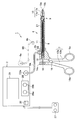
- FIG. 1 is a diagram showing an overall configuration of a high-frequency surgical apparatus according to a first embodiment of the present invention.
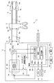
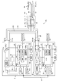
- FIG. 2 is a block diagram showing an internal configuration of a high frequency power supply device in the high frequency surgical apparatus.
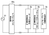
- FIG. 3 is a diagram showing an equivalent circuit of a high-frequency treatment instrument and living tissue.
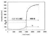
- FIG. 4 is a diagram illustrating a representative example of a change in impedance value measured by an impedance measurement unit in a state where a high-frequency current is supplied to a living tissue.
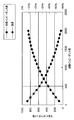
- FIG. 5 is a diagram showing the degree of error due to the combined impedance value and stray capacitance with respect to the tissue impedance value of the living tissue.
- FIG. 1 is a diagram showing an overall configuration of a high-frequency surgical apparatus according to a first embodiment of the present invention.
- FIG. 2 is a block diagram showing an internal configuration of a high frequency power supply device in the high frequency surgical apparatus.
- FIG. 3 is a diagram showing an equivalent circuit of
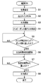
- FIG. 6 is a flowchart showing a processing procedure for performing a coagulation operation on a biological tissue to be treated according to the first embodiment.
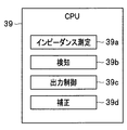
- FIG. 7A is a block diagram showing functional blocks of a CPU according to a modification of the first embodiment.
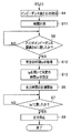
- FIG. 7B is a flowchart showing a part of the processing procedure in the modification.
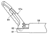
- FIG. 8 is a diagram showing an overall configuration of the surgical apparatus according to the second embodiment of the present invention.
- FIG. 9 is a block diagram showing an internal configuration of a high-frequency power supply device and an ultrasonic drive power supply device in the surgical apparatus.
- FIG. 10 is a diagram illustrating a representative example of a change in impedance value measured by the impedance measurement unit in a state where a high-frequency current and ultrasonic vibration are supplied to a living tissue.
- FIG. 11 is a diagram illustrating an example of setting a specific time.
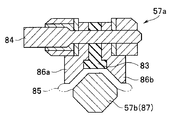
- FIG. 12A is a perspective view showing a treatment member on the distal end side of the probe in the second embodiment.
- 12B is a perspective view showing the inner structure of the treatment member of FIG. 12A.
- FIG. 12C is a transverse cross-sectional view when a living tissue is held by a pair of treatment members to perform coagulation and separation treatment.
- FIG. 12D is a cross-sectional view of the state where the treatment has progressed from the state of FIG.
- FIG. 13 is a flowchart showing a processing procedure for performing a coagulation and separation operation on a biological tissue to be treated according to the second embodiment.
- FIG. 14 is a flowchart showing a part of a processing procedure in a modification of the second embodiment.
- FIG. 15A is a flowchart showing processing obtained by modifying step S25 of FIG.
- FIG. 15B is an explanatory diagram of FIG. 15A.
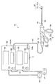
- the high-frequency surgical apparatus 1 As shown in FIG. 1, the high-frequency surgical apparatus 1 according to the first embodiment of the present invention has a high-frequency power supply device 2 as a high-frequency current supply unit for supplying a high-frequency current to a living tissue to be treated.
- the high-frequency power supply device 2 is provided with a connector receiver 3 that outputs a high-frequency current.
- a high-frequency probe (simply abbreviated as a probe) 4 constituting a high-frequency treatment instrument is connected to the connector receiver 3 with a cable portion 5A for connection.
- a connector 6a provided at the base end of the connector is detachably connected.
- the probe 4 can also be used using the cable part 5B shown with the dashed-two dotted line of the length different from the cable part 5A instead of the said cable part 5A.
- a probe having a different sheath length of the sheath 8 of the probe 4 is used, or a high-frequency treatment instrument in which the probe 4 and the cable portion 5A or 5B are integrated is connected to the high-frequency power supply device 2 for use. You can also
- the probe 4 is provided via an operation unit 7 that an operator holds and operates, a sheath 8 extended from the upper end side of the operation unit 7, and a link mechanism 9 at the distal end of the sheath 8. And a treatment unit 10 that performs sealing or coagulation treatment by supplying a high-frequency current to the target biological tissue.
- a slide pipe 11 is inserted into the sheath 8, and the rear end of the slide pipe 11 is connected to a connection bearing 14 at one upper end of one of the handles 13 a and 13 b forming the operation unit 7 via the connection shaft 12. .
- the connection bearing 14 is provided with a slit 14a that passes through the rear end side of the connection shaft 12 and does not pass through the ball portion at the rear end.
- the handles 13a and 13b are rotatably connected at the pivotal support portion 15, and finger-hanging portions 16a and 16b are provided on the lower end side.
- the operator moves the upper ends of the handles 13a and 13b in the opposite direction by performing an operation of opening and closing the finger hooks 16a and 16b. Then, the surgeon can push the slide pipe 11 forward or move backward by the above operation.
- the distal end of the slide pipe 11 is connected to a pair of treatment members 17a and 17b constituting the treatment section 10 via a link mechanism 9 for opening and closing.
- the operator can open and close the pair of treatment members 17a and 17b by driving the link mechanism 9 connected to the slide pipe 11 that moves forward and backward by performing an operation of opening and closing the handles 13a and 13b.
- the pair of treatment members 17a and 17b to be opened and closed forms a grasping portion for grasping, for example, a blood vessel 18 (see FIG. 2) or the like as a living tissue to be treated by two opposing inner surface portions inside.
- the treatment members 17a and 17b can be opened.
- Bipolar electrodes 19a and 19b are provided on opposing inner surface portions of the pair of treatment members 17a and 17b formed of insulating members. The rear ends of the treatment members 17a and 17b are connected to the link mechanism 9.
- a pair of cables 21 are inserted into the slide pipe 11 and connected to the electrodes 19a and 19b, respectively.
- the rear end of the cable 21 is connected to a connector receiver 22 provided at the upper end of the handle 13b, for example.
- the connector receiver 22 is detachably connected to the connector 6b at the other end of the cable portion 5A.
- the high frequency power supply 2 is connected with a foot switch 27 as an output switch for performing an instruction operation of output ON (energization) and output OFF (shut off) of the high frequency current.
- the surgeon can supply the high-frequency current to the treatment unit 10 side and stop the supply by performing an operation of stepping on the foot switch 27 with his / her foot.
- a setting unit 28 for setting the value of the high frequency power and the like is provided on the front surface of the high frequency power supply device 2.
- the setting unit 28 sets a high-frequency power value, a setting button 28a for setting an impedance threshold value Zth and a specific time (set time) ts described later, and a continuous output mode for continuously outputting a high-frequency current.
- An output mode selection switch 28b for selecting one of the intermittent output modes for intermittent output is provided. The surgeon is able to perform high-frequency surgery by setting a high-frequency power value suitable for treatment and setting an output mode to be used.
- a display unit 29 for displaying the set high-frequency power value and the like is provided.
- the high frequency power supply device 2 includes a high frequency current generating unit 31 that generates a high frequency current using an insulating transformer 32.
- a parallel resonant circuit having a capacitor connected in parallel is provided on the primary winding side of the insulating transformer 32.
- a DC voltage is applied from one end of the parallel resonant circuit from the variable power supply 34, and a switching circuit 35 is connected to the other end.
- the variable power supply 34 can output a variable DC voltage.
- the switching circuit 35 performs switching by applying a switching control signal from the switching control signal generator 36.
- the switching circuit 35 switches the current flowing from the variable power source 34 to the primary winding of the isolation transformer 32 and is insulated from the primary winding side at the output portion on the secondary winding side of the isolation transformer 32. , Generating a boosted high frequency current.
- a capacitor is also connected to the secondary winding.
- the output part on the secondary winding side of the insulating transformer 32 is connected to the contacts 3a and 3b of the connector receiver 3 serving as an output end of the high-frequency current. Then, a high-frequency current is transmitted to the probe 4 via the cable 23 in the cable portion 5 ⁇ / b> A connected to the connector receiver 3.
- the high-frequency current transmitted to the probe 4 is transmitted to the electrodes 19a and 19b via the cable 21 in the probe 4, and the high-frequency current is supplied to the blood vessel 18 or the like as a living tissue to be treated that is in contact with the electrodes 19a and 19b. Is supplied (applied) so that coagulation (sealing) can be performed.
- the high-frequency current transmission member (as a cable portion) that transmits a high-frequency current from the high-frequency current generation portion 31 to the electrodes 19a and 19b is the cable portion 5A and the in-probe cable 21 in FIG. In the case of a probe in which 5A is integrated with the probe 4, it becomes an in-probe cable.
- a voltage sensor 37a for measuring voltage and a current sensor 37b for measuring current are provided at both ends of the output unit.
- the voltage sensor 37a represents the voltage between the output terminals (two contacts 3a, 3b) and the current flowing to the load (biological tissue) side in a state where a high-frequency current is passed through, for example, a blood vessel 18 as a biological tissue. And the current sensor 37b.
- the voltage value and the current value respectively measured by the voltage sensor 37a and the current sensor 37b are input to the CPU 39 constituting the control unit 38.
- the CPU 39 divides the voltage value from the measured voltage value and current value by the current value to measure (calculate) an electrical impedance value (simply abbreviated as impedance value) Z (t) on the load side including the living tissue. It has the function of the impedance measuring unit 39a.
- Z (t) represents that the value changes according to the time t (elapsed time) after supplying (outputting) the high-frequency current to the living tissue and starting the treatment.
- the impedance measurement unit 39a may be provided outside the control unit 38 or the CPU 39, and the measured (calculated) impedance value Z (t) may be output to the control unit 38 or the CPU 39. Moreover, you may define the impedance measurement part 39a by the structure containing the voltage sensor 37a and the current sensor 37b.
- the CPU 39 monitors the measured impedance value Z (t) and detects (or determines) whether or not the impedance threshold Zth as a specific impedance value set according to the characteristics of the living tissue has been reached. (Or determination part) It has the function of 39b.
- the impedance threshold value Zth corresponds to a specific impedance value indicated by the living tissue in a state in which moisture in the living tissue starts to evaporate as described later.
- the CPU 39 constituting the control unit 38 includes a timer 41 as a time measurement unit 41a that performs time measurement, a memory 42 as a storage unit that stores various information such as an impedance threshold value Zth, a specific time ts, and the like. It is connected to a foot switch 27, a setting unit 28, and a display unit 29 as output switches for turning the output ON and OFF.
- CPU39 which comprises the control part 38 which controls each part of the high frequency power supply device 2 sends out the control signal for controlling the operation
- the variable power supply 34 outputs a DC voltage corresponding to the control signal sent from the CPU 39.
- the switching control signal generator 36 outputs a switching signal having a waveform (for example, a rectangular wave) corresponding to the control signal sent from the CPU 39.
- the high-frequency current generator 31 generates a high-frequency current by the operation of the switching circuit 35 that is turned on and off by the DC power sent from the variable power supply 34 and the rectangular wave sent from the switching control signal generator 36, and the connector receiver 3 Output from. Note that the parallel resonance circuit of the primary winding of the insulating transformer 32 reduces spurious due to the rectangular wave obtained by the switching operation.
- the output unit also forms a resonance circuit to reduce spurious.
- the CPU 39 controls each part when performing a coagulation treatment on the living tissue according to the program stored in the memory 42.
- the CPU 39 sets the specific time ts stored in the memory 42 in the timer 41 at the timing when it is detected that the measured impedance value Z (t) has reached the impedance threshold value Zth by the function of the detection unit 39b. Then, the timer 41 is caused to measure a specific time ts. The timer 41 starts measuring the output time when the high-frequency current is output to the living tissue side from the timing when the impedance value Z (t) reaches the impedance threshold Zth, and the output time is a specific time when the coagulation treatment is completed. A timing signal is output to the CPU 39 at the timing when the time ts is reached.
- the CPU 39 may simply cause the timer 41 to measure the output time and determine whether or not the output time measured by the timer 41 has reached a specific time ts.
- the CPU 39 sends a control signal for setting the power supply voltage of the variable power supply 34 to zero, for example, at the timing of detecting that the specific time ts has been reached, and sets the power supply voltage of the variable power supply 34 to zero, thereby causing the high-frequency current generating unit 31 to Control to stop output from.
- the CPU 39 supplies (outputs) the living tissue from the high-frequency power supply device 2 as the high-frequency current supply unit after the elapse of a specific time ts from the timing when the measured impedance value Z (t) reaches the impedance threshold value Zth.
- the function of the output control part 39c which performs control to stop supply (stop output) of the high frequency current to be performed.
- the output control part 39c performs control which stops supply (output) of a high frequency current
- it is not limited to the control which sets the power supply voltage of the said variable power supply 34 to zero with the said control signal
- the high frequency power supply device 2 Any control signal (referred to as an output stop signal) that stops the high-frequency current output from the body to the living tissue side may be used.
- FIG. 3 shows an equivalent circuit of the high-frequency treatment tool and the living tissue in the treatment state in which the high-frequency current is passed through the living tissue in the present embodiment.
- the frequency of the high-frequency current generated by the high-frequency current generator 31 in the present embodiment is about 350 kHz, and generally a frequency from 300 kHz to 500 kHz is used in the high-frequency surgical apparatus.
- the high-frequency treatment instrument and the biological tissue that are loads for the high-frequency current generated by the high-frequency current generating unit 31 include the impedance value Za of the stray capacitance Ca by the cable unit 5I and the stray capacitance by the cable 21 in the probe 4.
- the impedance value Zb of Cb and the impedance value (referred to as tissue impedance value) Zl (t) of the living tissue are represented by an equivalent circuit connected in parallel.
- impedance measurement Z (t) on the living tissue side during the treatment is provided in the high-frequency power supply device 2.
- the progress of the sealing or coagulation treatment is monitored by measurement by the unit 39a.
- the impedance value actually measured by the impedance measuring unit 39a is the combined impedance value Z (t) of the impedance value Zab of the stray capacitance Ca + Cb and the tissue impedance value Zl (t) connected in parallel.
- FIG. 4 shows a characteristic example of the temporal change of the impedance value Z (t) measured by the impedance measuring unit 39a when a treatment is performed by supplying a high-frequency current to the living tissue.
- the horizontal axis in FIG. 4 indicates the output time of the high frequency current when the time when the treatment is started by supplying the high frequency current is 0, and the vertical axis indicates the impedance value Z (t).
- cable portions 5I and probes 4 having different cable lengths and sheath lengths are used depending on the treatment.
- a sheath length of about 100 mm is generally used.
- a sheath length of about 300 mm is generally used.
- the tissue impedance value Zl (t) of the living tissue increases rapidly from the initial value of about 200-300 ⁇ when the water in the living tissue evaporates and begins to dehydrate. In the meantime, it increases from the initial value to about 1000-1500 ⁇ , which is several times higher. Therefore, even if the detection unit 39b determines that the impedance threshold has been reached when the impedance value is several times the initial impedance value of the living tissue measured by the impedance measurement unit 39a at the start of the supply of the high-frequency current. Good.
- FIG. 4 shows a typical example of the impedance value Z (t) measured by the impedance measuring unit 39a when the stray capacitance Ca + Cb is included, and the time when the moisture in the living tissue evaporates and begins to dehydrate ( In the vicinity of approximately 15000 ms, the tissue impedance value Zl (t) of the living tissue changes from an initial value to a value several times or more in a short time.
- the output of the high-frequency current is stopped at the timing when the impedance value Z (t) measured by the impedance measuring unit 39a reaches a predetermined impedance value in a state where the coagulation with respect to the living tissue is completed.
- the impedance measuring unit 39a measures the combined impedance value Z (t) with the tissue impedance value Zl (t) connected in parallel to the stray capacitance Ca + Cb, the impedance due to the stray capacitance Ca + Cb with respect to the tissue impedance value Zl (t). The value becomes an error and greatly affects the measurement accuracy, particularly in the high impedance region.
- FIG. 5 shows the combined impedance value and the degree of error when the value of the stray capacitance Ca + Cb is, for example, about 300 pF and the impedance value Zab is regarded as an error with respect to the tissue impedance value Zl.
- the synthetic impedance value can be measured (detected) with a relatively small error in the region where the tissue impedance value Zl is small, but is measured with a small error in the high impedance region where the tissue impedance value Zl is large. It becomes difficult.
- the tissue impedance value Zl falls within the range of 500 ⁇ or less (100 ⁇ -500 ⁇ ) as shown by the dotted line.
- the synthetic impedance value is measured as in the conventional example, and it is determined whether or not the measured synthetic impedance value has reached a predetermined impedance value in a state where coagulation is completed, the predetermined impedance value is determined.
- the impedance measuring unit 39a does not directly measure the predetermined impedance value in the state where the coagulation is expected to be reduced in accuracy, but is in a state before the coagulation is completed, and more accurate. It is measured whether or not the impedance threshold Zth at which water in the living tissue that can be well measured starts to evaporate is reached.
- the impedance threshold value Zth is set within a range of 100 ⁇ -500 ⁇ so that it can be accurately measured whether or not the impedance threshold value Zth has been reached.
- the output control unit 39c performs control to stop the output of the high-frequency current.
- the specific time ts in this embodiment is set to a value obtained by adding the margin time to the time required from the time when the water in the living tissue starts to evaporate until the coagulation is completed.
- the specific time ts is set according to the size of the biological tissue to be treated, the amount of water contained in the biological tissue, and the gripping area for gripping the biological tissue in the probe 4 to be used. Thus, the specific time ts is set within a range of 100 ms to 20000 ms.
- the upper limit value is set so that sufficient coagulation treatment can be performed. 20000 ms is set.
- the surgeon can set the impedance threshold Zth and the specific time ts by the setting unit 28.
- the impedance threshold Zth can be set to a range wider than 100 ⁇ -500 ⁇ , for example, about 100 ⁇ -1500 ⁇ when an error of about 50% is allowed, for example, when a larger error is allowed.
- the surgeon turns on the power switch 26 and performs initial settings such as the value of the high frequency power, the impedance threshold value Zth, the specific time ts, and the output mode when performing treatment as shown in step S1.
- the surgeon selects a continuous output mode for continuously outputting a high-frequency current as the output mode.
- the surgeon grasps the blood vessel 18 as a biological tissue to be treated with the electrodes 19a and 198b of the treatment portion 10 at the distal end portion of the probe 4 shown in FIG.
- a state in which the blood vessel 18 is held by the electrodes 19a and 19b is schematically shown in FIG.
- the operator turns on the foot switch 27 as an output switch in order to perform coagulation treatment on the blood vessel 18 as shown in step S2.
- An output switch may be provided on the probe 4.
- the CPU 39 controls the high frequency current generating unit 31 to generate a high frequency current.
- the high-frequency current generating unit 31 outputs a high-frequency current from the output end, and the cable unit 5A and the cable 21 in the probe 4 transmit the high-frequency current to the blood vessel 18 that is in contact with the electrodes 19a and 19b. ) Supply.
- a high-frequency current flows through the blood vessel 18 to start the coagulation treatment. That is, the output of high-frequency current starts in step S3 of FIG.
- step S4 the impedance measuring unit 39a of the CPU 39 takes in the impedance value Z (t) at a predetermined period. That is, the impedance measuring unit 39a starts measuring the impedance value Z (t).
- the detection unit 39b of the CPU 39 determines whether or not the captured impedance value Z (t) has reached a preset impedance threshold Zth, that is, whether Z (t) ⁇ Zth. Detect (judgment).
- step S ⁇ b> 6 the CPU 39 causes the timer 41 to start measuring the output time for measuring the coagulation completion time.
- the timer 41 starts measuring the output time during which the high-frequency current is output to the living tissue side from the timing when the impedance value Z (t) reaches the impedance threshold value Zth.
- the timer 41 or the CPU 39 determines whether or not the output time has reached a specific time ts.
- step S8 the output control unit 39c of the CPU 39 performs control to stop the output of the high-frequency current. Then, the CPU 39 performs control to display on the display unit 29 that the coagulation treatment is completed, and ends the coagulation treatment shown in FIG.
- the coagulation (sealing) procedure for the blood vessel 18 as a living tissue has been described with the high-frequency surgical apparatus 1, the coagulation procedure can be similarly performed on other living tissue such as a ligament tissue.
- the influence of stray capacitance due to the length of the cable portion 5I and the cable 21 in the probe 4 can be reduced, and the coagulation treatment can be appropriately performed on the living tissue.
- the temporal change in the impedance value Z (t) is small, and therefore, from the impedance threshold corresponding to the completion of the coagulation treatment (relative If it is set to a slightly large value (within a range that is not large as an error), high-frequency current may continue to be output in vain (that is, empty output) even after coagulation treatment is actually completed. appear. In this case, the operation time is prolonged.
- the impedance threshold corresponding to the completion of the coagulation treatment is set to a slightly small value (within a relative error that is not large), the coagulation is completed before the coagulation is actually completed. In some cases, the output of the high-frequency current is stopped after the determination.
- the impedance threshold value it is necessary to consider stray capacitance, and it is difficult to appropriately determine that coagulation is completed only from impedance measurement. It is also susceptible to noise.
- the method of measuring the time from the start of the supply (output) of the high-frequency current and stopping the output of the high-frequency current when the output time threshold set corresponding to the completion of the coagulation treatment is reached is as follows. Depending on the value or the like, it is difficult to set the output time threshold appropriately.
- the following configuration may be used. From the time when the high-frequency current is started to be supplied to the living tissue side (output start) by the time measuring unit 41a until the detection unit 39b detects that the impedance threshold Zth when the moisture in the living tissue starts to evaporate is reached. A predetermined time (detection time) tr is measured, and a specific time ts is corrected or set according to the predetermined time tr.
- the thickness of the living tissue to be treated When moisture in the living tissue starts to evaporate according to the value of the high-frequency current used for the actual treatment set by the operator, the thickness of the living tissue to be treated, and the size (width) (impedance threshold Zth) ) To the completion of the coagulation treatment is expected to be influenced by the value of the high-frequency current and the like.
- a predetermined time tr is measured as the time from the start of output until the impedance value Z (t) measured by the impedance measuring unit 39a reaches the impedance threshold value Zth.
- a correction coefficient tr / trs for correcting the specific time ts before correction is set based on the predetermined time (standard time) trs set as a standard value according to the measured predetermined time tr.
- the specific time ts before correction is corrected by this calculation and the correction coefficient tr / trs. In this case, the specific time ts before correction is corrected in proportion to the value of the actually measured predetermined time tr.
- the CPU 39 shown in FIG. 7A in the modification for performing such correction further includes a correction unit 39d in the configuration shown in FIG. 2, and the correction unit 39d corrects the correction coefficient tr / trs at a specific time ts before correction.
- the output control unit 39c performs control to stop the output of the high-frequency current.
- the procedure of the treatment according to the modified example includes the process of step S11 between step S4 and step S5 in the procedure of FIG. Further, Steps S12 and S13 are inserted between Step S5 and Step S6, and replaced with Step S7 ′ replaced with the specific time ts ′ instead of the specific time ts in Step S7.
- step S1 to step S4 is performed as in the case of FIG.
- step S2 When the output switch in step S2 is turned on, output starts in step S3, and in step S4, the impedance value Z (t) starts to be taken. And with the process of step S4, the time measurement part 41a of the timer 41 starts time measurement in step S11. Note that the timer 41 measures the output time in the same manner as the output time measurement in step S6 described later. Therefore, the measurement of the output time in step S6, which will be described later, can be regarded as the measurement of the first output time, and step S11 can be regarded as the measurement of the second output time.
- the detection unit 39b detects whether or not the measured impedance value Z (t) has reached a specific impedance value, that is, the impedance threshold value Zth.
- the time measuring unit 41a by the timer 41 further acquires the value of the predetermined time tp in that case in step S12.
- the correction unit of the CPU 39 corrects the specific time ts (before correction) by the correction coefficient tp / tps and sets the specific time ts ′.
- the time measuring unit 41a starts measuring the output time when the impedance value Z (t) reaches the impedance threshold value Zth.
- step S7 ′ the output control unit 39c measures whether or not the measured output time has reached a specific time ts ′.
- the output is stopped as shown in step S8.
- FIG. 8 shows a surgical apparatus 1C according to the second embodiment of the present invention.
- the high-frequency surgical apparatus 1 performs a coagulation treatment using a high-frequency current.
- the surgical apparatus 1C of the present embodiment uses a high-frequency current and ultrasonic vibration at the same time to treat a blood vessel or the like. Coagulation and detachment are performed on the target biological tissue. By using both high-frequency current and ultrasonic vibration, treatment from coagulation to separation can be performed in a short time.
- the surgical apparatus 1C includes an ultrasonic transducer 51 that further performs ultrasonic vibration instead of the probe 4 having a treatment function using a high-frequency current in the first embodiment (including the high-frequency power supply device 2). It has a probe 4C as a high-frequency & ultrasonic treatment tool that is built-in and has a treatment function by high-frequency current and a treatment function by ultrasonic vibration.
- the surgical apparatus 1C includes an ultrasonic drive power supply device 52 that supplies an ultrasonic drive signal for ultrasonically vibrating the ultrasonic transducer 51.
- the ultrasonic drive power supply device 52 includes an ultrasonic drive.
- a foot switch 53 is connected as an output switch for turning on / off the signal output.
- the connectors 6a and 6d at the other end of the cable portion 5C in which the connector 6c is connected to the connector 54 of the probe 4C are the connector receiver 3 of the high-frequency power supply device 2 and the ultrasonic drive power supply device 52, respectively. Each is connected to a connector receiver 55.
- one cable portion 5C is branched into two in the middle and connectors 6a and 6d are provided at each end, but may be formed by two cables.
- surgery can be performed using a cable portion (not shown) different from the cable length of the cable portion 5C.
- a probe having a different sheath length from that of the probe 4C shown in FIG. 8 can be used.
- the ultrasonic drive power supply device 52 transmits the ultrasonic drive signal to the cable portion. This is supplied to the ultrasonic transducer 51 via the 5C cable 23 '(see FIG. 9), and the ultrasonic transducer 51 is ultrasonically vibrated.
- the operation portion 7 is provided with handles 13a and 13b having finger hook portions 16a and 16b, respectively.
- the treatment members 57a and 57b forming the treatment portion 56 provided at the distal end of the sheath 58 by opening and closing the handle 13b with respect to the handle 13a is treated member 57b. Open and close against.
- the ultrasonic transducer 51 is ultrasonically vibrated by the ultrasonic drive signal. As shown in FIG. 9, the ultrasonic vibration generated by the ultrasonic vibrator 51 is arranged in the sheath 58, and the proximal end of the ultrasonic vibration is applied to the treatment member 57 b by the ultrasonic transmission member 61 connected to the ultrasonic vibrator 51. Communicated.
- the ultrasonic vibration generated by the treatment member 57b is supplied to the living tissue grasped by the treatment members 57a and 57b. Therefore, the ultrasonic transducer 51, the ultrasonic transmission member 61, and the treatment member 57b form an ultrasonic supply unit that supplies ultrasonic vibration to the living tissue. In a narrow sense, the treatment member 57b forms an ultrasonic supply unit that supplies ultrasonic vibrations to the living tissue.
- the high frequency current from the high frequency power supply device 2 is transmitted to the tip electrode through the cable 23 in the cable portion 5C and the cables 21a and 21b in the probe C.
- the treatment member 57a is provided with electrodes 86a and 86b on both sides of the central pad member 83 as shown in FIG. 12C and the like, and the treatment member 57b is provided with electrodes 87 facing the electrodes 86a and 86b.
- the ultrasonic transmission member 61 serves as a part of the cable 21b, the cable 21b may be configured not to be used as the ultrasonic transmission member 61.
- the ultrasonic drive power supply device 52 is also provided with a setting unit 68 for setting the value of the ultrasonic output and a display unit 69 for performing various displays.
- the high frequency power supply device 2 and the ultrasonic drive power supply device 52 are connected by a communication cable 67 that performs communication.
- an oscillation circuit 71 is provided in the ultrasonic driving power supply device 52, and the oscillation signal of the oscillation circuit 71 is shaped into a signal having a waveform suitable for performing treatment such as coagulation or separation. Is input to the waveform shaping circuit 72. The output signal of the waveform shaping circuit 72 is amplified by the amplifier 73 and then input to the transformer 74. The transformer 74 insulates the input signal from the output signal and boosts it to output it as an ultrasonic drive signal.
- This ultrasonic drive signal is output to the high frequency & ultrasonic treatment instrument connected to the connector receiver 55 via the switch circuit 75 for turning this signal ON / OFF.
- an ultrasonic drive signal is supplied (applied) to the ultrasonic transducer 51 of the probe 4C, and the ultrasonic transducer 51 is subjected to ultrasonic vibration. To do.
- a CPU 77 constituting a control unit 76 for controlling operations of the waveform shaping circuit 72, the amplifier 73, the switch circuit 75, and the like is provided.
- the CPU 77 is connected to a foot switch 53, a timer 78 for measuring time, and a memory 79 for storing various information.
- the CPU 77 has a function of an output control unit 77a for turning on / off the switch circuit 75 in response to an output instruction and an output stop instruction operation of the foot switch 53. Further, the CPU 77 performs control corresponding to the output setting by the setting unit 68.
- the CPU 39 constituting the control unit 38 of the high frequency power supply device 2 as one of the two devices sends a control signal or the like to the ultrasonic drive power supply device 52 via the communication cable 67 constituting the communication unit.
- the operation of the ultrasonic drive power supply device 52 is controlled in conjunction with the operation of the high frequency power supply device 2.
- the function of the linked operation is set to ON by the communication control units 39e and 77b
- the foot switch 27 is turned ON or OFF, the output start or output stop of the high frequency power supply device 2 and the ultrasonic drive power supply device 52 is started. It can be carried out.
- the operation of both devices can be controlled by an instruction operation using only one foot switch 27.
- the memory 42 stores information on the specific time ts2 required until the living tissue is separated from the timing when the impedance threshold Zth is reached when the moisture in the living tissue starts to evaporate.
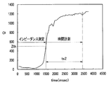
- FIG. 10 shows a representative example of a change in the impedance value Z (t) measured by the impedance measuring unit 39a in a state where the living tissue in the present embodiment is coagulated and separated.
- the impedance measurement unit 39a measures the impedance value Z (t) on the biological tissue side, and the detection unit 39b detects the moisture in the biological tissue. It is detected that the impedance threshold Zth at which evaporation starts is reached.
- impedance measurement is performed from the time when treatment is started (that is, high frequency and ultrasonic output start), and the detection unit 39b detects that the impedance value Z (t) has reached the impedance threshold value Zth (FIG. 10).
- the impedance threshold value Zth is reached, it is around 1500 ms from the start of treatment).
- the time measuring unit 41a by the timer 41 measures a specific time ts2 until the living tissue is separated from the timing when it is detected that the impedance threshold Zth when the moisture in the living tissue starts to evaporate is reached.
- the output control unit 39c of the CPU 39 stops the output of the high frequency current.
- the specific time ts2 is around 3400 ms.
- the specific time ts2 is set so as to include the time required for completion of coagulation from the time when the water in the living tissue starts to evaporate and further to complete the separation.
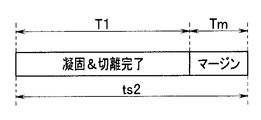
- FIG. 11 shows a setting example of the specific time ts2.
- a specific time ts2 is a time T1 required for completion of coagulation from the time when moisture in the living tissue starts to evaporate and further completion of separation.
- a margin time Tm (to continue the treatment to ensure separation completion) is set to a value added.
- the specific time ts is set to a value obtained by adding the margin time to the time required from when the moisture in the living tissue starts to evaporate to completion of coagulation.
- the time T1 required for completion of the separation after completion of coagulation has a statistically different value in the case where the biological tissue is, for example, a ligament tissue, blood vessel, or thin film tissue.
- the specific time ts2 may be set by the setting unit 28 according to the above.
- the impedance threshold value Zth is set to a range of 500 ⁇ or less (100 ⁇ 500 ⁇ ) as in the first embodiment, but since ultrasonic waves are also used, the specific time ts2 is set to the first time ts2. It is set to a narrower range (100 ms-10000 ms) than in the first embodiment.
- the communication control unit 39e of the CPU 39 sends a control signal for stopping the output to the CPU 77 via the communication cable 67.
- the CPU 77 stops outputting the ultrasonic drive signal, and the ultrasonic vibrator 51 stops the ultrasonic vibration. Therefore, the CPU 39 (CPU 77 in the narrow sense) in a broad sense performs control to stop the ultrasonic vibration in the living tissue.
- 12A and 12B show the configuration of the treatment member 57a on the distal end side of the probe 4C.
- 12C and 12D show a cross section at the position of the fixing screw 84.
- FIG. the distal end portion of the sheath 58 is provided with a protruding piece 81 that protrudes in a pair on the left and right sides, and the proximal end portion of the treatment member 57 a is rotatable on the protruding piece 81 via a fulcrum pin 82. Is attached. 12A and 12B, the treatment member 57b protruding from the inside of the sheath 58 to the distal end side is not shown.
- the living tissue between the treatment member 57b that is ultrasonically vibrated is provided in the groove provided in the longitudinal direction inside the treatment member 57a, that is, the inside facing the treatment member 57b (the upper surface).
- the pad member 83 is fixed to the treatment member 57b by a fixing screw 84.
- the treatment member 57b may be formed of a plurality of members.
- the treatment member 57 b and the pad member 83 that vibrate ultrasonically with respect to the biological tissue 85 indicated by a two-dot chain line held between the treatment members 57 a and 57 b facing vertically.
- the treatment by ultrasonic vibration is performed.
- a cauterization treatment using a high-frequency current supplied to a living tissue can be performed.
- FIG. 12C shows a state immediately before the separation of the living tissue 85 is completed, and when the separation is completed, the gripping surfaces of the pad member 83 and the upper surface of the treatment member 57b come into contact as shown in FIG. 12D. It becomes a state. In this case, a small gap (clearance) is formed between the electrode 86a on both sides of the gripping surface and the electrode 87 by the treatment member 57b, and between the electrode 86b and the electrode 87.
- the pad member 83 and the treatment member 57b forming the gripping surface facing the pad member 83 are worn or damaged. End up.
- the living tissue 85 sticks to the electrodes 86a, 86b, 87, etc., so that the operator cannot visually recognize the completion of the separation where the living tissue 85 is cut off.
- the ultrasonic output may be continued, which causes wear and damage to the member that forms the gripping surface that performs solidification and separation.
- the surgeon turns on the power switch 26 and the high frequency power value, the ultrasonic drive signal power value, the high frequency current output mode, the ultrasonic drive signal waveform, and the impedance threshold Zth when the treatment is performed as shown in step S21.
- Initial setting such as a specific time ts2 is performed.
- the surgeon grasps the living tissue to be treated by the treatment portion 56 at the distal end portion of the probe 4C.
- the surgeon turns on the foot switch 27 as an output switch in order to perform treatment as shown in step S22.
- the CPU 39 by the output control unit 39c of the control unit 38 controls the high frequency current generating unit 31 to generate a high frequency current.
- the high-frequency current generating unit 31 outputs a high-frequency current from the output end, and the cable 23 in the cable unit 5C and the cable 21 in the probe 4C transmit the high-frequency current and contact the treatment members 57a and 57b that also serve as electrodes.
- a high frequency current is supplied to living tissue.
- the CPU 39 sends a control signal for turning on the output to the CPU 77 of the ultrasonic drive power supply device 52 via the communication cable 67, and the CPU 77 turns on the switch circuit 75 and outputs the ultrasonic drive signal from the transformer 74. Control.
- the ultrasonic drive signal is supplied to the ultrasonic vibrator 51, and the ultrasonic vibrator 51 vibrates ultrasonically, and supplies the ultrasonic vibration to the living tissue via the ultrasonic transmission member 61 by the treatment member 57 b at the tip thereof.
- step S23 the output of the high-frequency current and the ultrasonic vibration to the living tissue is started, and the treatment for the living tissue is started.
- the impedance measuring unit 39a of the CPU 39 takes in the impedance value Z (t) at a predetermined period. That is, the impedance measuring unit 39a starts measuring the impedance value Z (t).
- the detection unit 39b of the CPU 39 determines whether or not the captured impedance value Z (t) has reached a preset impedance threshold value Zth, that is, whether Z (t) ⁇ Zth. Detect (determine).
- step S ⁇ b> 26 the CPU 39 causes the timer 41 to start measuring the output time.
- the timer 41 starts measuring the output time during which high-frequency current and ultrasonic vibration are output to the living tissue side from the timing when the impedance value Z (t) reaches the impedance threshold value Zth.
- the time measuring unit 41a or the CPU 39 of the timer 41 determines whether or not the output time has reached a specific time ts2.
- the output control unit 39c of the CPU 39 performs control to stop the output of the high-frequency current in step S28. Also, a control signal for stopping the output of the ultrasonic drive signal is sent to the CPU 77 via the communication cable 67, and the CPU 77 turns off the switch circuit 75 to stop the output of the ultrasonic drive signal. Then, the ultrasonic vibrator 51 stops ultrasonic vibration.
- the CPU 39 performs control to display on the display unit 29 that the coagulation and separation treatment is completed, and the treatment shown in FIG.
- the present embodiment has an effect similar to that of the first embodiment, in which the influence of stray capacitance due to the length of the cable 21 in the cable portion 5C and the probe 4C is reduced, so that coagulation and cutting of the living tissue can be achieved. Separation treatment can be appropriately performed.
- a specific time ts2 obtained by acquiring a predetermined time tp by time measurement and correcting the specific time ts2 by the acquired predetermined time tp. ′ May be set.
- step S31 for measuring time is inserted between steps S24 and S25 in FIG. Further, after steps S25 and S26 in FIG. 13, a step S32 for obtaining a predetermined time tp and a step S33 for setting a specific time ts2 ′ using the predetermined time tp are inserted.
- the specific time ts2 in step S27 in FIG. 13 is replaced with ts2 ′ to become step S27 ′.
- the coagulation treatment using only the high-frequency current in the modification of the first embodiment is replaced with the coagulation and separation treatment using the high-frequency current and the ultrasonic vibration, and the completion of the coagulation is changed to the completion of the separation. It becomes the effect which read.
- steps S21 to S24 are the same as those in FIG.
- the impedance measuring unit 39a of the CPU 39 takes in the impedance value Z (t) at a predetermined cycle.
- the time measuring unit 41a by the timer 41 starts measuring time in step S31.
- step S25 the detection unit 39b detects that the measured impedance value Z (t) has reached the impedance threshold value Zth.
- the timer 41 acquires the measured time as a predetermined time tp as shown in step S32.
- the correction unit formed by the CPU 39 in step S33 corrects the specific time ts2 using the acquired predetermined time tp, and sets the specific time ts2 ′.
- step S26 the timer 41 measures the output time. This step S26 is a process of measuring the output time from the detection by the detection unit 39b until the separation is completed.
- step S26 The processes after step S26 are the same as those in FIG. However, ts2 'is used for the specific time in step S27'.
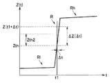
- the tissue impedance value Zl (t) of the living tissue rapidly increases in a short time in the vicinity of the moisture in the living tissue starts to evaporate.
- region which shows this characteristic is shown in FIG.
- the detection unit 39b detects that the impedance value Z (t) measured by the impedance measurement unit 39a has reached the impedance threshold value Zth in step 25 of FIG. Processing as shown in 15A may be performed.
- the detector 39b when it is detected in step S25 that the impedance value Z (t) has reached the impedance threshold value Zth, the detector 39b further detects the measured impedance value Z (t in the short time ⁇ t in step S25 ′. ) Is detected as to whether or not the impedance change amount ⁇ Z ( ⁇ t) has changed to the second impedance threshold value Zth2 or more.
- a low impedance region Rl corresponding to a region where impedance measurement is performed and a high impedance region Rh corresponding to a region where time measurement is performed are also schematically illustrated.
- the detection unit 39b has an impedance change amount ⁇ Z ( ⁇ t) during the subsequent short time ⁇ t, It is detected whether or not it has changed (specifically increased) to the second impedance threshold value Zth2 or more.
- the impedance change amount ⁇ Z ( ⁇ t) is shown as exceeding the second impedance threshold value Zth2.
- step S25 If the impedance change amount ⁇ Z ( ⁇ t) has not changed to the second impedance threshold value Zth2 or more, the process returns to step S25.
- the impedance change amount ⁇ Z ( ⁇ t) changes to the second impedance threshold Zth2 or more
- the impedance value Z (t) measured by the impedance measuring unit 39a starts to evaporate moisture in the living tissue. It is detected (determined) that the impedance state corresponding to is reached, and the process proceeds to the next step S32.
- the detection unit 39b by the CPU 39 has a function of a temporal impedance change amount detection unit or a determination unit that detects or determines a temporal impedance change amount with respect to the impedance value Z (t) measured by the impedance measurement unit 39a. .
- the value of the second impedance threshold value Zth2 can be set corresponding to the characteristic that the impedance value Zl (t) of the living tissue rapidly increases in a short time.
- the second impedance threshold Zth2 may be set to 100 ⁇ or more.
- the value of the short time ⁇ t can be appropriately set according to the second impedance threshold value Zth2.
- FIG. 15A illustrates the case of applying to FIG. 14, but the same applies to the cases of FIG. 6, FIG. 7B, and FIG. 13.
- the probes 4 and 4C are provided with a memory or the like that stores information such as the sheath length and the size of the gripping surface, and the connected high-frequency power supply device 2 reads the information stored in the memory and stores the information in the information. Accordingly, standard values such as specific times ts and ts2 may be automatically set.
- the detection unit 39b of the CPU 39 uses the impedance threshold value Zth when the impedance value Z (t) measured by the impedance measurement unit 39a starts to evaporate water in the living tissue. Detecting that
- the impedance threshold Zth in this case has been described as being set with respect to the impedance value Z (t) measured by the impedance measuring unit 39a (that is, including the stray capacitance and the biological tissue).
- the tissue impedance Zl (t) may be set so as to be set.
- the impedance value measured by the impedance measuring unit 39a without holding the living tissue is set as the impedance value Zab due to the stray capacitance.
- the impedance measuring unit 39a grips the living tissue and removes the impedance value Zab component from the impedance value Z (t) (that is, the combined impedance value) measured by the impedance measuring unit 39a.
- Zl (t) is calculated.
- the impedance threshold Zth when the water in the living tissue starts to evaporate may be set for the tissue impedance Zl (t). In this way, impedance measurement more closely corresponding to the living tissue can be performed.
Abstract
高周波手術装置は、処置対象の生体組織を把持するための把持部と、生体組織へ高周波電流を供給するための電極と、処置に必要な高周波電流を発生する高周波電流供給部、高周波電流を伝達するケーブル部と、生体組織のインピーダンス値を測定するインピーダンス測定部と、測定したインピーダンス値が生体組織中の水分が蒸発し始めるときのインピーダンス閾値に達したことを検知する検知部と、検知後から高周波電流の出力時間を計測する計測部と、高周波電流の出力時間が予め記憶された設定時間に達した時、出力停止する制御を行う出力制御部と、を有する。
Description
本発明は、高周波電流等を生体組織に供給して手術を行う高周波手術装置及び手術装置に関する。
近年、外科手術等において、各種の手術装置が使用されるようになっている。例えば、血管に対して高周波エネルギを投与して処置を行う技術が従来から知られている。この場合には、血管を適切な把持力量にて把持した状態で高周波電流を流し、その際に生ずる熱エネルギにより血管を封止する高周波手術装置が用いられる。
例えば、日本国特開平10-286261号公報の電気外科手術装置においては、生体組織に高周波電流を供給しながら生体組織の電気的インピーダンスを測定し、その電気的インピーダンスが閾値に達するか、又は一定時間後に、出力停止して処置を終了する。
しかし、血管の封止が完了した状態の電気的インピーダンスが閾値に達したか否かにより判定したり、一定時間で判定する方法では、個体差等があることを考慮すると、かなりのマージンを持たせて処置を行うことが必要となる。
このため、従来例の方法では血管の封止の処置が完了(又は終了)した状態を検出又は判定する精度が低くなり、その精度の低下分に対応して、実際に血管の封止の処置が完了した後にも高周波電流を流すことが行われる欠点がある。
本発明は上述した点に鑑みてなされたものであり、処置の完了に至る途中の特徴的なインピーダンス変化特性の検知を利用することにより、より精度良く処置の完了を検知して無駄に高周波電流を流すことを低減できる高周波手術装置及び手術装置を提供することを目的とする。
本発明の一態様に係る高周波手術装置は、処置対象の生体組織を把持するための把持部と、前記把持部に設けられ、前記生体組織へ高周波電流を供給するための電極と、前記電極を介して前記生体組織の処置に必要な前記高周波電流を発生させる高周波電流供給部と、前記高周波電流供給部で発生させた前記高周波電流を前記電極に伝達する高周波電流伝達部材と、前記生体組織のインピーダンス値を測定するためのインピーダンス測定部と、前記インピーダンス測定部により測定した前記インピーダンス値が前記生体組織中の水分が蒸発し始めるときのインピーダンス閾値に達したか否かを検知する検知部と、少なくとも前記検知部により前記生体組織のインピーダンス値が前記インピーダンス閾値に達したことを検知した後から前記高周波電流の出力時間を計測する時間計測部と、前記時間計測部によって計測された前記高周波電流の出力時間が予め記憶された設定時間に達したか否かを判断し、前記設定時間に達したと判断されたら前記高周波電流供給部へ前記高周波電流の出力停止信号を送信する出力制御部と、を有する。
本発明の一態様に係る手術装置は、処置対象の生体組織を把持するための把持部と、前記把持部に設けられ、前記生体組織に対して超音波振動により処置を行うための処置部材と、前記処置部材を介して前記生体組織へ前記超音波振動を供給するための超音波振動供給部と、前記処置部材に設けられ、前記生体組織に対して高周波電流により処置を行うための電極と、前記電極を介して前記生体組織へ前記高周波電流を供給するための高周波電流供給部と、前記高周波電流供給部から前記電極に供給される前記高周波電流を伝達する高周波電流伝達部材と、前記生体組織のインピーダンス値を測定するためのインピーダンス測定部と、前記インピーダンス測定部により測定した前記インピーダンス値が前記生体組織中の水分が蒸発し始めるときのインピーダンス閾値に達したことを検知する検知部と、少なくとも前記検知部により前記生体組織の前記インピーダンス値が前記インピーダンス閾値に達したことを検知した後から前記高周波電流及び前記超音波振動の出力時間を計測する時間計測部と、前記時間計測部によって計測された前記高周波電流及び前記超音波振動の出力時間が予め記憶された設定時間に達したか否かを判断し、前記設定時間に達したと判断されたら前記超音波振動供給部による超音波振動と前記高周波電流供給部による高周波電流との出力停止させる制御を行う出力制御部と、を有する。
以下、図面を参照して、本発明の各実施形態を説明する。
(第1の実施形態)
図1に示すように本発明の第1の実施形態に係る高周波手術装置1は、処置対象の生体組織に高周波電流を供給するための高周波電流供給部としての高周波電源装置2を有する。
図1に示すように本発明の第1の実施形態に係る高周波手術装置1は、処置対象の生体組織に高周波電流を供給するための高周波電流供給部としての高周波電源装置2を有する。
この高周波電源装置2は、高周波電流を出力するコネクタ受け3が設けられており、このコネクタ受け3には高周波処置具を構成する高周波プローブ(単にプローブと略記)4が、接続用のケーブル部5Aの基端に設けられたコネクタ6aが着脱自在に接続される。また、プローブ4は、上記ケーブル部5Aの代わりにケーブル部5Aとは異なる長さの2点鎖線で示すケーブル部5Bを用いて使用することもできる。
また、プローブ4の代わりに、このプローブ4のシース8のシース長が異なるプローブを用いたり、プローブ4とケーブル部5A又は5Bが一体化された高周波処置具を高周波電源装置2に接続して使用することもできる。
プローブ4は、術者が把持して操作を行う操作部7と、この操作部7の上端側から延出されたシース8と、このシース8の先端のリンク機構9を介して設けられ、処置対象の生体組織に対して高周波電流を流して封止又は凝固の処置を行う処置部10とを有する。
シース8内にはスライドパイプ11が挿通され、このスライドパイプ11の後端は、接続軸12を介して操作部7を形成するハンドル13a、13bの一方の上端の接続軸受け14に連結されている。なお、接続軸受け14には接続軸12の後端側を通し、その後端の球部分を通さないスリット14aが設けてある。
ハンドル13a、13bは、枢支部15において、回動自在に連結され、下端側に指掛け部16a、16bが設けてある。
術者は、指掛け部16a、16bを開いたり、閉じたりする操作を行うことにより、ハンドル13a、13bの上端側は反対方向に移動する。そして、術者は、上記操作により、スライドパイプ11を前方に押し出したり、後方に移動させたりすることができる。
このスライドパイプ11の先端には、開閉させるためのリンク機構9を介して処置部10を構成する対の処置部材17a、17bと連結されている。
従って、術者は、ハンドル13a、13bを開閉する操作を行うことにより、進退移動するスライドパイプ11に連結されたリンク機構9を駆動して、対の処置部材17a、17bを開閉させることができる。そして、開閉する対の処置部材17a、17bは、その内側における対向する2つの内面部分により、処置対象の生体組織として例えば血管18(図2参照)等を把持する把持部を形成する。
なお、図1の状態は、ハンドル13a、13bを閉じた状態であり、この状態からハンドル13a、13bを開く操作を行うと、スライドパイプ11が前方に移動し、リンク機構9を介して対の処置部材17a、17bを開くことができる。
絶縁部材で形成された対の処置部材17a、17bにおける、対向する内面部分にバイポーラの電極19a,19bが設けられている。処置部材17a、17bの後端側はリンク機構9と連結している。
スライドパイプ11内には対のケーブル21が挿通され、電極19a、19bとそれぞれ接続されている。また、ケーブル21の後端は、例えばハンドル13bの上端に設けたコネクタ受け22に接続される。このコネクタ受け22にはケーブル部5Aの他端のコネクタ6bが着脱自在に接続される。
高周波電源装置2には、電源スイッチ26の他に高周波電流の出力ON(通電),出力OFF(遮断)の指示操作を行う出力スイッチとしてのフットスイッチ27が接続されている。術者は、このフットスイッチ27を足で踏む操作を行うことにより、処置部10側に高周波電流の供給と、供給の停止をすることができる。
また、高周波電源装置2の前面には、高周波電力の値等の設定を行う設定部28が設けられている。この設定部28には高周波電力の値を設定したり、後述するインピーダンス閾値Zth,特定の時間(設定時間)tsの値を設定する設定ボタン28aと、高周波電流を連続して出力する連続出力モード及び間欠して出力する間欠出力モードの一方の出力モードの選択を行う出力モード選択スイッチ28bが設けてある。術者は処置に適した高周波電力の値の設定や、使用する出力モード等を設定して高周波手術を行うことができるようにしている。
また、設定部28の上部側には、設定された高周波電力の値などを表示する表示部29が設けられている。
図2に示すように高周波電源装置2は、高周波電流を発生する高周波電流発生部31が絶縁トランス32を用いて構成される。この絶縁トランス32の1次巻線側にはコンデンサが並列に接続された、並列共振回路が設けられている。この並列共振回路の一端には、可変電源34から直流電圧が印加され、他端にはスイッチング回路35が接続されている。
可変電源34は、直流電圧を可変して出力することができる。また、スイッチング回路35は、スイッチング制御信号生成部36からのスイッチング制御信号の印加により、スイッチングを行う。
スイッチング回路35は、可変電源34から絶縁トランス32の1次巻線に流れる電流をスイッチングして、絶縁トランス32の2次巻線側の出力部に、1次巻線側と絶縁された状態で、昇圧された高周波電流を発生する。なお、2次巻線にもコンデンサが接続されている。
絶縁トランス32の2次巻線側の出力部は、高周波電流の出力端となるコネクタ受け3の接点3a,3bに接続される。そして、このコネクタ受け3に接続されるケーブル部5A内のケーブル23を介してプローブ4に高周波電流を伝達する。
このプローブ4に伝達された高周波電流は、プローブ4内のケーブル21を介して電極19a,19bに伝達され、電極19a,19bに接触している処置対象の生体組織としての血管18等に高周波電流を供給(印加)して、凝固(封止)の処置を行うことができるようにしている。
なお、高周波電流発生部31から電極19a,19bに高周波電流を伝達する高周波電流伝達部材(としてのケーブル部)は、図2の場合にはケーブル部5Aとプローブ内ケーブル21になるが、ケーブル部5Aがプローブ4に一体化されたようなプローブの場合には、プローブ内ケーブルとなる。
また、上記出力部の両端には、電圧を測定する電圧センサ37aと電流を測定する電流センサ37bとが設けられている。
図2に示すように生体組織としての例えば血管18に高周波電流を流した状態における出力端(2つの接点3a、3b)間の電圧と、負荷(生体組織)側に流れる電流とを電圧センサ37aと電流センサ37bにより測定する。
この電圧センサ37aと電流センサ37bによりそれぞれ測定された電圧値と電流値とは制御部38を構成するCPU39に入力される。
このCPU39は、測定された電圧値と電流値とから電圧値を電流値で除算して生体組織を含む負荷側の電気的インピーダンス値(単にインピーダンス値と略記)Z(t)を測定(算出)するインピーダンス測定部39aの機能を持つ。なお、Z(t)は、高周波電流を生体組織に供給(出力)して処置を開始した時以後の時間t(の経過)に応じてその値が変化することを表している。
インピーダンス測定部39aを制御部38又はCPU39の外部に設け、測定(算出)したインピーダンス値Z(t)を制御部38又はCPU39に出力する構成にしても良い。また、インピーダンス測定部39aを、電圧センサ37a及び電流センサ37bを含めた構成で定義しても良い。
CPU39は、測定されたインピーダンス値Z(t)をモニタし、生体組織の特性に応じて設定される特定のインピーダンス値としてのインピーダンス閾値Zthに達したか否かを検知(又は判定)する検知部(又は判定部)39bの機能を持つ。このインピーダンス閾値Zthは、後述するように生体組織中の水分が蒸発し始める状態での、生体組織が示す特定のインピーダンス値に相当する。
また、制御部38を構成するCPU39は、時間計測を行う時間計測部41aとしてのタイマ41、インピーダンス閾値Zth、特定の時間ts等の各種の情報を記憶する記憶部としてのメモリ42、高周波電流の出力ONと出力OFFする出力スイッチとしてのフットスイッチ27、設定部28、表示部29と接続されている。
高周波電源装置2の各部の制御を行う制御部38を構成するCPU39は、可変電源34及びスイッチング制御信号生成部36の動作を制御するための制御信号を送出する。
可変電源34は、CPU39から送出された制御信号に応じた直流電圧を出力する。また、スイッチング制御信号生成部36は、CPU39ら送出された制御信号に応じた波形(例えば矩形波)のスイッチング信号を出力する。
高周波電流生成部31は、可変電源34から送出される直流電力及びスイッチング制御信号生成部36から送出される矩形波によりON,OFFされるスイッチング回路35の動作により高周波電流を生成し、コネクタ受け3から出力する。なお、絶縁トランス32の1次巻線の並列共振回路は、スイッチング動作して得られる矩形波によるスプリアスを低減する。また、出力部も、共振回路を形成してスプリアスを低減する。
またCPU39は、メモリ42に格納されたプログラムに従って、生体組織に対する凝固の処置を行う際、各部の制御を行う。
また、CPU39は、検知部39bの機能により、測定されたインピーダンス値Z(t)がインピーダンス閾値Zthに達したことを検知したタイミングに、メモリ42に記憶された特定の時間tsをタイマ41にセットし、タイマ41に対して特定の時間tsの時間計測を行わせる。タイマ41は、インピーダンス値Z(t)がインピーダンス閾値Zthに達したタイミングから、生体組織側に高周波電流が出力されている出力時間の計測を開始し、出力時間が凝固の処置が完了する特定の時間tsに達したタイミングで、タイミング信号をCPU39に出力する。
なお、CPU39は、タイマ41が出力時間を単に計測させ、CPU39がタイマ41が計測した出力時間が特定の時間tsに達したか否かを判定するようにしても良い。
CPU39は、特定の時間tsに達したことを検知したタイミングにおいて、例えば可変電源34の電源電圧をゼロに設定する制御信号を送り、可変電源34の電源電圧をゼロにして、高周波電流発生部31からの出力を停止させる制御を行う。
つまり、CPU39は、測定されたインピーダンス値Z(t)がインピーダンス閾値Zthに達したタイミングから、特定の時間tsの時間経過後に、高周波電流供給部としての高周波電源装置2から生体組織に供給(出力)される高周波電流の供給停止(出力停止)させる制御を行う出力制御部39cの機能を有する。
なお、出力制御部39cが高周波電流の供給(出力)停止させる制御を行う場合、上記制御信号により上記可変電源34の電源電圧をゼロに設定する制御に限定されるものでなく、高周波電源装置2から生体組織側に出力される高周波電流を停止させる制御信号(出力停止信号という)であれば良い。
本実施形態における高周波電流を生体組織に流した処置状態における高周波処置具及び生体組織の等価回路は図3に示すようになる。なお、本実施形態における高周波電流発生部31により発生される高周波電流の周波数は、350kHz程度であり、一般的に高周波手術装置は、300kHzから500kHzまでの周波数が用いられる。
高周波電流発生部31による高周波電流は、高周波処置具を構成するケーブル部5I(I=A,B)及びプローブ内ケーブル21を介して電極19a,19bから生体組織に供給されるが、ケーブル部5I及びプローブ内ケーブル21は、生体組織のインピーダンス値に対して実質的には浮遊容量となる。
このため、図3に示すように高周波電流発生部31による高周波電流に対する負荷となる高周波処置具及び生体組織は、ケーブル部5Iによる浮遊容量Caのインピーダンス値Zaと、プローブ4内ケーブル21による浮遊容量Cbのインピーダンス値Zbと、生体組織のインピーダンス値(組織インピーダンス値と言う)Zl(t)とが並列接続された等価回路で表される。
なお、上記浮遊容量Caのインピーダンス値Za、浮遊容量Cbのインピーダンス値Zbは、交流理論の虚数単位j、高周波電流の角周波数ωを用いると、Za =1/(jωCa)、Zb= 1/(jωCb)となる。また、両浮遊容量Ca,Cbを合成して、1つの浮遊容量Ca+Cbで表すこともできる。この場合には、この浮遊容量Ca+Cbによるインピーダンス値Zab(=1/(jω(Ca+Cb)))に生体組織の組織インピーダンス値Zl(t)が並列接続された等価回路になる。
本実施形態においては、生体組織に高周波電流を供給して封止又は凝固の処置を行う場合、処置中における生体組織側のインピーダンス値Z(t)を、高周波電源装置2内に設けたインピーダンス測定部39aにより測定して、封止又は凝固の処置の進行過程をモニタする。
この場合、インピーダンス測定部39aが実際に測定するインピーダンス値は、浮遊容量Ca+Cbによるインピーダンス値Zabに並列接続の組織インピーダンス値Zl(t)との合成インピーダンス値Z(t)となる。
また、生体組織は、高周波電流により高周波加熱により、生体組織中の水分が蒸発し始めると、組織インピーダンス値Zl(t)が大きく増加する。
図4は、生体組織に対して高周波電流を供給して処置を行った場合、インピーダンス測定部39aにより測定されるインピーダンス値Z(t)の時間的変化の特性例を示す。図4における横軸は、高周波電流を供給して処置を開始した時間を0とした高周波電流の出力時間を示し、縦軸はインピーダンス値Z(t)を示す。
高周波処置具により処置を行う場合、ケーブル部5Iやプローブ4は、処置に応じて異なるケーブル長、シース長のものが用いられる。例えば開腹手術の場合には、100mm程度のシース長のものが一般的に用いられる。また、腹腔鏡手術では300mm程度のシース長のものが一般的に用いられる。
また、同じ種類のプローブ4においても製品間で最大30%程度のばらつきがある。このため、図3における浮遊容量Ca+Cbの値は変化する。浮遊容量Ca+Cbの値の平均値を大雑把に評価すると、300pF程度となる場合が多い。
これに対して、生体組織の組織インピーダンス値Zl(t)は、初期値の状態の200-300Ω程度から、生体組織中の水分が蒸発して脱水し始めると、急速に増加し、短時間の間に初期値の値から数倍以上の値としての1000-1500Ω程度に大きくなる。そのため、検知部39bは、高周波電流の供給開始時にインピーダンス測定部39aによって測定された生体組織の初期インピーダンス値に対して数倍のインピーダンス値になった時に、インピーダンス閾値に達したと判断してもよい。
図4は、浮遊容量Ca+Cbを含めた場合におけるインピーダンス測定部39aにより測定されるインピーダンス値Z(t)の代表的な例を示しており、生体組織中の水分が蒸発して脱水し始める時間(ほぼ15000ms)近傍において生体組織の組織インピーダンス値Zl(t)が短時間の間に初期値の値から数倍以上の値に変化する特性を表している。
従来例においては、インピーダンス測定部39aにより測定されたインピーダンス値Z(t)が、生体組織に対する凝固の終了した状態での所定のインピーダンス値に達したタイミングで、高周波電流の出力を停止する。
しかし、インピーダンス測定部39aは、浮遊容量Ca+Cbに並列接続された組織インピーダンス値Zl(t)との合成インピーダンス値Z(t)を測定するため、組織インピーダンス値Zl(t)に対する浮遊容量Ca+Cbによるインピーダンス値が誤差となり、特に高インピーダンス領域において測定精度に大きく影響する。
図5は、浮遊容量Ca+Cbの値を、例えば300pF程度として、そのインピーダンス値Zabの値を組織インピーダンス値Zlに対する誤差と見なした場合の合成インピーダンス値及び誤差の程度を示す。
図5から分かるように組織インピーダンス値Zlが小さい領域においては、比較的に小さな誤差で合成インピーダンス値を測定(検出)できるが、組織インピーダンス値Zlが大きい高インピーダンス領域においては、小さな誤差で測定することが困難になる。
図5の特性から例えば25%以内の誤差で合成インピーダンス値を測定しようとした場合には、点線で示すように組織インピーダンス値Zlが500Ω以下の範囲(100Ω-500Ω)となる。
これに対して、従来例のように合成インピーダンス値を測定し、測定された合成インピーダンス値が凝固が完了した状態での所定のインピーダンス値に達したか否かを判定すると、その所定のインピーダンス値は、概略1500-2000Ω程度に設定されるため、50%を超える大きな誤差となる可能性が高い。
このように従来例の方法では、浮遊容量Ca+Cbにより、測定された合成インピーダンス値が凝固が完了した状態での所定のインピーダンス値に達したか否かを精度良く測定することが困難になる。
このため、本実施形態においては、インピーダンス測定部39aは、精度の低下が予想される凝固が完了した状態での所定のインピーダンス値を直接測定しないで、凝固の完了前の状態であり、より精度良く測定できる生体組織中の水分が蒸発し始めるときのインピーダンス閾値Zthに達したか否かを測定する。この場合のインピーダンス閾値Zthとしては、100Ω-500Ωの範囲内に設定することにより、インピーダンス閾値Zthに達したか否かを精度良く測定できるようにしている。
そして、測定されたインピーダンス値Z(t)がこのインピーダンス閾値Zthに達した時、この時から凝固が完了した状態に達するまでに要する特定の時間tsをタイマ41の時間計測部41aで計測し、この特定の時間tsに達した時、出力制御部39cは、高周波電流の出力を停止する制御を行う。
本実施形態においての特定の時間tsは、実際には生体組織中の水分が蒸発し始める時から凝固が完了するまでに要する時間に、マージンの時間を加算した値に設定される。
この特定の時間tsは、処置対象の生体組織のサイズ、生体組織が含有する水分量、使用するプローブ4における生体組織を把持する把持面積に応じて設定される。これらから特定の時間tsは、100ms―20000msの範囲内で設定される。
例えば、最大の条件となるプローブ4のシース長が50mm、把持部の幅10mm、処置対象の生体組織の厚さ20mmの場合においても、十分に凝固の処置を行えるようにするために上限の値20000msが設定される。
術者は設定部28によりインピーダンス閾値Zth及び特定の時間tsを設定することができる。
なお、インピーダンス閾値Zthとして、より大きな誤差が許容される場合には、100Ω-500Ωよりも広い範囲、例えば50%程度の誤差が許容される場合には100Ω-1500Ω程度に設定することもできる。
このような構成の本実施形態の高周波手術装置1による生体組織としての例えば血管18を、プローブ4を用いて凝固(封止)する処置を行う動作を図6のフローチャ-トを参照して説明する。
術者は、電源スイッチ26をONにし、ステップS1に示すように処置する場合の高周波電力の値、インピーダンス閾値Zth、特定の時間ts、出力モード等の初期設定を行う。術者は、出力モードとして高周波電流を連続して出力する連続出力モードを選択する。
術者は、図1に示すプローブ4の先端部の処置部10の電極19a、198bにより処置対象の生体組織としての血管18を把持する。血管18が電極19a、19bにより把持された状態を図2により模式的に示している。
術者は、ステップS2に示すように血管18に対する凝固の処置を行うために出力スイッチとしてのフットスイッチ27をONにする。なお、出力スイッチをプローブ4に設けるようにしても良い。
フットスイッチ27のONにより、制御部38のCPU39(による出力制御部39c)は、高周波電流発生部31が高周波電流を発生するように制御する。高周波電流発生部31は、高周波電流を出力端から出力し、ケーブル部5A及びプローブ4内ケーブル21はその高周波電流を伝達して、電極19a、19bに接触している血管18に(高周波電流を)供給する。血管18には高周波電流が流れ、凝固の処置が開始する。つまり、図3のステップS3の高周波電流の出力開始となる。
この時、ステップS4に示すようにCPU39のインピーダンス測定部39aは、インピーダンス値Z(t)を所定周期で取り込む。つまり、インピーダンス測定部39aは、インピーダンス値Z(t)の測定を開始する。
次のステップS5に示すようにCPU39の検知部39bは、取り込んだインピーダンス値Z(t)が、予め設定されたインピーダンス閾値Zthに達したか否か、つまりZ(t)≧Zthか否かを検知(判定)する。
Z(t)≧Zthの条件を満たさない(つまりZ(t)<Zthの)場合には、CPU39はステップS4の処理を続行する。
一方、Z(t)≧Zthの条件を満たす判定結果の場合には、CPU39はステップS6の処理に進む。ステップS6においてCPU39は、タイマ41により凝固完了の時間を計測するための出力時間の計測を開始させる。
タイマ41は、インピーダンス値Z(t)がインピーダンス閾値Zthに達したタイミングから、生体組織側に高周波電流を出力している出力時間を計測し始める。
次のステップS7においてタイマ41又はCPU39は出力時間が特定の時間tsに達したか否かを判定する。
出力時間が特定の時間tsに達していない判定の場合には、出力時間を計測する動作を続行する。
一方、出力時間が特定の時間tsに達した判定の場合には、ステップS8においてCPU39の出力制御部39cは、高周波電流の出力を停止させる制御を行う。そして、CPU39は、凝固の処置が完了した旨を表示部29で表示させる制御を行い、図6に示した凝固の処置を終了する。
なお、高周波手術装置1により生体組織としての血管18に対する凝固(封止)の処置を説明したが、靱帯組織等他の生体組織に対しても同様に凝固の処置を行うことができる。
このように動作する本実施形態によれば、ケーブル部5Iやプローブ4内のケーブル21の長さ等による浮遊容量の影響を低減して、生体組織に対する凝固の処置を適切に行うことができる。
これに対して、インピーダンス測定のみを行い、測定したインピーダンス値Z(t)が凝固の処置が完了(終了)する状態に設定したインピーダンス閾値に達した時に、高周波電流の出力停止を行うようにした場合には、このインピーダンス閾値の値を適切に設定することが困難になる。
具体的には図4に示すように凝固の処置が完了する付近においては、インピーダンス値Z(t)の時間的な変化は小さいため、凝固の処置の完了に対応するインピーダンス閾値から(相対的な誤差としては大きくない範囲内で)若干大きい値に設定されてしまうと、実際には凝固の処置が完了した後においても、無駄に高周波電流を出力し続ける(、つまり空出力を行う)場合が発生する。この場合には、手術時間が長引いてしまう。
逆に凝固の処置の完了に対応するインピーダンス閾値から(相対的な誤差としては大きくない範囲内で)若干小さい値に設定されてしまうと、実際には凝固が完了しない前に、凝固が完了と判定して高周波電流の出力を停止してしまう場合が発生する。上記インピーダンス閾値を設定する場合には、浮遊容量を考慮することが必要なため、インピーダンス測定のみから凝固の完了と適切に判定することは困難になる。また、ノイズによる影響も受け易い。
一方、最初高周波電流の供給(出力)開始から時間測定を行い、凝固の処置の完了に対応して設定された出力時間閾値に達した時、高周波電流の出力停止を行う方法は、高周波電流の値等により、出力時間閾値を適切に設定することが困難となる。
これに対して、本実施形態においては、生体組織における凝固の処置が完了する途中状態における、生体組織中の水分が蒸発し始める状態における組織インピーダンス値が短時間に大きく増加する特徴的な特性を利用するため、その組織インピーダンス値をインピーダンス測定によって精度良く検出できる。
そして、この後から時間計測を行い、凝固の処置が完了する特定の時間tsに達した時、高周波電流の出力停止を行うため、凝固の処置が完了した後に無駄に高周波電流を出力し続けることを回避できる。また、手術時間が長引いてしまうことを回避できる。
なお、本実施形態の変形例として、以下のような構成にしても良い。時間計測部41aにより、高周波電流を生体組織側に供給開始(出力開始)の時から、生体組織中の水分が蒸発し始める時のインピーダンス閾値Zthに達したことを検知部39bにより検知するまでの所定の時間(検知時間)trを計測し、この所定の時間trに応じて、特定の時間tsを補正又は設定する。
術者によって設定される実際の処置に用いられる高周波電流の値、処置対象の生体組織の厚さ、サイズ(幅)の大小に応じて、生体組織中の水分が蒸発し始めるとき(インピーダンス閾値Zth)から凝固の処置が完了するまでに要する時間が、上記高周波電流の値等により影響されることが予想される。
このため、これらの影響を低減できるように出力開始の時からインピーダンス測定部39aにより測定されたインピーダンス値Z(t)がインピーダンス閾値Zthに達するまでの時間としての所定の時間trを計測する。
そして、計測された所定の時間trに応じて、標準的な値として設定される所定の時間(標準時間)trsを基準にして、補正前の特定の時間tsを補正する補正係数tr/trsを算出し、この補正係数tr/trsにより補正前の特定の時間tsを補正する。この場合には、実際に計測された所定の時間trの値に比例して補正前の特定の時間tsを補正する。
このような補正を行う変形例における図7Aに示すCPU39は、図2に示す構成において、さらに補正部39dを有し、この補正部39dは、補正前の特定の時間tsに補正係数tr/trsを乗算して、補正後の特定の時間ts′を算出する。そして、時間計測部41aにより出力時間がこの特定の時間ts′に達したことを計測した時、出力制御部39cは高周波電流の出力を停止させる制御をする。
本変形例による処置の手順を説明する。変形例による処置の手順は、図7Bに示すように、図6の手順において、ステップS4とステップS5との間にステップS11の処理が挿入される。また、ステップS5とステップS6の間にステップS12,S13が挿入され、かつステップS7における特定の時間tsの代わりに特定の時間ts′に置換したステップS7′に置換される。
本変形例の場合、図6の場合と同様にステップS1からステップS4までの処理が行われる。
ステップS2による出力スイッチがONされた時、ステップS3において出力が開始し、次のステップS4においてインピーダンス値Z(t)の取込を開始する。そして、ステップS4の処理と共に、ステップS11においてタイマ41の時間計測部41aが時間計測を開始する。なお、タイマ41は、後述するステップS6の出力時間の計測と同じように出力時間の計測を行う。このため、後述するステップS6の出力時間の計測を第1の出力時間の計測、ステップS11を第2の出力時間の計測と見なすこともできる。
次のステップS5において、検知部は39bは、測定されたインピーダンス値Z(t)が特定のインピーダンス値、つまりインピーダンス閾値Zthに達したか否かを検知する。インピーダンス閾値Zthに達した場合には、さらにステップS12においてタイマ41による時間計測部41aは、その場合の所定の時間tpの値を取得する。
さらに次のステップS13においてCPU39の補正部は、(補正前の)特定の時間tsを補正係数tp/tpsにより補正して特定の時間ts′を設定する。
次のステップS6において、時間計測部41aは、上記インピーダンス値Z(t)がインピーダンス閾値Zthに達した時から、出力時間の計測を開始する。
そして、次のステップS7′において出力制御部39cは、計測された出力時間が特定の時間ts′に達したか否かを計測する。計測された出力時間が特定の時間ts′に達した時、ステップS8に示すように出力を停止する。
本変形例によれば、処置する場合の高周波電流の値、処置対象の生体組織の厚さやサイズが異なるような場合にも、それらの影響を低減して円滑な処置を行うことができる。その他、第1の実施形態と同様の効果を有する。
(第2の実施形態)
次に本発明の第2の実施形態を説明する。図8は本発明の第2の実施形態の手術装置1Cを示す。第1の実施形態においては、高周波電流による凝固の処置を行う高周波手術装置1であったが、本実施形態の手術装置1Cは、高周波電流と超音波振動とを同時に用いて、血管等の処置対象の生体組織に対する凝固及び切離の処置を行う。高周波電流と超音波振動とを併用することにより、短時間で、凝固から切離までの処置を行うことができるようにしている。
次に本発明の第2の実施形態を説明する。図8は本発明の第2の実施形態の手術装置1Cを示す。第1の実施形態においては、高周波電流による凝固の処置を行う高周波手術装置1であったが、本実施形態の手術装置1Cは、高周波電流と超音波振動とを同時に用いて、血管等の処置対象の生体組織に対する凝固及び切離の処置を行う。高周波電流と超音波振動とを併用することにより、短時間で、凝固から切離までの処置を行うことができるようにしている。
本実施形態の手術装置1Cは、(高周波電源装置2を備えた)第1の実施形態において、高周波電流による処置機能を備えたプローブ4の代わりに、さらに超音波振動する超音波振動子51を内蔵して、(高周波電流による処置機能と)超音波振動による処置機能を備えた高周波&超音波処置具としてのプローブ4Cを有する。
また、手術装置1Cは、上記超音波振動子51に対して超音波振動させる超音波駆動信号を供給する超音波駆動電源装置52を有し、この超音波駆動電源装置52には、超音波駆動信号の出力のON/OFFを行う出力スイッチとしてのフットスイッチ53が接続されている。
また、本実施形態においては、プローブ4Cのコネクタ54にコネクタ6cが接続されたケーブル部5Cの他端のコネクタ6a、6dはそれぞれ高周波電源装置2のコネクタ受け3と、超音波駆動電源装置52のコネクタ受け55にそれぞれ接続される。図8においては、ケーブル部5Cは、1本が途中で2本に分岐して各端部にコネクタ6a、6dが設けてあるが2本のケーブルで形成したものでも良い。
また、本実施形態においてもケーブル部5Cのケーブル長とは異なるケーブル部(図示略)を使用して手術を行うこともできる。また、図8に示すプローブ4Cとはシース長が異なるプローブを使用することもできる。
ケーブル部5Cのコネクタ6dが超音波駆動電源装置52のコネクタ受け55に接続されることにより、電源スイッチ59がONされた状態においては、超音波駆動電源装置52は、超音波駆動信号をケーブル部5Cのケーブル23′(図9参照)を介して超音波振動子51に供給し、超音波振動子51を超音波振動させる。
このプローブ4Cは、プローブ4の場合と同様に操作部7にはそれぞれ指掛け部16a、16bを有するハンドル13a,13bが設けられている。但し、このプローブ4Cにおいては、ハンドル13aに対するハンドル13b側の開閉により、シース58の先端に設けた処置部56を形成する処置部材57a,57bにおける一方(具体的には57a)のみ、処置部材57bに対して開閉する。
上記のように超音波振動子51は、超音波駆動信号により超音波振動する。図9に示すように超音波振動子51による超音波振動は、シース58内に配置され、その基端が超音波振動子51に連結された超音波伝達部材61によりその先端の処置部材57bに伝達される。
この処置部材57bによる超音波振動が処置部材57a,57bにより把持された生体組織に供給される。従って、超音波振動子51、超音波伝達部材61及び処置部材57bが、生体組織に超音波振動を供給する超音波供給部を形成する。また、狭義には、処置部材57bが生体組織に超音波振動を供給する超音波供給部を形成する。
また、高周波電源装置2による高周波電流は、ケーブル部5C内のケーブル23と、プローブC内のケーブル21a,21bを介して先端の電極に伝達する。なお、処置部材57aには、後述する図12C等に示すように中央のパッド部材83の両側に電極86a、86bが設けられ、処置部材57bには電極86a、86bに対向する電極87が形成される。また、ケーブル21bは、超音波伝達部材61がその一部を兼用しているが、超音波伝達部材61と兼用しない構成にしても良い。
なお、図8に示すように超音波駆動電源装置52においても、超音波出力の値などを設定する設定部68と、各種の表示を行う表示部69が設けられている。
また、高周波電源装置2と超音波駆動電源装置52とは通信を行う通信ケーブル67により接続されている。
図9に示すように超音波駆動電源装置52内には、発振回路71が設けられ、この発振回路71の発振信号は、凝固や切離等の処置を行うのに適した波形の信号に整形する波形整形回路72に入力される。この波形整形回路72の出力信号は、アンプ73で増幅された後、トランス74に入力される。このトランス74は、入力信号を出力信号と絶縁すると共に、昇圧して超音波駆動信号として出力する。
この超音波駆動信号は、この信号のON/OFFを行うスイッチ回路75を介してコネクタ受け55に接続される高周波&超音波処置具側に出力される。このコネクタ受け55にはケーブル部5Cのコネクタ6dが接続されることにより、プローブ4Cの超音波振動子51には、超音波駆動信号が供給(印加)され、超音波振動子51は超音波振動する。
超音波駆動電源装置52内には、波形整形回路72,アンプ73,スイッチ回路75等の動作を制御する制御部76を構成するCPU77が設けられている。
また、CPU77は、フットスイッチ53と、時間計測を行うタイマ78と、各種の情報等を記憶するメモリ79と接続されている。
CPU77は、フットスイッチ53の出力指示及び出力停止の指示操作に応じて、スイッチ回路75のON/OFFを行う出力制御部77aの機能を有する。また、CPU77は、設定部68による出力設定に対応した制御を行う。
また、CPU39と、CPU77とは通信ケーブル67により、相互に信号を送受し、一方の装置の動作に連動(同期)して他方の装置の動作を行うことができる通信制御部39e、77bの機能を有する。
本実施形態においては、両装置における一方の装置としての例えば高周波電源装置2の制御部38を構成するCPU39が通信部を構成する通信ケーブル67を介して超音波駆動電源装置52に制御信号等を送り、高周波電源装置2の動作に連動して超音波駆動電源装置52の動作を制御する。
例えば、通信制御部39e、77bにより連動動作の機能をONに設定した場合においては、フットスイッチ27をON又はOFFにすると、高周波電源装置2及び超音波駆動電源装置52の出力開始又は出力停止を行うことができる。一方のフットスイッチ27のみの指示操作により両装置の動作の制御を行うことができるようにしている。
また、本実施形態においては、メモリ42には、生体組織中の水分が蒸発し始めるときのインピーダンス閾値Zthに達したタイミングから生体組織が切離されるまでに要する特定の時間ts2の情報が格納される。
図10は、本実施形態における生体組織に対して凝固及び切離を行った状態でのインピーダンス測定部39aにより測定されるインピーダンス値Z(t)の変化の代表例を示す。
本実施形態においても、第1の実施形態と同様に処置を開始した場合、インピーダンス測定部39aにより、生体組織側のインピーダンス値Z(t)を測定し、検知部39bは生体組織中の水分が蒸発し始めるときのインピーダンス閾値Zthに達したことを検知する。
図10の例では、処置を開始(つまり高周波及び超音波出力開始)した時からインピーダンス測定を行い、検知部39bはインピーダンス値Z(t)がインピーダンス閾値Zthに達したことを検知する(図10中ではインピーダンス閾値Zthに達する時は、処置の開始から1500ms付近となっている)。
タイマ41による時間計測部41aは、生体組織中の水分が蒸発し始めるときのインピーダンス閾値Zthに達したことを検知したタイミングから生体組織が切離されるまでの特定の時間ts2を計測する。この特定の時間ts2に達した時、CPU39の出力制御部39cは高周波電流の出力を停止させる。また、図10の例では3400ms付近が特定の時間ts2となっている。
つまり、第1の実施形態において説明したように、本実施形態においても、インピーダンス測定の場合、大きな誤差が予想される高インピーダンス領域においてはインピーダンス測定を行わないで、切離が完了するまでの時間の計測を行う。
上記特定の時間ts2は、生体組織中の水分が蒸発し始める時から凝固完了し、さらに切離完了するまでに要する時間を含むように設定される。
図11は、特定の時間ts2の設定例を示す。処置対象の生体組織(例えば靱帯組織、血管、薄膜組織)に対して、特定の時間ts2は、生体組織中の水分が蒸発し始める時から凝固完了し、さらに切離完了するまでに要する時間T1に、(切離完了を確実にするためにさらに処置を続行する)マージンの時間Tmを加算した値に設定される。なお、上述した第1の実施形態では、特定の時間tsは、生体組織中の水分が蒸発し始める時から凝固完了するまでに要する時間に、マージンの時間を加算した値に設定される。
凝固完了を経てさらに切離完了するまでに要する時間T1は、生体組織が例えば靱帯組織、血管、薄膜組織の場合では統計的にそれぞれ異なる値になるため、術者は、実際に処置する生体組織に応じて特定の時間ts2を設定部28により設定するようにしても良い。
なお、本実施形態においてはインピーダンス閾値Zthは、第1の実施形態と同様に500Ω以下の範囲(100Ω-500Ω)に設定されるが、超音波も併用されるため、特定の時間ts2は、第1の実施形態よりも狭い範囲(100ms-10000ms)に設定される。
高周波電流の出力を停止させた場合、CPU39の通信制御部39eは、通信ケーブル67を介してCPU77に、出力を停止させる制御信号を送る。CPU77は、超音波駆動信号の出力を停止し、超音波振動子51は、超音波振動を停止する。従って、広義の意味でCPU39(狭義の意味でCPU77)は、生体組織に超音波振動を停止させる制御を行う。
図12A及び図12Bは、プローブ4Cの先端側の処置部材57aの構成を示す。また、図12C及び図12Dは、固定ねじ84の位置での横断面を示す。これらの図で示すようにシース58の先端部には左右に対で突出する突片81が設けられ、突片81には、処置部材57aの基端部が支点ピン82を介して回動可能に取り付けられている。なお、図12A及び図12Bにおいては、シース58の内側から先端側に突出する処置部材57bを図示していない。
図12Bに示すように処置部材57aの内側、つまり、処置部材57b(の上面)に対向する内側、におけるその長手方向に設けた溝部には、超音波振動する処置部材57bとの間で生体組織を把持して、生体組織を凝固や切離の処置を行うための絶縁体により形成されるパッド部材(組織パッド)83が設けてある。このパッド部材83は、固定ねじ84により処置部材57bに固定されている。なお、処置部材57bを複数の部材で形成しても良い。
本実施形態は、図12Cに示すように上下方向に対向する処置部材57a、57bの間に把持された2点鎖線で示す生体組織85に対して、超音波振動する処置部材57bとパッド部材83とで超音波振動による処置を行う。
本実施形態は、超音波振動による処置と共に、パッド部材83の両側の処置部材57aにおける電極86a,86bと、両電極86a,86bに対向する処置部材57bにより形成される導電性の電極87とによる生体組織に供給した高周波電流による焼灼の処置を行うことができるようにしている。
なお、図12Cにおいては、生体組織85に対する切離が終了する直前の状態を示し、切離が完了すると、図12Dに示すようにパッド部材83と処置部材57bの上面との把持面が接触する状態となる。この場合、把持面の両側における電極86aと処置部材57bによる電極87との間、並びに電極86bと電極87との間には小さな隙間(クリアランス)が形成される。
なお、シース58の先端側の処置部材57a周辺部に関する、より詳細な構成は、例えば日本国特開2009-160404号公報に記載されている。
図12Dに示すように切離が完了した状態においてさらに長時間、超音波振動を継続すると、パッド部材83及び該パッド部材83に対向する把持面を形成する部分の処置部材57bが摩耗ないしは損傷してしまう。
実際に処置を行った場合、切離が完了しても電極86a,86b,87に生体組織85が貼り付く等のため、生体組織85が切り離された切離完了を術者は視認できずに超音波出力を継続することがあり、これにより凝固や切離等を行う把持面を形成する部材の消耗や損傷が発生する。
本実施形態においては、上記のように高インピーダンス領域では、インピーダンス測定によらず、時間計測を行うことにより、無負荷状態で超音波出力を長時間継続してしまうことを防止することにより、凝固や切離を行う部材の摩耗や損傷を有効に防止できるようにする。
次に本実施形態によるプローブ4Cにより高周波電流と超音波振動を利用して生体組織に対する凝固及び切離の動作を図13を参照して説明する。
術者は、電源スイッチ26をONにし、ステップS21に示すように処置する場合の高周波電力の値、超音波駆動信号の電力値、高周波電流の出力モード、超音波駆動信号の波形、インピーダンス閾値Zth,特定の時間ts2等の初期設定を行う。
術者は、プローブ4Cの先端部の処置部56により処置対象の生体組織を把持する。術者は、ステップS22に示すように処置を行うために出力スイッチとしてのフットスイッチ27をONにする。
フットスイッチ27のONにより、制御部38のCPU39(による出力制御部39c)は、高周波電流発生部31が高周波電流を発生するように制御する。高周波電流発生部31は、高周波電流を出力端から出力し、ケーブル部5C内のケーブル23及びプローブ4C内ケーブル21はその高周波電流を伝達して、電極を兼ねる処置部材57a、57bに接触している生体組織に高周波電流を供給する。
フットスイッチ27のONにより、制御部38のCPU39(による出力制御部39c)は、高周波電流発生部31が高周波電流を発生するように制御する。高周波電流発生部31は、高周波電流を出力端から出力し、ケーブル部5C内のケーブル23及びプローブ4C内ケーブル21はその高周波電流を伝達して、電極を兼ねる処置部材57a、57bに接触している生体組織に高周波電流を供給する。
また、CPU39は、通信ケーブル67を介して超音波駆動電源装置52のCPU77に出力ONさせる制御信号を送り、CPU77は、スイッチ回路75をONにし、トランス74から超音波駆動信号を出力するように制御する。超音波駆動信号は超音波振動子51に供給され、超音波振動子51は超音波振動し、超音波伝達部材61を介してその先端の処置部材57bにより生体組織に超音波振動を供給する。
このようにしてステップS23に示すように生体組織に高周波電流と超音波振動の出力が開始され、生体組織に対する処置が開始する。
この時、ステップS24に示すようにCPU39のインピーダンス測定部39aは、インピーダンス値Z(t)を所定周期で取り込む。つまり、インピーダンス測定部39aは、インピーダンス値Z(t)の測定を開始する。
そして、次のステップS25に示すようにCPU39の検知部39bは、取り込んだインピーダンス値Z(t)が、予め設定されたインピーダンス閾値Zthに達したか否か、つまりZ(t)≧Zthか否かを検知(判定)する。
Z(t)≧Zthの条件を満たさない(つまりZ(t)<Zthの)場合には、CPU39はステップS24の処理を続行する。
一方、Z(t)≧Zthの条件を満たす判定結果の場合には、CPU39はステップS26の処理に進む。ステップS26においてCPU39は、タイマ41により出力時間の計測を開始させる。
タイマ41は、インピーダンス値Z(t)がインピーダンス閾値Zthに達したタイミングから、生体組織側に高周波電流及び超音波振動を出力している出力時間を計測し始める。
次のステップS27においてタイマ41の時間計測部41a又はCPU39は出力時間が特定の時間ts2に達したか否かを判定する。
出力時間が特定の時間ts2に達していない判定の場合には、出力時間を計測する動作を続行する。
一方、出力時間が特定の時間ts2に達した判定の場合には、ステップS28においてCPU39の出力制御部39cは、高周波電流の出力を停止させる制御を行う。また、通信ケーブル67を介して、CPU77に超音波駆動信号の出力を停止させる制御信号を送り、CPU77は、スイッチ回路75をOFFにし、超音波駆動信号の出力を停止させる。そして、超音波振動子51は、超音波振動を停止する。
そして、CPU39は、凝固及び切離の処置が完了した旨を表示部29で表示させる制御を行い、図13に示した処置を終了する。
本実施形態によれば、処置対象の生体組織に対する凝固及び切離の処置を短時間に行うことができると共に、切離完了後に超音波出力を長時間継続することなく行うことができる。従って、超音波振動による凝固や切離を行うパッド部材83等の摩耗や損傷を低減することも可能になる。
また、本実施形態は、第1の実施形態の場合と類似した効果として、ケーブル部5Cやプローブ4C内のケーブル21の長さ等による浮遊容量の影響を低減して、生体組織に対する凝固及び切離の処置を適切に行うことができる。
なお、本実施形態においても、第1の実施形態の変形例のように、時間計測により所定の時間tpを取得し、取得した所定の時間tpにより上記特定の時間ts2を補正した特定の時間ts2′を設定するようにしても良い。
この場合の処理手順は、図14に示すようになる。図14の処理手順は、図13におけるステップS24とS25との間に時間計測を行うステップS31が挿入される。また、図13におけるステップS25とS26の後に、所定の時間tpを取得するステップS32と、この所定の時間tpを用いて特定の時間ts2′を設定するステップS33とが挿入される。また、図13におけるステップS27の特定の時間ts2がts2′に置換されたステップS27′になる。
本変形例は、第1の実施形態における変形例の場合における高周波電流のみによる凝固の処置を高周波電流及び超音波振動とによる凝固及び切離の処置に読み替え、凝固の完了を切離の完了に読み替えた作用になる。
より詳細に説明すると、ステップS21からステップS24までは、図13の場合と同じである。ステップS24においてCPU39のインピーダンス測定部39aは、インピーダンス値Z(t)を所定周期で取り込む。この処理と同時に、ステップS31においてタイマ41による時間計測部41aは、時間計測を開始する。
そして、ステップS25の処理により、検知部39bは、測定されたインピーダンス値Z(t)がインピーダンス閾値Zthに達したことを検知する。この検知がされた時、ステップS32に示すようにタイマ41は、計測した時間を所定の時間tpとして取得する。また、ステップS33においてCPU39により形成される補正部は、取得した所定の時間tpを用いて特定の時間ts2を補正して、特定の時間ts2′を設定する。そして、ステップS26においてタイマ41は、出力時間の計測を行う。このステップS26は、検知部39bによる検知した時から、切離が完了するまでの出力時間を計測する処理である。
このステップS26以降の処理は図13と同様である。但し、ステップS27′における特定の時間はts2′が用いられる。
本変形例によれば、処置する場合の高周波電流の値、超音波出力の値、処置対象の生体組織の厚さやサイズが異なるような場合にも、それらの影響を低減して円滑な処置を行うことができる。その他、第2の実施形態と同様の効果を有する。
なお、上述したように生体組織中の水分が蒸発し始める付近では、生体組織の組織インピーダンス値Zl(t)は、短時間に急激に増大する特性を示す。なお、この特性を示す領域をインピーダンス変化領域Rとして図15B中に示している。
このインピーダンス変化領域Rの特性を利用して、例えば図14のステップ25において検知部39bがインピーダンス測定部39aが測定したインピーダンス値Z(t)がインピーダンス閾値Zthに達したことを検知する場合、図15Aに示すような処理を行うようにしても良い。
図15Aにおいては、ステップS25において、インピーダンス値Z(t)がインピーダンス閾値Zthに達したことを検知した場合、検知部39bはさらにステップS25′において、短い時間Δtにおける測定されたインピーダンス値Z(t)の変化量としてのインピーダンス変化量ΔZ(Δt)が第2のインピーダンス閾値Zth2以上に変化しているか否かを検知する。
図15Bの説明図では、上記インピーダンス変化領域Rと共に、インピーダンス測定を行う領域に該当する低インピーダンス領域Rlと、時間測定を行う領域に該当する高インピーダンス領域Rhも模式的に示している。
図15Bに示すようにインピーダンス値Z(t)がインピーダンス閾値Zthを超えた時の時間をt1とした場合、検知部39bは、その後の短い時間Δtの間のインピーダンス変化量ΔZ(Δt)が、第2のインピーダンス閾値Zth2以上に変化(具体的には増大)しているか否かを検知する。
図15Bの例では、インピーダンス変化量ΔZ(Δt)が 第2のインピーダンス閾値Zth2を超える場合で示している。
インピーダンス変化量ΔZ(Δt)が第2のインピーダンス閾値Zth2以上に変化していない場合にはステップS25の処理に戻る。
一方、インピーダンス変化量ΔZ(Δt)が第2のインピーダンス閾値Zth2以上に変化している場合には、インピーダンス測定部39aが測定したインピーダンス値Z(t)が生体組織中の水分が蒸発し始める状態に対応するインピーダンス状態に達したと検知(判定)し、次のステップS32に進む。
この場合、例えばCPU39による検知部39bは、インピーダンス測定部39aにより測定したインピーダンス値Z(t)に対する時間的インピーダンス変化量を検知、又は判定する時間的インピーダンス変化量検知部又は判定部の機能を有する。
なお、生体組織のインピーダンス値Zl(t)が短時間に急激に増大する特性に対応して第2のインピーダンス閾値Zth2の値を設定することができる。例えば第2のインピーダンス閾値Zth2として、100Ω以上に設定しても良い。また、第2のインピーダンス閾値Zth2に応じて、短い時間Δtの値も適宜に設定することができる。
図15Aに示したように検知を行うようにすると、生体組織中の水分が蒸発し始める状態を、ノイズ等の影響を低減してより確実に検出できる。図15Aは図14に適用した場合の説明であるが、図6,図7B、図13の場合にも同様に適用できる。
なお、第2の実施形態で説明したプローブ4Cを用いて、第1の実施形態で説明した高周波電流による凝固の処置を行うようにしても良い。
また、プローブ4,4Cに、それぞれのシース長、把持面のサイズ等の情報を格納したメモリ等を設け、接続された高周波電源装置2が、そのメモリに格納された情報を読み出し、その情報に応じて、特定の時間ts、ts2等の標準的な値を自動的に設定できるようにしても良い。
なお、上述した第1又は第2実施形態等においては、CPU39の検知部39bは、インピーダンス測定部39aにより測定したインピーダンス値Z(t)が生体組織中の水分が蒸発し始めるときのインピーダンス閾値Zthに達したことを検知する。
この場合のインピーダンス閾値Zthは、インピーダンス測定部39aにより測定したインピーダンス値Z(t)(つまり浮遊容量と生体組織を含めた)合成インピーダンス値に対して設定すると説明したが、以下のように生体組織の組織インピーダンスZl(t)に対して設定するように変形しても良い。
処置する前に、生体組織を把持しない状態でインピーダンス測定部39aにより測定したインピーダンス値を浮遊容量によるインピーダンス値Zabとする。そして、例えばインピーダンス測定部39aは、実際に生体組織を把持してインピーダンス測定部39aにより測定したインピーダンス値Z(t)(つまり合成インピーダンス値)からこのインピーダンス値Zab成分を除外した生体組織の組織インピーダンスZl(t)を算出する。
また、生体組織中の水分が蒸発し始めるときのインピーダンス閾値Zthとして、この組織インピーダンスZl(t)に対して設定するようにしても良い。このようにすると、生体組織により密接に対応したインピーダンス測定を行うことができる。
なお、上述した実施形態及び変形例を部分的に組み合わせて異なる実施形態を構成しても良い。
本出願は、2011年2月10日に米国に仮出願された61/441,323号を優先権主張の基礎として出願するものであり、上記の開示内容は、本願明細書、請求の範囲、図面に引用されるものとする。
Claims (18)
- 処置対象の生体組織を把持するための把持部と、
前記把持部に設けられ、前記生体組織へ高周波電流を供給するための電極と、
前記電極を介して前記生体組織の処置に必要な前記高周波電流を発生させる高周波電流供給部と、
前記高周波電流供給部で発生させた前記高周波電流を前記電極に伝達する高周波電流伝達部材と、
前記生体組織のインピーダンス値を測定するためのインピーダンス測定部と、
前記インピーダンス測定部により測定した前記インピーダンス値が前記生体組織中の水分が蒸発し始めるときのインピーダンス閾値に達したか否かを検知する検知部と、
少なくとも前記検知部により前記生体組織のインピーダンス値が前記インピーダンス閾値に達したことを検知した後から前記高周波電流の出力時間を計測する時間計測部と、
前記時間計測部によって計測された前記高周波電流の出力時間が予め記憶された設定時間に達したか否かを判断し、前記設定時間に達したと判断されたら前記高周波電流供給部へ前記高周波電流の出力停止信号を送信する出力制御部と、
を有することを特徴とする高周波手術装置。 - 前記時間計測部は、さらに前記生体組織に前記高周波電流の供給開始の時から前記検知部によって前記生体組織の前記インピーダンス値が前記インピーダンス閾値に達したことを検知するまでの時間を検知時間として計測し、
前記高周波手術装置は、前記時間計測部によって計測された前記検知時間に基づいて前記設定時間を補正する補正部をさらに有することを特徴とする請求項1に記載の高周波手術装置。 - 前記補正部は、前記検知時間と予め記憶された前記高周波電流の供給開始の時から前記検知部により前記生体組織の前記インピーダンス値が前記インピーダンス閾値に達したことを検知するまでの標準時間とによって補正係数を算出し、該算出した補正係数に基づいて前記設定時間を補正することを特徴とする請求項2に記載の高周波手術装置。
- 前記検知部は、前記高周波電流の供給開始時に前記インピーダンス測定部によって測定された前記生体組織の初期インピーダンス値に対して数倍のインピーダンス値になった時に、前記インピーダンス閾値に達したと判断することを特徴とする請求項1、又は2に記載の高周波手術装置。
- 前記検知部は、前記生体組織に前記高周波電流を供給開始した時に前記インピーダンス測定部によって測定される初期インピーダンス値から階段状に数倍程度まで短時間に急激に増加するインピーダンス変化領域内に設定された前記インピーダンス閾値を検知することを特徴とする請求項1に記載の高周波手術装置。
- 前記検知部は、前記インピーダンス測定部により測定した前記インピーダンス値が前記インピーダンス閾値に達し、かつ短い時間内における前記インピーダンス測定部により測定した前記インピーダンス値の変化量が第2のインピーダンス閾値を超えることを検知した場合にのみ、前記生体組織中の水分が蒸発し始めるときのインピーダンス閾値に達したことを検知することを特徴とする請求項1に記載の高周波手術装置。
- 前記インピーダンス測定部により測定される前記インピーダンス値は、前記高周波電流伝達部材の浮遊容量によるインピーダンスと前記高周波電流伝達部材の浮遊容量によるインピーダンスに並列接続された前記生体組織によるインピーダンスとを合成した合成インピーダンス値であることを特徴とする請求項1に記載の高周波手術装置。
- 前記インピーダンス閾値は、100Ωから500Ωの範囲内の所定の値に設定され、該設定された所定の値は、予め記憶されていることを特徴とする請求項1に記載の高周波手術装置。
- 前記設定時間は、100msから20000msの範囲内の所定の値に設定されていることを特徴とする請求項1に記載の高周波手術装置。
- 処置対象の生体組織を把持するための把持部と、
前記把持部に設けられ、前記生体組織に対して超音波振動により処置を行うための処置部材と、
前記処置部材を介して前記生体組織へ前記超音波振動を供給するための超音波振動供給部と、
前記処置部材に設けられ、前記生体組織に対して高周波電流により処置を行うための電極と、
前記電極を介して前記生体組織へ前記高周波電流を供給するための高周波電流供給部と、
前記高周波電流供給部から前記電極に供給される前記高周波電流を伝達する高周波電流伝達部材と、
前記生体組織のインピーダンス値を測定するためのインピーダンス測定部と、
前記インピーダンス測定部により測定した前記インピーダンス値が前記生体組織中の水分が蒸発し始めるときのインピーダンス閾値に達したことを検知する検知部と、
少なくとも前記検知部により前記生体組織の前記インピーダンス値が前記インピーダンス閾値に達したことを検知した後から前記高周波電流及び前記超音波振動の出力時間を計測する時間計測部と、
前記時間計測部によって計測された前記高周波電流及び前記超音波振動の出力時間が予め記憶された設定時間に達したか否かを判断し、前記設定時間に達したと判断されたら前記超音波振動供給部による超音波振動と前記高周波電流供給部による高周波電流との出力停止させる制御を行う出力制御部と、を有することを特徴とする手術装置。 - 前記時間計測部は、さらに前記生体組織に前記高周波電流及び前記超音波振動の供給開始の時から前記検知部によって前記インピーダンス値が前記インピーダンス閾値に達したことを検知するまでの時間を検知時間として計測し、
前記手術装置は、前記時間計測部によって計測された前記検知時間に基づいて前記設定時間を補正する補正部をさらに有することを特徴とする請求項10に記載の手術装置。 - 前記補正部は、前記検知時間と予め記憶された前記高周波電流及び前記超音波振動の供給開始の時から前記検知部により前記インピーダンス値が前記インピーダンス閾値に達したことを検知するまでの標準時間とによって補正係数を算出し、該算出した補正係数に基づいて前記設定時間を補正することを特徴とする請求項11に記載の手術装置。
- 前記検知部は、前記高周波電流及び前記超音波振動の供給開始時に前記インピーダンス測定部によって測定された前記生体組織の初期インピーダンス値に対して数倍のインピーダンス値になった時に、前記インピーダンス閾値に達したと判断することを特徴とする請求項10に記載の手術装置。
- 前記検知部は、前記生体組織に前記高周波電流及び前記超音波振動を供給開始した時に前記インピーダンス測定部によって測定される初期インピーダンス値から階段状に数倍程度まで短時間に急激に増加するインピーダンス変化領域内に設定された前記インピーダンス閾値を検知することを特徴とする請求項10に記載の手術装置。
- 前記検知部は、前記インピーダンス測定部により測定した前記インピーダンス値が前記インピーダンス閾値に達し、かつ短い時間内における前記インピーダンス測定部により測定した前記インピーダンス値の変化量が第2のインピーダンス閾値を超えることを検知した場合にのみ、前記生体組織中の水分が蒸発し始めるときのインピーダンス閾値に達したことを検知することを特徴とする請求項10に記載の手術装置。
- 前記インピーダンス測定部により測定される前記インピーダンス値は、前記高周波電流伝達部材の浮遊容量によるインピーダンスと前記高周波電流伝達部材の浮遊容量によるインピーダンスに並列接続された前記生体組織によるインピーダンスとを合成した合成インピーダンス値であることを特徴とする請求項10に記載の手術装置。
- 前記インピーダンス閾値は、100Ωから500Ωの範囲内の所定の値に設定され、該設定された所定の値は、予め記憶されていることを特徴とする請求項10に記載の手術装置。
- 前記設定時間は、100msから20000msの範囲内の所定の値に設定されていることを特徴とする請求項10に記載の手術装置。
Priority Applications (5)
| Application Number | Priority Date | Filing Date | Title |
|---|---|---|---|
| CN201280004181.4A CN103260539B (zh) | 2011-02-10 | 2012-01-31 | 高频手术装置以及手术装置 |
| JP2012536632A JP5259883B2 (ja) | 2011-02-10 | 2012-01-31 | 高周波手術装置及び手術装置 |
| EP12744558.3A EP2662045B1 (en) | 2011-02-10 | 2012-01-31 | High-frequency operation apparatus |
| US13/571,537 US8808204B2 (en) | 2011-02-10 | 2012-08-10 | High-frequency operation apparatus and operation apparatus |
| US14/444,469 US20140336646A1 (en) | 2011-02-10 | 2014-07-28 | Operation apparatus |
Applications Claiming Priority (2)
| Application Number | Priority Date | Filing Date | Title |
|---|---|---|---|
| US201161441323P | 2011-02-10 | 2011-02-10 | |
| US61/441,323 | 2011-02-10 |
Related Child Applications (1)
| Application Number | Title | Priority Date | Filing Date |
|---|---|---|---|
| US13/571,537 Continuation US8808204B2 (en) | 2011-02-10 | 2012-08-10 | High-frequency operation apparatus and operation apparatus |
Publications (1)
| Publication Number | Publication Date |
|---|---|
| WO2012108295A1 true WO2012108295A1 (ja) | 2012-08-16 |
Family
ID=46638511
Family Applications (1)
| Application Number | Title | Priority Date | Filing Date |
|---|---|---|---|
| PCT/JP2012/052076 WO2012108295A1 (ja) | 2011-02-10 | 2012-01-31 | 高周波手術装置及び手術装置 |
Country Status (5)
| Country | Link |
|---|---|
| US (2) | US8808204B2 (ja) |
| EP (1) | EP2662045B1 (ja) |
| JP (1) | JP5259883B2 (ja) |
| CN (1) | CN103260539B (ja) |
| WO (1) | WO2012108295A1 (ja) |
Cited By (8)
| Publication number | Priority date | Publication date | Assignee | Title |
|---|---|---|---|---|
| WO2015029518A1 (ja) * | 2013-08-29 | 2015-03-05 | オリンパスメディカルシステムズ株式会社 | 把持処置装置及び把持ユニット |
| WO2015122309A1 (ja) * | 2014-02-17 | 2015-08-20 | オリンパス株式会社 | 超音波処置装置 |
| WO2016178359A1 (ja) * | 2015-05-07 | 2016-11-10 | オリンパス株式会社 | エネルギー処置装置及びエネルギー制御装置 |
| JPWO2016009921A1 (ja) * | 2014-07-15 | 2017-04-27 | オリンパス株式会社 | 処置具 |
| WO2018047352A1 (ja) * | 2016-09-12 | 2018-03-15 | オリンパス株式会社 | エネルギー制御装置及び処置システム |
| JP2018519919A (ja) * | 2015-06-30 | 2018-07-26 | エシコン エルエルシーEthicon LLC | 組織のパラメータに基づく同時エネルギーモダリティを使用するユーザーが適合可能な技法を有する外科用システム |
| JPWO2017094257A1 (ja) * | 2015-11-30 | 2018-09-13 | ソニー株式会社 | 内視鏡下手術用手持ち器具 |
| JP2020114485A (ja) * | 2020-04-09 | 2020-07-30 | オリンパス株式会社 | エネルギー制御装置及び処置システム |
Families Citing this family (79)
| Publication number | Priority date | Publication date | Assignee | Title |
|---|---|---|---|---|
| US10835307B2 (en) | 2001-06-12 | 2020-11-17 | Ethicon Llc | Modular battery powered handheld surgical instrument containing elongated multi-layered shaft |
| US9089360B2 (en) | 2008-08-06 | 2015-07-28 | Ethicon Endo-Surgery, Inc. | Devices and techniques for cutting and coagulating tissue |
| US8663220B2 (en) | 2009-07-15 | 2014-03-04 | Ethicon Endo-Surgery, Inc. | Ultrasonic surgical instruments |
| US10441345B2 (en) | 2009-10-09 | 2019-10-15 | Ethicon Llc | Surgical generator for ultrasonic and electrosurgical devices |
| US11090104B2 (en) | 2009-10-09 | 2021-08-17 | Cilag Gmbh International | Surgical generator for ultrasonic and electrosurgical devices |
| US8469981B2 (en) | 2010-02-11 | 2013-06-25 | Ethicon Endo-Surgery, Inc. | Rotatable cutting implement arrangements for ultrasonic surgical instruments |
| US9192431B2 (en) | 2010-07-23 | 2015-11-24 | Ethicon Endo-Surgery, Inc. | Electrosurgical cutting and sealing instrument |
| EP2811932B1 (en) | 2012-02-10 | 2019-06-26 | Ethicon LLC | Robotically controlled surgical instrument |
| US9439668B2 (en) | 2012-04-09 | 2016-09-13 | Ethicon Endo-Surgery, Llc | Switch arrangements for ultrasonic surgical instruments |
| US20140005705A1 (en) | 2012-06-29 | 2014-01-02 | Ethicon Endo-Surgery, Inc. | Surgical instruments with articulating shafts |
| US9408622B2 (en) | 2012-06-29 | 2016-08-09 | Ethicon Endo-Surgery, Llc | Surgical instruments with articulating shafts |
| US9226767B2 (en) | 2012-06-29 | 2016-01-05 | Ethicon Endo-Surgery, Inc. | Closed feedback control for electrosurgical device |
| US20140005702A1 (en) | 2012-06-29 | 2014-01-02 | Ethicon Endo-Surgery, Inc. | Ultrasonic surgical instruments with distally positioned transducers |
| US9393037B2 (en) | 2012-06-29 | 2016-07-19 | Ethicon Endo-Surgery, Llc | Surgical instruments with articulating shafts |
| US9326788B2 (en) | 2012-06-29 | 2016-05-03 | Ethicon Endo-Surgery, Llc | Lockout mechanism for use with robotic electrosurgical device |
| US9351754B2 (en) | 2012-06-29 | 2016-05-31 | Ethicon Endo-Surgery, Llc | Ultrasonic surgical instruments with distally positioned jaw assemblies |
| US9198714B2 (en) | 2012-06-29 | 2015-12-01 | Ethicon Endo-Surgery, Inc. | Haptic feedback devices for surgical robot |
| US9095367B2 (en) | 2012-10-22 | 2015-08-04 | Ethicon Endo-Surgery, Inc. | Flexible harmonic waveguides/blades for surgical instruments |
| US20140135804A1 (en) | 2012-11-15 | 2014-05-15 | Ethicon Endo-Surgery, Inc. | Ultrasonic and electrosurgical devices |
| US9814514B2 (en) | 2013-09-13 | 2017-11-14 | Ethicon Llc | Electrosurgical (RF) medical instruments for cutting and coagulating tissue |
| US9265926B2 (en) | 2013-11-08 | 2016-02-23 | Ethicon Endo-Surgery, Llc | Electrosurgical devices |
| WO2015088014A1 (ja) * | 2013-12-13 | 2015-06-18 | オリンパス株式会社 | 処置具、処置具ユニット及び処置システム |
| GB2521228A (en) | 2013-12-16 | 2015-06-17 | Ethicon Endo Surgery Inc | Medical device |
| US9795436B2 (en) | 2014-01-07 | 2017-10-24 | Ethicon Llc | Harvesting energy from a surgical generator |
| US9554854B2 (en) | 2014-03-18 | 2017-01-31 | Ethicon Endo-Surgery, Llc | Detecting short circuits in electrosurgical medical devices |
| US10092310B2 (en) | 2014-03-27 | 2018-10-09 | Ethicon Llc | Electrosurgical devices |
| US10463421B2 (en) | 2014-03-27 | 2019-11-05 | Ethicon Llc | Two stage trigger, clamp and cut bipolar vessel sealer |
| US9737355B2 (en) | 2014-03-31 | 2017-08-22 | Ethicon Llc | Controlling impedance rise in electrosurgical medical devices |
| US9913680B2 (en) | 2014-04-15 | 2018-03-13 | Ethicon Llc | Software algorithms for electrosurgical instruments |
| US10285724B2 (en) | 2014-07-31 | 2019-05-14 | Ethicon Llc | Actuation mechanisms and load adjustment assemblies for surgical instruments |
| US10172665B2 (en) | 2014-09-18 | 2019-01-08 | Covidien Lp | System and method for controlling operation of an electrosurgical system |
| JP5981078B1 (ja) * | 2014-09-22 | 2016-08-31 | オリンパス株式会社 | 振動発生ユニット、振動体ユニット及び超音波処置具 |
| US10188448B2 (en) | 2014-11-21 | 2019-01-29 | Covidien Lp | Electrosurgical system for multi-frequency interrogation of parasitic parameters of an electrosurgical instrument |
| US10639092B2 (en) | 2014-12-08 | 2020-05-05 | Ethicon Llc | Electrode configurations for surgical instruments |
| US10245095B2 (en) | 2015-02-06 | 2019-04-02 | Ethicon Llc | Electrosurgical instrument with rotation and articulation mechanisms |
| US10342602B2 (en) | 2015-03-17 | 2019-07-09 | Ethicon Llc | Managing tissue treatment |
| US10595929B2 (en) | 2015-03-24 | 2020-03-24 | Ethicon Llc | Surgical instruments with firing system overload protection mechanisms |
| US10898256B2 (en) | 2015-06-30 | 2021-01-26 | Ethicon Llc | Surgical system with user adaptable techniques based on tissue impedance |
| US11129669B2 (en) | 2015-06-30 | 2021-09-28 | Cilag Gmbh International | Surgical system with user adaptable techniques based on tissue type |
| US11051873B2 (en) | 2015-06-30 | 2021-07-06 | Cilag Gmbh International | Surgical system with user adaptable techniques employing multiple energy modalities based on tissue parameters |
| US10034704B2 (en) | 2015-06-30 | 2018-07-31 | Ethicon Llc | Surgical instrument with user adaptable algorithms |
| EP3329872B1 (en) * | 2015-07-30 | 2020-03-18 | Olympus Corporation | Power supply device and high-frequency treatment system |
| CN107847266B (zh) | 2015-07-30 | 2020-11-24 | 奥林巴斯株式会社 | 电源装置的控制方法、电源装置和高频处置系统 |
| EP3272302B1 (en) | 2015-07-30 | 2021-01-13 | Olympus Corporation | Power supply device and high-frequency treatment system |
| CN108289705B (zh) * | 2015-09-30 | 2022-01-28 | 伊西康有限责任公司 | 用于外科器械的频率捷变发生器 |
| US10687884B2 (en) | 2015-09-30 | 2020-06-23 | Ethicon Llc | Circuits for supplying isolated direct current (DC) voltage to surgical instruments |
| US10595930B2 (en) | 2015-10-16 | 2020-03-24 | Ethicon Llc | Electrode wiping surgical device |
| US10575892B2 (en) | 2015-12-31 | 2020-03-03 | Ethicon Llc | Adapter for electrical surgical instruments |
| US10251664B2 (en) | 2016-01-15 | 2019-04-09 | Ethicon Llc | Modular battery powered handheld surgical instrument with multi-function motor via shifting gear assembly |
| US11229471B2 (en) | 2016-01-15 | 2022-01-25 | Cilag Gmbh International | Modular battery powered handheld surgical instrument with selective application of energy based on tissue characterization |
| US11129670B2 (en) | 2016-01-15 | 2021-09-28 | Cilag Gmbh International | Modular battery powered handheld surgical instrument with selective application of energy based on button displacement, intensity, or local tissue characterization |
| US10716615B2 (en) | 2016-01-15 | 2020-07-21 | Ethicon Llc | Modular battery powered handheld surgical instrument with curved end effectors having asymmetric engagement between jaw and blade |
| CN108463181B (zh) * | 2016-01-15 | 2020-11-24 | 奥林巴斯株式会社 | 能量控制装置和处置系统 |
| US10555769B2 (en) | 2016-02-22 | 2020-02-11 | Ethicon Llc | Flexible circuits for electrosurgical instrument |
| US10646269B2 (en) | 2016-04-29 | 2020-05-12 | Ethicon Llc | Non-linear jaw gap for electrosurgical instruments |
| US10485607B2 (en) | 2016-04-29 | 2019-11-26 | Ethicon Llc | Jaw structure with distal closure for electrosurgical instruments |
| US10702329B2 (en) | 2016-04-29 | 2020-07-07 | Ethicon Llc | Jaw structure with distal post for electrosurgical instruments |
| US10456193B2 (en) | 2016-05-03 | 2019-10-29 | Ethicon Llc | Medical device with a bilateral jaw configuration for nerve stimulation |
| JP6665300B2 (ja) * | 2016-07-26 | 2020-03-13 | オリンパス株式会社 | エネルギー制御装置、処置システム及びエネルギー制御装置の作動方法 |
| JP6665299B2 (ja) | 2016-07-26 | 2020-03-13 | オリンパス株式会社 | エネルギー制御装置、処置システム及びエネルギー制御装置の作動方法 |
| US10376305B2 (en) | 2016-08-05 | 2019-08-13 | Ethicon Llc | Methods and systems for advanced harmonic energy |
| US11266430B2 (en) | 2016-11-29 | 2022-03-08 | Cilag Gmbh International | End effector control and calibration |
| CN111803204B (zh) * | 2019-07-08 | 2022-07-01 | 昆山雷盛医疗科技有限公司 | 射频热消融系统及其控制方法 |
| US11950797B2 (en) | 2019-12-30 | 2024-04-09 | Cilag Gmbh International | Deflectable electrode with higher distal bias relative to proximal bias |
| US11684412B2 (en) | 2019-12-30 | 2023-06-27 | Cilag Gmbh International | Surgical instrument with rotatable and articulatable surgical end effector |
| US11786291B2 (en) | 2019-12-30 | 2023-10-17 | Cilag Gmbh International | Deflectable support of RF energy electrode with respect to opposing ultrasonic blade |
| US20210196349A1 (en) | 2019-12-30 | 2021-07-01 | Ethicon Llc | Electrosurgical instrument with flexible wiring assemblies |
| US11779329B2 (en) | 2019-12-30 | 2023-10-10 | Cilag Gmbh International | Surgical instrument comprising a flex circuit including a sensor system |
| US11779387B2 (en) | 2019-12-30 | 2023-10-10 | Cilag Gmbh International | Clamp arm jaw to minimize tissue sticking and improve tissue control |
| US11937866B2 (en) | 2019-12-30 | 2024-03-26 | Cilag Gmbh International | Method for an electrosurgical procedure |
| US11696776B2 (en) | 2019-12-30 | 2023-07-11 | Cilag Gmbh International | Articulatable surgical instrument |
| US11660089B2 (en) | 2019-12-30 | 2023-05-30 | Cilag Gmbh International | Surgical instrument comprising a sensing system |
| US11812957B2 (en) | 2019-12-30 | 2023-11-14 | Cilag Gmbh International | Surgical instrument comprising a signal interference resolution system |
| US11911063B2 (en) | 2019-12-30 | 2024-02-27 | Cilag Gmbh International | Techniques for detecting ultrasonic blade to electrode contact and reducing power to ultrasonic blade |
| US11452525B2 (en) | 2019-12-30 | 2022-09-27 | Cilag Gmbh International | Surgical instrument comprising an adjustment system |
| US11937863B2 (en) | 2019-12-30 | 2024-03-26 | Cilag Gmbh International | Deflectable electrode with variable compression bias along the length of the deflectable electrode |
| US11944366B2 (en) | 2019-12-30 | 2024-04-02 | Cilag Gmbh International | Asymmetric segmented ultrasonic support pad for cooperative engagement with a movable RF electrode |
| US11786294B2 (en) | 2019-12-30 | 2023-10-17 | Cilag Gmbh International | Control program for modular combination energy device |
| US20210196361A1 (en) | 2019-12-30 | 2021-07-01 | Ethicon Llc | Electrosurgical instrument with monopolar and bipolar energy capabilities |
Citations (5)
| Publication number | Priority date | Publication date | Assignee | Title |
|---|---|---|---|---|
| JPH10286261A (ja) | 1997-04-09 | 1998-10-27 | Valleylab Inc | 適合電力制御を備えた電気外科手術用ゼネレータ |
| JP2000201944A (ja) * | 1999-01-14 | 2000-07-25 | Olympus Optical Co Ltd | 電気手術装置 |
| JP2003284725A (ja) * | 2002-03-28 | 2003-10-07 | Olympus Optical Co Ltd | 電気手術装置 |
| JP2009160404A (ja) | 2007-12-28 | 2009-07-23 | Olympus Medical Systems Corp | 外科手術装置 |
| JP4567812B2 (ja) * | 2008-10-15 | 2010-10-20 | オリンパスメディカルシステムズ株式会社 | 電気手術装置及び電気手術装置の制御方法 |
Family Cites Families (8)
| Publication number | Priority date | Publication date | Assignee | Title |
|---|---|---|---|---|
| US20100042093A9 (en) * | 1998-10-23 | 2010-02-18 | Wham Robert H | System and method for terminating treatment in impedance feedback algorithm |
| US6436096B1 (en) | 1998-11-27 | 2002-08-20 | Olympus Optical Co., Ltd. | Electrosurgical apparatus with stable coagulation |
| US8685016B2 (en) * | 2006-01-24 | 2014-04-01 | Covidien Ag | System and method for tissue sealing |
| US8574229B2 (en) * | 2006-05-02 | 2013-11-05 | Aesculap Ag | Surgical tool |
| JP4157574B2 (ja) * | 2006-07-04 | 2008-10-01 | オリンパスメディカルシステムズ株式会社 | 外科用処置具 |
| CN201046159Y (zh) * | 2007-05-18 | 2008-04-16 | 上海沪通电子有限公司 | 电波刀功率发生器 |
| US8095212B2 (en) * | 2008-10-24 | 2012-01-10 | Olympus Medical Systems Corp. | High-frequency surgical apparatus and high-frequency surgical method for closure of patent foramen ovale |
| GB2470189B (en) * | 2009-05-11 | 2013-10-16 | Gyrus Medical Ltd | Electrosurgical generator |
-
2012
- 2012-01-31 CN CN201280004181.4A patent/CN103260539B/zh active Active
- 2012-01-31 WO PCT/JP2012/052076 patent/WO2012108295A1/ja active Application Filing
- 2012-01-31 JP JP2012536632A patent/JP5259883B2/ja active Active
- 2012-01-31 EP EP12744558.3A patent/EP2662045B1/en active Active
- 2012-08-10 US US13/571,537 patent/US8808204B2/en active Active
-
2014
- 2014-07-28 US US14/444,469 patent/US20140336646A1/en not_active Abandoned
Patent Citations (5)
| Publication number | Priority date | Publication date | Assignee | Title |
|---|---|---|---|---|
| JPH10286261A (ja) | 1997-04-09 | 1998-10-27 | Valleylab Inc | 適合電力制御を備えた電気外科手術用ゼネレータ |
| JP2000201944A (ja) * | 1999-01-14 | 2000-07-25 | Olympus Optical Co Ltd | 電気手術装置 |
| JP2003284725A (ja) * | 2002-03-28 | 2003-10-07 | Olympus Optical Co Ltd | 電気手術装置 |
| JP2009160404A (ja) | 2007-12-28 | 2009-07-23 | Olympus Medical Systems Corp | 外科手術装置 |
| JP4567812B2 (ja) * | 2008-10-15 | 2010-10-20 | オリンパスメディカルシステムズ株式会社 | 電気手術装置及び電気手術装置の制御方法 |
Cited By (20)
| Publication number | Priority date | Publication date | Assignee | Title |
|---|---|---|---|---|
| US9901754B2 (en) | 2013-08-29 | 2018-02-27 | Olympus Corporation | Grasping treatment apparatus and grasping unit |
| JP5797353B2 (ja) * | 2013-08-29 | 2015-10-21 | オリンパス株式会社 | 把持処置装置及び把持ユニット |
| WO2015029518A1 (ja) * | 2013-08-29 | 2015-03-05 | オリンパスメディカルシステムズ株式会社 | 把持処置装置及び把持ユニット |
| JPWO2015029518A1 (ja) * | 2013-08-29 | 2017-03-02 | オリンパス株式会社 | 把持処置装置及び把持ユニット |
| WO2015122309A1 (ja) * | 2014-02-17 | 2015-08-20 | オリンパス株式会社 | 超音波処置装置 |
| US9597106B2 (en) | 2014-02-17 | 2017-03-21 | Olympus Corporation | Ultrasonic treatment apparatus |
| JPWO2016009921A1 (ja) * | 2014-07-15 | 2017-04-27 | オリンパス株式会社 | 処置具 |
| CN107530105B (zh) * | 2015-05-07 | 2020-06-12 | 奥林巴斯株式会社 | 能量处置装置以及能量控制装置 |
| CN107530105A (zh) * | 2015-05-07 | 2018-01-02 | 奥林巴斯株式会社 | 能量处置装置以及能量控制装置 |
| JPWO2016178359A1 (ja) * | 2015-05-07 | 2017-05-18 | オリンパス株式会社 | エネルギー処置装置及びエネルギー制御装置 |
| US10045815B2 (en) | 2015-05-07 | 2018-08-14 | Olympus Corporation | Energy treatment device and energy control device |
| WO2016178359A1 (ja) * | 2015-05-07 | 2016-11-10 | オリンパス株式会社 | エネルギー処置装置及びエネルギー制御装置 |
| JP2018519919A (ja) * | 2015-06-30 | 2018-07-26 | エシコン エルエルシーEthicon LLC | 組織のパラメータに基づく同時エネルギーモダリティを使用するユーザーが適合可能な技法を有する外科用システム |
| JPWO2017094257A1 (ja) * | 2015-11-30 | 2018-09-13 | ソニー株式会社 | 内視鏡下手術用手持ち器具 |
| US11369403B2 (en) | 2015-11-30 | 2022-06-28 | Sony Corporation | Handheld instrument for endoscope surgery |
| WO2018047352A1 (ja) * | 2016-09-12 | 2018-03-15 | オリンパス株式会社 | エネルギー制御装置及び処置システム |
| JPWO2018047352A1 (ja) * | 2016-09-12 | 2019-06-24 | オリンパス株式会社 | エネルギー制御装置及び処置システム |
| US11399859B2 (en) | 2016-09-12 | 2022-08-02 | Olympus Corporation | Energy control device and treatment system |
| JP2020114485A (ja) * | 2020-04-09 | 2020-07-30 | オリンパス株式会社 | エネルギー制御装置及び処置システム |
| JP7009546B2 (ja) | 2020-04-09 | 2022-01-25 | オリンパス株式会社 | 処置システム |
Also Published As
| Publication number | Publication date |
|---|---|
| EP2662045A4 (en) | 2015-04-15 |
| US20140336646A1 (en) | 2014-11-13 |
| US8808204B2 (en) | 2014-08-19 |
| JP5259883B2 (ja) | 2013-08-07 |
| EP2662045B1 (en) | 2019-03-27 |
| CN103260539B (zh) | 2016-02-17 |
| EP2662045A1 (en) | 2013-11-13 |
| US20130066238A1 (en) | 2013-03-14 |
| CN103260539A (zh) | 2013-08-21 |
| JPWO2012108295A1 (ja) | 2014-07-03 |
Similar Documents
| Publication | Publication Date | Title |
|---|---|---|
| JP5259883B2 (ja) | 高周波手術装置及び手術装置 | |
| JP5555387B2 (ja) | 外科手術システム | |
| US10194972B2 (en) | Managing tissue treatment | |
| JP4704520B1 (ja) | 高周波手術装置及び医療機器の作動方法 | |
| EP2371313B1 (en) | System for operation | |
| US8292883B2 (en) | Electrosurgical apparatus and method of controlling electrosurgical apparatus | |
| JP5551845B1 (ja) | 超音波手術システム | |
| JP4567811B2 (ja) | 電気手術装置、電気手術装置の制御方法、高周波処置装置、及び、高周波処置方法 | |
| KR20180038498A (ko) | 초음파 수술 시스템 | |
| EP2338429A1 (en) | Electric surgery apparatus and method for controlling electric surgery apparatus | |
| WO2017051563A1 (ja) | 電源装置、電源装置を備える手術システム、及び電源装置の作動方法 | |
| US10034703B2 (en) | Control device for energy treatment tool, and energy treatment system | |
| JP2001269353A (ja) | 電気手術装置 | |
| US11399859B2 (en) | Energy control device and treatment system | |
| JP2005000224A (ja) | 電気手術装置 | |
| AU2020223644A1 (en) | Ultrasonic systems and methods with tissue resistance sensing | |
| JP2001252284A (ja) | 電気手術装置 | |
| JP6064103B1 (ja) | 電源装置、電源装置を備える手術システム、及び電源装置の作動方法 | |
| US20170086916A1 (en) | Treatment method |
Legal Events
| Date | Code | Title | Description |
|---|---|---|---|
| WWE | Wipo information: entry into national phase |
Ref document number: 201280004181.4 Country of ref document: CN |
|
| WWE | Wipo information: entry into national phase |
Ref document number: 2012536632 Country of ref document: JP |
|
| 121 | Ep: the epo has been informed by wipo that ep was designated in this application |
Ref document number: 12744558 Country of ref document: EP Kind code of ref document: A1 |
|
| WWE | Wipo information: entry into national phase |
Ref document number: 2012744558 Country of ref document: EP |
|
| NENP | Non-entry into the national phase |
Ref country code: DE |