WO2012108226A1 - ケーブル支持装置 - Google Patents
ケーブル支持装置 Download PDFInfo
- Publication number
- WO2012108226A1 WO2012108226A1 PCT/JP2012/050555 JP2012050555W WO2012108226A1 WO 2012108226 A1 WO2012108226 A1 WO 2012108226A1 JP 2012050555 W JP2012050555 W JP 2012050555W WO 2012108226 A1 WO2012108226 A1 WO 2012108226A1
- Authority
- WO
- WIPO (PCT)
- Prior art keywords
- arm
- linear motion
- support device
- cable support
- cable
- Prior art date
- Legal status (The legal status is an assumption and is not a legal conclusion. Google has not performed a legal analysis and makes no representation as to the accuracy of the status listed.)
- Ceased
Links
Images



Classifications
-
- B—PERFORMING OPERATIONS; TRANSPORTING
- B25—HAND TOOLS; PORTABLE POWER-DRIVEN TOOLS; MANIPULATORS
- B25J—MANIPULATORS; CHAMBERS PROVIDED WITH MANIPULATION DEVICES
- B25J19/00—Accessories fitted to manipulators, e.g. for monitoring, for viewing; Safety devices combined with or specially adapted for use in connection with manipulators
- B25J19/0025—Means for supplying energy to the end effector
-
- B—PERFORMING OPERATIONS; TRANSPORTING
- B23—MACHINE TOOLS; METAL-WORKING NOT OTHERWISE PROVIDED FOR
- B23K—SOLDERING OR UNSOLDERING; WELDING; CLADDING OR PLATING BY SOLDERING OR WELDING; CUTTING BY APPLYING HEAT LOCALLY, e.g. FLAME CUTTING; WORKING BY LASER BEAM
- B23K11/00—Resistance welding; Severing by resistance heating
- B23K11/10—Spot welding; Stitch welding
- B23K11/11—Spot welding
- B23K11/115—Spot welding by means of two electrodes placed opposite one another on both sides of the welded parts
-
- B—PERFORMING OPERATIONS; TRANSPORTING
- B23—MACHINE TOOLS; METAL-WORKING NOT OTHERWISE PROVIDED FOR
- B23K—SOLDERING OR UNSOLDERING; WELDING; CLADDING OR PLATING BY SOLDERING OR WELDING; CUTTING BY APPLYING HEAT LOCALLY, e.g. FLAME CUTTING; WORKING BY LASER BEAM
- B23K11/00—Resistance welding; Severing by resistance heating
- B23K11/30—Features relating to electrodes
- B23K11/31—Electrode holders and actuating devices therefor
- B23K11/314—Spot welding guns, e.g. mounted on robots
-
- B—PERFORMING OPERATIONS; TRANSPORTING
- B23—MACHINE TOOLS; METAL-WORKING NOT OTHERWISE PROVIDED FOR
- B23K—SOLDERING OR UNSOLDERING; WELDING; CLADDING OR PLATING BY SOLDERING OR WELDING; CUTTING BY APPLYING HEAT LOCALLY, e.g. FLAME CUTTING; WORKING BY LASER BEAM
- B23K11/00—Resistance welding; Severing by resistance heating
- B23K11/36—Auxiliary equipment
Definitions
- the present invention relates to a cable support device that supports and guides a cable connected to an end effector provided at the tip of a robot wrist via a robot arm.
- a workpiece is resistance welded using a robot (industrial robot).
- a robot industrial robot
- Such a robot has an articulated arm, and a welding hand as an end effector is provided at the wrist end of the arm.
- a cable is connected to the welding hand via a robot arm.
- the robot is equipped with a cable support device to prevent the cable from interfering with equipment adjacent to the robot or the cable from being wound around the arm.
- a cable support device there is a configuration in which a holding portion for holding a cable is provided so as to be movable along the longitudinal direction of a robot arm so as to adjust the tension and slack of the cable. 103193).
- the present invention has been made in consideration of such problems, and can sufficiently follow the degree of freedom of the robot wrist without increasing the slack of the cable and without increasing the stroke of the holding portion.
- An object is to provide a cable support device.
- the present invention provides a cable support device for supporting and guiding a cable connected to an end effector provided at the tip of a wrist of a robot via an arm of the robot, and holding the cable
- a linear motion mechanism having a linear motion portion that is movable along the longitudinal direction of the arm, and a rotation mechanism having a rotational portion that is rotatable along the circumferential direction of the arm,
- the holding portion can be displaced in the longitudinal direction and the circumferential direction of the arm by a linear motion mechanism and the rotation mechanism.
- the holding unit moves in the longitudinal direction and the circumferential direction of the arm by following the cable that is moved by the operation (posture change) of the wrist portion of the robot by the linear motion mechanism and the rotation mechanism.
- the degree of freedom of the robot wrist can be sufficiently followed without increasing the slack of the robot and without increasing the stroke of the holding portion.
- the same tension can always be applied to the cable for various movements of the wrist portion of the robot, and the slack of the cable can be restricted, so that the reproducibility of the position of the cable can be improved.
- the minimum bending angle of the cable is increased, the damage of the cable can be reduced, and the life of the cable can be extended.
- the holding portion is attached to a linear motion portion of the linear motion mechanism, and the linear motion mechanism is attached to a rotation portion of the rotation mechanism, and is integrated with the holding portion. It is good to be rotatable along the circumferential direction of the arm.
- the robot arm can be easily equipped with a mechanism that is movable in the longitudinal direction and the circumferential direction of the robot arm.
- the linear motion mechanism includes a linear motion guide rail extending along a longitudinal direction of the arm, and a linear motion slider that is the linear motion portion movable along the linear motion guide rail. And a first urging means that elastically urges the linear motion slider toward its origin position, and the pivot mechanism is a pivot guide rail that extends along the circumferential direction of the arm. And a rotation slider that is the rotation unit movable along the rotation guide rail, and second urging means that elastically urges the rotation slider toward the origin position. Good.
- the first urging means urges the linear slider toward the origin position
- the second urging means urges the rotating slider toward the origin position, thereby moving the wrist portion of the robot. Since the position of the cable is uniquely determined according to the position and orientation, the reproducibility of the cable can be further improved.
- the linear motion mechanism is movable along the linear motion guide rail and mechanically interlocked with the movement of the linear motion slider, and a slide member connected to the first biasing means. And a transmission mechanism for moving the slide member along the linear motion guide rail by a distance less than the distance traveled by the linear motion slider.
- the movement distance of the first urging means attached to the slide member becomes shorter than the movement distance of the linear movement slider to which the holding portion is attached. , Smaller than the spring constant of the first urging means itself. Therefore, the change in tension applied to the cable can be reduced, and the load on the cable can be made constant, so that the life of the cable can be further improved.
- the second urging means is a ring body disposed so as to surround the arm, a movable body provided to be slidable along the ring body, and fixed to the linear motion mechanism. It is good to have a block, a plurality of coil springs arranged in series so as to form a circle along the ring body, and an intermediate member arranged between the plurality of coil springs.
- the intermediate member is arranged between the plurality of coil pullings, the coil springs are smoothly expanded and contracted, so that the movable block can be moved smoothly along the ring body. Therefore, regardless of the position of the movable block, the movable block can be urged stably, and the cable can be stably tensioned via the holding portion.
- the origin of the linear motion mechanism and the rotation mechanism may be an intermediate point of the operating range of the wrist portion of the robot.
- the arm includes a first arm and a second arm rotatably connected to the tip of the first arm, and the wrist is provided at the tip of the second arm.
- the cable support device may be installed on the second arm.
- the arm includes a base end portion that is rotatably supported and an arm body that extends from the base end portion, and the cable support device is fixed to the base end portion. It is good to arrange
- the cable support device of the present invention it is possible to sufficiently follow the degree of freedom of the robot wrist without increasing the slack of the cable and without increasing the stroke of the holding portion.
- FIG. 1 It is a side view of the robot provided with the cable support apparatus which concerns on one Embodiment of this invention. It is a perspective view of the cable support apparatus shown in FIG. It is a partially-omission perspective view of the linear motion mechanism which comprises a part of cable support apparatus shown in FIG. It is the schematic of the rotation guide rail and rotation slider of the rotation mechanism which comprise some cable support apparatuses shown in FIG. It is the schematic of the 2nd biasing means of the rotation mechanism which comprises some cable support apparatuses shown in FIG. It is a side view of the robot provided with the cable support apparatus and attachment structure which concern on one Embodiment of this invention. It is a perspective view of the cable support apparatus and attachment structure shown in FIG.
- FIG. 1 is a side view of a robot 12 including a cable support device 10 according to an embodiment of the present invention.
- the robot 12 of the illustrated configuration example is configured as a robot 12 that performs resistance welding in an automobile manufacturing process, and includes a robot body 14 and a welding hand (welding gun) 16 attached to the robot body 14.
- a welding hand welding gun
- the robot body 14 includes a base base 18, a turning unit 20 that is rotatably supported by the base table 18 around the vertical first drive shaft a ⁇ b> 1, and an arm 21 that is rotatably supported by the turning unit 20.
- a wrist portion 26 having three degrees of freedom provided at the tip of the arm 21 and a cable support device 10 for supporting and guiding the cable 11.
- the robot body 14 is an articulated robot having six drive shafts (first to sixth drive shafts a1 to a6), and the tip of the wrist portion 26 (welding) in a three-dimensional space by the operation of the arm and the wrist portion 26.
- the position and posture of the hand 16) are changed.
- the robot 12 can communicate with the control device 28, and the control device 28 numerically controls the six drive axes to control the position and posture of the tip of the wrist 26 in the three-dimensional space.
- the arm 21 is rotatably supported by the swivel unit 20 about the horizontal second drive shaft a2 and can be rotated about the first arm 22 about the horizontal third drive shaft a3.
- a second arm 24 supported The first arm 22 is an arm that operates by the second drive shaft a2 and swings mainly in the front-rear direction.
- the second arm 24 is an arm that operates by the third drive shaft a3 and swings mainly in the vertical direction.
- the base end portion 24a is rotatably supported by the third drive shaft a3, and the base end portion 24a.
- an arm body 24b extending from the arm body 24b.
- the arm main body 24b is rotatably connected to the base end portion 24a around a fourth drive shaft a4 extending in the longitudinal direction (axial direction) of the arm main body 24b.
- the second drive axis a2 and the third drive axis a3 of the robot body 14 are drive axes in a direction orthogonal to the first drive axis a1, and the second drive axis a2 and the third drive axis a3 are parallel to each other.
- the position and posture of the tip of the second arm 24 are determined by the operations of the first to third drive shafts a1 to a3.
- the wrist portion 26 of the robot body 14 includes a first wrist element 30 supported by the second arm 24 and a fifth drive shaft (first wrist drive shaft) a5 extending in a direction orthogonal to the fourth drive shaft a4.
- a second wrist element 32 rotatably supported by the first wrist element 30 as a center, and a sixth drive shaft (second wrist drive shaft) a6 extending in the longitudinal direction (axial direction) of the second wrist element 32
- a third wrist element 34 rotatably supported by the third wrist element 34.
- the welding hand 16 is attached to the tip of the wrist part 26. Specifically, the welding hand 16 is detachably connected to the third wrist element 34 via the connection unit 36, and rotates about the sixth drive shaft a6 integrally with the third wrist element 34. To do.
- the welding hand 16 includes a base portion 38, a pair of arm members 40a and 40b provided on the base portion 38 so as to be openable and closable, and electrode tips (welding electrodes) 42a and 42b provided at tips of the pair of arm members 40a and 40b, respectively. And a drive mechanism 43 provided at the base for opening and closing the pair of arm members 40a and 40b.
- the robot body 14 is driven under the control action of the control device 28 to control the position and posture of the welding hand 16, and the workpiece is sandwiched between the electrode tips 42a and 42b. Thereafter, the work can be resistance welded by energizing the electrode tips 42a and 42b.
- the cable 11 is held by the sub-holding portion 44 provided on the wrist portion 26 and supported by the cable support device 10 provided on the second arm 24.
- the cable 11 has a flexible cylindrical shape.
- a welding power source (not shown) leads to the electrode tips 42 a and 42 b, wiring for supplying power, and from the control device 28 to the drive mechanism 43. Wiring and the like for controlling the drive mechanism 43 are accommodated together.
- the cable support device 10 supports and guides the cable 11 connected to the welding hand 16 which is an end effector provided at the tip of the wrist of the robot 12 via the arm 21 (specifically, the second arm 24) of the robot 12. It is equipped (attached) to the second arm 24 via the support portion 46.
- the support portion 46 includes a bracket 48 fixed to the base end portion 24a of the second arm 24, and a support bar 50 fixed to the bracket 48 and extending along the arm body 24b of the second arm 24.
- the cable support device 10 is supported by a support bar 50.
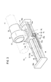
- FIG. 2 is a perspective view of the cable support device 10 shown in FIG. In FIG. 2, the second arm 24 and the cable 11 are indicated by phantom lines in order to facilitate understanding of the configuration of the cable support device 10.
- the cable support device 10 includes a holding unit 52 that holds the cable 11, a linear motion mechanism 54 that allows the holding unit 52 to move along the longitudinal direction of the second arm 24, and the holding unit 52. And a rotation mechanism 56 that enables the second arm 24 to move along the circumferential direction of the second arm 24.
- the holding portion 52 includes a cylindrical member 58 having a hollow portion penetrating in the axial direction, and a support body 60 that supports the cylindrical member 58.
- the cable 11 is inserted into the hollow portion of the cylindrical member 58 and is held so as not to move in the axial direction with respect to the holding portion 52.
- the linear motion mechanism 54 has a long shape as a whole, is disposed along the longitudinal direction of the second arm 24, and supports the holding portion 52 so as to be movable along the longitudinal direction of the second arm 24.
- FIG. 3 is a perspective view showing the configuration of the linear motion mechanism 54. 3 shows a state in which the covers 62a and 62b (see FIG. 2) covering the internal mechanism are removed, and the rotation mechanism 56 is not shown in order to facilitate understanding of the configuration of the linear motion mechanism 54. Omitted.
- the linear motion mechanism 54 is fixed to a base plate (base member) 64, a pair of end plates 66a and 66b provided at both ends in the longitudinal direction of the base plate 64, and the base plate 64.
- a linear motion guide rail 68 extending along the longitudinal direction of the two arms 24, a linear motion slider (linear motion portion) 70 movable along the linear motion guide rail 68, and the linear motion slider 70 at its origin position
- a first urging means 72 that urges elastically toward, a slide member 74 that can move along the linear motion guide rail 68, and a transmission mechanism that moves the slide member 74 in conjunction with the movement of the linear motion slider 70. 76.
- the linear motion slider 70 and the slide member 74 are both guided by the linear motion guide rail 68 and arranged in series so as to be guided on the same track.
- the linear slider 70 and the slide member 74 are elastically urged by the first urging means 72 to be at their respective origin positions (initial positions), but the wrist axis of the robot 12 operates.
- the linear slider 70 fixed to the holding portion 52 is moved in the moving direction of the cable 11 against the urging force of the first urging means 72. Move in the same direction.
- the first urging means 72 of the illustrated configuration example is configured as a gas spring 72A arranged with its longitudinal direction parallel to the extending direction of the linear motion guide rail 68, and its rod portion 78 is attached to the base plate 64.
- the cylinder portion 80 is fixed to the slide member 74.
- the rod portion 78 may be fixed to the end plate 66a.
- the rod portion 78 may be fixed to the slide member 74, and the cylinder portion 80 may be fixed to the base plate 64 or the end plate 66a.
- the first urging means 72 may be another mechanism that exerts an elastic urging force, for example, a mechanism that uses a spring member such as a coil spring, instead of the gas spring 72A.
- the transmission mechanism 76 is configured to move the slide member 74 along the linear motion guide rail 68 by a distance that is smaller than the movement distance of the linear motion slider 70 mechanically interlocking with the movement of the linear motion slider 70.
- the transmission mechanism 76 includes a fixed rack member (first rack member) 82 fixed to the base plate 64 and a movable rack member fixed to the linear slider 70. (Second rack member) 84 and a pinion 86 that meshes with the fixed rack member 82 and the movable rack member 84.
- the fixed rack member 82 is arranged in parallel with the linear motion guide rail 68 and is fixed so as not to move relative to the base plate 64 in the longitudinal direction.
- the fixed rack member 82 is provided with a plurality of teeth 82a along the longitudinal direction, and the teeth 82a and the teeth 86a of the pinion 86 are engaged with each other.
- the movable rack member 84 is disposed in parallel to the linear motion guide rail 68 on the opposite side of the fixed rack member 82 with respect to the pinion 86 and is fixed so as not to move relative to the linear motion slider 70 in the longitudinal direction. Yes.
- a plurality of teeth 84a are formed in the movable rack member 84 along the longitudinal direction, and the teeth 84a and the teeth 86a of the pinion 86 are engaged with each other.
- An interposition member 88 is fixed to the slide member 74, and a pinion 86 is rotatably supported by a shaft portion 89 provided on the interposition member 88.
- the slide member 74, the interposition member 88, and the pinion 86 are integrally movable along the linear motion guide rail 68.
- the linear motion slider 70 moves twice as much as the slide member 74.
- the linear slider 70 and the slide member 74 move against the urging force (elastic force) of the first urging means 72
- the linear slider 70 is not connected to the slide member 74. It is provided in the front.
- the linear slider 70 located in the front in the movement direction has a moving distance than the slide member 74. Since it is long, the distance between them increases, and the linear motion slider 70 and the slide member 74 do not interfere with each other on the linear motion guide rail 68.
- the rotation mechanism 56 includes rotation guide rails 90 and 91 extending along the circumferential direction of the arm, and a rotation slider (rotation unit) movable along the rotation guide rail 90. ) 92, 93 and second urging means 94 for elastically urging the rotary slider 92 toward its origin position (neutral position).
- a plurality of (two in the illustrated example) rotation guide rails 90 and 91 are provided at intervals along the longitudinal direction of the second arm 24.
- Each of the rotation guide rails 90 and 91 has a generally circular ring shape, and is supported by a support bar 50 disposed along the second arm 24 via the attachment members 96 and 97, and the second arm 24.
- the second arm 24 is disposed so as to be spaced a predetermined distance from the outer periphery of the second arm 24.
- a plurality of (two in the illustrated example) rotating sliders 92 and 93 are provided at intervals along the longitudinal direction of the second arm 24, and can slide in the circumferential direction with respect to the respective rotating guide rails 90 and 91. Is arranged.
- FIG. 4 is a schematic view of the rotation guide rail 90 and the rotation slider 92 of the rotation mechanism 56.
- the rotary slider 92 includes a housing 98 and a plurality of (three in the illustrated example) rollers 99 rotatably supported by the housing 98, and is pivotally supported by a shaft portion 98 a provided in the housing 98.
- the roller 99 can move smoothly along the rotation guide rail 90 in the circumferential direction of the second arm 24.
- the plurality of rollers 99 are in contact with the inner peripheral portion of the rotation guide rail 90 (hereinafter referred to as “inner peripheral side roller 99a”). There are some that contact the outer peripheral portion of the rotation guide rail 90 (hereinafter referred to as “outer peripheral roller 99b”), and at least one of the inner peripheral roller 99a and the outer peripheral roller 99b is provided. In the illustrated example, one inner peripheral roller 99a is provided, and two outer peripheral rollers 99b are provided.
- the rotation slider 93 is configured in the same manner as the rotation slider 92.
- the rotation guide rail 90 is provided with a pair of stoppers 100a and 100b that regulate the movable range of the rotation slider 92.
- the stoppers 100 a and 100 b are block-shaped members attached (fixed) to the rotation guide rail 90.
- the rotation slider 92 In FIG. 4, the rotation slider 92 is in the neutral position of the movable range.
- the movement of the rotation slider 92 is restricted at a position in contact with one stopper 100a in the counterclockwise direction, and the other stopper 100b in the clockwise direction. The movement is restricted at the abutting position.
- the stoppers 100a and 100b are configured to be position-adjustable along the extending direction of the rotation guide rail 90 (that is, the circumferential direction of the second arm 24), and by adjusting the positions of the stoppers 100a and 100b, The movable range of the rotary slider 92 can be adjusted to a desired (arbitrary) range.
- the stoppers 100 a and 100 b are provided only on one rotation guide rail 90, but the same stoppers 100 a and 100 b may be provided on the other rotation guide rail 91. Good.
- the second urging means 94 has a circular ring shape as a whole, and is supported and fixed to the support bar 50 via the attachment member 101. More specifically, the second urging means 94 includes a circular ring body 102 disposed so as to surround the arm, and is slidably provided along the ring body 102 and linearly moved. A movable block 104 fixed to the mechanism 54, a plurality of coil springs 106a to 106f arranged in series in a circle along the ring body 102, and intermediate members 108a to 108d arranged between the coil springs 106a to 106f. .
- the ring body 102 is configured by connecting a pipe-like first arc member 110 and a pipe-like second arc member 111 to each other via connecting members 112a and 112b.
- the movable block 104 has a hollow cylindrical shape.
- the ring body 102 is inserted inside the movable block 104.
- the movable block 104 is slidable in the circumferential direction along the ring body 102 using the ring body 102 as a guide, and is fixed to the base plate 64 of the linear motion mechanism 54.
- the movable block 104, the linear motion mechanism 54, and the holding unit 52 are integrally movable along the ring body 102 in the circumferential direction.
- the plurality of coil springs 106 a to 106 f have a ring body 102 inserted through them, and are arranged elastically extendable along the ring body 102.
- the plurality of intermediate members 108a to 108d have a hollow cylindrical shape, and the ring body 102 is inserted inside the intermediate members 108a to 108d, and is sandwiched between the coil springs 106a to 106f. It can slide in the circumferential direction.
- the movable block 104 is urged clockwise in FIG. 5 by the coil springs 106a to 106c on one side and counterclockwise in FIG. 5 by the coil springs 106d to 106f on the other side. Therefore, when the holding portion 52 does not receive an external force in the circumferential direction, the urging force (elastic force) of the coil springs 106a to 106c on one side and the urging force (elastic force) of the coil springs 106d to 106f on the other side.
- the movable block 104 is held at a position where the two are balanced.
- the movable block 104 moves counterclockwise against the biasing force of the coil springs 106a to 106c on one side. At this time, the coil springs 106a to 106c on one side are elastically compressed, and the intermediate members 108a and 108b disposed between the coil springs 106a to 106c also move counterclockwise.
- the holding portion 52 receives the clockwise force in FIG. 5
- the movable block 104 moves clockwise against the urging force of the coil springs 106d to 106f on the other side. At this time, the other coil springs 106d to 106f are elastically compressed, and the intermediate members 108c and 108d disposed between the coil springs 106d to 106f also move in the clockwise direction.
- the cable support device 10 is basically configured as described above, and the operation and effect will be described below.
- the holding portion 52 is moved in the longitudinal direction and the circumferential direction of the arm by the linear motion mechanism 54 and the rotation mechanism 56.
- the linear motion slider 70 is the first biasing means 72. It is guided by the linear guide rail 68 against the elastic force of the second arm 24 and moves in the direction of the distal end of the second arm 24. As the linear slider 70 moves, the holding portion 52 also moves (advances) in the distal direction of the second arm 24.
- the holding mechanism 52 follows the cable 11 that is moved by the operation (posture change) of the wrist 26 of the robot 12 in the longitudinal direction and the circumferential direction of the arm 21 by the linear movement mechanism 54 and the rotation mechanism 56. Since it moves, it is possible to sufficiently follow the degree of freedom of the wrist portion 26 of the robot 12 without increasing the slack of the cable 11 and without increasing the stroke of the holding portion 52.
- the same tension can always be applied to the cable 11 for various movements of the wrist portion 26 of the robot 12 and the slack of the cable 11 can be restricted, so that the reproducibility of the position of the cable 11 can be improved.
- the minimum bending angle of the cable 11 increases, damage to the cable 11 can be reduced, and the life of the cable 11 can be extended.
- the holding portion 52 is supported by the linear motion mechanism 54 so as to be movable in the longitudinal direction of the second arm 24, and the linear motion mechanism 54 is supported by the rotation mechanism 56.
- the holding portion 52 and the linear motion mechanism 54 are configured to be movable in the circumferential direction of the second arm 24 integrally. Therefore, a mechanism for moving the holding portion 52 in the longitudinal direction and the circumferential direction of the second arm 24 is realized with a simple configuration.
- the first urging means 72 urges the linear slider 70 toward the origin position
- the second urging means 94 urges the rotary slider 92 toward the origin position.
- the movable range of the rotation slider 92 is limited to a predetermined range by providing the rotation guide rail 90 with the stoppers 100a and 100b.
- the movable range of the rotary slider 92 is preferably about plus or minus 100 degrees around the origin, for example. If the movement range of the rotary slider 92 is too large, there is a concern that the cable 11 will not return to the initial arrangement position, but the movable range of the rotary slider 92 is limited to a predetermined range as in this embodiment. Thus, the reproducibility of the cable 11 can be ensured.
- the gas spring 72A is employed as the first urging means 72, it is possible to easily adjust the gas pressure to an optimum tension according to the individuality (movement characteristics, etc.) of the robot 12. Can be adjusted. Further, since the gas spring 72A has a low spring constant and a substantially constant tension is applied, the change in tension applied to the cable 11 can be reduced.
- the movement of the first urging means 72 attached to the slide member 74 with respect to the movement distance of the linear motion slider 70 to which the holding portion 52 is attached by the action of the transmission mechanism 76 (see FIG. 3) Since the distance is shortened, the spring constant of the linear motion mechanism 54 as a whole is correspondingly smaller than the spring constant of the first urging means 72 itself. Therefore, the change in tension applied to the cable 11 can be reduced, and the load on the cable 11 can be made constant, so that the life of the cable 11 can be further improved.
- the expansion / contraction length of the biasing means 72 is a half, but instead of such a pinion 86, if a pinion having large and small tooth portions (small gear portion and large gear portion) having different numbers of teeth is used, It can be easily reduced to, for example, a third or a quarter. In this case, the fixed rack member 82 and the small gear portion may be engaged with each other, and the movable rack member 84 and the large gear portion may be engaged with each other.
- the second urging means 94 has a configuration in which a plurality of intermediate members 108a to 108d are disposed between the plurality of coil springs 106a to 106f, whereby the coil springs 106a to 106f Since expansion and contraction and movement are performed smoothly, the movable block 104 can be moved smoothly along the ring body 102. Therefore, the movable block 104 can be urged stably regardless of the position of the movable block 104, and a tension can be stably applied to the cable 11 via the holding portion 52.
- the cable support device 10 since the cable support device 10 is installed on the second arm 24, it is easy to follow the movement of the wrist portion 26 of the robot 12, and the minimum bending radius of the cable 11 can be increased. Therefore, damage to the cable 11 can be further reduced, and the life of the cable 11 can be more effectively extended.
- the cable support device 10 is not directly attached to the arm body 24 b of the second arm 24, and is supported by the support portion 46 fixed to the base end portion 24 a of the second arm 24, whereby the arm body. Since it is arranged along 24b, the cable support device 10 can be easily provided as an additional equipment for the existing robot 12.
- the origins of the linear motion mechanism 54 and the rotation mechanism 56 are set at the midpoint of the operating range of the wrist portion 26 of the robot 12.
- the linear motion slider 70 of the linear motion mechanism 54 is at its origin position (the position of the linear motion slider shown in FIG. 3) and
- the rotary sliders 92 and 93 of the moving mechanism 56 are at their origin positions (positions of the rotary sliders 92 and 93 shown in FIGS. 2 and 4).
- the operation range of the wrist 26 specifically means the operation ranges of the fourth drive shaft a4, the fifth drive shaft a5, and the sixth drive shaft a6.
- the “operation range” here is not a movable range on the mechanism of the fourth drive shaft a4, the fifth drive shaft a5, and the sixth drive shaft a6, but when performing work scheduled for the robot 12.
- the fourth drive shaft a4, the fifth drive shaft a5, and the sixth drive shaft a6 move within a range.
- each origin of the linear motion mechanism 54 and the rotation mechanism 56 is set to an intermediate point of the operating range of the wrist portion 26 of the robot 12.
- the operation range of the wrist portion 26 of the robot 12 with respect to the respective origins becomes uniform, and the range following the operation of the wrist portion 26 of the robot 12 can be minimized. Therefore, the required stroke of the linear motion mechanism 54 and the rotation mechanism 56 can be minimized, and the cable support device 10 can be easily mounted on the robot 12.
- the support body 46 extends from the base end portion 24a along the arm main body 24b so as not to be affected by the rotation of the arm main body 24b rotatable about the fourth drive shaft a4.
- the cable support device 10 may be directly attached to the arm body 24b as in the attachment structure 118 shown in FIGS.
- the first wrist element 30 is rotatable about the fourth drive shaft a4 along the axial direction of the arm body 24b.
- the attachment structure 118 includes ring-shaped belt members 120 and 122 fixed to the arm main body 24b, and rotates around the outer peripheral portion of the arm main body 24b via support blocks 124 and 126 fixed to the belt members 120 and 122.
- the rotation guide rails 90 and 91 are supported in a state where a gap is left between the movement guide rails 90 and 91, respectively.
- the rotary sliders 92 and 93 are movable along the rotary guide rails 90 and 91 in a state where the rotary sliders 92 and 93 are lifted from the arm main body 24b.
- the two support blocks 124 are provided at intervals in the circumferential direction of the belt members 120 and 122, but may be a member in which these are integrated. The same applies to the support block 126.
- the belt members 120 and 122 support the second urging means 94 with a gap between the outer peripheral portion of the arm body 24 b and the second urging means 94 via the support block 128.
- the movable block 104 (see FIG. 5) of the second urging means 94 is movable along the ring body 102 in a state of floating from the arm main body 24b.
- the support block 128 is provided at a position (position shifted by 180 °) opposite to the neutral position of the rotary slider 93 with reference to the arm body 24b.
- the cable support device 10 can be attached to the second arm 24 with higher rigidity than in the case of a long structure such as the support portion 46.
- the linear motion mechanism 54 is disposed above the second arm 24. Instead of such a configuration, the linear motion mechanism 54 is disposed below or on the side of the second arm 24. Also good.
- the arrangement position of the linear motion mechanism 54 with respect to the second arm 24 can be arbitrarily set according to the individuality of the robots 12 and 12a (for example, the operating range of the wrist portion 26).
Landscapes
- Engineering & Computer Science (AREA)
- Mechanical Engineering (AREA)
- Robotics (AREA)
- Manipulator (AREA)
Abstract
ケーブル支持装置(10)は、ケーブル(11)を保持する保持部(52)と、第2アーム(24)の長手方向に沿って移動自在な直動スライダ(70)を有する直動機構(54)と、第2アーム(24)の周方向に沿って回転自在な回動スライダ(92、93)を有する回動機構(56)とを備える。直動機構(54)及び回動機構(56)により、保持部(52)が第2アーム(24)の長手方向及び周方向に変位自在となっている。
Description
本発明は、ロボットのアームを経由し、ロボットの手首先端に設けられたエンドエフェクタに繋がるケーブルを支持及び案内するケーブル支持装置に関する。
例えば、自動車の製造工程では、ロボット(産業用ロボット)を用いてワークを抵抗溶接することが行われている。そのようなロボットは、多関節アームを有し、当該アームの手首先端にはエンドエフェクタとしての溶接ハンドが設けられている。当該溶接ハンドには、ロボットのアームを経由してケーブルが接続されている。
ケーブルがロボットに隣接する機器に干渉したり、ケーブルがアームに巻き付いて断線したりすることを防止するために、ケーブル支持装置がロボットに装備される。従来、ケーブル支持装置として、ケーブルを保持する保持部をロボットのアームの長手方向に沿って移動自在に設け、ケーブルの張りやたるみを調整するように構成したものがある(例えば、実開平3-103193号公報を参照)。
従来のケーブル支持装置において、ロボット手首の自由度に追従させるためには、ケーブルを長くして大きなたるみを持たせるか、保持部のストローク長さを十分にとる必要がある。しかしながら、ケーブルを大きくたるませると、ロボットの先端にあるエンドエフェクタの作業エリア周辺の治具やワークに干渉しやすくなる。また、保持部のストロークを十分にとると、ロボットのアーム上に装備できる実用長さを大きく超えてしまうという問題がある。
本発明はこのような課題を考慮してなされたものであり、ケーブルのたるみを大きくすることなく且つ保持部のストロークを長大化することなく、ロボット手首の自由度に十分に追従させることができるケーブル支持装置を提供することを目的とする。
上記の目的を達成するため、本発明は、ロボットのアームを経由し、ロボットの手首部の先端に設けられたエンドエフェクタに繋がるケーブルを支持及び案内するケーブル支持装置であって、前記ケーブルを保持する保持部と、前記アームの長手方向に沿って移動自在な直動部を有する直動機構と、前記アームの周方向に沿って回転自在な回動部を有する回動機構とを備え、前記直動機構及び前記回動機構により、前記保持部が前記アームの長手方向及び周方向に変位自在となっていることを特徴とする。
上記の構成によれば、直動機構及び回動機構により、保持部が、ロボットの手首部の動作(姿勢変更)によって移動するケーブルに追従してアームの長手方向及び周方向に動くので、ケーブルのたるみを大きくすることなく且つ保持部のストロークを長大化することなく、ロボット手首の自由度に十分に追従させることができる。また、ロボットの手首部の種々の動作に対して、いつも同じテンションをケーブルに与え、かつ、ケーブルのたるみを規制でき、よって、ケーブルの位置の再現性を高めることができる。そして、これにより、ケーブルの最小曲げ角度が大きくなり、ケーブルの損傷を低減でき、ケーブルの寿命を延ばすことができる。
上記のケーブル支持装置において、前記保持部は、前記直動機構の直動部に取り付けられ、前記直動機構は、前記回動機構の回動部に取り付けられ、前記保持部と一体的に前記アームの周方向に沿って回動自在であるとよい。
このように、直動機構を回動機構で支持する構成を採用することにより、ロボットのアームの長手方向及び周方向に可動な機構を、ロボットのアームに容易に装備することができる。
上記のケーブル支持装置において、前記直動機構は、前記アームの長手方向に沿って延在する直動ガイドレールと、前記直動ガイドレールに沿って移動可能な前記直動部である直動スライダと、前記直動スライダをその原点位置に向けて弾性的に付勢する第1付勢手段とを有し、前記回動機構は、前記アームの周方向に沿って延在する回動ガイドレールと、前記回動ガイドレールに沿って移動可能な前記回動部である回動スライダと、前記回動スライダをその原点位置に向けて弾性的に付勢する第2付勢手段とを有するとよい。
このように、第1付勢手段により直線スライダを原点位置に向けて付勢するとともに、第2付勢手段により回動スライダを原点位置に向けて付勢することにより、ロボットの手首部の動作位置及び姿勢に応じてケーブルの位置が一義的に決まるので、ケーブルの再現性を一層向上できる。
上記のケーブル支持装置において、前記直動機構は、前記直動ガイドレールに沿って移動自在であり前記第1付勢手段に連結されたスライド部材と、前記直動スライダの移動に機械的に連動して前記直動スライダの移動距離よりも少ない距離だけ前記スライド部材を前記直動ガイドレールに沿って移動させる伝達機構とを有するとよい。
これにより、保持部が取り付けられた直動スライダの移動距離に対して、スライド部材に取り付けられた第1付勢手段の移動距離が短くなるため、その分、直動機構全体としてのばね定数は、第1付勢手段自体のばね定数よりも小さくなる。したがって、ケーブルに与えるテンションの変化を小さくでき、これによりケーブルに対する負荷を一定化できるので、ケーブルの寿命を一層向上できる。
上記のケーブル支持装置において、前記第2付勢手段は、前記アームを囲むように配置されたリング体と、前記リング体に沿って摺動可能に設けられ、前記直動機構に固定された可動ブロックと、前記リング体に沿って円形をなすように直列配置された複数のコイルスプリングと、前記複数のコイルスプリング間に配置された中間部材とを有するとよい。
このように、複数のコイルプリング間に中間部材を配置したことで、コイルスプリングの伸縮がスムーズに行われるので、可動ブロックをリング体に沿ってスムーズに移動させることができる。よって、可動ブロックの位置に関わらず、可動ブロックを安定的に付勢することができ、保持部を介してケーブルに安定的にテンションを与えることができる。
上記のケーブル支持装置において、前記直動機構及び前記回動機構の原点は、前記ロボットの前記手首部の作動範囲の中間点であるとよい。
これにより、直動機構及び回動機構の原点を基準としたロボットの作動範囲が均等になり、ロボット軸に追従する範囲を最小にすることができる。これにより、直動機構及び回動機構の必要ストロークを最小とすることができ、ロボットへのケーブル支持装置の搭載が容易となる。
上記のケーブル支持装置において、前記アームは、第1アームと、前記第1アームの先端に回動自在に連結された第2アームとを有し、前記手首部は前記第2アームの先端に設けられ、前記ケーブル支持装置は、前記第2アームに設置されるとよい。
これにより、ロボットの手首部の動きに追従しやすくなり、ケーブルの最小曲げ半径を大きくできるため、ケーブルの損傷をより低減でき、ケーブルの寿命を一層効果的に延ばすことができる。
上記のケーブル支持装置において、前記アームは、回動可能に支持された基端部と、前記基端部から延出するアーム本体とを有し、前記ケーブル支持装置は、前記基端部に固定された支持部によって支持されることで前記アーム本体に沿って配置されるとよい。
これにより、既存のロボットに対して追加装備として、簡単にケーブル支持装置を備え付けることができる。
本発明のケーブル支持装置によれば、ケーブルのたるみを大きくすることなく且つ保持部のストロークを長大化することなく、ロボット手首の自由度に十分に追従させることができる。
以下、本発明に係るケーブル支持装置について好適な実施の形態を挙げ、添付の図面を参照しながら説明する。
図1は、本発明の一実施形態に係るケーブル支持装置10を備えたロボット12の側面図である。図示した構成例のロボット12は、自動車の製造工程で抵抗溶接を行うロボット12して構成されたものであり、ロボット本体14と、このロボット本体14に取り付けられた溶接ハンド(溶接ガン)16とを有する。
ロボット本体14は、ベース台18と、鉛直な第1駆動軸a1を中心としてベース台18に回動可能に支持された旋回部20と、旋回部20に回動可能に支持されたアーム21と、アーム21の先端に設けられ3自由度を有する手首部26と、ケーブル11を支持及び案内するケーブル支持装置10とを備える。
ロボット本体14は、6つの駆動軸(第1~第6駆動軸a1~a6)を有する多関節ロボットであり、アーム及び手首部26の動作により、3次元空間上で手首部26の先端(溶接ハンド16)の位置及び姿勢を変化させる。ロボット12は、制御装置28と通信可能であって、当該制御装置28は、6つの駆動軸を数値制御して、3次元空間上で手首部26の先端の位置及び姿勢を制御する。
アーム21は、水平な第2駆動軸a2を中心として旋回部20に回動可能に支持された第1アーム22と、水平な第3駆動軸a3を中心として第1アーム22に回動可能に支持された第2アーム24とを有する。第1アーム22は、第2駆動軸a2によって動作し、主として前後方向に揺動するアームである。第2アーム24は、第3駆動軸a3によって動作し、主として上下方向に揺動するアームであり、第3駆動軸a3で回動可能に支持された基端部24aと、当該基端部24aから延出するアーム本体24bとを有する。アーム本体24bは、アーム本体24bの長手方向(軸線方向)に延在する第4駆動軸a4を中心として基端部24aに回動可能に連結されている。
ロボット本体14の第2駆動軸a2及び第3駆動軸a3は、第1駆動軸a1と直交する方向の駆動軸であり、第2駆動軸a2と第3駆動軸a3は互いに平行である。第1~第3駆動軸a1~a3の動作により、第2アーム24先端の位置及び姿勢が決められる。
ロボット本体14の手首部26は、第2アーム24に支持された第1手首要素30と、第4駆動軸a4に直交する方向に延在する第5駆動軸(第1手首駆動軸)a5を中心として第1手首要素30に回動可能に支持された第2手首要素32と、第2手首要素32の長手方向(軸線方向)に延在する第6駆動軸(第2手首駆動軸)a6を中心として第3手首要素34に回動可能に支持された第3手首要素34とを有する。
溶接ハンド16は、手首部26の先端部に取り付けられている。具体的には、溶接ハンド16は、接続ユニット36を介して第3手首要素34に着脱可能に接続されており、第3手首要素34と一体となって第6駆動軸a6を中心として回動する。溶接ハンド16は、基部38と、基部38に開閉可能に設けられた一対のアーム部材40a、40bと、一対のアーム部材40a、40bの先端にそれぞれ設けられた電極チップ(溶接電極)42a、42bと、基部に設けられて一対のアーム部材40a、40bを開閉する駆動機構43とを有する。
上記のように構成されたロボット12では、制御装置28による制御作用下に、ロボット本体14を駆動して、溶接ハンド16の位置及び姿勢を制御するとともに、電極チップ42a、42bでワークを挟持し、その後、電極チップ42a、42b間に通電することで、ワークを抵抗溶接できる。
ケーブル11は、手首部26に設けられたサブ保持部44にて保持されるとともに、第2アーム24に設けられたケーブル支持装置10にて支持されている。ケーブル11は柔軟性を有する円筒形状であり、ケーブル11の内部には、図示しない溶接電源から電極チップ42a、42bに至る、電力を供給するための配線、制御装置28から駆動機構43に至る、駆動機構43を制御するための配線などがまとめて収容されている。
ケーブル支持装置10は、ロボット12のアーム21(具体的には、第2アーム24)を経由し、ロボット12の手首先端に設けられたエンドエフェクタである溶接ハンド16に繋がるケーブル11を支持及び案内するものであり、支持部46を介して第2アーム24に装備され(取り付けられ)ている。支持部46は、第2アーム24の基端部24aに固定されたブラケット48と、当該ブラケット48に固定され第2アーム24のアーム本体24bに沿って延出する支持バー50とを有し、ケーブル支持装置10は支持バー50で支持されている。
図2は、図1に示すケーブル支持装置10の斜視図である。なお、図2では、ケーブル支持装置10の構成の理解を容易にするため、第2アーム24及びケーブル11を仮想線で示している。図2に示すように、ケーブル支持装置10は、ケーブル11を保持する保持部52と、保持部52を第2アーム24の長手方向に沿って移動可能にする直動機構54と、保持部52を第2アーム24の周方向に沿って移動可能にする回動機構56とを有する。
保持部52は、軸線方向に貫通した中空部を有する円筒部材58と、円筒部材58を支持する支持体60とを有する。ケーブル11は、円筒部材58の中空部に挿通されて、保持部52に対して軸線方向に移動しないように保持されている。
直動機構54は、全体として長尺状をなし、第2アーム24の長手方向に沿って配置され、保持部52を第2アーム24の長手方向に沿って移動可能に支持している。図3は、直動機構54の構成を示す斜視図である。なお、図3では、直動機構54の構成の理解を容易にするため、内部機構を覆うカバー62a、62b(図2参照)を取り外した状態を示し、かつ、回動機構56については図示を省略している。
図3に示すように、直動機構54は、ベースプレート(ベース部材)64と、このベースプレート64の長手方向の両端に設けられた一対の端部プレート66a、66bと、ベースプレート64に固定され、第2アーム24の長手方向に沿って延在する直動ガイドレール68と、直動ガイドレール68に沿って移動可能な直動スライダ(直動部)70と、直動スライダ70をその原点位置に向けて弾性的に付勢する第1付勢手段72と、直動ガイドレール68に沿って移動可能なスライド部材74と、直動スライダ70の移動に連動してスライド部材74を移動させる伝達機構76とを有する。
図示した構成例において、直動スライダ70及びスライド部材74は、共に直動ガイドレール68に案内され、同一軌道上で案内されるように直列に配置されている。図2において、直動スライダ70及びスライド部材74は、第1付勢手段72によって弾性的に付勢されることで、それぞれの原点位置(初期位置)にあるが、ロボット12の手首軸が動作してケーブル11が図2で左方向に引っ張られることに伴って、第1付勢手段72の付勢力に抗して、保持部52に固定された直動スライダ70がケーブル11の移動方向と同じ方向に移動する。
図示した構成例の第1付勢手段72は、その長手方向を直動ガイドレール68の延在方向と平行にして配置されたガススプリング72Aとして構成されており、そのロッド部78がベースプレート64に固定され、そのシリンダ部80が、スライド部材74に固定されている。ロッド部78は端部プレート66aに固定されてもよい。図示した構成例とは逆に、ロッド部78がスライド部材74に固定され、シリンダ部80がベースプレート64又は端部プレート66aに固定されてもよい。第1付勢手段72としては、ガススプリング72Aに代えて、弾性的な付勢力を発揮する他の機構、例えば、コイルスプリング等のバネ部材を用いた機構であってもよい。
伝達機構76は、直動スライダ70の移動に機械的に連動して直動スライダ70の移動距離よりも少ない距離だけスライド部材74を直動ガイドレール68に沿って移動させるように構成されている。図示例の構成に即して、より具体的に説明すると、伝達機構76は、ベースプレート64に固定された固定ラック部材(第1ラック部材)82と、直動スライダ70に固定された可動ラック部材(第2ラック部材)84と、固定ラック部材82及び可動ラック部材84と噛み合うピニオン86とを有する。
固定ラック部材82は、直動ガイドレール68と平行に配置され、ベースプレート64に対して長手方向に相対移動しないように固定されている。固定ラック部材82には、長手方向に沿って複数の歯82aが刻設されており、当該歯82aとピニオン86の歯86aとが噛み合っている。
可動ラック部材84は、直動ガイドレール68と平行に、ピニオン86に対して固定ラック部材82とは反対側に配置され、直動スライダ70に対して長手方向に相対移動しないように固定されている。可動ラック部材84には、長手方向に沿って複数の歯84aが刻設されており、当該歯84aとピニオン86の歯86aとが噛み合っている。
スライド部材74には、介在部材88が固定されており、当該介在部材88に設けられた軸部89にてピニオン86が回転自在に支持されている。スライド部材74、介在部材88及びピニオン86は、一体となって、直動ガイドレール68に沿って移動可能である。
上記のように構成された直動機構54において、直動スライダ70が直動ガイドレール68に沿って移動するとき、直動スライダ70に固定された可動ラック部材84も一緒に移動する。そうすると、可動ラック部材84と噛み合うピニオン86は、これを軸支する介在部材88とともに、回転しながら直動スライダ70の移動方向と同じ方向に移動するが、このときの介在部材88及びスライド部材74の移動量は、直動スライダ70の移動量の半分である。
換言すれば、直動スライダ70は、スライド部材74に対して2倍の距離を移動する。直動スライダ70及びスライド部材74が第1付勢手段72の付勢力(弾性力)に抗して移動するときの移動方向(図2で左方向)に関して、直動スライダ70はスライド部材74の前方に設けられている。これにより、直動スライダ70及びスライド部材74が第1付勢手段72の付勢力に抗して移動するとき、移動方向の前方にある直動スライダ70のほうが、スライド部材74よりも移動距離が長いので、両者の距離が広がり、直動ガイドレール68上で直動スライダ70とスライド部材74とが干渉することがない。
次に、回動機構56の構成を説明する。図2に示すように、回動機構56は、アームの周方向に沿って延在する回動ガイドレール90、91と、回動ガイドレール90に沿って移動可能な回動スライダ(回動部)92、93と、回動スライダ92をその原点位置(中立位置)に向けて弾性的に付勢する第2付勢手段94とを有する。
本実施形態において、回動ガイドレール90、91は第2アーム24の長手方向に沿って間隔を置いて複数(図示例では、2つ)設けられている。各回動ガイドレール90、91は、全体的に円形のリング状であり、取付部材96、97を介して、第2アーム24に沿って配設された支持バー50によって支持され、第2アーム24の外周部から所定間隔を空けた状態で、第2アーム24を囲んで配置されている。
回動スライダ92、93は、第2アーム24の長手方向に沿って間隔を置いて複数(図示例では、2つ)設けられ、各回動ガイドレール90、91に対して周方向に摺動可能に配置されている。
図4は、回動機構56の回動ガイドレール90及び回動スライダ92の概略図である。回動スライダ92は、ハウジング98と、ハウジング98に回転自在に支持された複数(図示例では、3つ)のローラ99とを有し、ハウジング98に設けられた軸部98aよって軸支されたローラ99が転動することにより回動ガイドレール90に沿って第2アーム24の周方向にスムーズに移動できるようになっている。
回動スライダ92の、回動ガイドレール90に対する姿勢を保持するために、複数のローラ99は、回動ガイドレール90の内周部に接するもの(以下、「内周側ローラ99a」という)と、回動ガイドレール90の外周部に接するもの(以下、「外周側ローラ99b」という)とがあり、内周側ローラ99aと外周側ローラ99bのうち少なくとも一方は、複数設けられる。図示例では、内周側ローラ99aは1つ設けられ、外周側ローラ99bは2つ設けられている。回動スライダ93も、回動スライダ92と同様に構成されている。
回動ガイドレール90には、回動スライダ92の可動範囲を規制する一対のストッパ100a、100bが設けられている。ストッパ100a、100bは、回動ガイドレール90に取り付けられた(固定された)ブロック状の部材である。図4において、回動スライダ92は、可動範囲の中立位置にあり、同図で反時計回り方向に関しては一方のストッパ100aに当接する位置で移動が規制され、時計方向に関しては他方のストッパ100bに当接する位置で移動が規制される。
ストッパ100a、100bは、回動ガイドレール90の延在方向(すなわち、第2アーム24の周方向)に沿って位置調整可能に構成されており、ストッパ100a、100bの位置調整をすることで、回動スライダ92の可動範囲を所望の(任意の)範囲に調整することができる。なお、図2に示す構成例では、ストッパ100a、100bは、一方の回動ガイドレール90のみに設けられているが、他方の回動ガイドレール91にも同様のストッパ100a、100bを設けてもよい。
図5に示すように、第2付勢手段94は、全体的に円形のリング状であり、取付部材101を介して支持バー50に支持及び固定されている。図示例に即してより詳細に説明すると、第2付勢手段94は、アームを囲むように配置された円形のリング体102と、リング体102に沿って摺動可能に設けられて直動機構54に固定された可動ブロック104と、リング体102に沿って円形に直列配置された複数のコイルスプリング106a~106fと、コイルスプリング106a~106f間に配置された中間部材108a~108dとを有する。
リング体102は、パイプ状の第1円弧部材110と、パイプ状の第2円弧部材111とが、接続部材112a、112bを介して互いに連結して構成されたものである。可動ブロック104は、中空円筒形をなし、その内側にリング体102が挿通され、リング体102をガイドとしてリング体102に沿って周方向にスライド自在であり、直動機構54のベースプレート64に固定されている。可動ブロック104、直動機構54及び保持部52は、一体となってリング体102に沿って周方向に移動可能である。
複数のコイルスプリング106a~106fは、それらの内側にリング体102が挿通され、リング体102に沿って弾性的に伸縮可能に配設されている。複数の中間部材108a~108dは、中空円筒形をなし、その内側にリング体102が挿通され、コイルスプリング106a~106f間に挟持された状態で、リング体102をガイドとしてリング体102に沿って周方向にスライド可能である。
可動ブロック104は、一方側のコイルスプリング106a~106cにより図5で時計方向に付勢され、他方側のコイルスプリング106d~106fにより図5で半時計方向に付勢される。よって、保持部52が周方向の外力を受けていないときは、一方側のコイルスプリング106a~106cの付勢力(弾発力)と他方側のコイルスプリング106d~106fの付勢力(弾発力)とがバランスした位置で、可動ブロック104が保持される。
保持部52が図5で半時計方向の力を受けると、可動ブロック104は、一方側のコイルスプリング106a~106cの付勢力に抗して半時計方向に移動する。このとき、一方側のコイルスプリング106a~106cは、弾性的に圧縮されるとともに、コイルスプリング106a~106c間に配置された中間部材108a、108bも半時計方向に移動する。一方、保持部52が図5で時計方向の力を受けたとき、可動ブロック104は、他方側のコイルスプリング106d~106fの付勢力に抗して時計方向に移動する。このとき、他方側のコイルスプリング106d~106fは、弾性的に圧縮されるとともに、コイルスプリング106d~106f間に配置された中間部材108c、108dも時計方向に移動する。
本実施形態に係るケーブル支持装置10は、基本的には以上のように構成されるものであり、以下、その作用及び効果について説明する。
ロボット12の手首部26が動作し、これに伴ってケーブル11が引っ張られると、直動機構54及び回動機構56により、保持部52がアームの長手方向及び周方向に動く。例えば、ロボット12の手首部26が第5駆動軸a5を中心として屈曲し、ケーブル11が図1で左方向に引っ張られると、直動機構54において、直動スライダ70が第1付勢手段72の弾発力に抗して直動ガイドレール68によって案内されて第2アーム24の先端方向に移動する。この直動スライダ70の移動に伴って、保持部52も第2アーム24の先端方向に移動する(前進する)。
また、ロボット12の手首部26が第4駆動軸a4、第6駆動軸a6の一方又は両方で回転し、ケーブル11が第2アーム24の周方向に引っ張られると、回動機構56において、回動スライダが第2付勢手段94の弾発力に抗して回動ガイドレール90によって案内されて周方向に移動する。この回動スライダ92の移動に伴って、保持部52も第2アーム24の周方向に移動する。
このように、直動機構54及び回動機構56により、保持部52が、ロボット12の手首部26の動作(姿勢変更)によって移動するケーブル11に追従してアーム21の長手方向及び周方向に動くので、ケーブル11のたるみを大きくすることなく且つ保持部52のストロークを長大化することなく、ロボット12の手首部26の自由度に十分に追従させることができる。
また、ロボット12の手首部26の種々の動作に対して、いつも同じテンションをケーブル11に与え、かつ、ケーブル11のたるみを規制でき、よって、ケーブル11の位置の再現性を高めることができる。そして、これにより、ケーブル11の最小曲げ角度が大きくなり、ケーブル11の損傷を低減でき、ケーブル11の寿命を延ばすことができる。
上述したように、本実施形態では、保持部52を直動機構54で支持して第2アーム24の長手方向に移動自在とし、このような直動機構54を回動機構56で支持し、保持部52及び直動機構54を一体的に第2アーム24の周方向に移動自在に構成している。このため、第2アーム24の長手方向及び周方向に保持部52を可動にする機構を、簡単な構成で実現している。
また、本実施形態では、第1付勢手段72により直動スライダ70を原点位置に向けて付勢するとともに、第2付勢手段94により回動スライダ92を原点位置に向けて付勢することにより、ロボット12の手首部26の動作位置及び姿勢に応じてケーブル11の位置が一義的に決まるので、ケーブル11の再現性をより向上できる。
さらに、本実施形態では、回動ガイドレール90にストッパ100a、100bを設けることで、回動スライダ92の可動範囲を所定範囲に制限している。回動スライダ92の可動範囲は、例えば、原点を中心にプラスマイナス100°程度がよい。回動スライダ92の移動範囲を大きくし過ぎると、ケーブル11が初期の配置位置に戻らなくなることが懸念されるが、本実施形態のように回動スライダ92の可動範囲を所定範囲に制限することで、ケーブル11の再現性を確保できる。
本実施形態では、第1付勢手段72としてガススプリング72Aを採用しているので、ガス圧を調整することにより、ロボット12の個性(動きの特性等)に応じて、最適なテンションに容易に調整することができる。また、ガススプリング72Aは、ばね定数が低く、ほぼ一定のテンションがかけられるため、ケーブル11に与えるテンションの変化を小さくできる。
本実施形態では、伝達機構76(図3参照)の作用により、保持部52が取り付けられた直動スライダ70の移動距離に対して、スライド部材74に取り付けられた第1付勢手段72の移動距離が短くなるため、その分、直動機構54全体としてのばね定数は、第1付勢手段72自体のばね定数よりも小さくなる。したがって、ケーブル11に与えるテンションの変化を小さくでき、これによりケーブル11に対する負荷を一定化できるので、ケーブル11の寿命を一層向上できる。
なお、図3に示した伝達機構76では、固定ラック部材82と可動ラック部材84が同一のピニオン86と噛み合っているため、直動スライダ70の移動距離に対するスライド部材74の移動距離(第1付勢手段72の伸縮長さ)は2分の1であるが、このようなピニオン86に代えて、歯数の異なる大小の歯部(小ギア部及び大ギア部)を有するピニオンを用いれば、容易に例えば3分の1、4分の1にすることができる。この場合、固定ラック部材82と小ギア部とを噛み合わせ、可動ラック部材84と大ギア部とを噛み合わせればよい。
本実施形態において、第2付勢手段94(図5参照)は、複数のコイルスプリング106a~106f間に複数の中間部材108a~108dを配置した構成を有し、これによりコイルスプリング106a~106fの伸縮及び移動がスムーズに行われるので、可動ブロック104をリング体102に沿ってスムーズに移動させることができる。よって、可動ブロック104の位置に関わらず、可動ブロック104を安定的に付勢することができ、保持部52を介してケーブル11に安定的にテンションを与えることができる。
本実施形態では、ケーブル支持装置10は第2アーム24に設置されているため、ロボット12の手首部26の動きに追従しやすくなり、ケーブル11の最小曲げ半径を大きくできる。よって、ケーブル11の損傷をより低減でき、ケーブル11の寿命を一層効果的に延ばすことができる。
本実施形態では、ケーブル支持装置10が第2アーム24のアーム本体24bに直接取り付けられておらず、第2アーム24の基端部24aに固定された支持部46によって支持されることでアーム本体24bに沿って配置されているので、既存のロボット12に対して追加装備として、簡単にケーブル支持装置10を備え付けることができる。
本実施形態では、直動機構54及び回動機構56の原点は、ロボット12の手首部26の作動範囲の中間点に設定されている。換言すれば、ロボット12の手首部26がその作動範囲の中間点にあるとき、直動機構54の直動スライダ70がその原点位置(図3に示す直動スライダの位置)にあるとともに、回動機構56の回動スライダ92、93がその原点位置(図2及び図4に示す回動スライダ92、93の位置)にある。
ここで、手首部26の作動範囲とは、具体的には、第4駆動軸a4、第5駆動軸a5及び第6駆動軸a6の作動範囲を意味する。また、ここでいう「作動範囲」とは、第4駆動軸a4、第5駆動軸a5及び第6駆動軸a6の機構上の可動範囲ではなく、ロボット12に予定されている作業を実行する際の第4駆動軸a4、第5駆動軸a5及び第6駆動軸a6が動く範囲を意味する。
ロボット12の初期位置(ロボット12のシステムが停止しているときの位置)とロボット12の作動範囲の中間点が一致していない場合、ロボット12の初期位置に直動機構54及び回動機構56の原点を合わせると、当該原点を基準としたロボット12の作動範囲に偏りが発生する。このため、ケーブル支持装置10がケーブル11に追従するために必要とされる可動範囲が大きくなる。
すなわち、直動機構54及び回動機構56の必要ストロークが大きくなるので、ロボット12への搭載が困難となる場合がある。そこで、本実施形態では、直動機構54と回動機構56の各原点を、ロボット12の手首部26の作動範囲の中間点に設定している。これにより、それぞれの原点を基準としたロボット12の手首部26の作動範囲が均等になり、ロボット12の手首部26の動作に追従する範囲を最小にすることができる。したがって、直動機構54及び回動機構56の必要ストロークを最小とすることができ、ロボット12へのケーブル支持装置10の搭載が容易となる。
上述したロボット12では、第4駆動軸a4を中心に回転可能なアーム本体24bの回転の影響を受けないように、基端部24aからアーム本体24bに沿って延在する支持部46を介してケーブル支持装置10を取り付けたが、図6に示すロボット12aのようにアーム本体24bが基端部24aに対して回転しない構成である場合(ロボット12における第4駆動軸a4を省略し、代わりに、第4駆動軸a4をアーム本体24bの先端部に設けた形態の場合)、図6及び図7に示す取付け構造118のように、アーム本体24bにケーブル支持装置10を直接取り付けてもよい。ロボット12aでは、第1手首要素30が、アーム本体24bの軸線方向に沿った第4駆動軸a4を中心としてアーム本体24bに回動可能となっている。
取付け構造118は、アーム本体24bに固定されたリング状のベルト部材120、122を備え、当該ベルト部材120、122に固定された支持ブロック124、126を介して、アーム本体24bの外周部と回動ガイドレール90、91との間に隙間を空けた状態で、回動ガイドレール90、91をそれぞれ支持している。これにより、回動スライダ92、93がアーム本体24bから浮いた状態で回動ガイドレール90、91に沿って移動自在となっている。
支持ブロック124は、ベルト部材120、122の周方向に間隔を置いた箇所に2つ設けられているが、これらを一体化した部材であってもよい。支持ブロック126についても同様である。
またベルト部材120、122は、支持ブロック128を介して、アーム本体24bの外周部と第2付勢手段94との間に隙間を空けた状態で、第2付勢手段94を支持している。これにより、第2付勢手段94の可動ブロック104(図5参照)がアーム本体24bから浮いた状態でリング体102に沿って移動自在となっている。支持ブロック128は、アーム本体24bを基準として回動スライダ93の中立位置とは反対の箇所(180°ずれた位置)に設けられている。
上記のような取付け構造118によれば、支持部46のような長尺な構造の場合と比べて、高い剛性でケーブル支持装置10を第2アーム24に取り付けることができる。
なお、上述した実施形態では、第2アーム24の上方に直動機構54を配置したが、このような構成に代えて、第2アーム24の下方や側方に直動機構54を配置してもよい。このように、第2アーム24に対する直動機構54の配置位置は、ロボット12、12aの個性(例えば、手首部26の作動範囲等)に応じて任意に設定することができる。
上記において、本発明について好適な実施の形態を挙げて説明したが、本発明は前記実施の形態に限定されるものではなく、本発明の要旨を逸脱しない範囲において、種々の改変が可能なことは言うまでもない。
Claims (8)
- ロボット(12)のアーム(21)を経由し、前記ロボット(12)の手首部(26)の先端に設けられたエンドエフェクタ(16)に繋がるケーブル(11)を支持及び案内するケーブル支持装置(10)であって、
前記ケーブル(11)を保持する保持部(52)と、
前記アーム(21)の長手方向に沿って移動自在な直動部(70)を有する直動機構(54)と、
前記アーム(21)の周方向に沿って回転自在な回動部(92、93)を有する回動機構(56)とを備え、
前記直動機構(54)及び前記回動機構(56)により、前記保持部(52)が前記アーム(21)の長手方向及び周方向に変位自在となっている、
ことを特徴とするケーブル支持装置(10)。 - 請求項1記載のケーブル支持装置(10)において、
前記保持部(52)は、前記直動機構(54)の前記直動部(70)に取り付けられ、
前記直動機構(54)は、前記回動機構(56)の前記回動部(92、93)に取り付けられ、前記保持部(52)と一体的に前記アーム(21)の周方向に沿って回動自在である、
ことを特徴とするケーブル支持装置(10)。 - 請求項1記載のケーブル支持装置(10)において、
前記直動機構(54)は、前記アーム(21)の長手方向に沿って延在する直動ガイドレール(68)と、前記直動ガイドレール(68)に沿って移動可能な前記直動部(70)である直動スライダ(70)と、前記直動スライダ(70)をその原点位置に向けて弾性的に付勢する第1付勢手段(72)とを有し、
前記回動機構(56)は、前記アーム(21)の周方向に沿って延在する回動ガイドレール(90、91)と、前記回動ガイドレール(90、91)に沿って移動可能な前記回動部(92、93)である回動スライダ(92、93)と、前記回動スライダ(92、93)をその原点位置に向けて弾性的に付勢する第2付勢手段(94)とを有する、
ことを特徴とするケーブル支持装置(10)。 - 請求項3記載のケーブル支持装置(10)において、
前記直動機構(54)は、
前記直動ガイドレール(68)に沿って移動自在であり前記第1付勢手段(72)に連結されたスライド部材(74)と、
前記直動スライダ(70)の移動に機械的に連動して前記直動スライダ(70)の移動距離よりも少ない距離だけ前記スライド部材(74)を前記直動ガイドレール(68)に沿って移動させる伝達機構(76)とを有する、
ことを特徴とするケーブル支持装置(10)。 - 請求項3記載のケーブル支持装置(10)において、
前記第2付勢手段(94)は、
前記アーム(21)を囲むように配置されたリング体(102)と、
前記リング体(102)に沿って摺動可能に設けられ、前記直動機構(54)に固定された可動ブロック(104)と、
前記リング体(102)に沿って円形をなすように直列配置された複数のコイルスプリング(106a~106f)と、
前記複数のコイルスプリング(106a~106f)間に配置された中間部材(108a~108d)とを有する、
ことを特徴とするケーブル支持装置(10)。 - 請求項3記載のケーブル支持装置(10)において、
前記直動機構(54)及び前記回動機構(56)の原点は、前記ロボット(12)の前記手首部(26)の作動範囲の中間点である、
ことを特徴とするケーブル支持装置(10)。 - 請求項1記載のケーブル支持装置(10)において、
前記アーム(21)は、第1アーム(22)と、前記第1アーム(22)の先端に回動自在に連結された第2アーム(24)とを有し、
前記手首部(26)は前記第2アーム(24)の先端に設けられ、
前記ケーブル支持装置(10)は、前記第2アーム(24)に設置される、
ことを特徴とするケーブル支持装置(10)。 - 請求項1記載のケーブル支持装置(10)において、
前記アーム(21)は、回動可能に支持された基端部(24a)と、前記基端部(24a)から延出するアーム本体(24b)とを有し、
前記ケーブル支持装置(10)は、前記基端部(24a)に固定された支持部(46)によって支持されることで前記アーム本体(24b)に沿って配置される、
ことを特徴とするケーブル支持装置(10)。
Applications Claiming Priority (2)
| Application Number | Priority Date | Filing Date | Title |
|---|---|---|---|
| JP2011026256A JP2012161903A (ja) | 2011-02-09 | 2011-02-09 | ケーブル支持装置 |
| JP2011-026256 | 2011-02-09 |
Publications (1)
| Publication Number | Publication Date |
|---|---|
| WO2012108226A1 true WO2012108226A1 (ja) | 2012-08-16 |
Family
ID=46638445
Family Applications (1)
| Application Number | Title | Priority Date | Filing Date |
|---|---|---|---|
| PCT/JP2012/050555 Ceased WO2012108226A1 (ja) | 2011-02-09 | 2012-01-13 | ケーブル支持装置 |
Country Status (2)
| Country | Link |
|---|---|
| JP (1) | JP2012161903A (ja) |
| WO (1) | WO2012108226A1 (ja) |
Cited By (3)
| Publication number | Priority date | Publication date | Assignee | Title |
|---|---|---|---|---|
| CN110900655A (zh) * | 2018-09-14 | 2020-03-24 | 株式会社安川电机 | 舣装装置及机器人 |
| ES2833118A1 (es) * | 2021-05-03 | 2021-06-14 | Coleiro Javier Alvarez | Eje externo de robot para el movimiento del paquete energetico |
| CN116191324A (zh) * | 2023-01-07 | 2023-05-30 | 深圳市连捷科技有限公司 | 一种用于工业机器人管线包的可靠弹性结构 |
Families Citing this family (9)
| Publication number | Priority date | Publication date | Assignee | Title |
|---|---|---|---|---|
| JP6083231B2 (ja) * | 2012-12-19 | 2017-02-22 | 株式会社Ihi | 天吊り型溶接ロボットのケーブル保持装置 |
| FR3001176B1 (fr) * | 2013-01-18 | 2015-02-27 | Leoni Cia Cable Systems | Dispositif de guidage et de rappel |
| JP6164009B2 (ja) * | 2013-09-27 | 2017-07-19 | 株式会社不二越 | 産業用ロボット |
| DE202014101590U1 (de) * | 2014-04-03 | 2014-04-29 | Igus Gmbh | Führungssystem für Versorgungsleitungen und Roboter mit Führungssystem |
| FR3020004B1 (fr) * | 2014-04-16 | 2019-04-19 | Psa Automobiles Sa. | Outil de manipulation d’ouvrants de vehicules automobiles, porte par un robot |
| DE102014209684B4 (de) * | 2014-05-21 | 2023-06-29 | Siemens Healthcare Gmbh | Medizinisches Untersuchungs- und/oder Behandlungsgerät |
| KR102855907B1 (ko) * | 2020-02-28 | 2025-09-04 | 현대자동차주식회사 | 케이블을 지지하는 다관절 로봇 |
| US11707833B1 (en) | 2022-01-07 | 2023-07-25 | Hiwin Technologies Corp. | Robotic arm device |
| JP7284839B1 (ja) | 2022-01-24 | 2023-05-31 | 上銀科技股▲分▼有限公司 | ロボットアーム装置 |
Citations (5)
| Publication number | Priority date | Publication date | Assignee | Title |
|---|---|---|---|---|
| JPH0169330U (ja) * | 1987-10-22 | 1989-05-09 | ||
| JPH0584476U (ja) * | 1992-04-17 | 1993-11-16 | 三菱自動車工業株式会社 | 溶接ロボット |
| JP2001150382A (ja) * | 1999-09-09 | 2001-06-05 | Fanuc Ltd | 配線部材及び又は配管部材の案内装置、及び該装置を備えるロボット |
| JP2005254404A (ja) * | 2004-03-12 | 2005-09-22 | Fanuc Ltd | 産業用ロボットのための線条体処理構造 |
| JP2006159372A (ja) * | 2004-12-09 | 2006-06-22 | Kawasaki Heavy Ind Ltd | 産業用ロボット |
-
2011
- 2011-02-09 JP JP2011026256A patent/JP2012161903A/ja not_active Withdrawn
-
2012
- 2012-01-13 WO PCT/JP2012/050555 patent/WO2012108226A1/ja not_active Ceased
Patent Citations (5)
| Publication number | Priority date | Publication date | Assignee | Title |
|---|---|---|---|---|
| JPH0169330U (ja) * | 1987-10-22 | 1989-05-09 | ||
| JPH0584476U (ja) * | 1992-04-17 | 1993-11-16 | 三菱自動車工業株式会社 | 溶接ロボット |
| JP2001150382A (ja) * | 1999-09-09 | 2001-06-05 | Fanuc Ltd | 配線部材及び又は配管部材の案内装置、及び該装置を備えるロボット |
| JP2005254404A (ja) * | 2004-03-12 | 2005-09-22 | Fanuc Ltd | 産業用ロボットのための線条体処理構造 |
| JP2006159372A (ja) * | 2004-12-09 | 2006-06-22 | Kawasaki Heavy Ind Ltd | 産業用ロボット |
Cited By (4)
| Publication number | Priority date | Publication date | Assignee | Title |
|---|---|---|---|---|
| CN110900655A (zh) * | 2018-09-14 | 2020-03-24 | 株式会社安川电机 | 舣装装置及机器人 |
| ES2833118A1 (es) * | 2021-05-03 | 2021-06-14 | Coleiro Javier Alvarez | Eje externo de robot para el movimiento del paquete energetico |
| WO2022234165A1 (es) * | 2021-05-03 | 2022-11-10 | Alvarez Coleiro Javier | Eje externo de robot para el movimiento del paquete energético |
| CN116191324A (zh) * | 2023-01-07 | 2023-05-30 | 深圳市连捷科技有限公司 | 一种用于工业机器人管线包的可靠弹性结构 |
Also Published As
| Publication number | Publication date |
|---|---|
| JP2012161903A (ja) | 2012-08-30 |
Similar Documents
| Publication | Publication Date | Title |
|---|---|---|
| WO2012108226A1 (ja) | ケーブル支持装置 | |
| JP3841757B2 (ja) | アーク溶接ロボットのトーチケーブル処理構造 | |
| JP5546826B2 (ja) | 多軸ロボット用の関節構造体およびこのような関節構造体を備えたロボット | |
| JP4261598B2 (ja) | 産業用ロボットの線条体処理構造 | |
| JP5155392B2 (ja) | 前腕回転機構および該機構を含む矯正器 | |
| JP4741639B2 (ja) | アーク溶接用ロボット | |
| CN108883539B (zh) | 机械臂机构及旋转关节装置 | |
| JP2013006271A (ja) | 垂直多関節形ロボット | |
| JP2016537215A (ja) | 多関節アームロボット型装置 | |
| TW201822936A (zh) | 用於在特別是雷射管件切割機的管件工作機上支持管件之支持裝置,以及具有上述支持裝置之管件工作機 | |
| CN115722822B (zh) | 磁吸可移动轨道式管道焊接机器人和焊接方法 | |
| JP2022111345A5 (ja) | ||
| JP2015006683A (ja) | 産業用ロボット | |
| EP1602460A1 (en) | Umbilical member managing system for industrial robot | |
| JP6525541B2 (ja) | ロボッ卜アーム機構 | |
| CN107440798B (zh) | 一种机器人控制装置 | |
| JP2009125783A5 (ja) | ||
| JP2002086381A (ja) | 産業用ロボットにおけるケーブル案内装置 | |
| JP2018069354A (ja) | リンク式多関節ロボット | |
| KR102469884B1 (ko) | 텐던케이블을 이용한 그리퍼 | |
| US20110146440A1 (en) | Manipulator arm mechanism | |
| JP2021105405A (ja) | 管内移動体 | |
| JP4270041B2 (ja) | ロボットの手首装置とこれを備えたロボット | |
| JP2012045553A (ja) | 管用自動溶接装置 | |
| JP4603388B2 (ja) | ロボットアーム |
Legal Events
| Date | Code | Title | Description |
|---|---|---|---|
| 121 | Ep: the epo has been informed by wipo that ep was designated in this application |
Ref document number: 12744422 Country of ref document: EP Kind code of ref document: A1 |
|
| NENP | Non-entry into the national phase |
Ref country code: DE |
|
| 122 | Ep: pct application non-entry in european phase |
Ref document number: 12744422 Country of ref document: EP Kind code of ref document: A1 |