WO2012105451A1 - 搬送用走行体の走行制御方法 - Google Patents
搬送用走行体の走行制御方法 Download PDFInfo
- Publication number
- WO2012105451A1 WO2012105451A1 PCT/JP2012/051836 JP2012051836W WO2012105451A1 WO 2012105451 A1 WO2012105451 A1 WO 2012105451A1 JP 2012051836 W JP2012051836 W JP 2012051836W WO 2012105451 A1 WO2012105451 A1 WO 2012105451A1
- Authority
- WO
- WIPO (PCT)
- Prior art keywords
- transport
- traveling body
- travel
- traveling
- work section
- Prior art date
- Legal status (The legal status is an assumption and is not a legal conclusion. Google has not performed a legal analysis and makes no representation as to the accuracy of the status listed.)
- Ceased
Links
Images





Classifications
-
- G—PHYSICS
- G05—CONTROLLING; REGULATING
- G05D—SYSTEMS FOR CONTROLLING OR REGULATING NON-ELECTRIC VARIABLES
- G05D1/00—Control of position, course, altitude or attitude of land, water, air or space vehicles, e.g. using automatic pilots
- G05D1/02—Control of position or course in two dimensions
- G05D1/021—Control of position or course in two dimensions specially adapted to land vehicles
- G05D1/0276—Control of position or course in two dimensions specially adapted to land vehicles using signals provided by a source external to the vehicle
- G05D1/028—Control of position or course in two dimensions specially adapted to land vehicles using signals provided by a source external to the vehicle using a RF signal
-
- B—PERFORMING OPERATIONS; TRANSPORTING
- B62—LAND VEHICLES FOR TRAVELLING OTHERWISE THAN ON RAILS
- B62D—MOTOR VEHICLES; TRAILERS
- B62D65/00—Designing, manufacturing, e.g. assembling, facilitating disassembly, or structurally modifying motor vehicles or trailers, not otherwise provided for
- B62D65/02—Joining sub-units or components to, or positioning sub-units or components with respect to, body shell or other sub-units or components
- B62D65/18—Transportation, conveyor or haulage systems specially adapted for motor vehicle or trailer assembly lines
Definitions
- the present invention relates to a travel control method for causing a self-propelled transport traveling body to self-run at a constant low speed while maintaining a state in which each transport traveling body is continuous in a travel direction within a work section. is there.
- a self-propelled transport traveling body loaded with an automobile body is moved at a constant low working speed while a work floor loaded with the automobile body of each transportation traveling body is continuous in the traveling direction.
- a work section in which required work is performed on the loaded vehicle body is used.
- the self-propelled transport traveling body is allowed to self-run, the travel permission is given to all the transport traveling bodies in the work section from the ground side, and the travel permission is given.
- a rail for communication is laid so that it may continue all over the work section, and all the transportation It is necessary to provide a signal transmission / reception terminal (collector) in sliding contact with the communication rail. If the latter wireless communication means is to be adopted, the loading area of the object to be transported and the work floor around it must be secured on the upper side of the transportation traveling body. Therefore, it is necessary to install a ground antenna for communication over the entire work section on the ground side below the transport traveling body. Therefore, any of the methods is incompatible with respect to maintenance inspections, changes in the layout of the work section, and the like in that a laying object is required on the ground side over the entire work section.
- the present invention proposes a traveling control method for a transport traveling body that can solve the above-described conventional problems, and the traveling of the transport traveling body according to the present invention according to claim 1.
- the control method is indicated by the reference numerals used in the description of the embodiment in parentheses, and the self-propelled transport traveling body (1)
- Each transport run is performed in a transport facility in which a work section (WA) in which each travel traveling body (1) continues in the travel direction and is self-propelled at a constant low work speed is set in the travel route.
- WA work section
- data communication means 13, 14
- a machine-side communication device (15) that performs communication is provided, and at one end of the work section (WA), a transport traveling body (1) that passes therethrough is provided.
- a ground side communication device (18a, 18b) for transmitting a travel enable signal to the upper communication device (15) is provided, and the travel enable signal received from the ground side communication device (18a, 18b) It is transmitted to all other transporting traveling bodies (1) traveling in (WA) via the data communication means (13, 14) provided in each transporting traveling body (1), and within the work section (WA).
- Each of the transport traveling bodies (1) is self-propelled at a work speed based on the received travel enable signal.
- the desired work speed can be obtained for all the transporting traveling bodies in the work section only by transmitting a travel enable signal from the ground side communication means disposed at one end of the work section.
- the ground side communication means is provided at one end of the work section.
- the travel enable signal transmitted from the ground side communication device (18a, 18b) is transmitted via the data communication means (13, 14) of each transport traveling body (1). After reaching the transport traveling body (1) traveling on the other end of the section (WA), each transport traveling body (1) in the work section (WA) through the data communication means (13, 14).
- the traveling side signal is transmitted from the transport traveling body (1) traveling on one end of the work section (WA) to the ground side communication via the onboard communication device (15). It can be returned to the device (18a, 18b). In this way, the travel enable signal returns from the transport traveling body to the other end portion side of the work section by returning to the original ground side communication device via circulation through all the transport traveling bodies in the work section.
- the travel enable signal has been transmitted to all the traveling traveling bodies in the work section. Can be confirmed. Of course, it can also be utilized as a transmission means for various signals to be transmitted from the transport traveling body in the work section to the ground side control device.
- the transmission of the travel enable signal to the adjacent transport traveling body (1) is stopped, and the work section is stopped.
- the ground side communication device (18a, 18b) based on the fact that there is no return of the travel enable signal from the transport traveling body (1) traveling on one end of (WA) to the ground side communication device (18a, 18b). It can be configured to stop the transmission of the travel enable signal from and stop all the transport traveling bodies (1) in the work section (WA) on the spot. According to this configuration, when one transport traveling body cannot travel in the work section, all the transport traveling bodies in the work section can be automatically stopped on the spot.
- the data communication means (13, 14) for performing data communication between each transport traveling body and the transport traveling bodies before and after the transport traveling body may have any configuration, but the data communication means (13, 14) As described above, it is practical to use an optical communication means using a light emitter / receiver, not only at low cost, but also easy to maintain.
- the on-board communication device (15) included in each transport traveling body (1) and the ground-side communication device (18a, 18b) that passes a travel enable signal between the on-board communication device have any configuration. It is possible to send and receive light to and from these communication devices (15, 18a, 18b) because the travel enable signal is passed between the traveling body for transportation (1) and a certain location on the ground side.
- these communication devices (15, 18a, 18b) used a light emitter / receiver having a communication area of a certain range long in the traveling direction of the transport traveling body (1).
- An optical communication means is desirable.
- the ground side communication devices (18a, 18b) may be configured by a plurality of optical communication means arranged in parallel at appropriate intervals in the traveling direction of the transport traveling body so that the respective communication areas partially overlap. I can do it.
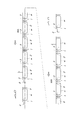
- FIG. 1A is a plan view of a transport traveling body
- FIG. 1B is a side view showing a traveling state of each transport traveling body in a work section.
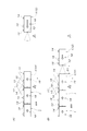
- FIG. 2 is a plan view for explaining a work section.
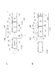
- FIG. 3A is a plan view showing a first stage of speed control of the conveying traveling body at the work section entrance side
- FIG. 3B is a plan view showing a second stage of the speed control.
- 4A is a plan view showing a third stage of the speed control
- FIG. 4B is a plan view showing a fourth stage of the speed control.
- FIG. 5A is a plan view showing a final stage of the speed control
- FIG. 5B is a plan view showing a first stage of speed control of the transport traveling body at the work section exit side.
- FIG. 6A is a plan view showing a second stage of the speed control
- FIG. 6B is a plan view showing a state where an abnormality has occurred in the second stage.
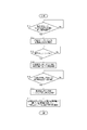
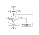
- FIG. 7 is a flowchart for explaining the control when the traveling body for transportation that travels at a high speed enters the work section.
- FIG. 8 is a flow chart for explaining the control for the transporting body at the end of the work section.
- FIG. 9 is a flowchart for explaining the control when the leading conveying traveling body is withdrawn from the work section.
- FIG. 10 is a flowchart for explaining the control for the second transport traveling body following the leading transport traveling body in the work section.
- the transport traveling body 1 used in this embodiment is composed of a combination of a self-propelled tow vehicle 2 and a transport carriage 3 towed by the tow vehicle 2.
- the tow truck 2 has a low floor structure that is low enough to allow the vehicle height to travel below the transport carriage 3, and the rear half of the tow truck 2 enters the lower side of the front end of the transport carriage 3.
- the vicinity of the center in the length direction and the vicinity of the center in the width direction near the front end of the transport carriage 3 are connected by the vertical connection shaft 4 so as to be relatively rotatable around the vertical connection shaft 4.
- the towing vehicle 2 includes a pair of left and right drive wheels 5 positioned on the left and right sides of the vertical connecting shaft 4, a pair of left and right motors 6 that rotate the drive wheels 5 in any direction, forward and reverse, respectively,
- a rear wheel 7 is provided at the center in the width direction near the end.
- the pair of left and right drive wheels 5 are fixed in a straight traveling direction, and the rear wheel 7 is a free wheel.
- the transport carriage 3 supports a transported object (such as an automobile body) W by a plurality of transported object support jigs 8 erected on the surface (work floor).
- a cover plate 9 covering the front side of the transport carriage 3 adjacent to the rear side in the work section extends rearward.
- the transport carriage 3 includes a pair of left and right front wheels 10 each having a free wheel provided at a position that does not interfere with the relative rotation of the towing vehicle 2 around the vertical connecting shaft 4 and a pair of left and right front wheels fixed in a straight direction.
- a rear wheel 11 is provided.
- the tow vehicle 2 is provided with an obstacle sensor 12 for detecting an obstacle that is within a predetermined forward distance range at the front end thereof.
- the front and rear end portions of the side face are oriented in the front-rear direction using the light emitter / receiver.
- the optical communication devices 13 and 14 are attached, and a wide optical communication device 15 in a lateral direction using a light projecting / receiving device is attached at an intermediate position on the side surface.
- a fixed position detection sensor 16 for detecting a marker disposed on the floor surface is attached to the bottom surface.
- the optical communication devices 13 and 14 oriented in the front-rear direction are oriented in the front-rear direction of the towing vehicle 2 of another transporting traveling body 1 having the same structure and located within a certain distance range in the front-rear direction of the transporting traveling body 1 on a straight path.
- Data communication is performed between the optical communication devices 13 and 14 using, for example, a 16-bit light beam, and the wide optical communication device 15 in the lateral direction is viewed as viewed from the wide optical communication device 15.
- data communication is performed using, for example, an 8-bit light beam with a wide optical communication device having the same structure on the ground side, which is located within a certain range before and after the traveling direction (for example, within a range of 60 degrees each before and after).
- Section WA is set.
- the front half of the towing vehicle 2 projecting forward from the front end of each transport carriage 3 enters the lower side of the rear end of the transport carriage 3 in the immediately preceding transport traveling body 1, and A cover plate 9 extending rearward from the rear side is covered on the front side of the transport carriage 3 in the transport body 1 just after.
- the travel control when the transport traveling body 1 enters the work section WA will be described with reference to FIGS.
- the transport traveling body 1 composed of the towing vehicle 2 and the transport carriage 3 is simplified and shown in a rectangular box shape in plan view.
- the fixed position detection sensor 16 on the bottom surface of the transport carriage 3 is displayed on the left side surface of the transport traveling body 1, and the optical communication devices 13, 14 and the wide optical communication device 15 are illustrated. 1 and the position shown in FIG. 2 are displayed on the right side surface of the traveling body 1 for conveyance opposite to the left and right.
- a measurement starting point P1 is set at a fixed position away from the work section WA by a certain distance upstream, and a docking confirmation position P2 is set near the entrance of the work section WA. Yes.
- markers that are detected by the fixed position detecting sensor 16 provided in the transporting traveling body 1 that passes through are provided on the floor surface or the like.
- a ground-side wide optical communication device 17 that performs data communication with the wide optical communication device 15 provided in the transport traveling body 1 that passes therethrough is provided.
- the ground-side wide optical communication device 17 also travels in the traveling direction of the transport traveling body 1 when the travel side of the transport traveling body 1 is viewed from the ground-side wide optical communication device 17.
- Data communication can be performed with the wide optical communication device 15 passing within a certain range before and after (for example, within each 60 degrees range).
- the ground-side wide optical communication devices 18a and 18b that perform data communication with the wide optical communication device 15 included in the transport traveling body 1 that passes therethrough.
- the ground wide optical communication devices 18 a and 18 b also have the transport traveling body 1 when the travel path side of the transport traveling body 1 is viewed from the various wide optical communication devices 18 a and 18 b.
- Data communication can be performed with the wide optical communication device 15 passing through a certain range in the traveling direction (for example, within a range of 60 degrees each in the longitudinal direction). In the figure, two identical grounds connected in parallel are connected.
- the wide wide optical communication devices 18a and 18b are used to expand the entire communication area in the traveling direction of the transport traveling body 1, but the number of wide optical communication devices to be used is not limited. If the communication area of one wide optical communication device is sufficiently wide, it can be configured by one wide optical communication device.
- a final process confirmation position P4 and a confirmation position P3 one prior to the final process are set in the vicinity of the exit of the work section WA with an interval about the same as the entire length of one transport traveling body 1. .
- markers detected by the fixed position detection sensor 16 provided in the transporting traveling body 1 that passes therethrough are provided on the floor surface or the like.
- the communication area of the two terrestrial wide optical communication devices 18a and 18b as a whole is at least between the wide optical communication devices 15 of the front and rear two transport traveling bodies 1 located at the two confirmation positions P3 and P4, respectively. It has enough space for data communication.
- the traveling speed set for each conveyance traveling body 1 that self-travels in the work section WA in a continuous state is determined by the operator on the work floor of each conveyance traveling body 1 (conveyance carriage 3).
- the work speed VL is a constant low speed at which work on the loaded object W can be performed while walking safely.
- the travel enable signal transmitted to the transport traveling body 1 located near the exit of the work section WA is transmitted through the front and rear optical communication devices 13 and 14 included in each transport travel body 1 in the work section WA.
- Each transport traveling body 1 is provided with a travel enable signal that is sequentially transmitted upstream to all the transport traveling bodies 1 and reaches the last transport traveling body 1 located near the entrance of the work section WA.
- a control device 19 is mounted on the towing vehicle 2 in each transport traveling body 1.
- the control device 19 controls the relay transmission of the travel enable signal and relays the travel enable signal.
- the control device 19 of the transport traveling body 1 relays the travel enable signal based on the relay travel enable signal.
- the pair of left and right motors 6 are controlled so that 1 runs straight at the work speed VL. Accordingly, all the transport traveling bodies 1 in the work section WA travel straight ahead while maintaining the work speed VL.
- the traveling-ready signal is transmitted to all the transporting traveling bodies 1 in the work section WA. Disappear.
- the control device 19 of each transport traveling body 1 stops the motor 6 based on the absence of the travel enable signal, so that all the transport traveling bodies 1 in the work section WA are stopped on the spot. It will be.
- the control device 19 of the specific transport traveling body 1 travels between the front and rear transport traveling bodies 1. Stops relaying of possible signals automatically.
- the relay transmission of the travel enable signal to be returned to the ground side control device is interrupted, and the ground side control device stops transmission of the travel enable signal based on this situation, so that all the traveling traveling bodies in the work section WA
- the traveling enable signal is not transmitted to 1 and all the transport traveling bodies 1 in the work section WA are stopped on the spot.
- the rearmost transport traveling body 1 located near the entrance of the work section WA is based on the determination that the rear transport traveling body 1 is the rearmost transport traveling body 1 from the rear transport traveling body 1. Stop control due to not receiving the downstream travel enable signal is not performed, and the travel enable signal received from the immediately preceding transport traveling body 1 is transmitted in the reverse direction in the reverse direction.
- FIG. 3A the rearmost transport traveling body 1 traveling at the work speed VL near the entrance of the work section WA is defined as a front transport traveling body 1Y, and immediately behind the front transport traveling body 1Y.
- the rear transport traveling body 1Z has its obstacle sensor 12 detecting an obstacle in the front detection area. If the obstacle sensor 12 detects an obstacle in the detection area ahead, if the obstacle sensor 12 detects an obstacle in the front detection area, the deceleration stop control program at the time of obstacle detection is set in advance. Accordingly, the control device 19 automatically executes deceleration stop control.
- the rear transfer traveling body 1Z passes a fixed position at a fixed upstream distance from the work section WA (FIG. 7-S1), for example, the measurement starting point P1 or a fixed position set separately from the measuring starting point P1 is passed.
- the deceleration stop control program at the time of obstacle detection by the obstacle sensor 12 is invalidated (FIG. 7-S2), and as shown in FIG. 3B, the rear-side transport traveling body 1Z changes the front-side transport traveling body 1Y.
- deceleration control for docking is started. That is, when the obstacle sensor 12 of the rear conveyance traveling body 1Z detects the front conveyance traveling body 1Y as an obstacle (FIG.
- deceleration stop at the time of obstacle detection performed during normal traveling is performed.
- the control program is not executed, and based on the detection signal ON of the obstacle sensor 12, deceleration control based on the inter-vehicle distance from the front conveyance traveling body 1Y is started (FIG. 7-S4).
- each of the front conveyance traveling body 1Y and the rear conveyance traveling body 1Z passes the measurement start point P1 (the ground side marker provided at the measurement start point P1 by the fixed position detection sensor 16).
- Current position information corresponding to the travel distances L1Y and L1Z from the detected time).
- the transmission pulse of the pulse encoder linked to the rotation of the drive wheel 5 is added and counted from the time when it passes the measurement starting point P1 by the calculation function provided in the control device 19, and the travel distance of the transport traveling body 1 is calculated. It is possible to have a count value that increases in proportion to the current position information.
- the control device 19 of the front transport traveling body 1Y transmits the calculated current position information to the rear transport traveling body 1Z via the optical communication devices 13 and 14, and the rear transport travel.
- the control device 19 of the body 1Z compares and calculates the received current position information of the front transporting traveling body 1Y and the current position information of the rear transporting traveling body 1Z calculated by itself to obtain a front transporting traveling body.
- the inter-vehicle distance d between 1Y is obtained.
- the motor 6 is controlled to decelerate the rear conveyance traveling body 1Z, and the calculated inter-vehicle distance d reaches a set value set in advance as the docking distance.
- the rear-side transport traveling body 1Z is controlled to be decelerated so that the rear-side transport traveling body 1Z is decelerated to the working speed VL (FIG. 7-S5).
- the rear conveyance traveling body 1Z approaches the front conveyance traveling body 1Y to the intended docking distance, and the same operation as the front conveyance traveling body 1Y is performed.
- a docking completion signal is transmitted to the front conveyance traveling body 1Y via the optical communication devices 13 and 14 (FIG. 7-S6), and the deceleration control based on the above-mentioned inter-vehicle distance is completed.
- the travel at the work speed VL is continued (FIG. 7-S7).
- the front transport traveling body 1Y has not reached the docking confirmation position P2, but when the front transport traveling body 1Y has reached the docking confirmation position P2 (FIG. 8-S1), when a docking completion signal has already been received from the rear-side transport traveling body 1Z (FIG. 8-S2), the wide-side optical communication device 15 through the ground-side wide-optical communication device 17 passes the ground side.
- the control device transmits a docking completion signal (FIG. 8-S3) and continues running at the working speed VL (FIG. 8-S4).
- the traveling body 1 for transportation travels at a work speed VL so as to maintain a continuous state (docking state).
- the stop control is executed on the spot and the relay action of the travel enable signal is stopped (FIG. 8-S5).
- the relay transmission of the travel enable signal to all the transport traveling bodies 1 in the work section WA is stopped, and the travel enable signal is also transmitted from the ground-side wide optical communication devices 18a and 18b on the exit side of the work section WA. Since it stops, all the traveling bodies 1 for conveyance in work area WA will stop and wait. This situation is notified to the ground side control device from the wide optical communication device 15 of the front conveyance traveling body 1Y that is waiting to be stopped via the ground wide optical communication device 17.
- the rear conveyance traveling body 1Z approaches the obstacle detection maximum inter-vehicle distance D1 with respect to the front conveyance traveling body 1Y that is waiting to stop, receives the deceleration control based on the above-mentioned inter-vehicle distance,
- the front transport traveling body 1Y which has been waiting to stop, is docked to the ground side control device via the wide optical communication device 15 and the ground wide optical communication device 17.
- Completion is notified, and the ground side control device sends a travel enable signal from the ground-side wide optical communication devices 18a, 18b on the exit side of the work section WA to the leading conveyance traveling body 1 that is stopped and waiting near the exit side of the work section WA.
- the transport traveling body 1 that has just exited from the work section WA and travels at a high speed VH is located at the last process confirmation position P4 of the previous exit transport traveling body 1A and the work section WA.
- the leading conveyance traveling body 1B is When the final process confirmation position P4 is reached (FIG.
- the information is transmitted from the wide optical communication device 15 of the leading transport traveling body 1B via the ground wide optical communication devices 18a and 18b to the ground control device. Is transmitted.
- the ground-side control device determines whether or not the immediately preceding leaving and traveling vehicle 1A is within a certain safety ensuring distance D2 from the leading and conveying vehicle 1B.
- the transmission of the travel enable signal from the ground-side wide optical communication devices 18a and 18b is continued.
- the control device 19 controls the acceleration of the motor 6 based on the fact that the final process confirmation position P4 has been reached and the receipt of the travel enable signal, and the head transport travel body 1B is moved from the work section WA at a high speed VH. Exit (FIG. 9-S3).
- the ground-side control device determines that the traveling body 1A for immediately leaving and exiting is within the certain safety ensuring distance D2, as shown by a virtual line in FIG. 5B, travel from the ground-side wide optical communication devices 18a and 18b. Since transmission of the enabling signal is stopped, the relay transmission of the enabling signal described above is stopped, and all the transporting traveling bodies 1 in the work section WA including the leading transporting traveling body 1B are stopped and waited on the spot. (FIG. 9-S4). When the immediately-retreating traveling body 1A moves forward from within the certain safety ensuring distance D2, the control described above is performed, and at the same time the leading transportation body 1B leaves the work section WA at the high speed VH.
- the second transport traveling body 1C and all the transport traveling bodies 1 in the subsequent work section WA resume traveling at the work speed VL.
- the leading conveyance traveling body 1B that exits from the work section WA at a high speed VH has the obstacle sensor 12 that has been disabled before entering the work section WA before reaching the final process confirmation position P4, as will be described later. Since the deceleration stop control program based on the obstacle detection is effectively returned, the deceleration stop control based on the obstacle detection of the normal obstacle sensor 12 is used together.
- the leading communication traveling body 1B passing through the final process confirmation position P4 changes from the optical communication device 13, 14 (FIG. 10-S2), the second transport traveling body 1C continues to travel at the working speed VL (FIG. 10-S3).
- the transport traveling body 1B travels away from the work section WA at a high speed VH from the final process confirmation position P4, and the inter-vehicle distance between the leading transport traveling body 1B and the second transport traveling body 1C is the optical communication device.
- the second transport traveling body 1C cannot inherit the travel enable signal from the front transport traveling body 1B via the front and rear optical communication devices 13 and 14.
- the second transport traveling body 1C between the confirmation position P3 immediately before the final process and the final process confirmation position P4 travels from the ground-side wide optical communication devices 18a and 18b via the wide optical communication device 15.
- the enable signal has been received (FIG. 10-S4)
- it is possible to continue traveling at the work speed VL until the final process confirmation position P4 is reached (FIG. 10-S7) (FIG. 10). -S6).
- the second transport traveling body 1C receives the travel enable signal from the ground-side wide optical communication devices 18a and 18b, the second transport traveling body 1C is located within the work section WA that is continuously rearward from the second transport traveling body 1C. Relay transmission of the travel enable signal to all the transport traveling bodies 1 is also continued, and all the transport traveling bodies 1 in the work section WA follow the second transport traveling body 1C and travel at the work speed VL.
- the deceleration stop control program based on the obstacle detection of the obstacle sensor 12 of each transport traveling body 1 that was invalidated before entering the work section WA passed the confirmation position P3 one step before the final process.
- the deceleration stop control based on the obstacle detection of the obstacle sensor 12 is used together. Accordingly, as shown in FIG. 6, the obstacle sensor of the second transport traveling body 1C before reaching the final process confirmation position P4 for some reason due to the leading transport traveling body 1B started at high speed from the final process confirmation position P4. 2C, the second transport traveling body 1C stops on the spot by the action of the normal deceleration stop control program based on the obstacle detection of the obstacle sensor 12, and subsequently continues. Since the relay transmission of the travel enable signal to the transport traveling body 1 is also stopped, all the transport traveling bodies 1 in the work section WA starting from the second transport traveling body 1C have stopped abnormally. The transportation traveling body 1B stops and waits on the spot until the traveling at the high speed VH is resumed.
- the second transporting travel body that has passed the confirmation position P3 one step before the final process. 1C stops on the spot, and relay transmission of the travel enable signal to the subsequent transport traveling body 1 is also cut off, so that all transport objects in the work section WA starting from the second transport traveling body 1C are used.
- the traveling body 1 stops and waits on the spot until the transmission of the travel enable signal from the ground side wide optical communication devices 18a and 18b is resumed (FIG. 10-S8).
- the transport traveling body 1 traveling at a high speed is automatically decelerated and entered into the work section WA, and in this work section WA, all the transport traveling bodies 1 are continuously adjacent to each other.
- Each transport traveling body 1 that has traveled at a constant work speed VL in the state and has reached the exit of the work section WA can be automatically accelerated and retreated at a high speed VH.
- the traveling control method for a transport traveling body according to the present invention travels while maintaining a continuous state at a constant work speed for a self-propelled transport traveling body on which an automobile body is loaded in a certain work section in an automobile assembly line. It can be used as a driving control method when
Landscapes
- Engineering & Computer Science (AREA)
- Manufacturing & Machinery (AREA)
- Chemical & Material Sciences (AREA)
- Combustion & Propulsion (AREA)
- Transportation (AREA)
- Mechanical Engineering (AREA)
- Aviation & Aerospace Engineering (AREA)
- Radar, Positioning & Navigation (AREA)
- Remote Sensing (AREA)
- Physics & Mathematics (AREA)
- General Physics & Mathematics (AREA)
- Automation & Control Theory (AREA)
- Control Of Position, Course, Altitude, Or Attitude Of Moving Bodies (AREA)
- Control Of Conveyors (AREA)
- Automatic Assembly (AREA)
- Platform Screen Doors And Railroad Systems (AREA)
- Warehouses Or Storage Devices (AREA)
Abstract
Description
2 牽引車
3 搬送台車
4 垂直連結軸
5 駆動車輪
6 モーター
7 後輪
12 障害物センサー
13,14 光通信装置
15 巾広光通信装置
16 定位置検出用センサー
17,18a,18b 地上側巾広光通信装置
19 制御装置
P1 計測起点
P2 ドッキング確認位置
P3 最終工程1つ手前の確認位置
P4 最終工程確認位置
L1Y,L1Z 搬送用走行体1Y及び1Zの走行距離
d,D3 車間距離
D1 障害物検出最大車間距離
D2 一定安全確保距離
WA 作業区間
Claims (6)
- 自走式搬送用走行体の走行経路中に、各搬送用走行体が走行方向に連続する状態を保って一定低速度の作業速度で自走する作業区間が設定された搬送設備において、各搬送用走行体には、作業区間内において前後に隣り合う搬送用走行体間でデータ通信を行うデータ通信手段と、地上側通信装置との間でデータ通信を行う機上側通信装置が設けられ、前記作業区間の一端部には、通過する搬送用走行体の前記機上側通信装置に走行可信号を送信する地上側通信装置が配設され、この地上側通信装置から受信した走行可信号を、作業区間内を走行する他の全ての搬送用走行体に、各搬送用走行体が備える前記データ通信手段を介して伝送し、作業区間内の各搬送用走行体を、受信した走行可信号に基づいて作業速度で自走させることを特徴とする、搬送用走行体の走行制御方法。
- 前記地上側通信装置から送信された走行可信号は、各搬送用走行体の前記データ通信手段を介して作業区間の他端部を走行する搬送用走行体に達した後、各搬送用走行体の前記データ通信手段を介して作業区間内の各搬送用走行体を逆方向に伝送し、当該走行可信号を、作業区間の一端部を走行する搬送用走行体から前記機上側通信装置を経由して前記地上側通信装置に戻すことを特徴とする、請求項1に記載の搬送用走行体の走行制御方法。
- 作業区間内で走行不可となった搬送用走行体では、隣り合う搬送用走行体への走行可信号の伝送を中止させ、作業区間の一端部を走行する搬送用走行体から前記地上側通信装置への走行可信号の戻りが無いことに基づいて当該地上側通信装置からの走行可信号の送信を断ち、作業区間内の全ての搬送用走行体をその場で停止させることを特徴とする、請求項2に記載の搬送用走行体の走行制御方法。
- 前記データ通信手段が投受光器を使用した光通信手段である、請求項1に記載の搬送用走行体の走行制御方法。
- 前記地上側通信装置と機上側通信装置とが、搬送用走行体の走行方向に長い一定範囲の通信エリアを有する投受光器を使用した光通信手段である、請求項1に記載の搬送用走行体の走行制御方法。
- 前記地上側通信装置は、複数の前記光通信手段によって構成され、各光通信手段が、夫々の通信エリアが一部重なるように搬送用走行体の走行方向に適当間隔おきに並設されている、請求項5に記載の搬送用走行体の走行制御方法。
Priority Applications (3)
| Application Number | Priority Date | Filing Date | Title |
|---|---|---|---|
| CN201280004089.8A CN103261989B (zh) | 2011-02-02 | 2012-01-27 | 搬送用行走体的行走控制方法 |
| BR112013010510-0A BR112013010510B1 (pt) | 2011-02-02 | 2012-01-27 | método para controlar o movimento de transportadores |
| US13/923,051 US8862306B2 (en) | 2011-02-02 | 2013-06-20 | Method for controlling movement of travelling carriers |
Applications Claiming Priority (2)
| Application Number | Priority Date | Filing Date | Title |
|---|---|---|---|
| JP2011-020547 | 2011-02-02 | ||
| JP2011020547A JP5448102B2 (ja) | 2011-02-02 | 2011-02-02 | 搬送用走行体の走行制御方法 |
Related Child Applications (1)
| Application Number | Title | Priority Date | Filing Date |
|---|---|---|---|
| US13/923,051 Continuation US8862306B2 (en) | 2011-02-02 | 2013-06-20 | Method for controlling movement of travelling carriers |
Publications (1)
| Publication Number | Publication Date |
|---|---|
| WO2012105451A1 true WO2012105451A1 (ja) | 2012-08-09 |
Family
ID=46602667
Family Applications (1)
| Application Number | Title | Priority Date | Filing Date |
|---|---|---|---|
| PCT/JP2012/051836 Ceased WO2012105451A1 (ja) | 2011-02-02 | 2012-01-27 | 搬送用走行体の走行制御方法 |
Country Status (5)
| Country | Link |
|---|---|
| US (1) | US8862306B2 (ja) |
| JP (1) | JP5448102B2 (ja) |
| CN (1) | CN103261989B (ja) |
| BR (1) | BR112013010510B1 (ja) |
| WO (1) | WO2012105451A1 (ja) |
Cited By (1)
| Publication number | Priority date | Publication date | Assignee | Title |
|---|---|---|---|---|
| US9672743B2 (en) | 2013-09-11 | 2017-06-06 | Hitachi Construction Machinery Co., Ltd. | Vehicle traffic control system |
Families Citing this family (7)
| Publication number | Priority date | Publication date | Assignee | Title |
|---|---|---|---|---|
| JP2014190114A (ja) * | 2013-03-28 | 2014-10-06 | Daifuku Co Ltd | 搬送用走行体の走行経路構造 |
| CN110636981B (zh) | 2017-03-08 | 2021-10-26 | 雷勃美国公司 | 包裹分拣传送模块和系统及其方法 |
| US10532894B2 (en) | 2017-03-10 | 2020-01-14 | Regal Beloit America, Inc. | Modular transfer units, systems, and methods |
| JP6963908B2 (ja) * | 2017-05-09 | 2021-11-10 | 株式会社ダイフク | 物品搬送車 |
| AU2018372168B2 (en) | 2017-11-22 | 2024-07-18 | Regal Beloit America, Inc. | Modular sortation units, systems, and methods |
| JP7438660B2 (ja) * | 2017-11-30 | 2024-02-27 | キヤノン株式会社 | 搬送システム、搬送方法、および物品の製造方法 |
| NO346304B1 (en) * | 2020-06-25 | 2022-05-30 | Autostore Tech As | System and method of operating an automated storage and retrieval system |
Citations (3)
| Publication number | Priority date | Publication date | Assignee | Title |
|---|---|---|---|---|
| JPH044409A (ja) * | 1990-04-20 | 1992-01-08 | Tsubakimoto Chain Co | 車間距離保持装置及び車間距離保持方法 |
| JPH06211332A (ja) * | 1993-01-19 | 1994-08-02 | Nakanishi Kinzoku Kogyo Kk | 搬送装置の切離しゾーンにおける台車走行速度制御 方法 |
| JP2001216024A (ja) * | 2000-02-01 | 2001-08-10 | Daifuku Co Ltd | 荷搬送設備 |
Family Cites Families (4)
| Publication number | Priority date | Publication date | Assignee | Title |
|---|---|---|---|---|
| US6129025A (en) * | 1995-07-04 | 2000-10-10 | Minakami; Hiroyuki | Traffic/transportation system |
| JP4463757B2 (ja) * | 2005-12-09 | 2010-05-19 | 株式会社小松製作所 | 車両の走行制御装置 |
| US8428770B2 (en) * | 2009-02-06 | 2013-04-23 | Autran Corp | Automated transport control system |
| JP5448101B2 (ja) * | 2011-02-02 | 2014-03-19 | 株式会社ダイフク | 搬送用走行体の走行制御方法 |
-
2011
- 2011-02-02 JP JP2011020547A patent/JP5448102B2/ja active Active
-
2012
- 2012-01-27 CN CN201280004089.8A patent/CN103261989B/zh active Active
- 2012-01-27 WO PCT/JP2012/051836 patent/WO2012105451A1/ja not_active Ceased
- 2012-01-27 BR BR112013010510-0A patent/BR112013010510B1/pt active IP Right Grant
-
2013
- 2013-06-20 US US13/923,051 patent/US8862306B2/en active Active
Patent Citations (3)
| Publication number | Priority date | Publication date | Assignee | Title |
|---|---|---|---|---|
| JPH044409A (ja) * | 1990-04-20 | 1992-01-08 | Tsubakimoto Chain Co | 車間距離保持装置及び車間距離保持方法 |
| JPH06211332A (ja) * | 1993-01-19 | 1994-08-02 | Nakanishi Kinzoku Kogyo Kk | 搬送装置の切離しゾーンにおける台車走行速度制御 方法 |
| JP2001216024A (ja) * | 2000-02-01 | 2001-08-10 | Daifuku Co Ltd | 荷搬送設備 |
Cited By (1)
| Publication number | Priority date | Publication date | Assignee | Title |
|---|---|---|---|---|
| US9672743B2 (en) | 2013-09-11 | 2017-06-06 | Hitachi Construction Machinery Co., Ltd. | Vehicle traffic control system |
Also Published As
| Publication number | Publication date |
|---|---|
| BR112013010510A2 (pt) | 2016-08-02 |
| US8862306B2 (en) | 2014-10-14 |
| CN103261989A (zh) | 2013-08-21 |
| JP2012160106A (ja) | 2012-08-23 |
| US20130282223A1 (en) | 2013-10-24 |
| JP5448102B2 (ja) | 2014-03-19 |
| BR112013010510B1 (pt) | 2021-03-02 |
| CN103261989B (zh) | 2015-06-10 |
Similar Documents
| Publication | Publication Date | Title |
|---|---|---|
| JP5448101B2 (ja) | 搬送用走行体の走行制御方法 | |
| JP5448102B2 (ja) | 搬送用走行体の走行制御方法 | |
| TWI557525B (zh) | A Moving Control Method for Moving Vehicles in a Moving System and a Turning Section | |
| KR20180092875A (ko) | 물품 반송 설비 | |
| CN109153396B (zh) | 车载装置和地面系统 | |
| KR20190058376A (ko) | 자율 주행 차량 견인 시스템 및 방법 | |
| KR102142202B1 (ko) | 자동차의 적어도 반자율적 조종으로 주차 공간으로부터 최종 위치까지 자동차를 출차하는 방법, 운전자 보조 시스템 및 자동차 | |
| CN104828450A (zh) | 智能搬运车及智能搬运车用交叉口防撞系统 | |
| KR20170094502A (ko) | 물품 반송 설비 | |
| JP2019046013A (ja) | 自動運転車両の走行管制方法及び走行管制装置 | |
| KR20190027738A (ko) | 반송 시스템 | |
| KR20160138155A (ko) | 열차 제어 방법 및 열차 제어 시스템 | |
| US10000218B2 (en) | Bi-modal traffic system | |
| JP2018043599A (ja) | 鉱山用作業機械及びその後方監視方法 | |
| CA2923808A1 (en) | Work vehicle control system | |
| JP5390419B2 (ja) | 自動搬送車 | |
| KR20190027374A (ko) | 항공기 육상 활주에 대한 개선 | |
| CN116811843A (zh) | 泊车控制方法、装置、设备及计算机存储介质 | |
| JP2017107270A (ja) | 走行管理システム | |
| CN116457738B (zh) | 用于协调无人驾驶运输车辆的方法和系统 | |
| CN204642872U (zh) | 智能搬运车及智能搬运车用交叉口防撞系统 | |
| KR101989797B1 (ko) | 교차로에서의 무인대차 주행 제어 시스템 및 방법 | |
| CN115135571A (zh) | 根据前导车辆对作为跟随车辆的商用车辆的受控倒车进行横向和纵向引导的技术 | |
| JP3607966B2 (ja) | 走行支援システム | |
| JP6005411B2 (ja) | 列車位置検出システム |
Legal Events
| Date | Code | Title | Description |
|---|---|---|---|
| 121 | Ep: the epo has been informed by wipo that ep was designated in this application |
Ref document number: 12742489 Country of ref document: EP Kind code of ref document: A1 |
|
| NENP | Non-entry into the national phase |
Ref country code: DE |
|
| REG | Reference to national code |
Ref country code: BR Ref legal event code: B01A Ref document number: 112013010510 Country of ref document: BR |
|
| 122 | Ep: pct application non-entry in european phase |
Ref document number: 12742489 Country of ref document: EP Kind code of ref document: A1 |
|
| ENP | Entry into the national phase |
Ref document number: 112013010510 Country of ref document: BR Kind code of ref document: A2 Effective date: 20130429 |