WO2012105291A1 - 受信装置、受信方法、通信システムおよび通信方法 - Google Patents
受信装置、受信方法、通信システムおよび通信方法 Download PDFInfo
- Publication number
- WO2012105291A1 WO2012105291A1 PCT/JP2012/050548 JP2012050548W WO2012105291A1 WO 2012105291 A1 WO2012105291 A1 WO 2012105291A1 JP 2012050548 W JP2012050548 W JP 2012050548W WO 2012105291 A1 WO2012105291 A1 WO 2012105291A1
- Authority
- WO
- WIPO (PCT)
- Prior art keywords
- channel impulse
- impulse response
- unit
- path
- estimation
- Prior art date
- Legal status (The legal status is an assumption and is not a legal conclusion. Google has not performed a legal analysis and makes no representation as to the accuracy of the status listed.)
- Ceased
Links
Images


Classifications
-
- H—ELECTRICITY
- H04—ELECTRIC COMMUNICATION TECHNIQUE
- H04L—TRANSMISSION OF DIGITAL INFORMATION, e.g. TELEGRAPHIC COMMUNICATION
- H04L25/00—Baseband systems
- H04L25/02—Details ; arrangements for supplying electrical power along data transmission lines
- H04L25/0202—Channel estimation
- H04L25/0212—Channel estimation of impulse response
-
- H—ELECTRICITY
- H04—ELECTRIC COMMUNICATION TECHNIQUE
- H04L—TRANSMISSION OF DIGITAL INFORMATION, e.g. TELEGRAPHIC COMMUNICATION
- H04L25/00—Baseband systems
- H04L25/02—Details ; arrangements for supplying electrical power along data transmission lines
- H04L25/0202—Channel estimation
- H04L25/022—Channel estimation of frequency response
-
- H—ELECTRICITY
- H04—ELECTRIC COMMUNICATION TECHNIQUE
- H04L—TRANSMISSION OF DIGITAL INFORMATION, e.g. TELEGRAPHIC COMMUNICATION
- H04L27/00—Modulated-carrier systems
- H04L27/26—Systems using multi-frequency codes
- H04L27/2601—Multicarrier modulation systems
- H04L27/2647—Arrangements specific to the receiver only
- H04L27/2649—Demodulators
Definitions
- the present invention relates to a receiving device, a receiving method, a communication system, and a communication method.
- propagation path estimation is performed by the receiving device in order to grasp the wireless propagation status. Since the receiving apparatus performs demodulation / decoding using the propagation path estimation result, the transmission characteristics are greatly degraded when the propagation path estimation accuracy is lowered. In order to perform highly accurate propagation path estimation, it is necessary to know the statistical properties of the propagation path.
- the statistical properties of the propagation path include the power of the path constituting the propagation path and the delay time with the path received in advance.
- FIG. 1 is an example of a channel impulse response that is a propagation path in the time domain, and arrows numbered 100-1 to 100-8 represent paths. Note that 100-4 and 100-5 mean delay times in which there is no substantial path, but here it is assumed that there is also a path with zero power at such a position.
- Non-Patent Document 1 describes a method for estimating all paths from a preceding path to a path with a delay time determined as propagation path estimation in scattered pilot OFDM. Taking FIG. 1 as an example, for example, paths 100-1 to 100-8 are estimated.
- the propagation path estimation value includes noise and interference correspondingly, and the estimation accuracy decreases.
- the present invention has been made in view of such circumstances, and an object of the present invention is to provide a receiving apparatus capable of highly accurate propagation path estimation.
- the receiving apparatus of the present invention includes a propagation path estimation unit that performs propagation path estimation, wherein the propagation path estimation unit calculates a temporary channel impulse response estimation value, and the temporary channel impulse response estimation value.
- a path extraction unit that extracts a path used for calculating a channel impulse response estimation value, and a channel impulse response estimation unit that calculates a channel impulse response estimation value using the path extracted by the path extraction unit;
- a frequency response estimator for performing time-frequency conversion on the channel impulse response estimated value and converting it to a frequency response estimated value.
- the path extraction unit may extract a predetermined number of paths in descending order of power of the temporary channel impulse response estimation value.
- the propagation path estimation unit may further include a selection unit that selects the best one from two or more channel impulse estimation values.
- the propagation path estimation unit may include a plurality of the path extraction unit and the channel impulse response estimation unit.
- the propagation path estimation unit may sequentially repeat the calculation of the channel impulse response estimation value.
- the path extraction unit may sequentially calculate the channel impulse response estimated value while reducing the number of extracted paths.
- the path extraction unit may sequentially calculate the channel impulse response estimation value while increasing the number of extraction paths.
- the propagation path estimation unit may end the estimation process when the channel impulse response estimation value is calculated a predetermined number of times.
- the selection unit may select the best estimated value using a Bayes information criterion.
- the accuracy of propagation path estimation can be greatly improved.
- FIG. 1 is a schematic block diagram of a transmission device according to a first embodiment of the present invention. It is a figure which shows the example to which the mapping part a104 maps a pilot symbol and a modulation signal. It is a schematic block diagram which shows the structure of the receiver b1 which concerns on the 1st Embodiment of this invention. It is a schematic block diagram which shows the structure of the propagation path estimation part b106. It is the schematic which shows an example of the received signal which concerns on the 1st Embodiment of this invention. It is a figure which shows an example of a delay profile.
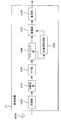
- FIG. 2 is a schematic block diagram of the transmission apparatus according to the first embodiment of the present invention.
- the transmission device is a transmission device a1.
- a transmission device a1 is also called a pilot generation unit a101, a coding unit a102, a modulation unit a103, a mapping unit a104, an IFFT (Inverse Fast Fourier Transform) unit (inverse fast Fourier transform) unit (frequency time conversion unit). ) A105, a GI (Guard Interval) insertion unit a106, a transmission unit a107, and a transmission antenna a108, and transmits an OFDM signal.
- Pilot generating section a101 generates a pilot symbol in which the receiving apparatus stores in advance the amplitude value of the waveform (or signal sequence thereof) and outputs the pilot symbol to mapping section a104.
- the receiving device is referred to as a receiving device b1.
- the receiving apparatus b1 performs propagation path estimation using the pilot symbol as a reference signal.
- the encoding unit a102 encodes and encodes information bits to be transmitted to the receiving apparatus b1 using an error correction code such as a convolutional code, a turbo code, and an LDPC (Low Density Parity Check) code. Generate bits.
- the encoding unit a102 outputs the generated encoded bits to the modulating unit a103.
- the modulation unit a103 modulates the coded bits input from the coding unit a102 using a modulation method such as PSK (Phase Shift Keying) or QAM (Quadrature Amplitude Modulation), and converts the modulation symbol. Generate. Modulation section a103 outputs the generated modulation symbol to mapping section a104.
- a modulation method such as PSK (Phase Shift Keying) or QAM (Quadrature Amplitude Modulation
- the mapping unit a104 maps the pilot symbol input from the pilot generation unit a101 and the modulation symbol input from the modulation unit a103 to a resource (time-frequency band) based on predetermined mapping information.
- a domain signal is generated, and the generated frequency domain signal is output to IFFT section a105.
- a resource is a unit in which a modulation symbol is arranged, which is composed of one subcarrier and one FFT section described later in a frame transmitted by the transmission apparatus a1.
- the mapping information is determined by the transmission device a1, and is notified in advance from the transmission device a1 to the reception device b1.
- FIG. 3 is an example in which the mapping unit a104 maps pilot symbols and modulated signals.
- a scattered pilot which is a discrete pilot arrangement, will be described as an example.
- the present invention is not limited to this and can be applied to other arrangements such as a preamble.
- the IFFT unit a105 performs frequency-time conversion on the frequency domain signal input from the mapping unit a104 to generate a time domain signal.
- a time interval of a unit for performing IFFT is referred to as an FFT interval.
- the IFFT unit a105 outputs the generated time domain signal to the GI insertion unit a106.
- the GI insertion unit a106 adds a GI for each signal in the FFT section to the time domain signal input from the IFFT unit a105.
- GI is a known signal using a cyclic prefix (Cyclic Prefix: CP), which is a part of the rear of the signal in the FFT section, zero padding in which the zero section continues, Golay code, or the like.
- CP Cyclic Prefix
- the GI insertion unit a106 adds such a signal to the front of the signal in the FFT interval.
- the FFT interval and the GI time interval (referred to as GI interval) added to the signal in the time interval by the GI insertion unit a106 are collectively referred to as an OFDM symbol interval.
- a signal in the OFDM symbol section is called an OFDM symbol.
- the GI insertion unit a106 outputs the signal with the GI added to the transmission unit a107.
- the GI may be inserted behind the FFT interval.
- a part of the replica in front of the FFT interval is added behind the signal in the FFT interval.
- the periodicity may be maintained in the OFDM symbol period, and is not limited to the above.
- the transmission unit a107 performs digital / analog conversion on the signal input from the GI insertion unit a106, and shapes the converted analog signal.
- the transmission unit a107 upconverts the waveform-shaped signal from the baseband to the radio frequency band, and transmits the signal from the transmission antenna a108 to the reception device b1.
- FIG. 4 is a schematic block diagram showing the configuration of the receiving device b1 according to this embodiment.
- a receiving device b1 includes a receiving antenna b101, a receiving unit b102, a GI removing unit b103, an FFT unit (also referred to as a time frequency converting unit) b104, a demapping unit b105, and a propagation path estimating unit b106.
- the reception unit b102 receives the transmission signal transmitted by the transmission device a1 via the reception antenna b101.
- the receiving unit b102 performs frequency conversion and analog / digital conversion on the received signal.
- the GI removal unit b103 removes the GI from the reception signal input from the reception unit b102 and outputs the GI to the FFT unit b104.
- the FFT unit b104 performs time frequency conversion on the time domain signal input from the GI removal unit b103, and outputs the converted frequency domain signal to the demapping unit b105.
- the demapping unit b105 performs demapping based on the mapping information notified in advance from the transmission device a1, and outputs the received signal of the subcarrier to which the separated pilot symbol is transmitted to the propagation path estimation unit b106. Also, the received signal of the subcarrier transmitted with data is output to demodulation section b107.
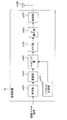
- FIG. 5 is a schematic block diagram showing the configuration of the propagation path estimation unit b106.
- a propagation path estimation unit b106 includes a temporary channel impulse response estimation unit b106-1, a path extraction unit 106-3, a channel impulse response estimation unit b106-4, a frequency response estimation unit b1-6-5, It is comprised including.
- Temporary channel impulse response estimation unit b106-1 estimates a frequency response based on the received signal input from demapping unit b105 and a pilot symbol stored in advance, and performs IFFT on the frequency response to estimate the temporary channel impulse response estimation value. Is calculated and output to the path extraction unit b106-3.
- Path extraction unit b106-3 among the tentative channel impulse response estimation value output from the temporary channel impulse response estimation unit B106-1, N to S path extraction in descending order of power. As a result, the path not selected is set to 0. The result is output to channel impulse response estimation section b106-4.
- the channel impulse response estimation unit b106-4 estimates the channel impulse response using the path extraction information output from the path extraction unit b106-3 and the temporary channel impulse response estimation value. This operation will be described in detail later.
- the channel impulse response estimation value is output to the frequency response estimation unit b106-5.
- the frequency response estimation unit b106-5 performs time-frequency conversion on the channel impulse response estimation value output from the channel impulse response estimation unit b106-4, and outputs the result to the demodulation unit b107.
- the propagation path estimation unit b106 uses a pilot symbol stored in advance, and measures noise power in a subcarrier (referred to as pilot subcarrier) in which the pilot symbol is arranged. A specific calculation method will be described later together with the operation principle.
- the demodulation unit b107 calculates filter coefficients such as ZF (Zero Forcing) standard and MMSE (Minimum Mean Square Error) standard using the frequency response and noise power input from the propagation path estimation unit b106.
- the demodulator b107 compensates for signal amplitude and phase fluctuations (referred to as propagation path compensation) using the calculated filter coefficients.
- the demodulator b107 outputs a bit log likelihood ratio (LLR) as a result of the demodulation process to the decoder b108.
- LLR bit log likelihood ratio
- the decoding unit b108 for example, performs maximum likelihood decoding (MLD; Maximum Likelihood Decoding), maximum a posteriori probability (MAP), log-MAP, Max- Decoding processing is performed using log-MAP, SOVA (Soft Output Viterbi Algorithm), or the like.
- MLD Maximum Likelihood Decoding
- MAP maximum a posteriori probability
- log-MAP maximum a posteriori probability
- Max- Decoding processing is performed using log-MAP, SOVA (Soft Output Viterbi Algorithm), or the like.
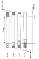
- FIG. 6 is a schematic diagram illustrating an example of a received signal according to the present embodiment.
- the maximum delay does not exceed the GI length and there is no interference due to the previous OFDM symbol.
- the horizontal axis is a time axis, which is a discrete time divided by a predetermined time width.
- a hatched area with diagonal lines rising diagonally to the right indicates GI.
- a hatched area with diagonal lines on the upper left represents received signals of the preceding and succeeding OFDM symbols.
- N is the number of points in the FFT (Fast Fourier Transform) section (also the number of points in the IFFT (Inverse Fast Fourier Transform) section), and N g is the number of GI points.
- the number of points is the number of discrete times.
- the reception signal r i, k of the i-th symbol at the k-th discrete time received by the reception unit b102 is expressed by the following equations (1) and (2).
- D is the maximum delay time
- h i d is the complex amplitude in the path of the channel number d of the i-th symbol (referred to as the d-th path)
- s i, k are the time domain of the i-th symbol k-th discrete time. This is a transmission signal
- z i, k is noise in the time domain of the i-th symbol.
- N is the number of points in the FFT interval
- S i, n is the modulation signal of the i-th symbol of the n-th subcarrier
- N g is the number of points in the GI interval (see FIG. 6)
- j is an imaginary unit.
- a signal R i, n after time-frequency conversion is performed on the received signal r i, k in the FFT section by the FFT unit b104 is expressed by the following equation (3).
- Z i, n is noise in the n-th subcarrier.
- H i, n is the frequency response of the i-th symbol and the n-th subcarrier, and is expressed by the following equation (4).
- the demodulator b107 calculates the demodulated symbol S ′ i, n using the following equation (5).
- Equation (5) ⁇ z 2 is the power of Z i, n and is expressed as in the following Equation (6).
- E [X] represents an ensemble average of X. This power can be calculated as in the following equation (7), and the result is used to calculate the demodulated symbol S ′ i, n using equation (5).
- Equation (7) is an estimated value of ⁇ z 2
- P i is a set representing pilot subcarriers in the i-th symbol. Note that this is a calculation method using the fact that Equation (7) can be expressed by the following Equation (8) when it is assumed that a sufficient number of arithmetic averages are equal to the ensemble average.
- This equation is for the case where the power of the pilot signal is normalized to 1 and the power average of the frequency response is normalized to 1. That is, this expression is a case where the following expression (9) is satisfied.
- the pilot signal power is not 1, an adjustment factor for that amount may be introduced. Further, the normalization of the frequency response is caused by amplitude adjustment when analog-to-digital conversion is performed in the receiving unit b102.
- the demodulator b107 calculates a bit log likelihood ratio from the demodulated symbol S ′ i, n in Expression (5).
- An equivalent amplitude gain is used for this calculation process.
- the bit log likelihood ratio ⁇ is expressed by the following equations (11) and (12) with respect to the equivalent amplitude gain ⁇ i, n of the n-th subcarrier expressed by the following equation (10). ).
- the equations (11) and (12) are respectively expressed as the bit log likelihood ratios ⁇ (b i, n, 0 ) of the first bit b i, n, 0 and the second bit b i, n, 1 . 0 ), ⁇ (b i, n, 1 ).
- Temporary channel impulse response estimation section b 106-1 first calculates an estimated value H ′ i, n of the frequency response based on equation (3). Specifically, it estimates like following Formula (13).
- the signal S i, n of the nth subcarrier needs to be known, but a pilot symbol or the like may be used.
- n 1 , n 2 ,..., n P pilot subcarriers, frequency response estimation vector
- n 1 is the lowest subcarrier
- n 2 is the next subcarrier
- n 3 is the next subcarrier
- NP is the number of pilot subcarriers
- L is an assumed maximum delay time, which may be fixed when the receiving device b1 is developed, or variable at the design stage, and updated when updating the firmware, software, etc. of the receiving device b1. May be equal.
- Each element of represents a correlation between paths.
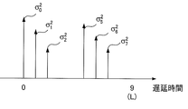
- This is a diagonal matrix of size L + 1 with the value of the average power of the path from 0 to L in the main diagonal element, and represents the delay profile.
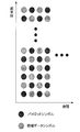
- FIG. 7 is an example of a delay profile, and there is no path at the positions of path numbers 3, 4, 8, and 9.
- the temporary channel impulse response estimation unit b106-1 performs IFFT on Hi , P shown in Expression (14) as shown in the following Expression (19).
- reference numerals 801 to 810 denote paths. Compared to FIG. 7, due to the influence of noise and interference, the number and arrangement of pilot signals, etc., it is observed that there are paths such as 804, 805, 809, and 810 even at positions where there are no paths in FIG. 7.
- the path extractor B106-3 among these paths, N S path selecting a high power order.
- the value of N S may be previously decided when designing the receiving apparatus b1, in the design phase leave the variable, the reception device b1 firmware, may be equal to update when updating software, etc. .
- the frequency response estimation unit b106-5 performs time-frequency conversion on the channel impulse response estimated value obtained by Expression (20), and converts it to a frequency response estimated value for demodulation.
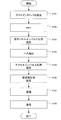
- FIG. 9 is a flowchart showing the operation of the receiving apparatus according to this embodiment. The operation shown in this figure is processing after the receiving unit b102 in FIG. 4 outputs the received signal to the GI removing unit b103.
- Step S101 The GI removing unit b103 removes the GI from the received signal. Then, it progresses to step S102.
- Step S102 The FFT unit b104 performs time-frequency conversion on the signal obtained in Step S101.
- the demapping unit b105 separates data and pilot from the obtained frequency domain signal. After outputting the received signal of the pilot subcarrier to the propagation path estimation unit b106, the process proceeds to step S103.
- Step S103 The temporary channel impulse response estimation unit b106-1 in the propagation path estimation unit b106 calculates a temporary channel impulse response estimation value using the received signal of the pilot subcarrier obtained in step S102. After the estimated value is output to the path extraction unit b106-3, the process proceeds to step S104.
- Step S104 The path extraction unit b106-3 performs path extraction using the temporary channel impulse response estimation value obtained in step S103, and outputs the result to the channel impulse response estimation unit b106-4. Thereafter, the process proceeds to step S105.
- Step S105 The channel impulse response estimation unit b106-4 calculates a channel impulse response estimation value using the path information obtained in step S104. Thereafter, the process proceeds to step S106.
- Step S106 The frequency response estimation unit b106-5 performs time-frequency conversion on the channel impulse response estimated value obtained in Step S105, and converts it to a frequency response estimated value. Thereafter, the process proceeds to step S107.
- Step S107 The demodulation unit b107 performs a demodulation process using the frequency response estimation value obtained in Step S106. Thereafter, the process proceeds to step S108.
- Step S108 The decoding unit b108 performs decoding using the demodulation result obtained in step S107. Thereafter, the receiving device b1 ends the operation.
- the propagation path estimation unit b106 calculates the temporary channel impulse response estimated value by performing IFFT on the frequency response estimated value of the pilot subcarrier, extracts the path with the higher power, A channel impulse response estimation value is calculated using the path information. In this way, the degree of freedom can be used for noise / interference suppression as much as the estimation unnecessary path is not used, and the propagation path estimation accuracy can be improved.
- the frequency response is estimated using a pilot symbol for each OFDM symbol has been described.
- interpolation may be performed using a pilot symbol of a nearby OFDM symbol.
- the pilot subcarrier is located at the lowest subcarrier, the second subcarrier, the second subcarrier,... Locations that are not subcarriers may also be estimated using pilot symbols of OFDM symbols having different times.
- noise and interference can be reduced by using pilot symbols at different times. In this way, the propagation path estimation accuracy can be further improved. Specifically, when the propagation path fluctuation is not large, an arithmetic average may be performed, or a weighted average may be performed according to the propagation path fluctuation.
- pilot symbols are used as reference signals used for frequency response estimation.
- estimation may be performed using determined data. Specifically, this can be realized by feeding back the output of the demodulator b107 or the decoder b108 to the temporary channel impulse response estimator b106-1.
- the communication system has been described for the case of performing multicarrier signal communication.
- the present invention is not limited to this, and is also applicable to the case of performing single carrier signal communication using FFT. can do.
- the calculated channel impulse response estimated value is converted into a frequency response estimated value to perform demodulation processing.
- the time domain demodulation processing is performed using the channel impulse response estimated value. Also good. For example, when performing the above-described single carrier signal communication, time-domain demodulation can be performed.
- the transmission device a1 transmits a multicarrier signal or the like that maps pilot symbols in the frequency domain, and the reception device b1 calculates a frequency response estimation value in the pilot subcarrier, and performs IFFT on it. Then, a temporary channel impulse response estimation value was calculated, a path with high power was extracted, and a channel impulse response estimation value was calculated using the path.
- a method will be described in which the above-described channel impulse response estimation is attempted with a plurality of extraction paths and the optimum one is selected.
- the transmission device a2 according to the second embodiment of the present invention is the same as the transmission device a1 according to the first embodiment, the description thereof is omitted.
- FIG. 10 is a schematic block diagram showing the configuration of the receiving device b2 according to the second embodiment of the present invention.
- the processing of the propagation path estimation unit b206 is different.
- the functions of other components (receiving antenna b101, receiving unit b102, GI removing unit b103, FFT unit b104, demapping unit b105, demodulating unit b107, decoding unit b108) are the same as those in the first embodiment. .
- a description of the same functions as those in the first embodiment is omitted.
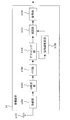
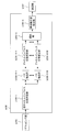
- FIG. 11 is a schematic block diagram showing the configuration of the propagation path estimation unit b206.
- the propagation path estimation unit b206 includes a temporary channel impulse response estimation unit b106-1, path extraction units b206-3-1 to b206-3-M, and channel impulse response estimation units b206-4-1 to b206-4. -M, selection section b206-6, and frequency response estimation section b106-5.
- the operations of the temporary channel impulse response estimation unit b106-1 and the frequency response estimation unit b106-5 are the same as those of the propagation path estimation unit b106 (FIG. 5) of the first embodiment. A description of the same functions as those in the first embodiment is omitted.
- the propagation path estimation unit b206 estimates M channel impulse responses. Let N S (m) be the number of extraction paths when estimating the m-th channel impulse response. The estimated number M and the extracted path number N s (m) may be fixed at the stage of development of the receiving device b2, or may be made variable at the design stage, and updated when updating the firmware, software, etc. of the receiving device b2. You may do it.
- the path extraction unit b206-3-M extracts N s (m) paths in descending order of power from the temporary channel impulse response estimation values output from the temporary channel impulse response estimation unit b106-1.
- the processing flow of the temporary channel impulse response estimation unit b206-1-M to the channel impulse response estimation unit b206-4-M is the same as that of the temporary channel impulse response estimation unit b106-1 to channel impulse response estimation unit b106 in the first embodiment. -4 (FIG. 5). However, the number of extraction paths is N s (m).
- the selection unit b206-6 compares the M channel impulse response estimation values estimated by the channel impulse response estimation units b206-4-1 to b206-4-M, selects the best one, and selects the best frequency response estimation unit b106. Output to -5. This process will be described later together with the operation principle.
- the frequency response estimation unit b106-5 performs time-frequency conversion on the channel impulse response estimation value output from the selection unit b206-6 to convert it into a frequency response estimation value for demodulation, and outputs it to the demodulation unit b107.
- the channel impulse response estimation unit b206-4-M outputs the channel impulse response estimation value.
- the first term is an evaluation value of the error between the temporary channel impulse response and the channel impulse response
- the second term is a penalty for increasing the number of estimated paths.
- the equation (21) is an example of an amount indicating an error evaluation value and a goodness due to a penalty, and other criteria such as an AIC including an error evaluation value and a penalty may be used.
- the selection unit b206-6 selects the channel impulse response estimation value corresponding to m that maximizes f (m).
- FIG. 12 is a flowchart showing the operation of the receiving apparatus according to this embodiment. The operation shown in this figure is processing after the reception unit b102 in FIG. 10 outputs the reception signal to the GI removal unit b103.
- Step S201 The GI removing unit b103 removes the GI from the received signal. Thereafter, the process proceeds to step S202.
- Step S202 The FFT unit b104 performs time-frequency conversion on the signal obtained in Step S201.
- the demapping unit b105 separates data and pilot from the obtained frequency domain signal. After outputting the reception signal of the pilot subcarrier to the propagation path estimation unit b206, the process proceeds to step S203.
- Step S203 The temporary channel impulse response estimation unit b106-1 in the propagation path estimation unit b206 calculates a temporary channel impulse response estimation value using the received signal of the pilot subcarrier obtained in step S202. After the estimated value is output to the path extraction units b206-3-1 to b206-3-M, the process proceeds to step S204.
- Step S204 The path extraction unit b206-3-M performs path extraction using the temporary channel impulse response estimation value obtained in step S203, and outputs the result to the channel impulse response estimation unit b206-4-M. Thereafter, the process proceeds to step S205.
- Step S205 The channel impulse response estimation unit b206-4-M calculates a channel impulse response estimated value using the path information obtained in step S204. Thereafter, the process proceeds to step S206.
- Step S206 The selection unit b206-6 compares the M channel impulse response estimation values obtained in step S205, selects the best one, and outputs it to the frequency response estimation unit b106-5. Thereafter, the process proceeds to step S207.
- Step S207 The frequency response estimation unit b106-5 performs time-frequency conversion on the channel impulse response estimation value obtained in Step S206, and converts it to a frequency response estimation value. Thereafter, the process proceeds to step S208.
- Step S208 The demodulation unit b107 performs demodulation processing using the frequency response estimation value obtained in Step S207. Thereafter, the process proceeds to step S209.
- Step S209 The decoding unit b108 performs decoding using the demodulation result obtained in step S208. Thereafter, the receiving device b2 ends the operation.
- the propagation path estimation unit b206 calculates the temporary channel impulse response estimated value by performing IFFT on the frequency response estimated value of the pilot subcarrier, extracts the path with the higher power, A channel impulse response estimation value is calculated using the path information.
- channel impulse response estimation values obtained by using a plurality of extraction paths are compared, and the best one is selected. In this way, the degree of freedom can be used for noise / interference suppression as much as the estimation unnecessary path is not used, and the propagation path estimation accuracy can be improved.
- the transmission device a1 transmits a multicarrier signal or the like that maps pilot symbols in the frequency domain, and the reception devices b1 and b2 calculate frequency response estimation values in pilot subcarriers. Then, IFFT is used to calculate a provisional channel impulse response estimated value, and a plurality of processes of extracting a path having a large power among them are performed, and the best one is selected, and the channel using the selected extraction path is selected. Impulse response was calculated. In this embodiment, first, all the paths from the preceding path to the assumed maximum delay time are estimated, and from there, the process of reducing the number of paths is performed. adopt.
- the transmission apparatus according to the third embodiment of the present invention is the same as the transmission apparatus a1 according to the first embodiment, description thereof is omitted.
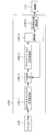
- FIG. 13 is a schematic block diagram showing the configuration of the receiving device b3 according to the third embodiment of the present invention.
- the processing of the propagation path estimation unit b306 is different.
- the functions of other components (receiving antenna b101, receiving unit b102, GI removing unit b103, FFT unit b104, demapping unit b105, demodulating unit b107, decoding unit b108) are the same as those in the first embodiment. .
- a description of the same functions as those in the first embodiment is omitted.
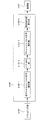
- FIG. 14 is a schematic block diagram showing the configuration of the propagation path estimation unit b306.
- the operations of the path extracting unit b306-3 and the channel impulse response estimating unit b306-4 are as follows. Differently, a selection unit b306-6 is added.
- the operations of the temporary channel impulse response estimation unit b106-1 and the frequency response estimation unit b106-5 are the same as those of the propagation path estimation unit b106 (FIG. 5) of the first embodiment. A description of the same functions as those in the first embodiment is omitted.
- the propagation path estimation unit b306 repeats the operations of the path extraction unit b306-3, the channel impulse response estimation unit b306-4, and the selection unit b306-6 until the best result is obtained.
- the path extraction unit b306-3 sets the number of first extracted paths from the preceding path to the assumed maximum delay time L. As in the first embodiment, this value may be fixed when the receiving device b3 is developed, or may be changed at the design stage, and updated when the firmware, software, etc. of the receiving device b3 are updated. May be. In iterative process, from the previous extraction path number, the number of reduced N i pass the extracted path number.
- the channel impulse response estimation unit b306-4 calculates a channel impulse response estimation value based on the path position information output from the path extraction unit b306-3.
- the selection unit b306-6 performs no operation at the first time, and issues a command to reduce the number of extracted paths to the path extraction unit. Further, the channel impulse response estimation value output from the channel impulse response estimation unit b306-4 is stored. In the iterative process, the channel impulse response estimation value output from the channel impulse response estimation unit b306-4 and the channel impulse response estimation value stored in the selection unit b306-6 are compared based on Expression (21). As a result, if the stored value is better, the estimation process ends here, and the stored channel impulse response estimated value is output to the frequency response estimating unit b106-5. If the stored value is worse, issue an instruction to reduce the number of extracted paths to the path extraction unit, store the channel impulse response estimation value that is the output of the channel impulse response estimation unit b306-4, and continue the iterative process To do.
- channel impulse response estimation section b306-4 calculates a channel impulse response estimation value based on the path information. Estimate value for k-th trial
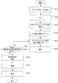
- FIG. 15 is a flowchart showing the operation of the receiving apparatus according to this embodiment. The operation shown in this figure is a process after the reception unit b102 in FIG. 13 outputs the reception signal to the GI removal unit b103.
- Step S301 The GI removing unit b103 removes the GI from the received signal. Thereafter, the process proceeds to step S302.
- Step S302 The FFT unit b104 performs time-frequency conversion on the signal obtained in Step S301.
- the demapping unit b105 separates data and pilot from the obtained frequency domain signal. After the reception signal of the pilot subcarrier is output to the propagation path estimation unit b106, the process proceeds to step S303.
- Step S303 The temporary channel impulse response estimation unit b106-1 in the propagation path estimation unit b306 calculates a temporary channel impulse response estimation value using the received signal of the pilot subcarrier obtained in step S302. After the estimated value is output to the path extraction unit b306-3, the process proceeds to step S304.
- Step S304 The path extraction unit b306-3 performs path extraction using the temporary channel impulse response estimation value obtained in step S303, and outputs the result to the channel impulse response estimation unit b306-4. Thereafter, the process proceeds to step S305.
- Step S305 The channel impulse response estimation unit b306-4 calculates a channel impulse response estimation value using the path information obtained in step S304. Thereafter, the process proceeds to step S306.
- Step S306 The selection unit b306-6 compares the channel impulse response estimation value obtained in step S305 with the channel impulse response estimation value stored in the selection unit b306-6. Thereafter, the process proceeds to step S307.
- Step S307 As a result of Step S306, if the channel impulse response estimated value obtained in Step S305 is better than the channel impulse response estimated value stored in the selecting unit b306-6, the selecting unit b306-6 stores The channel impulse response estimated value being discarded is discarded, and the channel impulse response estimated value obtained in step S305 is stored. In addition, the number of extraction paths of the path extraction unit b306-3 is decreased. Thereafter, the process proceeds to step S305.
- the channel impulse response estimation value stored in the selection unit b306-6 is output to the frequency response estimation unit b106-5, and the process proceeds to step S308.
- Step S308 The frequency response estimation unit b106-5 performs time-frequency conversion on the channel impulse response estimated value obtained in Step S307, and converts it to a frequency response estimated value. Thereafter, the process proceeds to step S309.
- Step S309 The demodulation unit b107 performs demodulation processing using the channel impulse response estimated value obtained in Step S308. Thereafter, the process proceeds to step S310.
- Step S310 The decoding unit b108 performs decoding using the demodulation result obtained in step S309. Thereafter, the receiving device b3 ends the operation.
- the propagation path estimation unit b306 calculates the provisional channel impulse response estimated value by performing the IFFT on the frequency response estimated value of the pilot subcarrier, and from the preceding path to the assumed maximum delay first. Calculate the channel impulse response estimate using all the paths, then repeat the calculation of the channel impulse response estimate with the number of paths reduced, finish the process with the best number of paths, and obtain the best channel impulse response estimate. obtain. In this way, the degree of freedom can be used for noise / interference suppression as much as the estimation unnecessary path is not used, and the propagation path estimation accuracy can be improved. In the present embodiment, since the optimal number of paths can be determined adaptively to the environment, it is possible to cope with changes in the environment at a high level.
- the method of sequentially repeating the calculation of the channel impulse response estimation value while reducing the number of extraction paths has been described.
- the number may be increased from a small number.
- the channel impulse response estimation value is calculated with a small number of extracted paths, and the number of extracted paths is increased in the process of being repeated thereafter.
- the method for sequentially repeating the calculation of the channel impulse response estimation value while reducing the number of extraction paths has been described.
- the method may be stopped halfway.
- the maximum number of repetitions is determined in advance, and when that number is reached, the process proceeds to step S308 regardless of the result of step S307.
- a part of the transmission device a1 and the reception devices b1 to b3, for example, the propagation path estimation unit b106 and the demodulation unit b107 in the above-described embodiment may be realized by a computer.
- the program for realizing the control function may be recorded on a computer-readable recording medium, and the program recorded on the recording medium may be read into the computer system and executed.
- the “computer system” here is a computer system built in the transmission device a1 or the reception devices b1 to b3, and includes an OS and hardware such as peripheral devices.
- the “computer-readable recording medium” refers to a storage device such as a portable medium such as a flexible disk, a magneto-optical disk, a ROM, and a CD-ROM, and a hard disk built in the computer system.
- the “computer-readable recording medium” is a medium that dynamically holds a program for a short time, such as a communication line when transmitting a program via a network such as the Internet or a communication line such as a telephone line,
- a volatile memory inside a computer system that serves as a server or a client may be included that holds a program for a certain period of time.
- the program may be a program for realizing a part of the functions described above, and may be a program capable of realizing the functions described above in combination with a program already recorded in a computer system.
- a part or all of the transmission device a1 and the reception devices b1 to b3 in the above-described embodiment may be realized as an integrated circuit such as an LSI (Large Scale Integration).
- LSI Large Scale Integration
- Each functional block of the transmission device a1 and the reception devices b1 to b3 may be individually made into a processor, or a part or all of them may be integrated into a processor.
- the method of circuit integration is not limited to LSI, and may be realized by a dedicated circuit or a general-purpose processor. Further, in the case where an integrated circuit technology that replaces LSI appears due to progress in semiconductor technology, an integrated circuit based on the technology may be used.
- a1 Transmitting device a101 Pilot generating unit a102 Encoding unit a103 Modulating unit a104 Mapping unit a105 IFFT unit a106 GI inserting unit a107 Transmitting / receiving unit a108 Transmitting antenna b1, b2, b3 Receiving device b101 Receiving antenna b102 Receiving unit b103 GI removing unit b104 FFT unit b105 Demapping unit b106, b206, b306 Propagation path estimation unit b107 Demodulation unit b108 Decoding unit b106-1 Temporary channel impulse response estimation unit b106-3, b206-3-1 to b206-3-M, b306-3 Path extraction unit b106 -4, b206-4-1 to b206-4-M, b306-4 Channel impulse response estimator b106-5 Frequency response estimator b206-6, b306-6 Selector All publications cited in this specification, Patents and patents issued As it is intended to incorporate herein by reference.
Landscapes
- Engineering & Computer Science (AREA)
- Power Engineering (AREA)
- Computer Networks & Wireless Communication (AREA)
- Signal Processing (AREA)
- Noise Elimination (AREA)
Priority Applications (1)
| Application Number | Priority Date | Filing Date | Title |
|---|---|---|---|
| US13/982,912 US8948317B2 (en) | 2011-02-03 | 2012-01-13 | Receiver apparatus, reception method, communication system, and communication method |
Applications Claiming Priority (2)
| Application Number | Priority Date | Filing Date | Title |
|---|---|---|---|
| JP2011021528A JP2012165040A (ja) | 2011-02-03 | 2011-02-03 | 受信装置、受信方法、通信システムおよび通信方法 |
| JP2011-021528 | 2011-02-03 |
Publications (1)
| Publication Number | Publication Date |
|---|---|
| WO2012105291A1 true WO2012105291A1 (ja) | 2012-08-09 |
Family
ID=46602512
Family Applications (1)
| Application Number | Title | Priority Date | Filing Date |
|---|---|---|---|
| PCT/JP2012/050548 Ceased WO2012105291A1 (ja) | 2011-02-03 | 2012-01-13 | 受信装置、受信方法、通信システムおよび通信方法 |
Country Status (3)
| Country | Link |
|---|---|
| US (1) | US8948317B2 (enExample) |
| JP (1) | JP2012165040A (enExample) |
| WO (1) | WO2012105291A1 (enExample) |
Cited By (3)
| Publication number | Priority date | Publication date | Assignee | Title |
|---|---|---|---|---|
| WO2013061900A1 (ja) * | 2011-10-25 | 2013-05-02 | シャープ株式会社 | 受信装置、受信方法、通信システムおよび通信方法 |
| JP2015115905A (ja) * | 2013-12-13 | 2015-06-22 | 日本放送協会 | 受信装置 |
| CN115987721A (zh) * | 2022-12-06 | 2023-04-18 | 华南理工大学 | 一种基于变分贝叶斯学习的信道脉冲噪声估计方法 |
Families Citing this family (9)
| Publication number | Priority date | Publication date | Assignee | Title |
|---|---|---|---|---|
| US8233554B2 (en) | 2010-03-29 | 2012-07-31 | Eices Research, Inc. | Increased capacity communications for OFDM-based wireless communications systems/methods/devices |
| US8670493B2 (en) * | 2005-06-22 | 2014-03-11 | Eices Research, Inc. | Systems and/or methods of increased privacy wireless communications |
| USRE47633E1 (en) | 2005-06-22 | 2019-10-01 | Odyssey Wireless Inc. | Systems/methods of conducting a financial transaction using a smartphone |
| US9374746B1 (en) | 2008-07-07 | 2016-06-21 | Odyssey Wireless, Inc. | Systems/methods of spatial multiplexing |
| KR102200811B1 (ko) * | 2014-05-09 | 2021-01-11 | 삼성전자 주식회사 | 복합 변조 방식을 사용하는 무선 통신 시스템에서 복합 변조 심볼의 복조 장치 및 방법 |
| KR102190933B1 (ko) * | 2014-11-20 | 2020-12-14 | 삼성전자주식회사 | 통신 시스템에서 수신기 스위칭 장치 및 방법 |
| WO2016203719A1 (ja) | 2015-06-17 | 2016-12-22 | パナソニック インテレクチュアル プロパティ コーポレーション オブ アメリカ | 送信方法、受信方法、送信装置、及び受信装置 |
| JP2017011682A (ja) * | 2015-06-17 | 2017-01-12 | パナソニック インテレクチュアル プロパティ コーポレーション オブ アメリカPanasonic Intellectual Property Corporation of America | 送信方法、受信方法、送信装置、及び受信装置 |
| JP2020191578A (ja) * | 2019-05-23 | 2020-11-26 | 日本電気株式会社 | 受信機、受信方法、及び、受信プログラム |
Citations (6)
| Publication number | Priority date | Publication date | Assignee | Title |
|---|---|---|---|---|
| JPH0575568A (ja) * | 1991-01-17 | 1993-03-26 | Fr Telecom | 通信路の周波数応答の評価と限界判定を備えた時間周波数領域に多重化されたデイジタルデータをコヒレント復調するための装置 |
| JP2007519368A (ja) * | 2004-01-21 | 2007-07-12 | クゥアルコム・インコーポレイテッド | 過剰な遅延広がりを有するofdmシステムのためのパイロット送信及びチャネル推定 |
| JP2008072387A (ja) * | 2006-09-13 | 2008-03-27 | Oki Electric Ind Co Ltd | 等化器及び等化方法 |
| JP2008118194A (ja) * | 2006-10-31 | 2008-05-22 | Oki Electric Ind Co Ltd | 等化器 |
| JP2010124368A (ja) * | 2008-11-21 | 2010-06-03 | Semiconductor Technology Academic Research Center | ドップラー周波数推定装置、受信装置、プログラム、及びドップラー周波数推定方法 |
| JP2010199902A (ja) * | 2009-02-24 | 2010-09-09 | Kyocera Corp | 無線基地局および送信電力制御方法 |
Family Cites Families (4)
| Publication number | Priority date | Publication date | Assignee | Title |
|---|---|---|---|---|
| US5955992A (en) * | 1998-02-12 | 1999-09-21 | Shattil; Steve J. | Frequency-shifted feedback cavity used as a phased array antenna controller and carrier interference multiple access spread-spectrum transmitter |
| US7548506B2 (en) * | 2001-10-17 | 2009-06-16 | Nortel Networks Limited | System access and synchronization methods for MIMO OFDM communications systems and physical layer packet and preamble design |
| US8392811B2 (en) * | 2008-01-07 | 2013-03-05 | Qualcomm Incorporated | Methods and systems for a-priori decoding based on MAP messages |
| US8279954B2 (en) * | 2008-03-06 | 2012-10-02 | Ntt Docomo, Inc. | Adaptive forward-backward soft output M-algorithm receiver structures |
-
2011
- 2011-02-03 JP JP2011021528A patent/JP2012165040A/ja active Pending
-
2012
- 2012-01-13 WO PCT/JP2012/050548 patent/WO2012105291A1/ja not_active Ceased
- 2012-01-13 US US13/982,912 patent/US8948317B2/en active Active
Patent Citations (6)
| Publication number | Priority date | Publication date | Assignee | Title |
|---|---|---|---|---|
| JPH0575568A (ja) * | 1991-01-17 | 1993-03-26 | Fr Telecom | 通信路の周波数応答の評価と限界判定を備えた時間周波数領域に多重化されたデイジタルデータをコヒレント復調するための装置 |
| JP2007519368A (ja) * | 2004-01-21 | 2007-07-12 | クゥアルコム・インコーポレイテッド | 過剰な遅延広がりを有するofdmシステムのためのパイロット送信及びチャネル推定 |
| JP2008072387A (ja) * | 2006-09-13 | 2008-03-27 | Oki Electric Ind Co Ltd | 等化器及び等化方法 |
| JP2008118194A (ja) * | 2006-10-31 | 2008-05-22 | Oki Electric Ind Co Ltd | 等化器 |
| JP2010124368A (ja) * | 2008-11-21 | 2010-06-03 | Semiconductor Technology Academic Research Center | ドップラー周波数推定装置、受信装置、プログラム、及びドップラー周波数推定方法 |
| JP2010199902A (ja) * | 2009-02-24 | 2010-09-09 | Kyocera Corp | 無線基地局および送信電力制御方法 |
Cited By (4)
| Publication number | Priority date | Publication date | Assignee | Title |
|---|---|---|---|---|
| WO2013061900A1 (ja) * | 2011-10-25 | 2013-05-02 | シャープ株式会社 | 受信装置、受信方法、通信システムおよび通信方法 |
| US8983007B2 (en) | 2011-10-25 | 2015-03-17 | Sharp Kabushiki Kaisha | Receiver apparatus, reception method, communication system, and communication method |
| JP2015115905A (ja) * | 2013-12-13 | 2015-06-22 | 日本放送協会 | 受信装置 |
| CN115987721A (zh) * | 2022-12-06 | 2023-04-18 | 华南理工大学 | 一种基于变分贝叶斯学习的信道脉冲噪声估计方法 |
Also Published As
| Publication number | Publication date |
|---|---|
| US8948317B2 (en) | 2015-02-03 |
| JP2012165040A (ja) | 2012-08-30 |
| US20130308733A1 (en) | 2013-11-21 |
Similar Documents
| Publication | Publication Date | Title |
|---|---|---|
| WO2012105291A1 (ja) | 受信装置、受信方法、通信システムおよび通信方法 | |
| JP5400857B2 (ja) | Ldpc復号化のための装置、方法、および受信端末 | |
| WO2011111583A1 (ja) | 受信装置、受信方法、受信プログラム、及びプロセッサ | |
| JP5539832B2 (ja) | 受信装置、受信方法、受信プログラム | |
| JP5428788B2 (ja) | 受信装置、受信方法、及び受信プログラム | |
| JP2013168853A (ja) | 受信装置、受信方法および受信プログラム | |
| JP2009049491A (ja) | 受信装置、受信方法及びプログラム | |
| JP4352035B2 (ja) | Ofdm復調装置、方法およびプログラム | |
| JP5371722B2 (ja) | 受信装置、受信方法、及び受信プログラム | |
| JP6272583B1 (ja) | 通信装置および受信信号処理方法 | |
| JP5788088B2 (ja) | 受信装置および受信方法 | |
| JP5837797B2 (ja) | 受信装置、受信方法、通信システムおよび通信方法 | |
| JP2013223177A (ja) | 受信装置、受信方法および受信プログラム | |
| WO2011158727A1 (ja) | 無線通信装置、受信方法およびそのプログラム | |
| WO2014175430A1 (ja) | 受信装置、受信方法および受信プログラム | |
| WO2012011399A1 (ja) | 受信装置および受信方法 | |
| JP2012253688A (ja) | 受信装置、受信方法、制御プログラムおよび集積回路 | |
| JP2014068094A (ja) | 受信装置、受信方法およびプログラム | |
| JP2010278850A (ja) | 受信装置、受信方法、及び受信プログラム | |
| JP2009272726A (ja) | 通信システム、受信装置及び通信方法 | |
| JP2018011094A (ja) | 受信装置、受信方法および集積回路 |
Legal Events
| Date | Code | Title | Description |
|---|---|---|---|
| 121 | Ep: the epo has been informed by wipo that ep was designated in this application |
Ref document number: 12742669 Country of ref document: EP Kind code of ref document: A1 |
|
| WWE | Wipo information: entry into national phase |
Ref document number: 13982912 Country of ref document: US |
|
| NENP | Non-entry into the national phase |
Ref country code: DE |
|
| 122 | Ep: pct application non-entry in european phase |
Ref document number: 12742669 Country of ref document: EP Kind code of ref document: A1 |