WO2011111583A1 - 受信装置、受信方法、受信プログラム、及びプロセッサ - Google Patents
受信装置、受信方法、受信プログラム、及びプロセッサ Download PDFInfo
- Publication number
- WO2011111583A1 WO2011111583A1 PCT/JP2011/054754 JP2011054754W WO2011111583A1 WO 2011111583 A1 WO2011111583 A1 WO 2011111583A1 JP 2011054754 W JP2011054754 W JP 2011054754W WO 2011111583 A1 WO2011111583 A1 WO 2011111583A1
- Authority
- WO
- WIPO (PCT)
- Prior art keywords
- signal
- unit
- replica
- time
- fft
- Prior art date
Links
Images

Classifications
-
- H—ELECTRICITY
- H04—ELECTRIC COMMUNICATION TECHNIQUE
- H04L—TRANSMISSION OF DIGITAL INFORMATION, e.g. TELEGRAPHIC COMMUNICATION
- H04L25/00—Baseband systems
- H04L25/02—Details ; arrangements for supplying electrical power along data transmission lines
- H04L25/03—Shaping networks in transmitter or receiver, e.g. adaptive shaping networks
- H04L25/03006—Arrangements for removing intersymbol interference
-
- H—ELECTRICITY
- H04—ELECTRIC COMMUNICATION TECHNIQUE
- H04B—TRANSMISSION
- H04B17/00—Monitoring; Testing
- H04B17/30—Monitoring; Testing of propagation channels
- H04B17/309—Measuring or estimating channel quality parameters
-
- H—ELECTRICITY
- H04—ELECTRIC COMMUNICATION TECHNIQUE
- H04B—TRANSMISSION
- H04B17/00—Monitoring; Testing
- H04B17/30—Monitoring; Testing of propagation channels
- H04B17/309—Measuring or estimating channel quality parameters
- H04B17/345—Interference values
-
- H—ELECTRICITY
- H04—ELECTRIC COMMUNICATION TECHNIQUE
- H04B—TRANSMISSION
- H04B17/00—Monitoring; Testing
- H04B17/30—Monitoring; Testing of propagation channels
- H04B17/391—Modelling the propagation channel
-
- H—ELECTRICITY
- H04—ELECTRIC COMMUNICATION TECHNIQUE
- H04L—TRANSMISSION OF DIGITAL INFORMATION, e.g. TELEGRAPHIC COMMUNICATION
- H04L25/00—Baseband systems
- H04L25/02—Details ; arrangements for supplying electrical power along data transmission lines
- H04L25/03—Shaping networks in transmitter or receiver, e.g. adaptive shaping networks
- H04L25/03006—Arrangements for removing intersymbol interference
- H04L2025/0335—Arrangements for removing intersymbol interference characterised by the type of transmission
- H04L2025/03375—Passband transmission
- H04L2025/03414—Multicarrier
Definitions
- the present invention relates to a receiving device, a receiving method, a receiving program, and a processor.
- This application claims priority on March 08, 2010 based on Japanese Patent Application No. 2010-050849 filed in Japan, the contents of which are incorporated herein by reference.
- a path that arrives with a delay such as through reflection from an obstacle such as a building or a mountain
- ISI Inter Symbol Interference
- An environment in which a plurality of paths arrives in this way is called a multipath environment.
- OFDM Orthogonal Frequency Division Multiplexing
- OFDMA Orthogonal Frequency Division Multiple Access
- MC-CDM Multi-Culcode Multiple Code
- GI Guard Interval
- GI Guard Interval
- Non-Patent Document 1 describes a technique for reducing ISI and ICI using turbo equalization. Specifically, in Non-Patent Document 1, a replica of a transmission signal is created from a bit log likelihood ratio (LLR) of an error correction decoding result, and a plurality of multipaths constituting a reception signal are used by using the replica of the transmission signal. By dividing only the desired signal in the frequency domain and suppressing ISI and ICI, it is possible to realize good reception quality.
- LLR bit log likelihood ratio
- Non-Patent Document 1 converts a plurality of blocks into the frequency domain, there is a problem that the number of FFTs is large and the calculation amount increases.
- the present invention has been made in view of the above points, and provides a receiving device, a receiving method, a receiving program, and a processor that can obtain good receiving characteristics while suppressing an increase in calculation amount and circuit scale.
- the present invention has been made to solve the above problems, and one aspect of the present invention is a time domain obtained from a received signal and a bit log likelihood ratio obtained by at least one reception process. Using a received signal replica that is a replica of the received signal, a signal in an arbitrary time interval is extracted, and the extracted signal is time-frequency converted to obtain each subcarrier signal of the received signal in which at least inter-carrier interference is suppressed.
- a receiving apparatus comprising a signal extraction unit.
- a propagation path estimation unit that performs propagation path estimation to obtain a propagation path estimation value, and a symbol that is a replica of a modulation symbol from the bit log likelihood ratio
- a symbol replica generation unit that generates a replica, wherein the signal extraction unit is configured to generate the reception signal replica based on the propagation path estimation value and the symbol replica, and to receive the signal from the reception signal.
- a subtracting unit that subtracts a signal replica, and an extended FFT section that extracts an extended FFT section signal that is a signal of a time section of an arbitrary length from the signal subtracted by the subtracting section and generates an FFT signal from the extended FFT section signal
- An extraction unit a time-frequency conversion unit that converts the FFT signal into a frequency-domain signal, a subchannel based on the propagation path estimation value and the symbol replica
- a recovery unit that generates a carrier replica signal, adds the subcarrier replica signal to the frequency domain signal converted by the time-frequency conversion unit, and obtains each subcarrier signal of the received signal, To do.
- a propagation path estimation unit that performs propagation path estimation to obtain a propagation path estimation value, and a symbol that is a replica of a modulation symbol from the bit log likelihood ratio
- a symbol replica generation unit that generates a replica, wherein the signal extraction unit generates the received signal replica based on the propagation path estimation value and the symbol replica, and a signal in an arbitrary time interval
- An extended FFT section signal that is extracted from the extended FFT section signal and generates an FFT section signal, a first FFT section signal generated from the received signal, and the received signal replica.
- a time-frequency converter for converting the second FFT interval signal into a frequency domain signal, and the frequency domain from the first FFT interval signal in the frequency domain.
- a subcarrier replica signal is generated based on the subtraction unit for subtracting the second FFT interval signal, the propagation path estimation value and the symbol replica, and the subcarrier replica signal is subtracted from the signal subtracted by the subtraction unit.
- a restoration unit that adds and extracts each subcarrier component of the received signal in an arbitrary time interval.
- the filter unit in the reception apparatus, the filter unit generates the reception signal replica based on a symbol replica subjected to frequency-time conversion and the propagation path estimation value.
- a section length of the extended FFT section signal is longer than that of the FFT section signal.
- the FFT interval signal includes a signal having a length equal to or longer than the FFT interval signal in the extended FFT interval signal.
- a start position of a time section of the extended FFT section signal is different from a start position of the time section of the FFT section signal.
- the start position of the time interval of the extended FFT interval signal is the same as the start position of the time interval of the FFT interval signal.
- the extended FFT section signal has a leading end of a preceding path at a beginning of a time section for extracting a signal and a maximum delay path at the end of the time section. It is the rear end of the signal.
- the extended FFT section extraction unit multiplies the extracted signal section by a window function.
- the restoration unit extracts a subcarrier component of a frequency domain signal converted by the time-frequency conversion unit, and extracts the extracted subcarrier component signal In contrast, the subcarrier component of the replica signal of the desired signal is added.
- the restoration unit extracts a subcarrier component of the frequency domain signal converted by the time-frequency conversion unit, and extracts the extracted subcarrier component signal.
- a subcarrier component of the replica signal of the desired signal and a subcarrier component close to the subcarrier is added.
- One embodiment of the present invention is characterized in that, in the above-described receiving device, the receiving device includes a plurality of antennas, and the receiving device performs MIMO transmission communication with the transmitting device.
- One embodiment of the present invention is characterized in that, in the above-described receiving apparatus, the demodulator performs MIMO separation based on the propagation path estimation value.
- the reception device receives a stream signal that is a signal sequence transmitted from each of a plurality of antennas included in the transmission device as the reception signal.
- the signal extraction unit generates a received signal replica that is a replica of the received signal in the time domain based on the propagation path estimation value and the symbol replica; and the received signal replica from the received signal.
- a subtracting section for subtracting, an extended FFT section extracting section for extracting a signal of a time section of an arbitrary length from the signal subtracted by the subtracting section, and a signal of the time section extracted by the extended FFT section extracting section in the frequency domain Generating a replica signal of a desired signal based on the propagation path estimated value and the symbol replica, and converting the time frequency
- a restoration unit that adds a replica signal of the desired signal to the frequency domain signal converted by the conversion unit and extracts each subcarrier component of the received signal in a time interval of an arbitrary length, and The unit extracts a subcarrier component of the frequency domain signal converted by the time frequency conversion unit, and extracts a desired stream from the subcarrier components of the replica signal of the desired signal with respect to the extracted subcarrier component signal. The components are added.
- the reception device receives a stream signal that is a signal sequence transmitted from each of a plurality of antennas included in the transmission device as the reception signal.
- the signal extraction unit generates a received signal replica that is a replica of the received signal in the time domain based on the propagation path estimation value and the symbol replica; and the received signal replica from the received signal.
- a subtracting section for subtracting, an extended FFT section extracting section for extracting a signal of a time section of an arbitrary length from the signal subtracted by the subtracting section, and a signal of the time section extracted by the extended FFT section extracting section in the frequency domain Generating a replica signal of a desired signal based on the propagation path estimation value and the symbol replica, and converting the time frequency
- a restoration unit that adds a replica signal of the desired signal to the frequency domain signal converted by the conversion unit and extracts each subcarrier component of the received signal in a time interval of an arbitrary length, and The unit extracts a subcarrier component of the frequency domain signal converted by the time frequency conversion unit, and for all the subcarrier components of the replica signal of the desired signal for the extracted subcarrier component signal, The components are added.
- the demodulator demodulates a signal based on a minimum mean square error criterion.
- the signal extraction unit is a received signal replica that is a replica of the received signal in the time domain obtained from the received signal and a bit log likelihood ratio obtained by at least one reception process.
- a reception signal that is a replica of a reception signal in a time domain obtained from a reception signal and a bit log likelihood ratio obtained by at least one reception process is performed on the computer of the reception device.
- a reception program that extracts a signal in an arbitrary time interval using a replica, functions as a signal extraction means for obtaining each subcarrier signal of a reception signal in which at least inter-carrier interference is suppressed by performing time-frequency conversion on the extracted signal is there.
- One embodiment of the present invention uses a received signal replica that is a replica of a received signal in a time domain obtained from a received signal and a bit log likelihood ratio obtained by at least one reception process.
- a processor that obtains each subcarrier signal of a received signal in which at least inter-carrier interference is suppressed by extracting a signal in a time interval of (2) and performing time-frequency conversion on the extracted signal.
- the FFT interval is longer than usual.
- it is a receiving method characterized by having the process of calculating
- FIG. 1 is a schematic block diagram of a transmission device according to a first embodiment of the present invention. It is a schematic block diagram which shows the structure of the receiver which concerns on this embodiment. It is the schematic which shows an example of the received signal which concerns on this embodiment. It is the schematic which shows an example of the FFT area which the receiver which concerns on this embodiment selects. It is a flowchart which shows operation
- the transmission device a1 and the reception device b1 perform communication.
- FIG. 1 is a schematic block diagram of a transmission device a1 according to the first embodiment of the present invention.
- the transmission device a1 includes a pilot generation unit a101, a coding unit a102, a modulation unit a103, a mapping unit a104, an IFFT unit a105, a GI insertion unit a106, a transmission unit a107, and a transmission antenna unit a108. .
- the pilot generation unit a101 generates a pilot signal in which the reception apparatus stores in advance the amplitude value of the waveform (or the signal sequence), and outputs the pilot signal to the mapping unit a104.
- the receiving device is referred to as b1.
- the encoding unit a102 encodes information bits to be transmitted to the receiving apparatus b1 using an error correction code such as a convolutional code, a turbo code, and an LDPC (Low Density Parity Check) code, and encodes the encoded bits. Is generated.
- the encoding unit a102 outputs the generated encoded bits to the modulating unit a103.
- the modulation unit a103 modulates the coded bits input from the coding unit a102 using a modulation scheme such as PSK (Phase Shift Keying) or QAM (Quadrature Amplitude Modulation). Generate a symbol. Modulation section a103 outputs the generated modulation symbol to mapping section a104.
- a modulation scheme such as PSK (Phase Shift Keying) or QAM (Quadrature Amplitude Modulation).
- the mapping unit a104 maps the pilot signal input from the pilot generation unit a101 and the modulation symbol input from the modulation unit a103 to a resource (time-frequency band) based on predetermined mapping information, and performs frequency domain And the generated frequency domain signal is output to the IFFT unit a105.
- a resource is a unit in which a modulation symbol is arranged, which is composed of one subcarrier and one later-described FFT interval in a frame transmitted by the transmission apparatus a1.
- the mapping information is determined by the transmission device a1, and is notified in advance from the transmission device a1 to the reception device b1.
- the IFFT unit a105 frequency-time converts the frequency domain signal input from the mapping unit a104 to generate a time domain signal.
- a time interval of a unit for performing IFFT is referred to as an FFT interval.
- the IFFT unit a105 outputs the generated time domain signal to the GI insertion unit a106.
- the GI insertion unit a106 adds a guard interval for each signal in the FFT interval to the time domain signal input from the IFFT unit a105.
- the guard interval is a known signal using a cyclic prefix (CP) that is a part of the rear of the signal in the FFT interval, zero padding in which the zero interval continues, a Golay code, or the like.
- CP cyclic prefix
- the GI insertion unit a106 adds such a signal to the front of the signal in the FFT interval.
- the FFT interval and the time interval (referred to as GI interval) of the guard interval added to the signal in the time interval by the GI insertion unit a106 are collectively referred to as an OFDM symbol interval.
- a signal in the OFDM symbol section is called an OFDM symbol.
- the GI insertion unit a106 outputs a signal with the guard interval added to the transmission unit a107.
- a guard interval may be inserted behind the FFT interval.
- a part of the replica in front of the FFT interval is added behind the signal in the FFT interval.
- the periodicity may be maintained in the OFDM symbol period, and is not limited to the above.
- the transmission unit a107 performs digital / analog conversion on the signal input from the GI insertion unit a106, and shapes the waveform of the converted analog signal.
- the transmission unit a107 upconverts the waveform-shaped signal from the baseband to the radio frequency band, and transmits the signal from the transmission antenna a108 to the reception device b1.
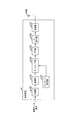
- FIG. 2 is a schematic block diagram illustrating a configuration of the receiving device b1 according to the present embodiment.
- the receiving device b1 includes a receiving antenna b101, a receiving unit b102, a subtracting unit b103, an extended FFT section extracting unit b104, an FFT unit b105, a propagation path estimating unit b106, a restoring unit b107, a demodulating unit b108, a decoding unit b109, A symbol replica generation unit b110, an IFFT unit b111, a GI insertion unit b112, and a filter unit b113 are included.
- the subtraction unit b103, the extended FFT section extraction unit b104, the FFT unit b105, the restoration unit b107, and the filter unit b113 are referred to as a signal extraction unit B1.
- the reception unit b102 receives the transmission signal transmitted by the transmission device a1 via the reception antenna b101.
- the receiving unit b102 performs frequency conversion and analog-digital conversion on the received signal.
- the receiving unit b102 stores the converted received signal.
- the reception unit b102 outputs the received signal to be stored to the subtraction unit b103 and the propagation path estimation unit b106 at the initial processing and the timing when the filter unit b113 described later inputs the reception signal replica to the subtraction unit b103.
- the subtractor b103 subtracts the received signal replica input from the filter unit b113 described later from the received signal input from the receiver b102.
- the subtractor b103 outputs a signal obtained by subtracting the received signal replica to the extended FFT section extractor b104.
- the subtracting unit b103 outputs the received signal input from the receiving unit b102 as it is to the extended FFT section extracting unit b104.
- the extended FFT section extraction unit b104 outputs a signal in a signal processing section that reduces the amount of interference to the FFT unit b105 based on the channel impulse response input from the propagation path estimation unit b106 described later. Moreover, the information which shows the extracted signal processing area is output to the propagation path estimation part b106. Details of this processing will be described later together with the operation principle.
- the FFT unit b105 performs time frequency conversion on the time domain signal input from the extended FFT section extraction unit b104, and outputs the converted frequency domain signal to the restoration unit b107.
- the propagation path estimation unit b106 estimates the channel impulse response in the OFDM symbol section based on the reception signal input from the reception unit b102 and the transmission signal replica input from the GI insertion unit b112 described later.
- an RLS (Recursive Last Square) algorithm may be used, or other algorithms such as an LMS (Least Mean Square) algorithm may be used. Good.
- LMS Least Mean Square
- the propagation path estimation unit b106 is input from the pilot signal stored in advance and the reception unit b102. Based on the received signal, a channel impulse response that varies in time in the OFDM symbol period is estimated.
- the propagation path estimation unit b106 outputs the estimated channel impulse response to the filter unit b113 and the extended FFT section extraction unit b104. Moreover, the propagation path estimation part b106 performs the time frequency conversion corresponding to the signal processing area which the information input from the extended FFT area extraction part b104 shows with respect to the estimated channel impulse response, and estimates a frequency response. The propagation path estimation unit b106 outputs the estimated frequency response to the restoration unit b107 and the demodulation unit b108. Moreover, the propagation path estimation part b106 measures a noise power and interference power in the subcarrier (it is called a pilot subcarrier) by which a pilot signal is arrange
- the restoration unit b107 For each subcarrier, the restoration unit b107 multiplies a frequency response input from the propagation path estimation unit b106 by a symbol replica input from a symbol replica generation unit b110, which will be described later, to obtain a desired signal affected by the propagation path The replica signal is generated.
- the restoration unit b107 adds the generated replica signal to the signal input from the FFT unit b105 for each subcarrier. That is, the restoration unit b107 generates a replica signal of the desired signal based on the propagation path estimation value and the symbol replica, adds the replica signal of the desired signal to the frequency domain signal converted by the FFT unit b105, Each subcarrier component of the received signal is extracted.
- the restoration unit b107 outputs a signal obtained by adding the replica signal to the demodulation unit b108.
- the restoration unit b107 outputs the signal input from the FFT unit b105 to the demodulation unit b108 as it is.
- the signal extraction unit B1 removes the received signal replica from the received signal based on the propagation path estimation value and the symbol replica, and restores the desired signal to remove the ISI and ICI (interference). Each subcarrier component is extracted.
- the demodulation unit b108 calculates a filter coefficient using a ZF (Zero Forcing) standard, an MMSE (Minimum Mean Square Error) standard, and the like, using the frequency response, noise power, and interference power input from the propagation path estimation unit b106. To do.
- the demodulator b108 compensates for fluctuations in the amplitude and phase of the signal (referred to as propagation path compensation) using the calculated filter coefficient.
- the demodulator b108 demaps the signal subjected to propagation path compensation based on the mapping information notified in advance from the transmission device a1, and performs demodulation processing on the demapped signal.
- the demodulator b108 outputs a bit log likelihood ratio (LLR) as a result of the demodulation process to the decoder b109.
- LLR bit log likelihood ratio
- the decoding unit b109 performs, for example, maximum likelihood decoding (MLD; Maximum Likelihood Decoding), maximum a posteriori probability (MAP), log-MAP, Max ⁇ on the demodulated symbols input from the demodulation unit b108.
- MLD Maximum Likelihood Decoding
- MAP maximum a posteriori probability
- log-MAP log-MAP
- Max ⁇ Max ⁇ on the demodulated symbols input from the demodulation unit b108.
- Decoding processing is performed using log-MAP, SOVA (Soft Output Viterbi Algorithm), or the like.
- the decoding unit b109 outputs the bit log likelihood ratio of the decoding result as information data bits. To do.
- the decoding unit b109 outputs the bit log likelihood ratio of the decoding result to the symbol replica generation unit b110.
- the symbol replica generation unit b110 calculates an expected value of the bit log likelihood ratio input from the decoding unit b109 and modulates the calculated expected value to generate a modulation symbol (referred to as a symbol replica).
- the symbol replica generation unit b110 maps the generated symbol replica based on the mapping information notified in advance from the transmission device a1.
- the symbol replica generation unit b110 outputs the mapped symbol replica to the restoration unit b107 and the IFFT unit b111.
- the IFFT unit b111 performs frequency time conversion on the symbol replica input from the symbol replica generation unit b110, and outputs the converted time domain replica signal to the GI insertion unit b112.
- the GI insertion unit b112 generates a transmission signal replica by adding a guard interval for each signal in the FFT interval to the replica signal input from the IFFT unit b111.
- the GI insertion unit b112 outputs the generated transmission signal replica to the propagation path estimation unit b106 and the filter unit b113.
- the filter unit b113 generates a reception signal replica based on the channel impulse response input from the propagation path estimation unit b106 and the transmission signal replica input from the GI insertion unit b112.
- the filter unit b113 outputs the generated reception signal replica to the subtraction unit b103.
- the reception device b1 repeatedly performs the processing from the subtraction unit b103 to the filter unit b113 on the same signal until the decoding unit b109 no longer detects an error or a predetermined number of times (referred to as repetition processing).
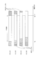
- FIG. 3 is a schematic diagram illustrating an example of a received signal according to the present embodiment. This figure shows the case where the maximum delay does not exceed the GI length and there is no interference due to the previous OFDM symbol.
- the horizontal axis is a time axis, which is discrete time divided by a predetermined time width. Also, in this figure, the hatched area with diagonal lines rising diagonally to the right indicates a guard interval. Also, the hatched area with diagonally upward left lines indicates the received signals of the preceding and following OFDM symbols.
- N is the number of points in the FFT (Fast Fourier Transform) section (also the number of points in the IFFT (Inverse Fast Fourier Transform) section), and N g is the number of GI points.
- the number of points is the number of discrete times.
- the extended FFT section extraction unit b104 inputs the extracted signal to the FFT unit b105.
- the receiving apparatus b1 can extract a signal that does not cause interference due to the preceding and succeeding OFDM symbols.
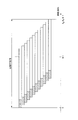
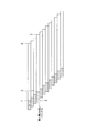
- FIG. 4 is a schematic diagram illustrating an example of an FFT interval selected by the receiving device b1 according to the present embodiment.
- This figure is a case where the maximum delay exceeds the GI length and there is interference due to the previous OFDM symbol.
- the horizontal axis is a time axis, which is discrete time divided by a predetermined time width.
- a hatched area with a diagonal line rising diagonally to the right indicates GI.
- the extended FFT section extraction unit b104 does not fix the number of points to N and selects a section that reduces interference.
- K D denotes a delay time of the maximum delay path (maximum delay time).
- This figure shows a case where the extended FFT section extraction unit b104 selects from the leading edge of the preceding wave path to the end of the maximum delay path. In this figure, there are 12 paths (including preceding wave paths) in this signal processing section.
- the extended FFT interval extraction unit b104 outputs the signal of the signal processing interval to the FFT unit b105 with the selected interval as the signal processing interval. This process will be described later together with the operation principle. Note that a section shorter than a normal FFT section may be selected as the extended FFT section.
- D is is a maximum channel number, here assumed to be equal to the maximum delay time the K D.
- H i, d, k are complex amplitudes at the k-th discrete time in the path of the channel number d of the i-th symbol (referred to as the d-th path), and s i, k are transmission signals in the time domain of the i-th symbol.
- Zi , k are noises in the time domain of the i-th symbol.
- N is the number of points in the FFT interval
- S i, n is the modulation signal of the i-th symbol of the n-th subcarrier
- N g is the number of points in the GI interval (see FIG. 4)
- j is an imaginary unit.
- equation (5) matches the discrete Fourier transform result for the time average of the channel impulse response that is time-varying within the OFDM symbol.
- the propagation path estimation unit b106 estimates W i, n, n using the pilot signal.
- the signal represented by Expression (3) is output from the FFT unit b105 to the demodulation unit b108 as it is via the restoration unit b107.
- the demodulator b108 calculates the demodulated symbol S ′ i, n using the following equation (6).
- Equation (6) ⁇ z 2 is noise power and ⁇ I 2 is ISI and ICI power, which are expressed as in the following Equations (7) and (8).
- E [X] represents an ensemble average of X.
- the propagation path estimation unit b106 calculates these powers using the pilot signal, and calculates the demodulated symbol S ′ i, n using the result in equation (6). Specifically, it is calculated as in the following equation (9).
- Equation (9) is an estimated value of ⁇ z 2 + ⁇ I 2
- P i is a set representing pilot subcarriers in the i-th symbol. Note that this is a calculation method using the fact that Equation (9) can be expressed by the following Equation (10) when it is assumed that a sufficient number of arithmetic averages is equal to the ensemble average.
- the first term represents the power of ISI and ICI
- the second term represents the noise power.
- This equation is for the case where the power of the pilot signal is normalized to 1 and the power average of the frequency response is normalized to 1. That is, this expression is a case where the following expression (11) is satisfied.
- pilot signal power is not 1, an adjustment factor corresponding to that power may be introduced. Further, the normalization of the frequency response is caused by amplitude adjustment when analog-to-digital conversion is performed in the receiving unit b102.
- the demodulator b108 calculates a bit log likelihood ratio from the demodulated symbol S ′ i, n in Equation (6).
- An equivalent amplitude gain is used for this calculation process.
- the bit log likelihood ratio ⁇ is expressed by the following equations (13) and (14) with respect to the equivalent amplitude gain ⁇ i, n of the n-th subcarrier expressed by the following equation (12). It is represented by Here, the equations (13) and (14) are respectively expressed by bit log likelihood ratios ⁇ (b i, n ) of the first bit bits b i, n, 0 and the second bit bits b i, n, 1. , 0 ), ⁇ (b i, n, 1 ).
- the symbol replica generation unit b110 calculates an expected value of the bit log likelihood ratio decoded by the decoding unit b109, and modulates the calculated expected value to generate a symbol replica S ′′ i, n .
- the symbol replica S ′′ i, n is frequency-time converted by the IFFT unit b111, and the GI is inserted by the GI insertion unit b112.
- the transmission signal replica s ′′ i, k output from the GI insertion unit b112 is expressed by the following equation (15).
- the IFFT unit b111 performs inverse fast Fourier transform, and the order of the number of multiplications in this transform is O (Nlog 2 N). is there.
- the propagation path estimation unit b106 estimates the channel impulse response h i, d, k based on the transmission signal replica expressed by the equation (15) and the reception signal input from the reception unit b102. Further, the propagation path estimation unit b106 performs time-frequency conversion after time-averaging the channel impulse responses h i, d, k to calculate the frequency responses W i, n, n .
- the filter unit b113 determines the received signal replica represented by the following equation (16). r ′′ i, k is generated.
- the order of the number of multiplications in the processing performed by the filter unit b113 to generate the received signal replica of Expression (16) is O (DN).
- D ⁇ N in general, it may be considered as O (N).
- the subtractor b103 subtracts the received signal replica r ′′ i, k represented by the equation (16) from the received signal r i, k represented by the equation (1), and the signal r represented by the following equation (17). 'Output i and k .
- the extended FFT interval extraction unit b104 determines a signal selection interval to be output to the FFT unit b105 from the estimated channel impulse response.
- the FFT unit b105 performs a fast Fourier transform.
- the order of the number of multiplications in this conversion is O (Nlog 2 N).
- the restoration unit b107 multiplies the symbol replica S ′′ i, n by the frequency response W i, n, n to obtain a replica signal W i, n, n S ′′ i, of the desired signal affected by the propagation path . n is generated.
- the restoration unit b107 adds the generated replica signal W i, n, n S ′′ i, n to the signal R ′ i, n represented by Expression (18).
- the signal Y i, n after this addition is expressed by the following equation (20).
- This equation (20) means that the desired signal of the nth subcarrier remains and the ICI is removed. By removing ICI, the signal-to-interference noise power ratio (SINR) can be improved, and the transmission characteristics are improved.
- the restoration unit b107 performs the process for generating the signal Y i, n of Expression (20) for each subcarrier, the order of the number of multiplications in this process is O (N).
- the demodulation unit b108 calculates the demodulation symbol S ′ i, n of the n-th subcarrier represented by the following equation (21) from the signal Y i, n represented by the equation (20). Then demodulate.
- the expression (21) is an expression in the case where the removal residual due to the received signal is accurately taken into consideration.
- the present invention is not limited to this, and the removal expression is converted into noise, and the following expression (22) is obtained.
- the demodulated symbol S ′ i, n may be calculated by using it.
- ⁇ I ′ 2 is the power of the ICI removal residual, and can be calculated together with the noise power by the same method as in the initial processing. In this way, even if the equation (22) is used, the characteristic deterioration is small.
- the number of multiplications of order O (N 2 ) is required for calculation of the ICI removal residual term of the second term of the denominator.
- Expression (22) processing can be performed with the number of multiplications of order O (N), and the number of multiplications can be greatly reduced. Therefore, the order of the maximum number of multiplications in each part of the iterative process is O (Nlog 2 N), and the receiving apparatus b1 can perform the iterative process by the process of the number of multiplications of order O (Nlog 2 N).
- V i, n, m, 1 and V i, n, m, 2 are ISI coefficients, the former representing the coefficient from the previous symbol and the latter representing the coefficient from the next symbol.
- the signal is output to the FFT unit b105.
- the receiving apparatus b1 can restore a signal by one conventional FFT process even when synthesizing an interval longer than a normal FFT interval.
- the restoration unit b107 multiplies the symbol replica S ′′ i, n by the frequency response W i, n, n to obtain a replica signal W i, n, n S ′′ i, of the desired signal affected by the propagation path . n is generated.
- the restoration unit b107 adds the generated replica signal W i, n, n S ′′ i, n to the signal R ′ i, n represented by the equation (23).
- the signal Y i, n after this addition is expressed by the following equation (25).
- This equation (25) means that the desired signal of the n-th subcarrier remains and the ISI and ICI are removed.
- SINR can be improved and transmission characteristics are improved by removing ISI and ICI. That is, good reception characteristics can be obtained.
- the demodulation unit b108 demodulates the demodulated symbol S of the n-th subcarrier represented by the following equation (27) from the signal Y i, n represented by the equation (25). 'Calculate i and n and demodulate.
- ⁇ I ′ 2 is the power of the ISI and ICI removal residual, and can be calculated together with the noise power by the same method as in the initial processing.
- the decoding unit b109 performs a decoding process on the bit log likelihood ratios ⁇ (b i, n, 0 ) and ⁇ (b i, n, 1 ) of the demodulated symbol S ′ i, n expressed by Expression (27). I do. Thereafter, the iterative process is repeated. By repeating the above-described iterative process, the transmission characteristics can be greatly improved.
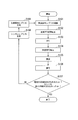
- FIG. 5 is a flowchart showing the operation of the receiving apparatus according to this embodiment. The operation shown in this figure is processing after the reception unit b102 in FIG. 2 outputs the reception signal to the subtraction unit b103 for the first time.
- Step S101 The subtraction unit b103 subtracts the reception signal replica generated in step S109 described later from the reception signal. Then, it progresses to step S102.
- Step S102 The extended FFT section extraction unit b104 extracts an FFT section in which interference is reduced from the signal resulting from the subtraction in Step S101. Thereafter, the process proceeds to step S103.
- Step S103 The FFT unit b105 performs time frequency conversion on the signal in the FFT interval extracted in Step S102. Thereafter, the process proceeds to step S104.
- Step S104 For each subcarrier, the restoration unit b107 outputs the FFT section signal extracted by the extended FFT section extraction unit b104 to the symbol replica generated in step S108 described later with respect to the signal of the conversion result in step S103. The symbol replica signal multiplied by the frequency response is added. Thereafter, the process proceeds to step S105.
- the demodulation unit b108 performs propagation path compensation on the signal resulting from the addition in step S104, and calculates a bit log likelihood ratio. Thereafter, the process proceeds to step S106.
- Step S106 The decoding unit b109 performs a decoding process such as error correction on the bit log likelihood ratio of the calculation result in step S105. Thereafter, the process proceeds to step S107.
- Step S107 The decoding unit b109 determines whether no error is detected in the decoding result in step S106, or whether a predetermined number of processes have been performed. If any of these is true (Yes), the receiving apparatus b1 ends the operation. On the other hand, when it does not correspond to both of these (No), it progresses to step S108. Note that the determination of whether or not there is an error in the decoding result may be performed, for example, in a MAC (Media Access Control) layer.
- the symbol replica generation unit b110 generates a symbol replica from the bit log likelihood ratio of the decoding result in step S106. Thereafter, the process proceeds to step S109.
- the IFFT unit b111, the GI insertion unit b112, and the filter unit b113 generate a received signal replica based on the symbol replica generated in step S108. Then, it progresses to step S101.
- the propagation path estimation part b106 estimates a propagation path estimated value.
- the symbol replica generation unit b110 generates a symbol replica that is a modulation symbol of the demodulated information.
- the signal extraction unit B1 extracts each subcarrier component of the received signal from which interference has been removed in a time interval of an arbitrary length.
- the demodulator b108 demodulates the signal of each subcarrier component of the received signal based on the signal in the time interval extracted by the signal extractor B1. As a result, the receiving device b1 can obtain good reception characteristics while suppressing an increase in calculation amount and circuit scale.
- the receiving apparatus b1 extracts each subcarrier component of the received signal from which ISI and ICI are removed, and demodulates the extracted signal of each subcarrier component. Thereby, the receiving device b1 can prevent an increase in the calculation amount. Further, not only when the delay time of the delayed wave exceeds the guard interval, it is possible to suppress ICI that occurs when the receiving apparatus moves at high speed.
- the filter unit b113 generates a reception signal replica
- the subtraction unit b103 subtracts the reception signal replica
- the restoration unit b107 adds the replica signal of the desired signal.
- demodulation processing is performed has been described.
- the filter unit b113 generates a signal replica obtained by removing the received signal of the desired signal from the received signal
- the subtracting unit b103 generates the replica signal.
- Subtraction may be performed and demodulation processing may be performed for each subcarrier.
- the above equation (17) is replaced by the following equations (28) and (29).
- the section extracted by the extended FFT section extraction unit b104 is from the leading end of the preceding wave to the end of the maximum delay path, but is not limited thereto. For example, it may be possible to extract from the front end to the end of the path with the highest power. Further, the position shown in FIG. 6 may be set as the start position or end position of the section.
- FIG. 6 is a schematic diagram illustrating an example of an FFT interval selected by a receiving apparatus according to a modification of the present embodiment. In this figure, the horizontal axis is the time axis, and the vertical axis is the path.
- the extended FFT section extraction unit b104 may use the tip obtained by removing the guard interval from the preceding wave as the start position of the extended FFT section (time indicated by reference numeral 1). Further, the extended FFT section extraction unit b104 searches, for example, from the preceding wave and starts the end of the path with the highest power (fourth path in FIG. 6) at the start position of the extended FFT section (time denoted by reference numeral 2). It may be. In addition, the extended FFT section extraction unit b104 may search, for example, from the preceding wave, and use the leading end obtained by removing the guard interval from the path with the highest power as the start position of the extended FFT section (time indicated by reference numeral 3). .
- the extended FFT section extraction unit b104 may set, for example, the rearmost position where leakage from the next OFDM symbol does not occur as the end position of the extended FFT section (time indicated by reference numeral 4). In addition, the extended FFT section extraction unit b104 searches for the last position where no leakage from the next OFDM symbol occurs with respect to the path after the path having the highest power by searching from the preceding wave, for example. May be the end position (time indicated by reference numeral 5). Note that the extended FFT section extraction unit b104 may select a predetermined path leading edge or rearmost position instead of the leading edge or rearmost position of the path with the highest power.
- the section extracted by the extended FFT section extraction unit b104 is not limited to the above range, and may be adapted to any length in the sense that the length of the FFT section is different from normal. Good. Also, it does not have to be a guard interval or signal break.
- the communication system performs communication of multicarrier signals.
- the present invention is not limited to this, and is also applicable to communication of single carrier signals using FFT. can do.
- the extended FFT section extraction unit b104 selects a corresponding extended FFT section as a signal processing section. Moreover, the case where the signal of the signal processing area selected by the receiving apparatus b1 is demodulated for each subcarrier and the information bits are decoded has been described. In this embodiment, a case will be described in which the reception device multiplies a window function before extracting a signal in an extended FFT section, and demodulates and decodes the signal using a plurality of subcarriers.
- the transmission device according to the present embodiment is the same transmission device a1 as in the first embodiment, and thus description thereof is omitted.
- the receiving device is referred to as a receiving device b2.
- FIG. 7 is a schematic block diagram showing the configuration of the receiving device b2 according to the second embodiment of the present invention.
- the receiving apparatus b2 (FIG. 7) according to the present embodiment is compared with the receiving apparatus b1 (FIG. 2) according to the first embodiment, the extended FFT section extracting unit b204, the FFT unit b205, and the propagation path of the signal extracting unit B2
- the estimation unit b206 and the restoration unit b207 are different, a window multiplication unit b209 is added, and the demodulation unit b208 is different.
- reception antenna b101, reception unit b102, subtraction unit b103, decoding unit b109, symbol replica generation unit b110, IFFT unit b111, GI insertion unit b112, and filter unit b113 are the first This is the same as the embodiment. A description of the same functions as those in the first embodiment is omitted.
- the extended FFT interval extraction unit b204 extracts the signal of the extended FFT interval based on the channel impulse response estimation value input from the propagation path estimation unit b206, which will be described later, as in the first embodiment, and sends it to the window multiplication unit b209. Output. Further, the extended FFT section extraction unit b204 outputs information indicating the extracted signal processing section to the propagation path estimation unit b206.
- the window multiplication unit b209 multiplies the output result of the extended FFT section extraction unit by a window function and outputs the result to the FFT unit b205. By multiplying the window function in this way, the receiving apparatus b2 can reduce the influence of the ISI and ICI removal residuals.
- a window function of a Hanning window is used as the window function. This process will be described together with the operation principle. Further, the window multiplier b209 outputs the multiplied window information to the propagation path estimator b206.
- the FFT unit b205 performs time frequency conversion on the time domain signal input from the window multiplication unit b209, and outputs the converted frequency domain signal to the restoration unit b207. At this time, not only the same subcarrier but also the signals of neighboring subcarriers are output for one desired subcarrier.
- the FFT unit b205 is different from the FFT unit b105 (see FIG. 2) of the first embodiment in this respect.
- the propagation path estimation unit b206 estimates the channel impulse response as in the first embodiment, and outputs the channel impulse response to the filter unit b113 and the extended FFT section extraction unit b204.
- the propagation path estimation unit b206 corresponds to the estimated channel impulse response, the signal processing interval indicated by the information input from the extended FFT interval extraction unit b204, and the window function information indicated by the information input from the window multiplication unit. Time frequency conversion is performed, and the frequency response of the desired subcarrier and the ICI coefficient to the neighboring subcarrier are output.
- the propagation path estimation unit b206 is different from the propagation path estimation unit b106 (see FIG. 2) of the first embodiment in this point. Moreover, the propagation path estimation part b206 measures noise power and interference power in a pilot subcarrier using the pilot signal memorize
- the restoration unit b207 multiplies the symbol replica input from the symbol replica generation unit b110 by the frequency response input from the propagation path estimation unit b206 and the ICI coefficient to a nearby subcarrier for each subcarrier to be processed.
- the replica signal of the desired signal affected by the propagation path is generated for the desired and nearby subcarriers.
- the restoration unit b207 adds the generated replica signal to the desired and nearby subcarrier signals input from the FFT unit b205. That is, the restoration unit b207 generates a replica signal of the desired signal based on the propagation path estimation value and the symbol replica, and adds the replica signal of the desired signal to the frequency domain signal converted by the FFT unit b205, Each subcarrier component of the received signal is extracted.
- the restoration unit b207 outputs a signal obtained by adding the replica signal to the demodulation unit b208.
- the demodulation unit b208 calculates filter coefficients using the ZF standard, the MMSE standard, and the like using the frequency response, the ICI coefficient, the noise power, and the interference power input from the propagation path estimation unit b206.
- the demodulator b208 performs propagation path compensation using the calculated filter coefficient.
- the demodulator b208 demaps the signal subjected to propagation path compensation based on the mapping information notified in advance from the transmission device a1, and performs demodulation processing on the demapped signal.
- the demodulation unit b208 outputs the bit log likelihood ratio as a result of the demodulation process to the decoding unit b109.
- p (k) represents a window function.
- a window function such as a Hanning window in the receiving apparatus b2
- the influence can be reduced as the ISI and ICI from a far subcarrier.
- the restoration unit b207 multiplies the symbol replica S ′′ i, n + 1 by the frequency response (ICI coefficient) W i, n + 1 , n to generate an n + 1 replica signal W i, n + 1, n S ′′ i, n .
- Restoring unit b207 is' generated on the n + l, the n + l replica signal W i, n + l, n S ' signal R of formula (30)' i, adds the n.
- the signal X i, n, l after this addition is expressed by the following equation (32).
- the demodulator b208 calculates the demodulated symbol S ′ i, n of the n-th subcarrier using the following equation (33).
- the following expression (33) is an expression when the removal residual is approximated with noise.
- L ⁇ 1.
- the reception apparatus b2 uses information on the large and small L subcarriers for the frequency from the nth subcarrier for processing.
- processing may be performed using a different number of subcarriers in the frequency magnitude direction, or processing may be performed using only either the frequency major direction or the minor direction. You may go.
- FIG. 8 is a flowchart showing the operation of the receiving device b2 according to this embodiment.
- the operation shown in this figure is processing after the reception unit b102 in FIG. 7 outputs the reception signal to the subtraction unit b103 for the first time.
- FIG. 8 When the operation of the receiving device b2 according to the present embodiment (FIG. 8) and the operation of the receiving device b1 according to the first embodiment (FIG. 5) are compared, the processes in steps S202 to S205 are different. However, other processes (the processes in steps S101 to S102 and S106 to S109) are the same as those in the first embodiment. A description of the same processing as in the first embodiment is omitted.
- Step S202 The window multiplication unit b209 multiplies the FFT function signal extracted in step S102 by a window function. Then, it progresses to step S203.
- the FFT unit b205 performs time-frequency conversion on the signal resulting from the window multiplication in Step S202. For a processing unit of a certain subcarrier, the subcarrier and a neighboring subcarrier are also used. Thereafter, the process proceeds to step S204.
- Step S204 The reconstruction unit b207 adds, for each subcarrier, the n + 1 replica signal obtained by multiplying the symbol replica generated in step S107 by the ICI coefficient to the (n + 1) th subcarrier signal of the conversion result in step S203. To do.
- Step S205 The demodulation unit b208 performs propagation path compensation on the signal resulting from the addition in Step S204, and calculates a bit log likelihood ratio. Thereafter, the process proceeds to step S106.
- the receiving apparatus b2 can reduce the influence of ICI as the subcarrier is farther from the desired subcarrier by multiplying by the window function. Further, a subcarrier component that is a subcarrier component of the replica signal of the desired signal and is close to the subcarrier is added to the subcarrier component signal. As a result, the receiving apparatus b2 can further improve SINR and obtain high transmission characteristics. Note that the window function need not be multiplied by the short window, that is, nothing. In this case, the ICI reduction effect of the distant subcarriers is lost, but the power of the same subcarrier as the desired subcarrier is not reduced. The SINR improvement effect by using adjacent subcarriers can be obtained even in this case.
- the third embodiment of the present invention will be described in detail with reference to the drawings.
- a case will be described in which the communication system performs communication using a MIMO (Multiple Input Multiple Output) transmission method.
- a case will be described in which a receiving device b3 having R antennas receives a signal transmitted by a transmitting device a3 having T antennas.
- the receiving apparatus b3 receives T streams transmitted from the transmitting apparatus a3 through the T antennas through the R antennas, and performs MIMO separation.
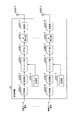
- FIG. 9 is a schematic block diagram showing a configuration of a transmission device a3 according to the third embodiment of the present invention.
- the pilot generation unit a301-t generates a pilot signal in which the receiving device b3 stores in advance the amplitude value of the waveform (or the signal sequence), and outputs the pilot signal to the mapping unit a304-t.
- the encoding unit a302-t encodes information bits to be transmitted to the receiving apparatus b3 using an error correction code such as a convolutional code, a turbo code, and an LDPC code, and generates encoded bits.
- the encoding unit a302-t outputs the generated encoded bits to the modulating unit a303-t.
- the modulation unit a303-t modulates the coded bits input from the coding unit a302-t using a modulation scheme such as PSK or QAM, and generates a modulation symbol.
- the modulation unit a303-t outputs the generated modulation symbol to the mapping unit a304-t.
- the mapping unit a304-t maps the pilot signal input from the pilot generation unit a301-t and the modulation symbol input from the modulation unit a303-t to resources based on predetermined mapping information. And the generated frequency domain signal is output to the IFFT unit a305-t. Also, the mapping information is determined by the transmission device a3 and is notified in advance from the transmission device a3 to the reception device b3.
- the IFFT unit a305-t performs frequency-time conversion on the frequency domain signal input from the mapping unit a304-t to generate a time domain signal.
- the IFFT unit a305-t outputs the generated time domain signal to the GI insertion unit a306-t.
- the GI insertion unit a306-t adds a guard interval for each signal in the FFT interval to the time domain signal input from the IFFT unit a305-t.
- the guard interval is a known signal or the like using a cyclic prefix, a zero padding followed by a zero interval, a Golay code, or the like, which is a part of the rear of the signal in the FFT interval, and the GI insertion unit a306. -T adds such a signal in front of the signal in this FFT interval.
- the GI insertion unit a306-t outputs a signal with the guard interval added to the transmission unit a307-t.
- a guard interval may be inserted behind the FFT interval.
- the transmission unit a307-t performs digital / analog conversion on the signal input from the GI insertion unit a306-t, and shapes the converted analog signal.
- the transmission unit a307-t upconverts the waveform-shaped signal from the baseband to the radio frequency band, and transmits the signal from the transmission antenna a308-t to the reception device b3.
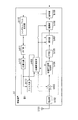
- FIG. 10 is a schematic block diagram showing the configuration of the receiving device b3 according to this embodiment.
- subtracting sections b303-1 to b303-R, extended FFT section extracting sections b304-1 to b304-R, FFT sections b305-1 to b305-R, restoring sections b307-1 to b307-R, received signal replica generating sections B3-1 to B3-R (filter units b313-1 to b313-R described later) are referred to as signal extraction unit B3.
- the reception unit b302-r receives the transmission signal transmitted from the transmission device a3 via the reception antenna b301-r.
- the receiving unit b302-r performs frequency conversion and analog-digital conversion on the received signal.
- the receiving unit b302-r stores the converted received signal.
- the reception unit b302-r generates a reception signal to be stored and generates a subtraction unit b303-r and a reception signal replica at the timing of initial processing and when a summation unit b314-r described later inputs the reception signal replica to the subtraction unit b303-r. Output to part B3-r.
- the subtraction unit b303-r subtracts the reception signal replica input from the reception signal replica generation unit B3-r described later from the reception signal input from the reception unit b302-r.
- the subtractor b303-r outputs a signal obtained by subtracting the received signal replica to the extended FFT section extractor b304-r.
- the subtraction unit b303-r receives the reception signal input from the reception unit b302-r. Is directly output to the extended FFT section extraction unit b304-r.
- the extended FFT section extraction unit b304-r outputs a signal in a signal processing section that reduces the amount of interference to the FFT unit b305-r based on the channel impulse response input from the propagation path estimation unit b306 described later. Further, the information indicating the extracted signal processing section is output to the propagation path estimation unit b306. Details of this processing will be described later together with the operation principle.
- the FFT unit b305-r performs time-frequency conversion on the time-domain signal input from the extended FFT interval extraction unit b304-r, and outputs the converted frequency-domain signal to the restoration unit b307-r.
- the reception signal replica generation unit B3-r estimates the frequency response from each of the antennas a308-t (referred to as the t-th antenna) of the transmission device a3 to the antenna b301-r (referred to as the r-th antenna), It outputs to the demodulation part b308.
- the reception signal replica generation unit B3-r calculates noise power, ISI, and ICI power, and outputs them to the demodulation unit b309.
- the reception signal replica generation unit B3-r generates a reception signal replica of the reception signal received by the r-th antenna from the symbol replica input from the symbol replica generation unit b310-t and outputs the reception signal replica to the subtraction unit b303-r. To do. Details of the configuration and processing of the reception signal replica generation unit B3-r will be described later.
- the restoration unit b307-r For each subcarrier, the restoration unit b307-r multiplies the frequency response input from the propagation path estimation unit b306 by a symbol replica input from a symbol replica generation unit b310-t, which will be described later, to thereby influence the propagation path. A replica signal of the received desired signal is generated.
- the restoration unit b307-r adds the generated replica signal to the signal input from the FFT unit b305-r for each subcarrier. That is, the restoration unit b307-r generates a replica signal of the desired signal based on the propagation path estimation value and the symbol replica, and the replica signal of the desired signal with respect to the frequency domain signal converted by the FFT unit b305-r. Are added to extract each subcarrier component of the received signal.
- the restoration unit b307-r outputs a signal obtained by adding the replica signal to the demodulation unit b308.
- the restoration unit b307-r receives the signal input from the FFT unit b305-r.
- the data is output to the demodulator b308 as it is.
- the demodulation unit b308 calculates filter coefficients using the ZF standard, the MMSE standard, and the like using the frequency response, noise power, and interference power input from the propagation path estimation unit b306.
- the demodulator b308 performs propagation path compensation using the calculated filter coefficient.
- the demodulator b308 demaps the signal subjected to propagation path compensation based on the mapping information notified in advance from the transmission device a1, and performs demodulation processing on the demapped signal.
- the demodulation unit b308 outputs a bit log likelihood ratio as a result of the demodulation process to the decoding unit b309-t for the signal of the transmission signal sequence (referred to as the tth stream) transmitted from the tth antenna.
- the decoding unit b309-t uses the maximum likelihood decoding method, maximum a posteriori probability estimation, log-MAP, Max-log-MAP, SOVA, or the like for the demodulated symbol input from the demodulation unit b308, for example. I do.
- the decoding unit b309-t determines the bit log likelihood ratio of the decoding result as the information data bit. Output as.
- the decoding unit b309-t sends the bit log likelihood ratio of the decoding result to the symbol replica generation unit b310-t. Output.
- the symbol replica generation unit b310-t calculates an expected value of the bit log likelihood ratio input from the decoding unit b309-t and modulates the calculated expected value to generate a symbol replica.
- the symbol replica generation unit b310-t maps the generated symbol replica based on mapping information notified in advance from the transmission device a3.
- the symbol replica generation unit b310-t outputs the mapped symbol replicas to the restoration units b307-1 to b307-R and the reception signal replica generation units B3-1 to B3-R.
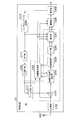
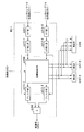
- FIG. 11 is a schematic block diagram showing a configuration of the reception signal replica generation unit B3-r according to the present embodiment.
- the received signal replica generation unit B3-r includes an IFFT unit b311-t, a GI insertion unit b312-t, a propagation path estimation unit b306, a filter unit b313-t, and a summation unit b314. .
- the IFFT unit b311-t performs frequency time conversion on the symbol replica input from the symbol replica generation unit b310-t, and outputs the converted time domain replica signal to the GI insertion unit b312-t.
- the GI insertion unit b312-t adds a guard interval for each signal in the FFT interval to the replica signal input from the IFFT unit b311-t to generate a transmission signal replica.
- the GI insertion unit b312-t outputs the generated transmission signal replica to the propagation path estimation unit b306 and the filter unit b313-t.
- the propagation path estimating unit b306 Based on the received signal input from the receiving unit b302-r and the transmission signal replica signal input from the GI inserting unit b312-t, the propagation path estimating unit b306 receives the signal from each of the t-th antennas in the OFDM symbol period. Estimate the channel impulse response of the propagation path to the r antenna. In the case of the first processing, there is no input from the GI insertion unit b312-t to the propagation path estimation unit b306 (zero), and the propagation path estimation unit b306 receives the pilot signal stored in advance and the reception unit b302-r. Based on the received signal input from, a channel impulse response that varies with time in the OFDM symbol period is estimated.
- the propagation path estimation unit b306 outputs the estimated channel impulse response to the filter unit b313-t and the extended FFT section extraction unit b304-t. Further, the propagation path estimation unit b306 performs time-frequency conversion corresponding to the signal processing interval indicated by the information input from the extended FFT interval extraction unit b304-r on the estimated channel impulse response, and estimates the frequency response. . The propagation path estimation unit b306 outputs the estimated frequency response to the restoration unit b307-r and the demodulation unit b308. Moreover, the propagation path estimation part b306 measures noise power and interference power in a pilot subcarrier using the pilot signal memorize
- the filter unit b313-t Based on the channel impulse response input from the propagation path estimation unit b306 and the transmission signal replica input from the GI insertion unit b312-t, the filter unit b313-t transmits the t-th stream received by the r-th antenna. A received signal replica is generated. The filter unit b313-t outputs the generated received signal replica to the total unit b314. The summation unit b314 sums the reception signal replicas input from the filter unit b313-t, and generates a reception signal replica of the reception signal received by the r-th antenna. The summation unit b314 outputs the generated received signal replica to the subtraction unit b303-r.
- the received signals r i, k, r of the i-th symbol at the k-th discrete time received by the receiving unit b302-r are expressed by the following equations (34), (35).
- T is the number of antennas of the transmission device a3
- D is the maximum propagation path number
- hi , d, k, r, and t are the i-th symbol in the d-th path from the t-th antenna to the r-th antenna.
- k is the complex amplitude at discrete time.
- s i, k, t is the time domain transmission signal of the i th symbol of the t th stream
- z i, k, r is the noise of the i th symbol in the r th antenna.
- N is the number of points in the FFT interval
- S i, n, t is the modulation signal of the n-th subcarrier of the i-th symbol of the t-th stream
- N g is the number of points in the GI interval
- j is an imaginary unit.
- the subtracting unit b303-r subtracts the received signal replica from the received signal r i, k, r expressed by Expression (34).
- the extended FFT interval extraction unit b304-r extracts the FFT interval of the preceding wave, and the FFT unit b305-r outputs the output of the extended FFT interval extraction unit b304-r To time-frequency conversion.
- Signals R ′ i, n, r output from the FFT unit b305-r are expressed by the following equations (36) and (37).
- S ′′ i, m, t is a symbol replica of the signal of the m-th subcarrier of the t-th stream.
- the restoration unit b307-r multiplies the symbol replica S ′′ i, n, t by the frequency response W i, n, n, r, t input from the propagation path estimation unit b306, and is affected by the propagation path. Then, a replica signal W i, n, n, r, t S ′′ i, n, t of a desired signal is generated for the n-th subcarrier of the i-th symbol of the t-th stream received by the r-th antenna.
- the restoration unit b307-r adds the generated replica signals W i, n, n, r, t S ′′ i, n, t to the signal R ′ i, n, r represented by Expression (36). That is, the restoration unit b307-r extracts the subcarrier component of the frequency domain signal transformed by the FFT unit b305-r, and the subcarrier component of the replica signal of the desired signal is extracted from the extracted subcarrier component signal. The desired stream component is added.
- the signal Y i, n, r, t after the addition is expressed by the following equation (38).
- the equation (38) means that the MIMO separation is performed.
- the demodulator b308 calculates the demodulated symbols S ′ i, n, t of the n-th subcarrier of the t-th stream using the following equation (39).
- the following equation (39) is an equation when the removal residual is approximated with noise.
- V i, n, m, r, t, 1 are ISI coefficients from the previous symbol of the t-th stream received by the r-th antenna
- V i, n, m, r, t, 2 is the ISI coefficient after the next one.
- the restoration unit b307-r multiplies the symbol replica S ′′ i, n, t by the frequency response W i, n, n, r, t to obtain a replica signal W i, n, n, r, t S i, n, t are generated.
- the restoration unit b307-r adds the generated replica signals W i, n, n, r, t S ′′ i, n, t to the signal R ′ i, n, r represented by the equation (40).
- the signal Y i, n, r, t after the addition is expressed by the following equation (42).
- the demodulator b308 calculates the demodulated symbols S ′ i, n, t of the n-th subcarrier of the t-th stream using the following equation (43).
- the following equation (43) is an equation when the removal residual is approximated with noise.
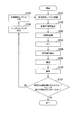
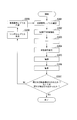
- FIG. 12 is a flowchart showing the operation of the receiving device b3 according to this embodiment. The operation shown in this figure is processing after the reception unit b302-r in FIG. 11 outputs the reception signal to the subtraction unit b303-r for the first time.
- Step S301 The subtraction unit b303-r subtracts the reception signal replica input from step S308 described later from the reception signal. Thereafter, the process proceeds to step S302.
- Step S302 The extended FFT section extraction unit b305-r extracts an FFT section in which interference is reduced from the signal resulting from the subtraction in Step S301. Thereafter, the process proceeds to step S303.
- Step S303 The FFT unit b305-r performs time-frequency conversion on the signal in the FFT interval extracted in Step S302. Thereafter, the process proceeds to step S304.
- Step S304 For each subcarrier, the restoration unit b307 performs the FFT interval extracted by the extended FFT interval extraction unit b304-r on the symbol replica generated in step S308, which will be described later, with respect to the signal resulting from the conversion in step S303. The replica signal multiplied by the frequency response of the signal is added. Thereafter, the process proceeds to step S305.
- Step S305 The demodulator b308-r performs propagation path compensation on the signal resulting from the addition in Step S304, and calculates a bit log likelihood ratio. Thereafter, the process proceeds to step S306.
- Step S306 The decoding unit b309-t performs decoding processing such as error correction on the bit log likelihood ratio of the calculation result in step S305. Thereafter, the process proceeds to step S307.
- Step S307 The decoding unit b309-t determines whether no error is detected in the decoding result in step S306, or whether a predetermined number of processes have been performed. When it corresponds to either of these (Yes), receiving device b3 ends processing. On the other hand, when it does not correspond to both of these (No), it progresses to step S308.
- Step S308 The symbol replica generation unit b310-t generates a symbol replica from the bit log likelihood ratio of the decoding result in step S305. Thereafter, the process proceeds to step S309.
- Step S309 The reception signal replica generation unit B3-r generates a reception signal replica based on the symbol replica generated in step S308. Then, it progresses to step S301.
- the receiving apparatus b3 extracts each subcarrier component of the received signal from which ISI and ICI have been removed, and demodulates the extracted signal of each subcarrier component. Thereby, the receiving apparatus b3 can prevent an increase in the amount of calculation even in the case of the MIMO transmission method.
- the receiving device b3 does not restore the signals of other streams even if it is a desired subcarrier, but may restore it. That is, you may restore
- the demodulator performs MIMO separation, and not only linear processing such as ZF and MMSE, but also maximum likelihood detection (MLD; Maximum Likelihood Detection; hereinafter, the abbreviation MLD means maximum likelihood detection. It is also possible to perform nonlinear processing such as
- the restoration unit b307 adds the generated replica signals W i, n, n, r, t S ′′ i, m, t to the signal R ′ i, n, r represented by the equation (40) for all t. . That is, the restoration unit b307-r extracts the subcarrier component of the frequency domain signal transformed by the FFT unit b305-r, and the subcarrier component of the replica signal of the desired signal is extracted from the extracted subcarrier component signal. All stream components are added.
- the signal Y n, r, t after this addition is expressed by the following equations (56) and (57).
- Expression (56) when expressed as a vector, it is expressed by the following Expressions (58) to (61).
- T represents transposing the matrix.
- M is a modulation multi-level number.
- M 2 in QPSK
- M 4 in 16QAM.
- B i, n, t, q represents the qth bit of the t-th stream constituting the vector S i, n .
- the i-th symbol and the n-th subcarrier are represented, and the subscripts i and n are omitted. That is, ⁇ i, n is expressed as ⁇ , b i, n, t, q as b t, q .
- the bit log likelihood ratio ⁇ (b t, q ) of the bits b t, q in the equation (62) is expressed by the following equation (63).
- Equation (63) the bit log likelihood ratio ⁇ (b t, q ) of Equation (63) is Is expressed by the following equation (64).
- bit log likelihood ratio ⁇ (b t ′, q ′ ) can be calculated using the bit log likelihood ratio ⁇ a (b t ′, q ′ ) output from the decoding unit b309-t ′. Further, since the bit log likelihood ratio ⁇ (b t, q ) obtained in this way is calculated using the bit log likelihood ratio ⁇ a (b t, q ), the corresponding amount is subtracted. It is common. That is, the value output from the demodulation unit b308 to the decoding unit b309-t is ⁇ (b t, q ) ⁇ a (b t, q ). For simplicity, the LLR may be calculated on the assumption that there is no prior information. In this case, the bit log likelihood ratio ⁇ (b t, q ) is expressed by the following equation (67).
- the demodulator b308 calculates the bit log likelihood ratio ⁇ (b t, q ) as a result of the demodulation process using the equation (67), and outputs it to the decoder b309-t.
- the MLD for calculating all candidates has been described.
- the present invention is also applicable to a computational complexity reduction type MLD such as an MLD using QRM-MLD or sphere decoding. it can.
- the section extracted by the extended FFT section extraction unit b304-r is from the leading end of the preceding wave to the end of the maximum delay path, but is not limited thereto. For example, it may be possible to extract from the front end to the end of the path with the highest power. Also in the third embodiment, the window function may be multiplied as in the second embodiment.
- the transmission device a3 (FIG. 9) includes one encoding unit a302-t for one antenna a308-t.
- one encoding unit may be provided for a plurality of antennas.
- the transmission device a3 may include one encoding unit, and distribute and output the result of error correction encoding to the modulation units a303-1 to a303-T according to a predetermined pattern.
- the first to Tth streams may include transmission signals of the same information data signal sequence, or may be transmission signals of different information data signal sequences.
- the transmission device a3 may transmit one information data sequence as the first and second streams and transmit the other information data signal sequence as the third and fourth streams. Good.
- the receiving devices b1, b2, and b3 subtract the received signal replica from the received signal in the time domain.
- the present invention is not limited to this, and the received signal replica may be subtracted from the received signal in the frequency domain.
- the receiving unit b102 outputs the received signal to the extended FFT section extracting unit b104
- the filter unit b113 outputs the received signal replica to the extended FFT section extracting unit b104.
- the extended FFT section extraction unit b104 extracts the signal of the FFT section indicated by the extraction section information from the reception signal input from the reception unit b102 and the reception signal replica input from the filter unit b113, after multiplying by a window.
- the FFT unit b105 performs time frequency conversion on the signal extracted by the extended FFT section extraction unit b104.
- the restoration unit b107 subtracts the received signal replica from the received signal in the FFT interval in which the FFT unit b105 performs the time frequency conversion.
- the restoration unit b107 adds the replica signal by using the subtracted signal as the signal R ′ i, n in Expression (13) or (23).
- transmission devices a1 and a3 and the reception devices b1 to b3 in the above-described embodiment for example, pilot generation units a101 and a301-t, coding units a102 and a302-t, modulation units a103 and a303-t, mapping Unit a104, a304-t, IFFT unit a105, a305-t, GI insertion unit a106, a306-t, transmission unit a107, a307-t, reception unit b102, b302-r, subtraction unit b103, b303-r, extended FFT Section extraction units b104, b204, b304-r, FFT units b105, b205, b305-r, propagation path estimation units b106, b206, b306, restoration units b107, b207, b307-r, demodulation units b108, b208, b308, decoding Parts b109, b309-
- a program for realizing this control function may be recorded on a computer-readable recording medium, and the program recorded on this recording medium may be read into a computer system and executed.
- the “computer system” is a computer system built in the transmission devices a1 and a3 or the reception devices b1 to b3, and includes hardware such as an OS and peripheral devices.
- the “computer-readable recording medium” refers to a storage device such as a flexible medium, a magneto-optical disk, a portable medium such as a ROM or a CD-ROM, and a hard disk incorporated in a computer system.
- the “computer-readable recording medium” is a medium that dynamically holds a program for a short time, such as a communication line when transmitting a program via a network such as the Internet or a communication line such as a telephone line,
- a volatile memory inside a computer system serving as a server or a client may be included and a program that holds a program for a certain time.
- the program may be a program for realizing a part of the functions described above, and may be a program capable of realizing the functions described above in combination with a program already recorded in a computer system.
- the transmission devices a1 and a3 and the reception devices b1 to b3 in the above-described embodiments may be realized as an integrated circuit such as an LSI (Large Scale Integration).
- LSI Large Scale Integration
- Each functional block of the transmission devices a1 and a3 and the reception devices b1 to b3 may be individually made into a processor, or a part or all of them may be integrated into a processor.
- the method of circuit integration is not limited to LSI, and may be realized by a dedicated circuit or a general-purpose processor. Further, in the case where an integrated circuit technology that replaces LSI appears due to progress in semiconductor technology, an integrated circuit based on the technology may be used.
- the present invention is suitable for use in a communication device such as a receiving device.
- a1, a3... transmitting device b1, b2, b3... receiving device, a101, a301-t... pilot generating unit, a102, a302-t .. coding unit, a103, a303-t.
- Modulation unit a104, a304-t ... mapping unit, a105, a305-t ... IFFT unit, a106, a306-t ... GI insertion unit, a107, a307-t ... transmission unit, a108 , A308-t ... transmitting antenna part, b101, b301-r ... receiving antenna, b102, b302-r ... receiving part, b103, b303-r ...
Abstract
伝搬路推定部は、伝搬路推定値を推定する。シンボルレプリカ生成部は、復調した情報の変調シンボルであるシンボルレプリカを生成する。信号抽出部は、伝搬路推定値とシンボルレプリカとに基づいて、干渉を除去した受信信号の各サブキャリア成分を任意の長さの時間区間で抽出する。復調部は、信号抽出部が抽出した時間区間の信号に基づいて、前記受信信号の各サブキャリア成分の信号を復調する。
Description
本発明は、受信装置、受信方法、受信プログラム、及びプロセッサに関する。
本願は、2010年03月08日に、日本に出願された特願2010-050849号に基づき優先権を主張し、その内容をここに援用する。
本願は、2010年03月08日に、日本に出願された特願2010-050849号に基づき優先権を主張し、その内容をここに援用する。
無線通信においては、特に広帯域伝送の場合、先行して受信するパスに加え、建物や山などの障害物からの反射を経由する等して遅延して到来するパスが存在し、シンボル間干渉(ISI:Inter Symbol Interference)となる。このように複数のパスが到来する環境をマルチパス環境という。例えば、OFDM(Orthogonal Frequency Division Multiplexing;直交周波数分割多重)、OFDMA(Orthogonal Frequency Division Multiple Access;直交周波数多元接続)、MC-CDM(Multi Carrier-Code Division Multiplexing;マルチキャリア-符号分割多重)などのマルチキャリア伝送では、マルチキャリアの時間領域の信号にガードインターバル(GI:Guard Interval)を付加することで、GI以内の遅延パスであればISIが生じることを防止する。しかしながら、GIを超える遅延パスが存在する場合、ISIに加え、FFT(高速フーリエ変換:Fast Fourier Transform)の周期性が崩れるためにキャリア間干渉(ICI:Inter Carrier Interference)も生じる。ISIやICIは受信性能を大幅に劣化させる。
非特許文献1には、ターボ等化を用いてISIやICIを低減する技術が記載されている。具体的に、非特許文献1には、誤り訂正復号結果のビット対数尤度比(LLR:Log Likelihood Ratio)から送信信号のレプリカを作成し、それを用いて受信信号を構成するマルチパスを複数のブロックに分割し、周波数領域で所望信号のみを処理することでISIおよびICIを抑圧することで、良好な受信品質を実現するものである。
K. Kato, R. Yamada, T. Yoshimoto, K. Shimezawa, M. Kubota, and N. Okamoto、「Multipath Division Turbo Equalization with Block Inter-Carrier Interference Cancellation in Cellular System with Amplify-and-Forward Relaying」in Proc. IEEE PIMRC 2009、2009年9月
しかしながら非特許文献1は、複数のブロックを周波数領域に変換するため、FFTの回数が多く、計算量が増大するという問題があった。
本発明は上記の点に鑑みてなされたものであり、計算量並びに回路規模の増大を抑えながら、良好な受信特性を得ることができる受信装置、受信方法、受信プログラム、及びプロセッサを提供する。
(1)本発明は上記の課題を解決するためになされたものであり、本発明の一態様は、受信信号及び少なくとも1回の受信処理によって得られるビット対数尤度比から得られる時間領域での受信信号のレプリカである受信信号レプリカを用いて、任意の時間区間の信号を抽出し、抽出した信号を時間周波数変換して少なくともキャリア間干渉が抑圧された受信信号の各サブキャリア信号を求める信号抽出部を備えることを特徴とする受信装置である。
(2)また、本発明の一態様は、上記の受信装置において、伝搬路推定を行って伝搬路推定値を求める伝搬路推定部と、前記ビット対数尤度比から変調シンボルのレプリカであるシンボルレプリカを生成するシンボルレプリカ生成部と、を備え、前記信号抽出部は、前記伝搬路推定値と前記シンボルレプリカとに基づいて、前記受信信号レプリカを生成するフィルタ部と、前記受信信号から前記受信信号レプリカを減算する減算部と、前記減算部が減算した信号から任意の長さの時間区間の信号である拡張FFT区間信号を抽出し、該拡張FFT区間信号からFFT信号を生成する拡張FFT区間抽出部と、前記FFT信号を、周波数領域の信号に変換する時間周波数変換部と、前記伝搬路推定値と前記シンボルレプリカとに基づいてサブキャリアレプリカ信号を生成し、前記時間周波数変換部が変換した周波数領域の信号に対して前記サブキャリアレプリカ信号を加算し、前記受信信号の各サブキャリア信号を求める復元部と、を備えることを特徴とする。
(3)また、本発明の一態様は、上記の受信装置において、伝搬路推定を行って伝搬路推定値を求める伝搬路推定部と、前記ビット対数尤度比から変調シンボルのレプリカであるシンボルレプリカを生成するシンボルレプリカ生成部と、を備え、前記信号抽出部は、前記伝搬路推定値と前記シンボルレプリカとに基づいて、前記受信信号レプリカを生成するフィルタ部と、任意の時間区間の信号である拡張FFT区間信号を抽出し、該拡張FFT区間信号からFFT区間信号を生成する拡張FFT区間抽出部と、前記受信信号から生成された第1のFFT区間信号と前記受信信号レプリカから生成された第2のFFT区間信号を周波数領域の信号に変換する時間周波数変換部と、前記周波数領域の第1のFFT区間信号から前記周波数領域の第2のFFT区間信号を減算する減算部と、前記伝搬路推定値と前記シンボルレプリカとに基づいてサブキャリアレプリカ信号を生成し、前記減算部が減算した信号に対して前記サブキャリアレプリカ信号を加算し、任意の時間区間での受信信号の各サブキャリア成分を抽出する復元部と、を備えることを特徴とする。
(4)また、本発明の一態様は、上記の受信装置において、前記フィルタ部は、周波数時間変換をしたシンボルレプリカと前記伝搬路推定値に基づいて、前記受信信号レプリカを生成することを特徴とする。
(5)また、本発明の一態様は、上記の受信装置において、前記拡張FFT区間信号の区間長は、前記FFT区間信号よりも長いことを特徴とする。
(6)また、本発明の一態様は、上記の受信装置において、前記FFT区間信号には、前記拡張FFT区間信号のうち前記FFT区間信号の区間長以上の信号が含まれていることを特徴とする。
(7)また、本発明の一態様は、上記の受信装置において、前記拡張FFT区間信号の時間区間の開始位置が前記FFT区間信号の時間区間の開始位置と異なることを特徴とする。
(8)また、本発明の一態様は、上記の受信装置において、前記拡張FFT区間信号の時間区間の開始位置が前記FFT区間信号の時間区間の開始位置と同じであることを特徴とする。
(9)また、本発明の一態様は、上記の受信装置において、前記拡張FFT区間信号は、信号を抽出する時間区間の始まりを先行パスの先端とし、前記時間区間の終わりを最大遅延パスの信号の後端とすることを特徴とする。
(10)また、本発明の一態様は、上記の受信装置において、前記拡張FFT区間抽出部は、抽出した信号区間に窓関数を乗算することを特徴とする。
(11)また、本発明の一態様は、上記の受信装置において、前記復元部は、前記時間周波数変換部が変換した周波数領域の信号のサブキャリア成分を抽出し、抽出したサブキャリア成分の信号に対して、前記所望信号のレプリカ信号の当該サブキャリア成分を加算することを特徴とする。
(12)また、本発明の一態様は、上記の受信装置において、前記復元部は、前記時間周波数変換部が変換した周波数領域の信号のサブキャリア成分を抽出し、抽出したサブキャリア成分の信号に対して、前記所望信号のレプリカ信号のサブキャリア成分であって当該サブキャリアに近接するサブキャリアの成分を加算することを特徴とする。
(13)また、本発明の一態様は、上記の受信装置において、前記受信装置は、複数のアンテナを備え、前記受信装置は、送信装置とMIMO伝送方式の通信を行うことを特徴とする。
(14)また、本発明の一態様は、上記の受信装置において、前記復調部は、前記伝搬路推定値に基づいてMIMO分離を行うことを特徴とする。
(15)また、本発明の一態様は、上記の受信装置において、前記受信装置は、送信装置が備える複数のアンテナ各々から送信された信号系列であるストリームの信号を、前記受信信号として受信し、前記信号抽出部は、前記伝搬路推定値と前記シンボルレプリカとに基づいて、時間領域での受信信号のレプリカである受信信号レプリカを生成するフィルタ部と、前記受信信号から前記受信信号レプリカを減算する減算部と、前記減算部が減算した信号から任意の長さの時間区間の信号を抽出する拡張FFT区間抽出部と、前記拡張FFT区間抽出部が抽出した時間区間の信号を、周波数領域の信号に変換する時間周波数変換部と、前記伝搬路推定値と前記シンボルレプリカとに基づいて所望信号のレプリカ信号を生成し、前記時間周波数変換部が変換した周波数領域の信号に対して前記所望信号のレプリカ信号を加算し、任意の長さの時間区間での受信信号の各サブキャリア成分を抽出する復元部と、を備え、前記復元部は、前記時間周波数変換部が変換した周波数領域の信号のサブキャリア成分を抽出し、抽出したサブキャリア成分の信号に対して、前記所望信号のレプリカ信号の当該サブキャリア成分のうち所望のストリーム成分を加算することを特徴とする。
(16)また、本発明の一態様は、上記の受信装置において、前記受信装置は、送信装置が備える複数のアンテナ各々から送信された信号系列であるストリームの信号を、前記受信信号として受信し、前記信号抽出部は、前記伝搬路推定値と前記シンボルレプリカとに基づいて、時間領域での受信信号のレプリカである受信信号レプリカを生成するフィルタ部と、前記受信信号から前記受信信号レプリカを減算する減算部と、前記減算部が減算した信号から任意の長さの時間区間の信号を抽出する拡張FFT区間抽出部と、前記拡張FFT区間抽出部が抽出した時間区間の信号を、周波数領域の信号に変換する時間周波数変換部と、前記伝搬路推定値と前記シンボルレプリカとに基づいて所望信号のレプリカ信号を生成し、前記時間周波数変換部が変換した周波数領域の信号に対して前記所望信号のレプリカ信号を加算し、任意の長さの時間区間での受信信号の各サブキャリア成分を抽出する復元部と、を備え、前記復元部は、前記時間周波数変換部が変換した周波数領域の信号のサブキャリア成分を抽出し、抽出したサブキャリア成分の信号に対して、前記所望信号のレプリカ信号の当該サブキャリア成分のうち全てのストリーム成分を加算することを特徴とする。
(17)また、本発明の一態様は、上記の受信装置において、前記復調部は、最小平均2乗誤差基準で信号を復調することを特徴とする。
(18)また、本発明の一態様は、信号抽出部が、受信信号及び少なくとも1回の受信処理によって得られるビット対数尤度比から得られる時間領域での受信信号のレプリカである受信信号レプリカを用いて、任意の時間区間の信号を抽出し、抽出した信号を時間周波数変換して少なくともキャリア間干渉が抑圧された受信信号の各サブキャリア信号を求める信号抽出過程を有することを特徴とする受信方法である。
(19)また、本発明の一態様は、受信装置のコンピュータを、受信信号及び少なくとも1回の受信処理によって得られるビット対数尤度比から得られる時間領域での受信信号のレプリカである受信信号レプリカを用いて、任意の時間区間の信号を抽出し、抽出した信号を時間周波数変換して少なくともキャリア間干渉が抑圧された受信信号の各サブキャリア信号を求める信号抽出手段として機能させる受信プログラムである。
(20)また、本発明の一態様は、受信信号及び少なくとも1回の受信処理によって得られるビット対数尤度比から得られる時間領域での受信信号のレプリカである受信信号レプリカを用いて、任意の時間区間の信号を抽出し、抽出した信号を時間周波数変換して少なくともキャリア間干渉が抑圧された受信信号の各サブキャリア信号を求めるプロセッサである。
(21)また、本発明の一態様は、ガードインターバルが付加された送信信号を受信して、該受信した受信信号から変調シンボルを復調する受信装置における受信方法において、FFT区間を通常より長く、または、通常と異なる位置に設定される、拡張FFT区間を用いてFFT区間信号を求める過程を有することを特徴とする受信方法である。
本発明によれば、計算量並びに回路規模の増大を抑えながら、良好な受信特性を得ることができる。
(第1の実施形態)
以下、図面を参照しながら本発明の実施形態について詳しく説明する。本実施形態では、送信装置a1と受信装置b1とが通信を行う。
以下、図面を参照しながら本発明の実施形態について詳しく説明する。本実施形態では、送信装置a1と受信装置b1とが通信を行う。
<送信装置a1の構成について>
図1は、本発明の第1の実施形態に係る送信装置a1の概略ブロック図である。この図において、送信装置a1は、パイロット生成部a101、符号部a102、変調部a103、マッピング部a104、IFFT部a105、GI挿入部a106、送信部a107、及び送信アンテナ部a108を含んで構成される。
図1は、本発明の第1の実施形態に係る送信装置a1の概略ブロック図である。この図において、送信装置a1は、パイロット生成部a101、符号部a102、変調部a103、マッピング部a104、IFFT部a105、GI挿入部a106、送信部a107、及び送信アンテナ部a108を含んで構成される。
パイロット生成部a101は、受信装置がその波形(あるいは、その信号系列)の振幅値を予め記憶するパイロット信号を生成し、マッピング部a104に出力する。なお、以下、本実施形態では、受信装置をb1という。
符号部a102は、受信装置b1に送信する情報ビットに対して畳込み符号、ターボ符号、LDPC(Low Density Parity Check:低密度パリティ検査)符号などの誤り訂正符号を用いて符号化し、符号化ビットを生成する。符号部a102は、生成した符号化ビットを変調部a103に出力する。
変調部a103は、符号部a102から入力された符号化ビットを、PSK(Phase Shift Keying:位相偏移変調)やQAM(Quadrature amplitude modulation:直交振幅変調)などの変調方式を用いて変調し、変調シンボルを生成する。変調部a103は、生成した変調シンボルをマッピング部a104に出力する。
マッピング部a104は、パイロット生成部a101から入力されたパイロット信号、及び変調部a103から入力された変調シンボルを、予め定められたマッピング情報に基づいてリソース(時間-周波数帯域)にマッピングして周波数領域の信号を生成し、生成した周波数領域の信号をIFFT部a105に出力する。なお、リソースとは、送信装置a1が送信するフレームにおいて1つのサブキャリアと1つの後述するFFT区間から成る、変調シンボルを配置する単位である。また、マッピング情報は、送信装置a1が決定し、送信装置a1から受信装置b1へ予め通知される。
IFFT部a105は、マッピング部a104から入力された周波数領域の信号を周波数-時間変換し、時間領域の信号を生成する。ここで、IFFTを行う単位の時間区間をFFT区間という。IFFT部a105は、生成した時間領域の信号をGI挿入部a106に出力する。
IFFT部a105は、マッピング部a104から入力された周波数領域の信号を周波数-時間変換し、時間領域の信号を生成する。ここで、IFFTを行う単位の時間区間をFFT区間という。IFFT部a105は、生成した時間領域の信号をGI挿入部a106に出力する。
GI挿入部a106は、IFFT部a105から入力された時間領域の信号に対して、FFT区間の信号毎にガードインターバルを付加する。ここで、ガードインターバルとは、FFT区間の信号の後方の一部を複製したものであるサイクリックプレフィックス(Cyclic Prefix:CP)やゼロ区間が続くゼロパディング、Golay符号等を用いた既知信号等であり、GI挿入部a106は、このような信号をこのFFT区間の信号の前方に付加する。
なお、FFT区間と、GI挿入部a106がその時間区間の信号に付加したガードインターバルの時間区間(GI区間という)と、を併せてOFDMシンボル区間という。また、OFDMシンボル区間の信号をOFDMシンボルという。GI挿入部a106は、ガードインターバルを付加した信号を送信部a107に出力する。
なお、ガードインターバルをFFT区間の後方に挿入してもよい。例えば、サイクリックプレフィックスを用いる場合、FFT区間の前方の一部の複製を、FFT区間の信号の後方に付加する。また、サイクリックプレフィックスの場合は、OFDMシンボル区間で周期性が保たれるようにすればよく、前記の限りではない。
送信部a107は、GI挿入部a106から入力された信号をデジタル・アナログ変換し、変換したアナログ信号を波形整形する。送信部a107は、波形整形した信号をベースバンド帯から無線周波数帯にアップコンバートし、送信アンテナa108から受信装置b1へ送信する。
<受信装置b1の構成について>
図2は、本実施形態に係る受信装置b1の構成を示す概略ブロック図である。この図において、受信装置b1は、受信アンテナb101、受信部b102、減算部b103、拡張FFT区間抽出部b104、FFT部b105、伝搬路推定部b106、復元部b107、復調部b108、復号部b109、シンボルレプリカ生成部b110、IFFT部b111、GI挿入部b112、及びフィルタ部b113を含んで構成される。ここで、減算部b103、拡張FFT区間抽出部b104、FFT部b105、復元部b107、フィルタ部b113を信号抽出部B1という。
図2は、本実施形態に係る受信装置b1の構成を示す概略ブロック図である。この図において、受信装置b1は、受信アンテナb101、受信部b102、減算部b103、拡張FFT区間抽出部b104、FFT部b105、伝搬路推定部b106、復元部b107、復調部b108、復号部b109、シンボルレプリカ生成部b110、IFFT部b111、GI挿入部b112、及びフィルタ部b113を含んで構成される。ここで、減算部b103、拡張FFT区間抽出部b104、FFT部b105、復元部b107、フィルタ部b113を信号抽出部B1という。
受信部b102は、送信装置a1が送信した送信信号を、受信アンテナb101を介して受信する。受信部b102は、受信した信号に対して、周波数変換及びアナログ-デジタル変換を行う。受信部b102は、変換を行った受信信号を記憶する。受信部b102は、初回処理、及び、後述するフィルタ部b113が減算部b103に受信信号レプリカを入力するタイミングで、記憶する受信信号を減算部b103及び伝搬路推定部b106に出力する。
減算部b103は、受信部b102から入力された受信信号から、後述するフィルタ部b113から入力された受信信号レプリカを減算する。減算部b103は、受信信号レプリカを減算した信号を拡張FFT区間抽出部b104に出力する。
なお、初回処理の場合、フィルタ部b113から減算部b103への入力はなく(ゼロであり)、減算部b103は、受信部b102から入力された受信信号をそのまま拡張FFT区間抽出部b104に出力する。
なお、初回処理の場合、フィルタ部b113から減算部b103への入力はなく(ゼロであり)、減算部b103は、受信部b102から入力された受信信号をそのまま拡張FFT区間抽出部b104に出力する。
拡張FFT区間抽出部b104は、後述する伝搬路推定部b106から入力されたチャネルインパルス応答に基づいて、干渉量を少なくするような信号処理区間の信号をFFT部b105に出力する。また、抽出した信号処理区間を示す情報を伝搬路推定部b106に出力する。この処理の詳細については、動作原理と併せて後述する。
FFT部b105は、拡張FFT区間抽出部b104から入力された時間領域の信号に対して時間周波数変換を行い、変換した周波数領域の信号を復元部b107に出力する。
FFT部b105は、拡張FFT区間抽出部b104から入力された時間領域の信号に対して時間周波数変換を行い、変換した周波数領域の信号を復元部b107に出力する。
伝搬路推定部b106は、受信部b102から入力された受信信号、及び後述するGI挿入部b112から入力された送信信号レプリカ、に基づいて、OFDMシンボル区間でチャネルインパルス応答を推定する。ここで、チャネルインパルス応答の推定には、RLS(Recursive Least Square;再帰最小自乗)アルゴリズムを用いてもよいし、その他のアルゴリズム、例えばLMS(Least Mean Square;最小二乗平均)アルゴリズム等を用いてもよい。なお、初回の処理の場合、GI挿入部b112から伝搬路推定部b106への入力はなく(ゼロであり)、伝搬路推定部b106は、予め記憶するパイロット信号、及び受信部b102から入力された受信信号に基づいて、OFDMシンボル区間で時間変動するチャネルインパルス応答を推定する。
伝搬路推定部b106は、推定したチャネルインパルス応答をフィルタ部b113及び拡張FFT区間抽出部b104に出力する。また、伝搬路推定部b106は、推定したチャネルインパルス応答に対して、拡張FFT区間抽出部b104から入力された情報が示す信号処理区間に対応する時間周波数変換を行い、周波数応答を推定する。伝搬路推定部b106は、推定した周波数応答を復元部b107及び復調部b108に出力する。
また、伝搬路推定部b106は、予め記憶するパイロット信号を用い、パイロット信号が配置されるサブキャリア(パイロットサブキャリアという)において、雑音電力と干渉電力を測定する。具体的な算出方法は、動作原理と併せて後述する。
また、伝搬路推定部b106は、予め記憶するパイロット信号を用い、パイロット信号が配置されるサブキャリア(パイロットサブキャリアという)において、雑音電力と干渉電力を測定する。具体的な算出方法は、動作原理と併せて後述する。
復元部b107は、サブキャリア毎に、伝搬路推定部b106から入力された周波数応答を、後述するシンボルレプリカ生成部b110から入力されたシンボルレプリカに乗算して、伝搬路の影響を受けた所望信号のレプリカ信号を生成する。復元部b107は、サブキャリア毎に、FFT部b105から入力された信号に生成したレプリカ信号を加算する。すなわち、復元部b107は、伝搬路推定値とシンボルレプリカとに基づいて所望信号のレプリカ信号を生成し、FFT部b105が変換した周波数領域の信号に対してこの所望信号のレプリカ信号を加算し、受信信号の各サブキャリア成分を抽出する。
復元部b107は、レプリカ信号を加算した信号を復調部b108に出力する。
なお、初回の処理の場合、シンボルレプリカ生成部b110から復元部b107への入力はなく(ゼロであり)、復元部b107は、FFT部b105から入力された信号をそのまま復調部b108に出力する。
以上のように、信号抽出部B1は、伝搬路推定値とシンボルレプリカとに基づいて受信信号から受信信号レプリカを除去し、所望信号を復元することでISI及びICI(干渉)を除去した受信信号の各サブキャリア成分を抽出する。
復元部b107は、レプリカ信号を加算した信号を復調部b108に出力する。
なお、初回の処理の場合、シンボルレプリカ生成部b110から復元部b107への入力はなく(ゼロであり)、復元部b107は、FFT部b105から入力された信号をそのまま復調部b108に出力する。
以上のように、信号抽出部B1は、伝搬路推定値とシンボルレプリカとに基づいて受信信号から受信信号レプリカを除去し、所望信号を復元することでISI及びICI(干渉)を除去した受信信号の各サブキャリア成分を抽出する。
復調部b108は、伝搬路推定部b106から入力された周波数応答、雑音電力、及び干渉電力を用いて、ZF(Zero Forcing)基準、MMSE(Minimum Mean Square Error)基準等を用いたフィルタ係数を算出する。復調部b108は、算出したフィルタ係数を用いて、信号の振幅と位相の変動の補償(伝搬路補償という)を行う。復調部b108は、伝搬路補償を行った信号を、送信装置a1から予め通知されたマッピング情報に基づいてデマッピングし、デマッピングした信号に対して、復調処理を行う。復調部b108は、復調処理の結果のビット対数尤度比(LLR;Log Likelihood Ratio)を復号部b109に出力する。
復号部b109は、復調部b108から入力された復調シンボルに対して、例えば、最尤復号法(MLD; Maximum Likelihood Decoding)、最大事後確率(MAP; Maximum A posteriori Probability)、log-MAP、Max-log-MAP、SOVA(Soft Output Viterbi Algorithm)等を用いて、復号処理を行う。
この復号処理の結果、誤りが検出されなかったと判定した場合、もしくは、既定の回数の処理が行われたと判定した場合、復号部b109は、復号結果のビット対数尤度比を情報データビットとして出力する。一方、誤りが検出され、かつ、規定の回数の処理が行われていない、と判定した場合、復号部b109は、復号結果のビット対数尤度比をシンボルレプリカ生成部b110に出力する。
この復号処理の結果、誤りが検出されなかったと判定した場合、もしくは、既定の回数の処理が行われたと判定した場合、復号部b109は、復号結果のビット対数尤度比を情報データビットとして出力する。一方、誤りが検出され、かつ、規定の回数の処理が行われていない、と判定した場合、復号部b109は、復号結果のビット対数尤度比をシンボルレプリカ生成部b110に出力する。
シンボルレプリカ生成部b110は、復号部b109から入力されたビット対数尤度比の期待値を算出し、算出した期待値を変調して変調シンボル(シンボルレプリカという)を生成する。シンボルレプリカ生成部b110は、生成したシンボルレプリカを、送信装置a1から予め通知されたマッピング情報に基づいてマッピングする。シンボルレプリカ生成部b110は、マッピングしたシンボルレプリカを復元部b107及びIFFT部b111に出力する。
IFFT部b111は、シンボルレプリカ生成部b110から入力されたシンボルレプリカに対して周波数時間変換を行い、変換した時間領域のレプリカ信号をGI挿入部b112に出力する。
GI挿入部b112は、IFFT部b111から入力されたレプリカ信号に対して、FFT区間の信号毎にガードインターバルを付加して、送信信号レプリカを生成する。GI挿入部b112は、生成した送信信号レプリカを、伝搬路推定部b106及びフィルタ部b113に出力する。
フィルタ部b113は、伝搬路推定部b106から入力されたチャネルインパルス応答と、GI挿入部b112から入力された送信信号レプリカと、に基づいて、受信信号レプリカを生成する。フィルタ部b113は、生成した受信信号レプリカを減算部b103に出力する。
受信装置b1は、復号部b109が誤りを検出しなくなるまで、又は、既定の回数まで、同じ信号に対して、上記の減算部b103からフィルタ部b113までの処理を繰り返し行う(繰り返し処理という)。
図3は、本実施形態に係る受信信号の一例を示す概略図である。この図は、最大遅延がGI長を超えず、前のOFDMシンボルによる干渉は無い場合の図である。この図において、横軸は時間軸であり、予め定めた時間幅で区切られた離散時刻である。また、この図において、右斜め上がりの斜線でハッチングした領域は、ガードインターバルを示す。また、左斜め上がりの斜線でハッチングした領域は前後のOFDMシンボルの受信信号を示す。また、NはFFT(Fast Fourier Transform;高速フーリエ変換)区間のポイント数(IFFT(Inverse Fast Fourier Transform;逆高速フーリエ変換)区間のポイント数でもある)、NgはGIのポイント数である。ここで、ポイント数とは離散時刻の数である。
図3の場合、拡張FFT区間抽出部b104は、先行波のFFT区間に該当する部分(k=Ng~Ng+N-1)を信号処理区間として、その信号処理区間の信号を抽出する。拡張FFT区間抽出部b104は、抽出した信号をFFT部b105に入力する。これにより、受信装置b1は、前後のOFDMシンボルによる干渉の生じない信号を抽出できる。
図3の場合、拡張FFT区間抽出部b104は、先行波のFFT区間に該当する部分(k=Ng~Ng+N-1)を信号処理区間として、その信号処理区間の信号を抽出する。拡張FFT区間抽出部b104は、抽出した信号をFFT部b105に入力する。これにより、受信装置b1は、前後のOFDMシンボルによる干渉の生じない信号を抽出できる。
図4は、本実施形態に係る受信装置b1が選択するFFT区間の一例を示す概略図である。この図は、最大遅延がGI長を超え、前のOFDMシンボルによる干渉がある場合の図である。この図において、横軸は時間軸であり、予め定めた時間幅で区切られた離散時刻である。また、この図において、右斜め上がりの斜線でハッチングした領域は、GIを示す。
図4の場合、図3の場合のように、前後のOFDMシンボルによる干渉の生じないFFT区間はない。この場合、拡張FFT区間抽出部b104は、ポイント数をNに固定せず、干渉を小さくするような区間を選択する。例えば、拡張FFT区間抽出部b104は、図4に示す拡張FFT区間(k=0~Ng+KD+N-1)を選択する。ここで、KDは最大遅延パスの遅延時間(最大遅延時間)を示す。この図は、拡張FFT区間抽出部b104が、先行波のパスの先端から最大遅延パスの終端までを選択した場合を示す。この図において、この信号処理区間には、パス(先行波のパスを含む)は12個存在している。
図4の場合、図3の場合のように、前後のOFDMシンボルによる干渉の生じないFFT区間はない。この場合、拡張FFT区間抽出部b104は、ポイント数をNに固定せず、干渉を小さくするような区間を選択する。例えば、拡張FFT区間抽出部b104は、図4に示す拡張FFT区間(k=0~Ng+KD+N-1)を選択する。ここで、KDは最大遅延パスの遅延時間(最大遅延時間)を示す。この図は、拡張FFT区間抽出部b104が、先行波のパスの先端から最大遅延パスの終端までを選択した場合を示す。この図において、この信号処理区間には、パス(先行波のパスを含む)は12個存在している。
拡張FFT区間抽出部b104は、選択した拡張FFT区間を、k=0~N-1の前部区間とk=N~Ng+KD+N-1の後部区間との2つの区間に分割する。さらに、拡張FFT区間抽出部b104は、前部区間の一部の区間であるk=0~Ng+KDの区間と、後部区間とからなる長さNの区間を選択する。拡張FFT区間抽出部b104は、選択した区間を信号処理区間として、信号処理区間の信号を、FFT部b105に出力する。この処理については、動作原理と併せて後述する。
なお、拡張FFT区間として、通常のFFT区間より短い区間を選択してもよい。
なお、拡張FFT区間として、通常のFFT区間より短い区間を選択してもよい。
<動作原理について>
以下、受信装置b1の動作原理について、図2を参照しながら説明をする。まず、初回の処理についての動作原理について説明をする。
以下、受信装置b1の動作原理について、図2を参照しながら説明をする。まず、初回の処理についての動作原理について説明をする。
[初回処理について]
受信部b102が受信した第iシンボルの第k離散時刻の受信信号ri,kは、次式(1)、(2)で表わされる。
受信部b102が受信した第iシンボルの第k離散時刻の受信信号ri,kは、次式(1)、(2)で表わされる。

ただし、Dは最大の伝搬路番号であるが、ここでは最大遅延時間KDに等しいものとする。また、hi,d,kは第iシンボルの伝搬路番号dのパス(第dパスという)における第k離散時刻の複素振幅、si、kは第iシンボルの時間領域の送信信号であり、zi,kは第iシンボルの時間領域の雑音である。また、NはFFT区間のポイント数、Si,nは第nサブキャリアの第iシンボルの変調信号、NgはGI区間のポイント数(図4参照)、jは虚数単位である。また、0≦k≦N+Ng-1であり、k-d<0のような場合はsi,k-d=si-1,k-d+N+Ngである。
受信信号ri,kのFFT区間に対して、FFT部b105にて、時間周波数変換を行った後の信号Ri,nは、次式(3)、(4)で表わされる。
受信信号ri,kのFFT区間に対して、FFT部b105にて、時間周波数変換を行った後の信号Ri,nは、次式(3)、(4)で表わされる。

ここで、Wi,n,mは第mサブキャリアから第nサブキャリアへの信号の漏れ込み係数であり、1つのOFDMシンボル内で伝搬路の変動がなく(hi,d,k=hi,d)、かつ、最大遅延時間がガードインターバル以内(D≦Ng)の場合は、m≠nのときにWi,n,m=0となる。また、Vi,n,mは1つ前のOFDMシンボルからのISI係数であり、Zi,nは第nサブキャリアにおける雑音である。また、式(4)において、m=nである場合のWi,n,nは、第nサブキャリアの周波数応答であり、次式(5)で表わされる。

なお、式(5)は、OFDMシンボル内で時間変動しているチャネルインパルス応答の時間平均に対する離散フーリエ変換結果に一致する。初回処理において、伝搬路推定部b106は、パイロット信号を用いてWi,n,nを推定する。初回処理では、式(3)で示す信号は、FFT部b105から復元部b107を介して、そのまま復調部b108に出力される。復調部b108は、例えばMMSE基準のフィルタリングを用いた場合、復調シンボルS’i,nを、次式(6)を用いて算出する。

ここで、Y*はYの複素共役であることを示す。初回処理では、ISIおよびICIが取り除かれることなく行われる受信処理であるため、その影響を受けて伝送特性は劣化する。また、式(6)において、σz
2は雑音電力、σI
2はISIおよびICIの電力であり、次式(7)、(8)のように表わされる。


ここで、E[X]は、Xのアンサンブル平均を示す。なお、本実施形態では、伝搬路推定部b106がパイロット信号を用いてこれらの電力を算出し、その結果を式(6)に用いて復調シンボルS’i,nを算出する。具体的には、次式(9)のように計算する。

ここで、σ’2はσz
2+σI
2の推定値であり、Piは第iシンボルにおいて、パイロットサブキャリアを表わす集合である。なお、これは、充分な数の算術平均がアンサンブル平均に等しいと仮定した場合、式(9)が次式(10)のようにできることを利用した算出法である。

ここで、第1項がISIおよびICIの電力を表わし、第2項が雑音電力を表わしている。この式は、パイロット信号の電力が1に正規化され、周波数応答の電力平均が1に正規化される場合のものである。すなわち、この式は、次式(11)が満される場合のものである。

なお、パイロット信号の電力が1ではない場合は、その分の調整係数を導入すればよい。また、周波数応答の正規化は、受信部b102にてアナログ-デジタル変換されるときの振幅調整に起因する。
復調部b108は、式(6)の復調シンボルS’i,nからビット対数尤度比を算出する。この算出処理には等価振幅利得が用いられる。具体的には、QPSKの場合、次式(12)で表わされる第nサブキャリアの等価振幅利得μi,nに対して、ビット対数尤度比λは、次式(13)、(14)で表わされる。ここで、式(13)、(14)は、それぞれ、1ビット目のビットbi,n,0、2ビット目のビットbi,n,1のビット対数尤度比λ(bi,n,0)、λ(bi,n,1)である。


次に、繰返し処理の動作原理を説明する。
シンボルレプリカ生成部b110は、復号部b109が復号したビット対数尤度比の期待値を算出し、算出した期待値を変調してシンボルレプリカS’’i,nを生成する。シンボルレプリカS’’i,nは、IFFT部b111で周波数時間変換され、GI挿入部b112でGIが挿入される。GI挿入部b112が出力する送信信号レプリカs’’i,kは、次式(15)で表わされる。
シンボルレプリカ生成部b110は、復号部b109が復号したビット対数尤度比の期待値を算出し、算出した期待値を変調してシンボルレプリカS’’i,nを生成する。シンボルレプリカS’’i,nは、IFFT部b111で周波数時間変換され、GI挿入部b112でGIが挿入される。GI挿入部b112が出力する送信信号レプリカs’’i,kは、次式(15)で表わされる。

ここで、式(15)の送信信号レプリカs’’i,kを生成するために、IFFT部b111は逆高速フーリエ変換を行い、この変換での乗算回数のオーダはO(Nlog2N)である。
伝搬路推定部b106は、式(15)で表わされた送信信号レプリカ、受信部b102から入力された受信信号に基づいてチャネルインパルス応答hi,d,kを推定する。また、伝搬路推定部b106は、チャネルインパルス応答hi,d,kを時間平均してから時間周波数変換を行い、周波数応答Wi,n,nを算出する。
フィルタ部b113は、チャネルインパルス応答hi,d,kと、式(15)で表わされる送信信号レプリカs’’i,kと、に基づいて、次式(16)で表わされる受信信号レプリカをr’’i,kを生成する。
伝搬路推定部b106は、式(15)で表わされた送信信号レプリカ、受信部b102から入力された受信信号に基づいてチャネルインパルス応答hi,d,kを推定する。また、伝搬路推定部b106は、チャネルインパルス応答hi,d,kを時間平均してから時間周波数変換を行い、周波数応答Wi,n,nを算出する。
フィルタ部b113は、チャネルインパルス応答hi,d,kと、式(15)で表わされる送信信号レプリカs’’i,kと、に基づいて、次式(16)で表わされる受信信号レプリカをr’’i,kを生成する。

なお、式(16)の受信信号レプリカを生成するために、フィルタ部b113が行う処理での乗算回数のオーダはO(DN)である。ここで、一般的にD<<Nであるため、O(N)と考えてもよい。
減算部b103は、式(1)で表わされる受信信号ri,kから、式(16)で表わされる受信信号レプリカr’’i,kを減算し、次式(17)で表わされる信号r’i,kを出力する。
減算部b103は、式(1)で表わされる受信信号ri,kから、式(16)で表わされる受信信号レプリカr’’i,kを減算し、次式(17)で表わされる信号r’i,kを出力する。

拡張FFT区間抽出部b104は、推定されたチャネルインパルス応答から、FFT部b105に出力する信号選択区間を決定する。
[最大遅延がガードインターバル長を超えない場合]
まず、最大遅延がガードインターバル長を超えない場合(D≦Ng)の処理について説明をする。この場合は、初回処理と同様に先行波のFFT区間を信号処理区間として決定する。この信号処理区間の信号に対して、FFT部b105が時間周波数変換を行った信号R’i,nは、次式(18)、(19)で表わされる。
まず、最大遅延がガードインターバル長を超えない場合(D≦Ng)の処理について説明をする。この場合は、初回処理と同様に先行波のFFT区間を信号処理区間として決定する。この信号処理区間の信号に対して、FFT部b105が時間周波数変換を行った信号R’i,nは、次式(18)、(19)で表わされる。

最大遅延がガードインターバル長を超えない場合は、前のシンボルに起因するISI及びICIが存在しない分、干渉を抑えることができる。ここで、式(18)の信号R’i,nを生成するために、FFT部b105は高速フーリエ変換を行う。この変換での乗算回数のオーダはO(Nlog2N)である。
復元部b107は、シンボルレプリカS’’i,nに周波数応答Wi,n,nを乗算して、伝搬路の影響を受けた所望信号のレプリカ信号Wi,n,nS’’i,nを生成する。復元部b107は、式(18)で表わされる信号R’i,nに生成したレプリカ信号Wi,n,nS’’i,nを加算する。この加算後の信号Yi,nは、次式(20)で表わされる。

この式(20)は、第nサブキャリアの所望信号が残り、ICIが除去された信号であることを意味する。ICIが除去されることで、信号対干渉雑音電力比(SINR)が改善でき、伝送特性が改善される。
また、復元部b107は、式(20)の信号Yi,nを生成するための処理をサブキャリア毎に行うため、この処理での乗算回数のオーダはO(N)である。復調部b108は、例えばMMSE基準のフィルタリングを用いた場合、式(20)で表わされる信号Yi,nから次式(21)で表わされる第nサブキャリアの復調シンボルS’i,nを算出して復調する。
また、復元部b107は、式(20)の信号Yi,nを生成するための処理をサブキャリア毎に行うため、この処理での乗算回数のオーダはO(N)である。復調部b108は、例えばMMSE基準のフィルタリングを用いた場合、式(20)で表わされる信号Yi,nから次式(21)で表わされる第nサブキャリアの復調シンボルS’i,nを算出して復調する。

なお、式(21)は、受信信号による除去残差を正確に考慮した場合の式であるが、本発明はこれに限らず、除去残差を雑音に換算して、次式(22)を用いて復調シンボルS’i,nを算出してもよい。

ここで、σI’
2はICI除去残差の電力であり、雑音電力と一緒に初回処理と同様の方法で算出できる。このように式(22)を用いてしても特性劣化は少ない。式(21)では、分母の第2項のICIの除去残差項の計算のためにオーダO(N2)の乗算回数が必要である。しかし、式(22)を用いることで、オーダO(N)の乗算回数で処理をすることができ、乗算回数を大きく削減できる。よって、繰返し処理の各部における最大の乗算回数のオーダはO(Nlog2N)となり、受信装置b1は、オーダO(Nlog2N)の乗算回数の処理で、繰返し処理を行うことができる。
[最大遅延がガードインターバル長を超えている場合]
次に、最大遅延がガードインターバル長を超えている場合(D>Ng)の処理を説明する。この場合、どの区間をFFT区間に取っても所望OFDMシンボル以外の信号を取り込んでしまう。このため、干渉はレプリカを減算することにより充分に除去できているものとし、受信装置b1がFFT区間を通常より伸ばしたり、通常と異なる位置に設定したりすることにより、SINRを改善し、伝送特性を向上させる。例えば、先行波の先端から最大遅延パスの終端までを拡張FFT区間とすると、FFT部b105が時間周波数変換を行った後の信号R’i,nは次式(23)、(24)で表される。
次に、最大遅延がガードインターバル長を超えている場合(D>Ng)の処理を説明する。この場合、どの区間をFFT区間に取っても所望OFDMシンボル以外の信号を取り込んでしまう。このため、干渉はレプリカを減算することにより充分に除去できているものとし、受信装置b1がFFT区間を通常より伸ばしたり、通常と異なる位置に設定したりすることにより、SINRを改善し、伝送特性を向上させる。例えば、先行波の先端から最大遅延パスの終端までを拡張FFT区間とすると、FFT部b105が時間周波数変換を行った後の信号R’i,nは次式(23)、(24)で表される。

ここで、Vi,n,m,1及びVi,n,m,2はISI係数であり、前者は1つ前のシンボルからの係数、後者は1つ後のシンボルからの係数を表わす。式(23)の3行目より、この処理は、離散時刻k=0~Ng+D-1ではr’i,k+r’i,k+N、k=Ng+D~N-1ではr’i,kである信号に対してFFTをすればよいことが分かる。
拡張FFT区間抽出部b104は、離散時刻k=0~Ng+D-1ではr’i,k+r’i,k+N、k=Ng+D~N-1ではr’i,kで表される信号をFFT部b105に出力する。これにより、受信装置b1は、通常のFFT区間より長い区間を合成する場合でも、従来通りのFFT処理1回で信号を復元することができる。
拡張FFT区間抽出部b104は、離散時刻k=0~Ng+D-1ではr’i,k+r’i,k+N、k=Ng+D~N-1ではr’i,kで表される信号をFFT部b105に出力する。これにより、受信装置b1は、通常のFFT区間より長い区間を合成する場合でも、従来通りのFFT処理1回で信号を復元することができる。
復元部b107は、シンボルレプリカS’’i,nに周波数応答Wi,n,nを乗算して、伝搬路の影響を受けた所望信号のレプリカ信号Wi,n,nS’’i,nを生成する。復元部b107は、または式(23)で表わされる信号R’i,nに生成したレプリカ信号Wi,n,nS’’i,nを加算する。この加算後の信号Yi,nは、次式(25)で表わされる。

この式(25)は、第nサブキャリアの所望信号が残り、ISI及びICIが除去された信号であることを意味する。このように、受信装置b1では、ISI及びICIが除去されることで、SINRが改善でき、伝送特性が改善される。つまり、良好な受信特性を得ることができる。
復調部b108は、初回処理及び遅延時間がガードインターバルを超えない場合と同様に、式(25)で表わされる信号Yi,nから次式(27)で表わされる第nサブキャリアの復調シンボルS’i,nを算出して復調する。
復調部b108は、初回処理及び遅延時間がガードインターバルを超えない場合と同様に、式(25)で表わされる信号Yi,nから次式(27)で表わされる第nサブキャリアの復調シンボルS’i,nを算出して復調する。

ここで、σI’
2はISI及びICIの除去残差の電力であり、雑音電力と一緒に初回処理と同様の方法で算出できる。
復号部b109は、式(27)で表わされる復調シンボルS’i,nのビット対数尤度比λ(bi,n,0)、λ(bi,n,1)に対して、復号処理を行う。その後は、繰返し処理をくり返す。以上説明した繰返し処理を繰り返すことで伝送特性を大幅に改善することができる。
復号部b109は、式(27)で表わされる復調シンボルS’i,nのビット対数尤度比λ(bi,n,0)、λ(bi,n,1)に対して、復号処理を行う。その後は、繰返し処理をくり返す。以上説明した繰返し処理を繰り返すことで伝送特性を大幅に改善することができる。
<受信装置b1の動作について>
図5は、本実施形態に係る受信装置の動作を示すフローチャートである。なお、この図が示す動作は、図2の受信部b102が初回に受信信号を減算部b103に出力した後の処理である。
図5は、本実施形態に係る受信装置の動作を示すフローチャートである。なお、この図が示す動作は、図2の受信部b102が初回に受信信号を減算部b103に出力した後の処理である。
(ステップS101)減算部b103は、受信信号から、後述するステップS109で生成された受信信号レプリカを減算する。その後、ステップS102へ進む。
(ステップS102)拡張FFT区間抽出部b104は、ステップS101での減算結果の信号のうち、干渉が小さくなるようなFFT区間を抽出する。その後、ステップS103へ進む。
(ステップS103)FFT部b105は、ステップS102で抽出されたFFT区間の信号に対して、時間周波数変換を行う。その後、ステップS104へ進む。
(ステップS102)拡張FFT区間抽出部b104は、ステップS101での減算結果の信号のうち、干渉が小さくなるようなFFT区間を抽出する。その後、ステップS103へ進む。
(ステップS103)FFT部b105は、ステップS102で抽出されたFFT区間の信号に対して、時間周波数変換を行う。その後、ステップS104へ進む。
(ステップS104)復元部b107は、サブキャリア毎に、ステップS103での変換結果の信号に対して、後述するステップS108で生成するシンボルレプリカに、拡張FFT区間抽出部b104が抽出したFFT区間の信号の周波数応答を乗算したシンボルレプリカ信号を加算する。その後、ステップS105へ進む。
(ステップS105)復調部b108は、ステップS104での加算結果の信号に対して、伝搬路補償し、ビット対数尤度比を算出する。その後、ステップS106へ進む。
(ステップS106)復号部b109は、ステップS105での算出結果のビット対数尤度比に対して、誤り訂正等の復号処理を行う。その後、ステップS107へ進む。
(ステップS105)復調部b108は、ステップS104での加算結果の信号に対して、伝搬路補償し、ビット対数尤度比を算出する。その後、ステップS106へ進む。
(ステップS106)復号部b109は、ステップS105での算出結果のビット対数尤度比に対して、誤り訂正等の復号処理を行う。その後、ステップS107へ進む。
(ステップS107)復号部b109は、ステップS106での復号結果に誤りが検出されなかったか、もしくは、既定の回数の処理が行われたかを判定する。これらのいずれかに該当する場合(Yes)、受信装置b1は動作を終了する。一方、これらの両方に該当しない場合(No)、ステップS108へ進む。なお、復号結果に誤りがあるかの判定は、例えば、MAC(Media Access Control)層で行ってもよい。
(ステップS108)シンボルレプリカ生成部b110は、ステップS106での復号結果のビット対数尤度比からシンボルレプリカを生成する。その後、ステップS109へ進む。
(ステップS109)IFFT部b111、GI挿入部b112、及びフィルタ部b113は、ステップS108で生成されたシンボルレプリカに基づいて受信信号レプリカを生成する。その後、ステップS101へ進む。
(ステップS108)シンボルレプリカ生成部b110は、ステップS106での復号結果のビット対数尤度比からシンボルレプリカを生成する。その後、ステップS109へ進む。
(ステップS109)IFFT部b111、GI挿入部b112、及びフィルタ部b113は、ステップS108で生成されたシンボルレプリカに基づいて受信信号レプリカを生成する。その後、ステップS101へ進む。
このように、本実施形態によれば、伝搬路推定部b106は、伝搬路推定値を推定する。シンボルレプリカ生成部b110は、復調した情報の変調シンボルであるシンボルレプリカを生成する。信号抽出部B1は、伝搬路推定値とシンボルレプリカとに基づいて、干渉を除去した受信信号の各サブキャリア成分を任意の長さの時間区間で抽出する。復調部b108は、信号抽出部B1が抽出した時間区間の信号に基づいて、前記受信信号の各サブキャリア成分の信号を復調する。これにより、受信装置b1は、計算量並びに回路規模の増大を抑えながら、良好な受信特性を得ることができる。
また、本実施形態によれば、受信装置b1は、ISI及びICIを除去した受信信号の各サブキャリア成分を抽出し、抽出した各サブキャリア成分の信号を復調する。これにより、受信装置b1は、計算量の増大を防止することができる。また、遅延波の遅延時間がガードインターバルを超える場合だけでなく、受信装置が高速移動することによって発生するICIについても抑圧することができる。
また、本実施形態によれば、受信装置b1は、ISI及びICIを除去した受信信号の各サブキャリア成分を抽出し、抽出した各サブキャリア成分の信号を復調する。これにより、受信装置b1は、計算量の増大を防止することができる。また、遅延波の遅延時間がガードインターバルを超える場合だけでなく、受信装置が高速移動することによって発生するICIについても抑圧することができる。
なお、上記第1の実施形態において、フィルタ部b113が受信信号レプリカを生成し、減算部b103がこの受信信号レプリカを減算し、復元部b107が所望信号のレプリカ信号を加算して、サブキャリア毎に復調処理を行う場合について説明をした。しかし、最大遅延がガードインターバルを超えない場合は、本発明はこれに限らず、フィルタ部b113が受信信号から所望信号の受信信号を除いた信号レプリカを生成し、減算部b103がこのレプリカ信号を減算し、サブキャリア毎に復調処理を行ってもよい。
この場合、上記の式(17)は、次式(28)、(29)で置き換えられる。
この場合、上記の式(17)は、次式(28)、(29)で置き換えられる。

なお、上記第1の実施形態において、拡張FFT区間抽出部b104が抽出する区間は、先行波の先端から最大遅延パスの終端までとしているが、これに限るものではない。例えば、最も電力の高いパスの先端から終端までを抽出する等でもよい。また、図6に示す位置を区間の開始位置又は終了位置としてもよい。
図6は、本実施形態の変形例に係る受信装置が選択するFFT区間の一例を示す概略図である。この図において、横軸は時間軸であり、縦軸はパスである。
例えば、拡張FFT区間抽出部b104は、先行波からガードインターバルを除去した先端を拡張FFT区間の開始位置(符号1を付した時刻)にしてもよい。また、拡張FFT区間抽出部b104は、例えば、先行波から探索して、最も電力の高いパス(図6では4番目のパス)の先端を拡張FFT区間の開始位置(符号2を付した時刻)にしてもよい。また、拡張FFT区間抽出部b104は、例えば、先行波から探索して、最も電力の高いパスからガードインターバルを除去した先端を拡張FFT区間の開始位置(符号3を付した時刻)にしてもよい。
また、拡張FFT区間抽出部b104は、例えば、1つ後ろのOFDMシンボルからの漏れ込みの起こらない最も後ろの位置を、拡張FFT区間の終了位置(符号4を付した時刻)にしてもよい。また、拡張FFT区間抽出部b104は、例えば、先行波から探索して、最も電力の高いパス以降のパスに関して、1つ後ろのOFDMシンボルからの漏れこみの起こらない最も後ろの位置を拡張FFT区間の終了位置(符号5を付した時刻)にしてもよい。なお、拡張FFT区間抽出部b104は、最も電力の高いパスの先端又は最も後ろの位置に代えて、予め定めたパスの先端又は最も後ろの位置を選択してもよい。このように、本発明に係る拡張FFT区間抽出部b104が抽出する区間は、上記の範囲に限らず、FFT区間の長さが通常と異なるという意味で、あらゆる場合の長さに適応してもよい。また、ガードインターバルや信号の切れ目でなくてもよい。
また、上記第1の実施形態において、通信システムはマルチキャリア信号の通信を行う場合について説明したが、本発明はこれに限らず、FFTを用いてシングルキャリア信号の通信を行う場合にも、適用することができる。
(第2の実施形態)
以下、図面を参照しながら本発明の第2の実施形態について詳しく説明する。第1の実施形態では、受信装置b1が通常より長い区間のFFTを行うため、拡張FFT区間抽出部b104が対応する拡張FFT区間を信号処理区間として選択する。また、受信装置b1が選択した信号処理区間の信号を、サブキャリア毎に復調して、情報ビットを復号する場合について説明した。本実施形態では、受信装置が拡張FFT区間の信号を抽出する前に窓関数を乗算し、複数のサブキャリアを用いて、信号を復調、復号する場合について説明する。
なお、本実施形態に係る送信装置は、第1の実施形態と同じ送信装置a1であるので、説明は省略する。以下、本実施形態では、受信装置を受信装置b2という。
図7は、本発明の第2の実施形態に係る受信装置b2の構成を示す概略ブロック図である。本実施形態に係る受信装置b2(図7)と第1の実施形態に係る受信装置b1(図2)とを比較すると、信号抽出部B2の拡張FFT区間抽出部b204、FFT部b205、伝搬路推定部b206、復元部b207が異なり、窓乗算部b209が追加されており、さらに復調部b208が異なる。しかし、他の構成要素(受信アンテナb101、受信部b102、減算部b103、復号部b109、シンボルレプリカ生成部b110、IFFT部b111、GI挿入部b112、及びフィルタ部b113)が持つ機能は第1の実施形態と同じである。第1の実施形態と同じ機能の説明は省略する。
拡張FFT区間抽出部b204は、後述する伝搬路推定部b206から入力されたチャネルインパルス応答推定値に基づいて、第1の実施形態と同様に拡張FFT区間の信号を抽出し、窓乗算部b209に出力する。
また、拡張FFT区間抽出部b204は、抽出した信号処理区間を示す情報を伝搬路推定部b206に出力する。
窓乗算部b209は、拡張FFT区間抽出部の出力結果に対して窓関数を乗算し、FFT部b205に出力する。このように窓関数を乗算することで、受信装置b2では、ISI、ICIの除去残差の影響を低減することができる。ここで、窓関数には、例えばハニング窓の窓関数を用いる。この処理に関しては、動作原理と併せて説明する。
また、窓乗算部b209は、乗算した窓の情報を伝搬路推定部b206に出力する。
また、拡張FFT区間抽出部b204は、抽出した信号処理区間を示す情報を伝搬路推定部b206に出力する。
窓乗算部b209は、拡張FFT区間抽出部の出力結果に対して窓関数を乗算し、FFT部b205に出力する。このように窓関数を乗算することで、受信装置b2では、ISI、ICIの除去残差の影響を低減することができる。ここで、窓関数には、例えばハニング窓の窓関数を用いる。この処理に関しては、動作原理と併せて説明する。
また、窓乗算部b209は、乗算した窓の情報を伝搬路推定部b206に出力する。
FFT部b205は、窓乗算部b209から入力された時間領域の信号に対して時間周波数変換を行い、変換した周波数領域の信号を復元部b207に出力する。このとき、1つの所望サブキャリアに対して、同一サブキャリアだけでなく、近傍のサブキャリアの信号も出力する。FFT部b205は、この点で、第1の実施形態のFFT部b105(図2参照)とは異なる。
伝搬路推定部b206は、第1の実施形態と同様にチャネルインパルス応答を推定し、フィルタ部b113及び拡張FFT区間抽出部b204に出力する。伝搬路推定部b206は、推定したチャネルインパルス応答に対し、拡張FFT区間抽出部b204から入力された情報が示す信号処理区間と、窓乗算部から入力された情報が示す窓関数の情報に対応する時間周波数変換を行い、所望サブキャリアの周波数応答及び近傍のサブキャリアへのICI係数を出力する。伝搬路推定部b206は、この点で、第1の実施形態の伝搬路推定部b106(図2参照)とは異なる。
また、伝搬路推定部b206は、予め記憶するパイロット信号を用い、パイロットサブキャリアにおいて、雑音電力と干渉電力を測定する。
また、伝搬路推定部b206は、予め記憶するパイロット信号を用い、パイロットサブキャリアにおいて、雑音電力と干渉電力を測定する。
復元部b207は、処理するサブキャリア毎に、伝搬路推定部b206から入力された周波数応答、及び近傍のサブキャリアへのICI係数を、シンボルレプリカ生成部b110から入力されたシンボルレプリカに乗算して、伝搬路の影響を受けた所望信号のレプリカ信号を、所望及び近傍のサブキャリアの分だけ生成する。復元部b207は、FFT部b205から入力された所望及び近傍のサブキャリアの信号に、生成したレプリカ信号を加算する。すなわち、復元部b207は、伝搬路推定値とシンボルレプリカとに基づいて所望信号のレプリカ信号を生成し、FFT部b205が変換した周波数領域の信号に対してこの所望信号のレプリカ信号を加算し、受信信号の各サブキャリア成分を抽出する。
復元部b207は、レプリカ信号を加算した信号を復調部b208に出力する。
復元部b207は、レプリカ信号を加算した信号を復調部b208に出力する。
復調部b208は、伝搬路推定部b206から入力された周波数応答、ICI係数、雑音電力、及び干渉電力を用いて、ZF基準、MMSE基準等を用いたフィルタ係数を算出する。復調部b208は、算出したフィルタ係数を用いて、伝搬路補償を行う。復調部b208は、伝搬路補償を行った信号を、送信装置a1から予め通知されたマッピング情報に基づいてデマッピングし、デマッピングした信号に対して、復調処理を行う。復調部b208は、復調処理の結果のビット対数尤度比を復号部b109に出力する。
<動作原理について>
減算部b103が出力した信号r’i,kに対し、拡張FFT区間抽出部b204で信号処理区間を抽出し、窓乗算部b209で窓関数を乗算してから、FFT部b205でFFTを行う。従って、FFT部b205が出力する信号R’i,nは次式(30)のようになる。
減算部b103が出力した信号r’i,kに対し、拡張FFT区間抽出部b204で信号処理区間を抽出し、窓乗算部b209で窓関数を乗算してから、FFT部b205でFFTを行う。従って、FFT部b205が出力する信号R’i,nは次式(30)のようになる。

ここで、p(k)は窓関数を表わす。受信装置b2ではハニング窓等の窓関数を用いることで、遠くのサブキャリアからのISI及びICIほど、影響を低減することができる。特に、ハニング窓を用いた場合、2つ以上離れたサブキャリアへのICIは大きく減少するものの、所望サブキャリアの電力は減少し、1つ隣のサブキャリアへのICIは大きく残る。そこで、受信装置b2では、近傍のサブキャリアも用いて復調を行う。すなわち、FFT部b205が出力する信号であってサブキャリアnを復調するための信号は、R’i,n+l(l=0、1、-1、2、-2、・・・、L、-L)となる。前述の通り、ハニング窓を用いた場合はL=1で充分効果が得られる。
復元部b207は、シンボルレプリカS’’i,n+lに周波数応答(ICI係数)Wi,n+l,nを乗算して第n+lレプリカ信号Wi,n+l,nS’’i,nを生成する。復元部b207は、式(30)で表わされる信号R’n+lに生成した、第n+lレプリカ信号Wi,n+l,nS’’i,nを加算する。この加算後の信号Xi,n,lは、次式(32)で表わされる。

復調部b208は、第nサブキャリアの復調シンボルS’i,nを次式(33)を用いて算出する。ただし、次式(33)は、除去残差を雑音近似した場合の式である。

なお、各サブキャリアにおいて、他のサブキャリアから漏れ込んでくる信号の電力は、周波数の差が大きくなる程、減少する。窓関数を乗算することによって、この傾向は顕著となる。よって、受信装置b2では、Lを予め定めておいてもよく、例えば、L=±1であってもよい。また、上記のように、受信装置b2では、第nサブキャリアから周波数について大小L個のサブキャリアに関する情報を処理に用いた。しかし本発明はこれに限らず、周波数の大小方向で異なる数のサブキャリアを用いて処理を行ってもよいし、また、周波数の大方向、又は、小方向のいずれかのみを用いて処理を行ってもよい。
<受信装置b2の動作について>
図8は、本実施形態に係る受信装置b2の動作を示すフローチャートである。なお、この図が示す動作は、図7の受信部b102が初回に受信信号を減算部b103に出力した後の処理である。
本実施形態に係る受信装置b2の動作(図8)と第1の実施形態に係る受信装置b1の動作(図5)とを比較すると、ステップS202~S205の処理が異なる。しかし、他の処理(ステップS101~S102、S106~S109の処理)は第1の実施形態と同じである。第1の実施形態と同じ処理の説明は省略する。
図8は、本実施形態に係る受信装置b2の動作を示すフローチャートである。なお、この図が示す動作は、図7の受信部b102が初回に受信信号を減算部b103に出力した後の処理である。
本実施形態に係る受信装置b2の動作(図8)と第1の実施形態に係る受信装置b1の動作(図5)とを比較すると、ステップS202~S205の処理が異なる。しかし、他の処理(ステップS101~S102、S106~S109の処理)は第1の実施形態と同じである。第1の実施形態と同じ処理の説明は省略する。
(ステップS202)窓乗算部b209は、ステップS102で抽出されたFFT区間の信号に対して、窓関数を乗算する。その後、ステップS203へ進む。
(ステップS203)FFT部b205は、ステップS202での窓乗算結果の信号に対して、時間周波数変換を行う。あるサブキャリアの処理単位に対し、そのサブキャリアと近傍のサブキャリアも用いる。その後、ステップS204へ進む。
(ステップS204)復元部b207は、サブキャリア毎に、ステップS203での変換結果の第n+lサブキャリアの信号に対して、ステップS107で生成するシンボルレプリカにICI係数を乗算した第n+lレプリカ信号を加算する。その後、ステップS205へ進む。
(ステップS205)復調部b208は、ステップS204での加算結果の信号に対して、伝搬路補償し、ビット対数尤度比を算出する。その後、ステップS106へ進む。
このように、本実施形態によれば、受信装置b2は、窓関数を乗算することで、所望サブキャリアから離れたサブキャリアほど、ICIの影響を低減することができる。また、サブキャリア成分の信号に対して、所望信号のレプリカ信号のサブキャリア成分であって当該サブキャリアに近接するサブキャリアの成分を加算する。これにより、受信装置b2はさらにSINRを向上して高い伝送特性を得ることができる。
なお、窓関数に短形窓、すなわち何も乗算しなくてもよい。この場合、離れたサブキャリアのICI低減効果はなくなるが、所望サブキャリアと同一サブキャリアの電力を減少させることはない。近接するサブキャリアを用いることによるSINR改善効果は、この場合でも得られる。
なお、窓関数に短形窓、すなわち何も乗算しなくてもよい。この場合、離れたサブキャリアのICI低減効果はなくなるが、所望サブキャリアと同一サブキャリアの電力を減少させることはない。近接するサブキャリアを用いることによるSINR改善効果は、この場合でも得られる。
(第3の実施形態)
以下、図面を参照しながら本発明の第3の実施形態について詳しく説明する。本実施形態では、通信システムがMIMO(Multiple Input Multiple Output;多入力多出力)伝送方式の通信を行う場合について説明をする。
本実施形態では、T本のアンテナを備えた送信装置a3が送信した信号を、R本のアンテナを備えた受信装置b3が受信する場合について説明をする。ここで、受信装置b3は、送信装置a3からT本のアンテナで送信されたT個のストリームをR本のアンテナで受信し、MIMO分離を行う。
以下、図面を参照しながら本発明の第3の実施形態について詳しく説明する。本実施形態では、通信システムがMIMO(Multiple Input Multiple Output;多入力多出力)伝送方式の通信を行う場合について説明をする。
本実施形態では、T本のアンテナを備えた送信装置a3が送信した信号を、R本のアンテナを備えた受信装置b3が受信する場合について説明をする。ここで、受信装置b3は、送信装置a3からT本のアンテナで送信されたT個のストリームをR本のアンテナで受信し、MIMO分離を行う。
<送信装置a3の構成について>
図9は、本発明の第3の実施形態に係る送信装置a3の構成を示す概略ブロック図である。この図において、送信装置a3は、パイロット生成部a301-t(t=1、2、・・・T、以下同じ)、符号部a302-t、変調部a303-t、マッピング部a304-t、IFFT部a305-t、GI挿入部a306-t、送信部a307-t、及び送信アンテナ部a308-tを含んで構成される。
図9は、本発明の第3の実施形態に係る送信装置a3の構成を示す概略ブロック図である。この図において、送信装置a3は、パイロット生成部a301-t(t=1、2、・・・T、以下同じ)、符号部a302-t、変調部a303-t、マッピング部a304-t、IFFT部a305-t、GI挿入部a306-t、送信部a307-t、及び送信アンテナ部a308-tを含んで構成される。
パイロット生成部a301-tは、受信装置b3がその波形(あるいは、その信号系列)の振幅値を予め記憶するパイロット信号を生成し、マッピング部a304-tに出力する。
符号部a302-tは、受信装置b3に送信する情報ビットに対して畳込み符号、ターボ符号、LDPC符号などの誤り訂正符号を用いて符号化し、符号化ビットを生成する。符号部a302-tは、生成した符号化ビットを変調部a303-tに出力する。
変調部a303-tは、符号部a302-tから入力された符号化ビットを、PSKやQAMなどの変調方式を用いて変調し、変調シンボルを生成する。変調部a303-tは、生成した変調シンボルをマッピング部a304-tに出力する。
符号部a302-tは、受信装置b3に送信する情報ビットに対して畳込み符号、ターボ符号、LDPC符号などの誤り訂正符号を用いて符号化し、符号化ビットを生成する。符号部a302-tは、生成した符号化ビットを変調部a303-tに出力する。
変調部a303-tは、符号部a302-tから入力された符号化ビットを、PSKやQAMなどの変調方式を用いて変調し、変調シンボルを生成する。変調部a303-tは、生成した変調シンボルをマッピング部a304-tに出力する。
マッピング部a304-tは、パイロット生成部a301-tから入力されたパイロット信号、及び変調部a303-tから入力された変調シンボルを、予め定められたマッピング情報に基づいてリソースにマッピングして周波数領域の信号を生成し、生成した周波数領域の信号をIFFT部a305-tに出力する。また、マッピング情報は、送信装置a3が決定し、送信装置a3から受信装置b3へ予め通知される。
IFFT部a305-tは、マッピング部a304-tから入力された周波数領域の信号を周波数-時間変換し、時間領域の信号を生成する。IFFT部a305-tは、生成した時間領域の信号をGI挿入部a306-tに出力する。
IFFT部a305-tは、マッピング部a304-tから入力された周波数領域の信号を周波数-時間変換し、時間領域の信号を生成する。IFFT部a305-tは、生成した時間領域の信号をGI挿入部a306-tに出力する。
GI挿入部a306-tは、IFFT部a305-tから入力された時間領域の信号に対して、FFT区間の信号毎にガードインターバルを付加する。ここで、ガードインターバルとは、FFT区間の信号の後方の一部を複製したものであるサイクリックプレフィックスやゼロ区間が続くゼロパディング、Golay符号等を用いた既知信号等であり、GI挿入部a306-tは、このような信号をこのFFT区間の信号の前方に付加する。
GI挿入部a306-tは、ガードインターバルを付加した信号を送信部a307-tに出力する。
なお、ガードインターバルをFFT区間の後方に挿入してもよい。例えば、サイクリックプレフィックスを用いる場合、FFT区間の前方の一部の複製を、FFT区間の信号の後方に付加する。また、サイクリックプレフィックスの場合は、OFDMシンボル区間で周期性が保たれるようにすればよく、前記の限りではない。
送信部a307-tは、GI挿入部a306-tから入力された信号をデジタル・アナログ変換し、変換したアナログ信号を波形整形する。送信部a307-tは、波形整形した信号をベースバンド帯から無線周波数帯にアップコンバートし、送信アンテナa308-tから受信装置b3へ送信する。
<受信装置b3の構成について>
図10は、本実施形態に係る受信装置b3の構成を示す概略ブロック図である。この図において、受信装置b3は、受信アンテナb301-r(r=1、2、・・・R、以下同じ)、受信部b302-r、減算部b303-r、拡張FFT区間抽出部b304-r、FFT部b305-r、受信信号レプリカ生成部B3-r、復元部b307-r、復調部b308、復号部b309-t、及び、シンボルレプリカ生成部b310-tを含んで構成される。なお、減算部b303-1~b303-R、拡張FFT区間抽出部b304-1~b304-R、FFT部b305-1~b305-R、復元部b307-1~b307-R、受信信号レプリカ生成部B3-1~B3-R(後述するフィルタ部b313-1~b313-R)を信号抽出部B3という。
図10は、本実施形態に係る受信装置b3の構成を示す概略ブロック図である。この図において、受信装置b3は、受信アンテナb301-r(r=1、2、・・・R、以下同じ)、受信部b302-r、減算部b303-r、拡張FFT区間抽出部b304-r、FFT部b305-r、受信信号レプリカ生成部B3-r、復元部b307-r、復調部b308、復号部b309-t、及び、シンボルレプリカ生成部b310-tを含んで構成される。なお、減算部b303-1~b303-R、拡張FFT区間抽出部b304-1~b304-R、FFT部b305-1~b305-R、復元部b307-1~b307-R、受信信号レプリカ生成部B3-1~B3-R(後述するフィルタ部b313-1~b313-R)を信号抽出部B3という。
受信部b302-rは、送信装置a3が送信した送信信号を、受信アンテナb301-rを介して受信する。受信部b302-rは、受信した信号に対して、周波数変換及びアナログ―デジタル変換を行う。受信部b302-rは、変換を行った受信信号を記憶する。受信部b302-rは、初回処理、及び、後述する合計部b314-rが減算部b303-rに受信信号レプリカを入力するタイミングで、記憶する受信信号を減算部b303-r及び受信信号レプリカ生成部B3-rに出力する。
減算部b303-rは、受信部b302-rから入力された受信信号から、後述する受信信号レプリカ生成部B3-rから入力された受信信号レプリカを減算する。減算部b303-rは、受信信号レプリカを減算した信号を拡張FFT区間抽出部b304-rに出力する。
なお、初回処理の場合、受信信号レプリカ生成部B3-rから減算部b303-rへの入力はなく(ゼロであり)、減算部b303-rは、受信部b302-rから入力された受信信号をそのまま拡張FFT区間抽出部b304-rに出力する。
減算部b303-rは、受信部b302-rから入力された受信信号から、後述する受信信号レプリカ生成部B3-rから入力された受信信号レプリカを減算する。減算部b303-rは、受信信号レプリカを減算した信号を拡張FFT区間抽出部b304-rに出力する。
なお、初回処理の場合、受信信号レプリカ生成部B3-rから減算部b303-rへの入力はなく(ゼロであり)、減算部b303-rは、受信部b302-rから入力された受信信号をそのまま拡張FFT区間抽出部b304-rに出力する。
拡張FFT区間抽出部b304-rは、後述する伝搬路推定部b306から入力されたチャネルインパルス応答に基づいて、干渉量を少なくするような信号処理区間の信号をFFT部b305-rに出力する。また、抽出した信号処理区間を示す情報を伝搬路推定部b306に出力する。この処理の詳細については、動作原理と併せて後述する。
FFT部b305-rは、拡張FFT区間抽出部b304-rから入力された時間領域の信号に対して時間周波数変換を行い、変換した周波数領域の信号を復元部b307-rに出力する。
FFT部b305-rは、拡張FFT区間抽出部b304-rから入力された時間領域の信号に対して時間周波数変換を行い、変換した周波数領域の信号を復元部b307-rに出力する。
受信信号レプリカ生成部B3-rは、送信装置a3のアンテナa308-t(第tアンテナという)各々からアンテナb301-r(第rアンテナという)への周波数応答を推定し、復元部b307-r及び復調部b308に出力する。また、受信信号レプリカ生成部B3-rは、雑音電力及びISIとICI電力を算出し、復調部b309に出力する。
また、受信信号レプリカ生成部B3-rは、シンボルレプリカ生成部b310-tから入力されたシンボルレプリカから、第rアンテナで受信した受信信号の受信信号レプリカを生成し、減算部b303-rに出力する。なお、受信信号レプリカ生成部B3-rの構成及び処理の詳細については、後述する。
また、受信信号レプリカ生成部B3-rは、シンボルレプリカ生成部b310-tから入力されたシンボルレプリカから、第rアンテナで受信した受信信号の受信信号レプリカを生成し、減算部b303-rに出力する。なお、受信信号レプリカ生成部B3-rの構成及び処理の詳細については、後述する。
復元部b307-rは、サブキャリア毎に、伝搬路推定部b306から入力された周波数応答を、後述するシンボルレプリカ生成部b310-tから入力されたシンボルレプリカに乗算して、伝搬路の影響を受けた所望信号のレプリカ信号を生成する。復元部b307-rは、サブキャリア毎に、FFT部b305-rから入力された信号に生成したレプリカ信号を加算する。すなわち、復元部b307-rは、伝搬路推定値とシンボルレプリカとに基づいて所望信号のレプリカ信号を生成し、FFT部b305-rが変換した周波数領域の信号に対してこの所望信号のレプリカ信号を加算し、受信信号の各サブキャリア成分を抽出する。復元部b307-rは、レプリカ信号を加算した信号を復調部b308に出力する。
なお、初回の処理の場合、シンボルレプリカ生成部b310-tから復元部b307-rへの入力はなく(ゼロであり)、復元部b307-rは、FFT部b305-rから入力された信号をそのまま復調部b308に出力する。
なお、初回の処理の場合、シンボルレプリカ生成部b310-tから復元部b307-rへの入力はなく(ゼロであり)、復元部b307-rは、FFT部b305-rから入力された信号をそのまま復調部b308に出力する。
復調部b308は、伝搬路推定部b306から入力された周波数応答、雑音電力、及び干渉電力を用いて、ZF基準、MMSE基準等を用いたフィルタ係数を算出する。復調部b308は、算出したフィルタ係数を用いて、伝搬路補償を行う。復調部b308は、伝搬路補償を行った信号を、送信装置a1から予め通知されたマッピング情報に基づいてデマッピングし、デマッピングした信号に対して、復調処理を行う。復調部b308は、第tアンテナから送信された送信信号系列(第tストリームという)の信号について、復調処理の結果のビット対数尤度比を復号部b309-tに出力する。
復号部b309-tは、復調部b308から入力された復調シンボルに対して、例えば、最尤復号法、最大事後確率推定、log-MAP、Max-log-MAP、SOVA等を用いて、復号処理を行う。
この復号処理の結果、誤りが検出されなかったと判定した場合、もしくは、既定の回数の処理が行われたと判定した場合、復号部b309-tは、復号結果のビット対数尤度比を情報データビットとして出力する。一方、誤りが検出された、かつ、規定の回数の処理が行われていない、と判定した場合、復号部b309-tは、復号結果のビット対数尤度比をシンボルレプリカ生成部b310-tに出力する。
この復号処理の結果、誤りが検出されなかったと判定した場合、もしくは、既定の回数の処理が行われたと判定した場合、復号部b309-tは、復号結果のビット対数尤度比を情報データビットとして出力する。一方、誤りが検出された、かつ、規定の回数の処理が行われていない、と判定した場合、復号部b309-tは、復号結果のビット対数尤度比をシンボルレプリカ生成部b310-tに出力する。
シンボルレプリカ生成部b310-tは、復号部b309-tから入力されたビット対数尤度比の期待値を算出し、算出した期待値を変調してシンボルレプリカを生成する。シンボルレプリカ生成部b310-tは、生成したシンボルレプリカを、送信装置a3から予め通知されたマッピング情報に基づいてマッピングする。シンボルレプリカ生成部b310-tは、マッピングしたシンボルレプリカを復元部b307-1~b307-R及び受信信号レプリカ生成部B3-1~B3-Rに出力する。
図11は、本実施形態に係る受信信号レプリカ生成部B3-rの構成を示す概略ブロック図である。この図において、受信信号レプリカ生成部B3-rは、IFFT部b311-t、GI挿入部b312-t、伝搬路推定部b306、フィルタ部b313-t、及び、合計部b314を含んで構成される。
IFFT部b311-tは、シンボルレプリカ生成部b310-tから入力されたシンボルレプリカに対して周波数時間変換を行い、変換した時間領域のレプリカ信号をGI挿入部b312-tに出力する。
GI挿入部b312-tは、IFFT部b311-tから入力されたレプリカ信号に対して、FFT区間の信号毎にガードインターバルを付加して、送信信号レプリカを生成する。GI挿入部b312-tは、生成した送信信号レプリカを、伝搬路推定部b306及びフィルタ部b313-tに出力する。
GI挿入部b312-tは、IFFT部b311-tから入力されたレプリカ信号に対して、FFT区間の信号毎にガードインターバルを付加して、送信信号レプリカを生成する。GI挿入部b312-tは、生成した送信信号レプリカを、伝搬路推定部b306及びフィルタ部b313-tに出力する。
伝搬路推定部b306は、受信部b302-rから入力された受信信号、及びGI挿入部b312-tから入力された送信信号レプリカ信号、に基づいて、OFDMシンボル区間で、第tアンテナ各々から第rアンテナへの伝搬路のチャネルインパルス応答を推定する。なお、初回の処理の場合、GI挿入部b312-tから伝搬路推定部b306への入力はなく(ゼロであり)、伝搬路推定部b306は、予め記憶するパイロット信号、及び受信部b302-rから入力された受信信号に基づいて、OFDMシンボル区間で時間変動するチャネルインパルス応答を推定する。
伝搬路推定部b306は、推定したチャネルインパルス応答をフィルタ部b313-t及び拡張FFT区間抽出部b304-tに出力する。また、伝搬路推定部b306は、推定したチャネルインパルス応答に対して、拡張FFT区間抽出部b304-rから入力された情報が示す信号処理区間に対応する時間周波数変換を行い、周波数応答を推定する。伝搬路推定部b306は、推定した周波数応答を復元部b307-r及び復調部b308に出力する。
また、伝搬路推定部b306は、予め記憶するパイロット信号を用い、パイロットサブキャリアにおいて、雑音電力と干渉電力を測定する。
また、伝搬路推定部b306は、予め記憶するパイロット信号を用い、パイロットサブキャリアにおいて、雑音電力と干渉電力を測定する。
フィルタ部b313-tは、伝搬路推定部b306から入力されたチャネルインパルス応答と、GI挿入部b312-tから入力された送信信号レプリカと、に基づいて、第rアンテナで受信した第tストリームの受信信号レプリカを生成する。フィルタ部b313-tは、生成した受信信号レプリカを合計部b314に出力する。
合計部b314は、フィルタ部b313-tから入力された受信信号レプリカを合計し、第rアンテナで受信した受信信号の受信信号レプリカを生成する。合計部b314は、生成した受信信号レプリカを減算部b303-rに出力する。
合計部b314は、フィルタ部b313-tから入力された受信信号レプリカを合計し、第rアンテナで受信した受信信号の受信信号レプリカを生成する。合計部b314は、生成した受信信号レプリカを減算部b303-rに出力する。
<動作原理について>
以下、受信装置b3の動作原理について、図10、10を参照しながら説明をする。
受信部b302-rが受信した第k離散時刻の第iシンボルの受信信号ri,k,rは、次式(34)、(35)で表わされる。
以下、受信装置b3の動作原理について、図10、10を参照しながら説明をする。
受信部b302-rが受信した第k離散時刻の第iシンボルの受信信号ri,k,rは、次式(34)、(35)で表わされる。

ここで、Tは送信装置a3のアンテナ数、Dは最大の伝搬路番号、hi,d,k,r,tは、第tアンテナから第rアンテナへの第iシンボルの第dパスにおける第k離散時刻の複素振幅である。また、si,k,tは第tストリームの第iシンボルの時間領域の送信信号であり、zi,k,rは第rアンテナでの第iシンボルの時間領域の雑音である。また、NはFFT区間のポイント数、Si,n,tは第tストリームの第iシンボルの第nサブキャリアの変調信号、NgはGI区間のポイント数、jは虚数単位である。
減算部b303-rは、式(34)で表わされる受信信号ri,k,rから受信信号レプリカを減算する。遅延波の遅延時間がガードインターバル長を超えない場合、拡張FFT区間抽出部b304-rは、先行波のFFT区間を抽出し、FFT部b305-rは、拡張FFT区間抽出部b304-rの出力を時間周波数変換する。FFT部b305-rが出力する信号R’i,n,rは、次式(36)、(37)で表わされる。

ここで、Wi,n,m,r,tは第rアンテナが受信した第tストリームの第iシンボルについての第mサブキャリアから第nサブキャリアへの信号の漏れ込み係数であり、m=nの場合の漏れ込み係数Wi,n,n,r,tは周波数応答である。また、S’’i,m,tは第tストリームの第mサブキャリアの信号のシンボルレプリカである。
復元部b307-rは、シンボルレプリカS’’i,n,tに伝搬路推定部b306から入力された周波数応答Wi,n,n,r,tを乗算して、伝搬路の影響を受けて第rアンテナが受信した第tストリームの第iシンボルの第nサブキャリアについての所望信号のレプリカ信号Wi,n,n,r,tS’’i,n,tを生成する。復元部b307-rは、式(36)で表わされる信号R’i,n,rに生成したレプリカ信号Wi,n,n,r,tS’’i,n,tを加算する。すなわち、復元部b307-rは、FFT部b305-rが変換した周波数領域の信号のサブキャリア成分を抽出し、抽出したサブキャリア成分の信号に対して、所望信号のレプリカ信号の当該サブキャリア成分のうち所望のストリーム成分を加算する。この加算後の信号Yi,n,r,tは、次式(38)で表わされる。

ここで、式(38)の第3項は、他のストリームの信号が除去されていることを示すので、式(38)はMIMO分離されたことを意味する。
復調部b308は、第tストリームの第nサブキャリアの復調シンボルS’i,n,tを、次式(39)を用いて算出する。ただし、次式(39)は、除去残差を雑音近似した場合の式である。
復調部b308は、第tストリームの第nサブキャリアの復調シンボルS’i,n,tを、次式(39)を用いて算出する。ただし、次式(39)は、除去残差を雑音近似した場合の式である。

次に、遅延波の遅延時間がガードインターバル長を超えている場合について説明する。第1の実施形態と同様に、先行波の先端から最大遅延波の終端までを合成する場合について説明する。FFT部b305-rが出力する信号R’i,n,rは、次式(40)、(41)で表わされる。

ここで、Vi,n,m,r,t,1は、第rアンテナが受信した第tストリームの1つ前のシンボルからのISI係数であり、Vi,n,m,r,t,2は、1つ後からのISI係数である。
復元部b307-rは、シンボルレプリカS’’i,n,tに周波数応答Wi,n,n,r,tを乗算して、伝搬路の影響を受けた所望信号のレプリカ信号Wi,n,n,r,tS’’i,n,tを生成する。復元部b307-rは、式(40)で表わされる信号R’i,n,rに生成したレプリカ信号Wi,n,n,r,tS’’i,n,tを加算する。この加算後の信号Yi,n,r,tは次式(42)で表わされる。
復元部b307-rは、シンボルレプリカS’’i,n,tに周波数応答Wi,n,n,r,tを乗算して、伝搬路の影響を受けた所望信号のレプリカ信号Wi,n,n,r,tS’’i,n,tを生成する。復元部b307-rは、式(40)で表わされる信号R’i,n,rに生成したレプリカ信号Wi,n,n,r,tS’’i,n,tを加算する。この加算後の信号Yi,n,r,tは次式(42)で表わされる。

復調部b308は、第tストリームの第nサブキャリアの復調シンボルS’i,n,tを、次式(43)を用いて算出する。ただし、次式(43)は、除去残差を雑音近似した場合の式である。

<受信装置b3の動作について>
図12は、本実施形態に係る受信装置b3の動作を示すフローチャートである。なお、この図が示す動作は、図11の受信部b302-rが、初回に受信信号を減算部b303-rに出力した後の処理である。
図12は、本実施形態に係る受信装置b3の動作を示すフローチャートである。なお、この図が示す動作は、図11の受信部b302-rが、初回に受信信号を減算部b303-rに出力した後の処理である。
(ステップS301)減算部b303-rは、受信信号から、後述するステップS308から入力された受信信号レプリカを減算する。その後、ステップS302へ進む。
(ステップS302)拡張FFT区間抽出部b305-rは、ステップS301での減算結果の信号のうち、干渉が小さくなるようなFFT区間を抽出する。その後、ステップS303へ進む。
(ステップS303)FFT部b305-rは、ステップS302で抽出されたFFT区間の信号に対して時間周波数変換を行う。その後、ステップS304へ進む。
(ステップS304)復元部b307は、サブキャリア毎に、ステップS303での変換結果の信号に対して、後述するステップS308で生成するシンボルレプリカに、拡張FFT区間抽出部b304-rが抽出したFFT区間の信号の周波数応答を乗算したレプリカ信号を加算する。その後、ステップS305へ進む。
(ステップS305)復調部b308-rは、ステップS304での加算結果の信号に対して、伝搬路補償し、ビット対数尤度比を算出する。その後、ステップS306へ進む。
(ステップS306)復号部b309-tは、ステップS305での算出結果のビット対数尤度比に対して、誤り訂正等の復号処理を行う。その後、ステップS307へ進む。
(ステップS307)復号部b309-tは、ステップS306での復号結果に誤りが検出されなかったか、もしくは、既定の回数の処理が行われたかを判定する。これらのいずれかに該当する場合(Yes)、受信装置b3は処理を終了する。一方、これらの両方に該当しない場合(No)、ステップS308へ進む。
(ステップS306)復号部b309-tは、ステップS305での算出結果のビット対数尤度比に対して、誤り訂正等の復号処理を行う。その後、ステップS307へ進む。
(ステップS307)復号部b309-tは、ステップS306での復号結果に誤りが検出されなかったか、もしくは、既定の回数の処理が行われたかを判定する。これらのいずれかに該当する場合(Yes)、受信装置b3は処理を終了する。一方、これらの両方に該当しない場合(No)、ステップS308へ進む。
(ステップS308)シンボルレプリカ生成部b310-tは、ステップS305での復号結果のビット対数尤度比からシンボルレプリカを生成する。その後、ステップS309へ進む。
(ステップS309)受信信号レプリカ生成部B3-rは、ステップS308で生成されたシンボルレプリカに基づいて受信信号レプリカを生成する。その後、ステップS301へ進む。
(ステップS309)受信信号レプリカ生成部B3-rは、ステップS308で生成されたシンボルレプリカに基づいて受信信号レプリカを生成する。その後、ステップS301へ進む。
このように、本実施形態によれば、受信装置b3は、ISI及びICIを除去した受信信号の各サブキャリア成分を抽出し、抽出した各サブキャリア成分の信号を復調する。これにより、受信装置b3は、MIMO伝送方式の場合でも、計算量の増大を防止することができる。
なお、上記第3の実施形態において、受信装置b3は、所望サブキャリアであっても、他ストリームの信号は復元していないが、復元してもよい。すなわち、式(38)、(42)の第2項を復元してもよい。この場合は、復調部がMIMO分離を行うことになり、ZFやMMSEのような線形処理だけではなく、最尤検出(MLD;Maximum Likelihood Detection、以下では、MLDという略語は最尤検出を意味する)のような非線形処理を行うことも可能となる。
以下、他ストリームの信号も復元したときに、受信装置b3がMLDを用いて行うビット対数尤度比の算出処理の原理について説明をする。
復元部b307は、式(40)で表わされる信号R’i,n,rに生成したレプリカ信号Wi,n,n,r,tS’’i,m,tをすべてのtについて加算する。すなわち、復元部b307-rは、FFT部b305-rが変換した周波数領域の信号のサブキャリア成分を抽出し、抽出したサブキャリア成分の信号に対して、所望信号のレプリカ信号の当該サブキャリア成分のうち全てのストリーム成分を加算する。この加算後の信号Yn,r,tは、次式(56)、(57)で表わされる。
復元部b307は、式(40)で表わされる信号R’i,n,rに生成したレプリカ信号Wi,n,n,r,tS’’i,m,tをすべてのtについて加算する。すなわち、復元部b307-rは、FFT部b305-rが変換した周波数領域の信号のサブキャリア成分を抽出し、抽出したサブキャリア成分の信号に対して、所望信号のレプリカ信号の当該サブキャリア成分のうち全てのストリーム成分を加算する。この加算後の信号Yn,r,tは、次式(56)、(57)で表わされる。

ここで、式(56)をベクトル表記すると、次式(58)~(61)で表わされる。

ただし、Tは行列を転置することを表わす。ここで、式(61)のベクトルSi,nを構成するビット系列βi,nを次式(62)とする。
ただし、Mは変調多値数であり、例えばQPSKのときはM=2、16QAMのときはM=4である。また、bi,n,t,qはベクトルSi,nを構成する第tストリームのq番目のビットを表わす。以後、説明では第iシンボル第nサブキャリアを表わすものとし、添え字のiとnは省略する。すなわち、βi,nをβ、bi,n,t,qをbt,qと表記する。式(62)のビットbt,qのビット対数尤度比λ(bt,q)は次式(63)で表わされる。

ここで、ベイズの定理、p(A|B)p(B)=p(B|A)p(A)を用いると、式(63)のビット対数尤度比λ(bt,q)は、次式(64)で表わされる。

また、Z’i,n,rがガウス過程に従うと仮定し、Max-log近似を用いると、式(64)のビット対数尤度比λ(bt,q)は、次式(65)で表わされる。

式(65)でのp(β)は、各ビットが独立であると仮定すると、以下の式(66)で表わされる。

ここで、p(bt’,q’)は、復号部b309-t’が出力するビット対数尤度比λa(bt’,q’)を用いて計算することができる。また、このようにして得られたビット対数尤度比λ(bt,q)は、ビット対数尤度比λa(bt,q)を用いて計算されているため、その分は減算するのが一般的である。すなわち、復調部b308が復号部b309-tへ出力する値は、λ(bt,q)-λa(bt,q)である。
なお、簡単のため、事前情報が無いものと仮定してLLRを計算してもよい。この場合、ビット対数尤度比λ(bt,q)は、次式(67)で表わされる。
なお、簡単のため、事前情報が無いものと仮定してLLRを計算してもよい。この場合、ビット対数尤度比λ(bt,q)は、次式(67)で表わされる。

復調部b308は、復調処理の結果のビット対数尤度比λ(bt,q)を式(67)を用いて算出し、復号部b309-tに出力する。
なお、以上の説明では、全ての候補を計算するMLDについて説明したが、本発明は、QRM-MLDやスフィアデコーディング(Sphere Decoding)を用いたMLD等、演算量削減型MLDに対しても適応できる。
なお、以上の説明では、全ての候補を計算するMLDについて説明したが、本発明は、QRM-MLDやスフィアデコーディング(Sphere Decoding)を用いたMLD等、演算量削減型MLDに対しても適応できる。
また、上記第3の実施形態において、拡張FFT区間抽出部b304-rが抽出する区間は、先行波の先端から最大遅延パスの終端までとしているが、これに限るものではない。例えば、最も電力の高いパスの先端から終端までを抽出する等でもよい。
また、上記第3の実施形態においても、第2の実施形態と同様に窓関数を乗算してもよい。
また、上記第3の実施形態においても、第2の実施形態と同様に窓関数を乗算してもよい。
また、上記第3の実施形態において、送信装置a3(図9)は、1個のアンテナa308-tに対して1個の符号部a302-tが備えられているが、本発明はこれに限らず、複数のアンテナに対して1個の符号部を備えてもよい。例えば、送信装置a3は、1個の符号部を備え、誤り訂正符号化した結果を、予め決められたパターンに従って変調部a303-1~a303-Tに振り分けて出力してもよい。
また、上記第3の実施形態において、第1~第Tストリームには、同じ情報データ信号系列の送信信号が含まれてもよいし、全て異なる情報データ信号系列の送信信号であってもよい。例えば、送信装置a3は、2つの情報データ信号系列を送信する場合、一方の情報データ系列を第1、2ストリームとして送信し、他方の情報データ信号系列を第3、4ストリームとして送信してもよい。
また、上記第3の実施形態において、第1~第Tストリームには、同じ情報データ信号系列の送信信号が含まれてもよいし、全て異なる情報データ信号系列の送信信号であってもよい。例えば、送信装置a3は、2つの情報データ信号系列を送信する場合、一方の情報データ系列を第1、2ストリームとして送信し、他方の情報データ信号系列を第3、4ストリームとして送信してもよい。
なお、上記各実施形態において、受信装置b1、b2、b3は、時間領域において受信信号から受信信号レプリカを減算する場合について説明をした。しかし、本発明はこれに限らず、周波数領域において受信信号から受信信号レプリカを減算してもよい。この場合、例えば、受信装置b1では、受信部b102が受信信号を拡張FFT区間抽出部b104に出力し、また、フィルタ部b113が受信信号レプリカを拡張FFT区間抽出部b104に出力する。拡張FFT区間抽出部b104は、受信部b102から入力された受信信号及びフィルタ部b113から入力された受信信号レプリカから、抽出区間情報が示すFFT区間の信号を窓を乗算した後に抽出する。FFT部b105は、それぞれ、拡張FFT区間抽出部b104が抽出した信号に対して時間周波数変換を行う。復元部b107は、FFT部b105が時間周波数変換を行ったFFT区間の受信信号から受信信号レプリカを減算する。復元部b107は、減算した信号を式(13)又は(23)の信号R’i,nとして、レプリカ信号を加算する。
なお、上述した実施形態における送信装置a1、a3及び受信装置b1~b3の一部、例えば、パイロット生成部a101、a301-t、符号部a102、a302-t、変調部a103、a303-t、マッピング部a104、a304-t、IFFT部a105、a305-t、GI挿入部a106、a306-t、送信部a107、a307-t、受信部b102、b302-r、減算部b103、b303-r、拡張FFT区間抽出部b104、b204、b304-r、FFT部b105、b205、b305-r、伝搬路推定部b106、b206、b306、復元部b107、b207、b307-r、復調部b108、b208、b308、復号部b109、b309-t、シンボルレプリカ生成部b110、b310-t、IFFT部b111、b311-t、GI挿入部b112、b312-t、フィルタ部b113、b313-t、及び合成部b314をコンピュータで実現するようにしても良い。その場合、この制御機能を実現するためのプログラムをコンピュータ読み取り可能な記録媒体に記録して、この記録媒体に記録されたプログラムをコンピュータシステムに読み込ませ、実行することによって実現しても良い。なお、ここでいう「コンピュータシステム」とは、送信装置a1、a3又は受信装置b1~b3に内蔵されたコンピュータシステムであって、OSや周辺機器等のハードウェアを含むものとする。また、「コンピュータ読み取り可能な記録媒体」とは、フレキシブルディスク、光磁気ディスク、ROM、CD-ROM等の可搬媒体、コンピュータシステムに内蔵されるハードディスク等の記憶装置のことをいう。さらに「コンピュータ読み取り可能な記録媒体」とは、インターネット等のネットワークや電話回線等の通信回線を介してプログラムを送信する場合の通信線のように、短時間、動的にプログラムを保持するもの、その場合のサーバやクライアントとなるコンピュータシステム内部の揮発性メモリのように、一定時間プログラムを保持しているものも含んでも良い。また上記プログラムは、前述した機能の一部を実現するためのものであっても良く、さらに前述した機能をコンピュータシステムにすでに記録されているプログラムとの組み合わせで実現できるものであっても良い。
また、上述した実施形態における送信装置a1、a3及び受信装置b1~b3の一部、または全部を、LSI(Large Scale Integration)等の集積回路として実現しても良い。送信装置a1、a3及び受信装置b1~b3の各機能ブロックは個別にプロセッサ化してもよいし、一部、または全部を集積してプロセッサ化しても良い。また、集積回路化の手法はLSIに限らず専用回路、または汎用プロセッサで実現しても良い。また、半導体技術の進歩によりLSIに代替する集積回路化の技術が出現した場合、当該技術による集積回路を用いても良い。
また、上述した実施形態における送信装置a1、a3及び受信装置b1~b3の一部、または全部を、LSI(Large Scale Integration)等の集積回路として実現しても良い。送信装置a1、a3及び受信装置b1~b3の各機能ブロックは個別にプロセッサ化してもよいし、一部、または全部を集積してプロセッサ化しても良い。また、集積回路化の手法はLSIに限らず専用回路、または汎用プロセッサで実現しても良い。また、半導体技術の進歩によりLSIに代替する集積回路化の技術が出現した場合、当該技術による集積回路を用いても良い。
以上、図面を参照してこの発明の一実施形態について詳しく説明してきたが、具体的な構成は上述のものに限られることはなく、この発明の要旨を逸脱しない範囲内において様々な設計変更等をすることが可能である。
本発明は、受信装置等の通信装置において用いて好適である。
a1、a3・・・送信装置、b1、b2、b3・・・受信装置、a101、a301-t・・・パイロット生成部、a102、a302-t・・・符号部、a103、a303-t・・・変調部、a104、a304-t・・・マッピング部、a105、a305-t・・・IFFT部、a106、a306-t・・・GI挿入部、a107、a307-t・・・送信部、a108、a308-t・・・送信アンテナ部、b101、b301-r・・・受信アンテナ、b102、b302-r・・・受信部、b103、b303-r・・・減算部、b104、b204、b304-r・・・拡張FFT区間抽出部、b105、b205、b305-r・・・FFT部、b106、b206、b306・・・伝搬路推定部、b107、b207、b307-r・・・復元部、b108、b208、b308・・・復調部、b109、b309-t・・・復号部、b110、b310-t・・・シンボルレプリカ生成部、b111、b311-t・・・IFFT部、b112、b312-t・・・GI挿入部、b113、b313-t・・・フィルタ部、b209・・・窓乗算部、b314・・・合成部、B1、B2・・・信号抽出部、B3-r・・・受信信号レプリカ生成部
Claims (21)
- 受信信号及び少なくとも1回の受信処理によって得られるビット対数尤度比から得られる時間領域での受信信号のレプリカである受信信号レプリカを用いて、任意の時間区間の信号を抽出し、抽出した信号を時間周波数変換して少なくともキャリア間干渉が抑圧された受信信号の各サブキャリア信号を求める信号抽出部を備えることを特徴とする受信装置。
- 伝搬路推定を行って伝搬路推定値を求める伝搬路推定部と、
前記ビット対数尤度比から変調シンボルのレプリカであるシンボルレプリカを生成するシンボルレプリカ生成部と、
を備え、
前記信号抽出部は、
前記伝搬路推定値と前記シンボルレプリカとに基づいて、前記受信信号レプリカを生成するフィルタ部と、
前記受信信号から前記受信信号レプリカを減算する減算部と、
前記減算部が減算した信号から任意の長さの時間区間の信号である拡張FFT区間信号を抽出し、該拡張FFT区間信号からFFT信号を生成する拡張FFT区間抽出部と、
前記FFT信号を、周波数領域の信号に変換する時間周波数変換部と、
前記伝搬路推定値と前記シンボルレプリカとに基づいてサブキャリアレプリカ信号を生成し、前記時間周波数変換部が変換した周波数領域の信号に対して前記サブキャリアレプリカ信号を加算し、前記受信信号の各サブキャリア信号を求める復元部と、
を備えることを特徴とする請求項1に記載の受信装置。 - 伝搬路推定を行って伝搬路推定値を求める伝搬路推定部と、
前記ビット対数尤度比から変調シンボルのレプリカであるシンボルレプリカを生成するシンボルレプリカ生成部と、
を備え、
前記信号抽出部は、
前記伝搬路推定値と前記シンボルレプリカとに基づいて、前記受信信号レプリカを生成するフィルタ部と、
任意の時間区間の信号である拡張FFT区間信号を抽出し、該拡張FFT区間信号からFFT区間信号を生成する拡張FFT区間抽出部と、
前記受信信号から生成された第1のFFT区間信号と前記受信信号レプリカから生成された第2のFFT区間信号を周波数領域の信号に変換する時間周波数変換部と、
前記周波数領域の第1のFFT区間信号から前記周波数領域の第2のFFT区間信号を減算する減算部と、
前記伝搬路推定値と前記シンボルレプリカとに基づいてサブキャリアレプリカ信号を生成し、前記減算部が減算した信号に対して前記サブキャリアレプリカ信号を加算し、任意の時間区間での受信信号の各サブキャリア成分を抽出する復元部と、
を備えることを特徴とする請求項1に記載の受信装置。 - 前記フィルタ部は、周波数時間変換をしたシンボルレプリカと前記伝搬路推定値に基づいて、前記受信信号レプリカを生成することを特徴とする請求項2または3に記載の受信装置。
- 前記拡張FFT区間信号の区間長は、前記FFT区間信号よりも長いこと
を特徴とする請求項2または3に記載の受信装置。 - 前記FFT区間信号には、前記拡張FFT区間信号のうち前記FFT区間信号の区間長以上の信号が含まれていること
を特徴とする請求項5に記載の受信装置。 - 前記拡張FFT区間信号の時間区間の開始位置が前記FFT区間信号の時間区間の開始位置と異なることを特徴とする請求項2または3に記載の受信装置。
- 前記拡張FFT区間信号の時間区間の開始位置が前記FFT区間信号の時間区間の開始位置と同じであることを特徴とする請求項2または3に記載の受信装置。
- 前記拡張FFT区間信号は、信号を抽出する時間区間の始まりを先行パスの先端とし、前記時間区間の終わりを最大遅延パスの信号の後端とすることを特徴とする請求項2または請求項3に記載の受信装置
- 前記拡張FFT区間抽出部は、抽出した信号区間に窓関数を乗算することを特徴とする請求項2乃至9に記載の受信装置。
- 前記復元部は、前記時間周波数変換部が変換した周波数領域の信号のサブキャリア成分を抽出し、抽出したサブキャリア成分の信号に対して、前記所望信号のレプリカ信号の当該サブキャリア成分を加算することを特徴とする請求項2または3に記載の受信装置。
- 前記復元部は、前記時間周波数変換部が変換した周波数領域の信号のサブキャリア成分を抽出し、抽出したサブキャリア成分の信号に対して、前記所望信号のレプリカ信号のサブキャリア成分であって当該サブキャリアに近接するサブキャリアの成分を加算することを特徴とする請求項2または3に記載の受信装置。
- 前記受信装置は、複数のアンテナを備え、
前記受信装置は、送信装置とMIMO伝送方式の通信を行うことを特徴とする請求項1乃至12に記載の受信装置。 - 前記復調部は、前記伝搬路推定値に基づいてMIMO分離を行うことを特徴とする請求項13に記載の受信装置。
- 前記受信装置は、送信装置が備える複数のアンテナ各々から送信された信号系列であるストリームの信号を、前記受信信号として受信し、
前記信号抽出部は、
前記伝搬路推定値と前記シンボルレプリカとに基づいて、時間領域での受信信号のレプリカである受信信号レプリカを生成するフィルタ部と、
前記受信信号から前記受信信号レプリカを減算する減算部と、
前記減算部が減算した信号から任意の長さの時間区間の信号を抽出する拡張FFT区間抽出部と、
前記拡張FFT区間抽出部が抽出した時間区間の信号を、周波数領域の信号に変換する時間周波数変換部と、
前記伝搬路推定値と前記シンボルレプリカとに基づいて所望信号のレプリカ信号を生成し、前記時間周波数変換部が変換した周波数領域の信号に対して前記所望信号のレプリカ信号を加算し、任意の長さの時間区間での受信信号の各サブキャリア成分を抽出する復元部と、
を備え、
前記復元部は、前記時間周波数変換部が変換した周波数領域の信号のサブキャリア成分を抽出し、抽出したサブキャリア成分の信号に対して、前記所望信号のレプリカ信号の当該サブキャリア成分のうち所望のストリーム成分を加算することを特徴とする請求項14に記載の受信装置。 - 前記受信装置は、送信装置が備える複数のアンテナ各々から送信された信号系列であるストリームの信号を、前記受信信号として受信し、
前記信号抽出部は、
前記伝搬路推定値と前記シンボルレプリカとに基づいて、時間領域での受信信号のレプリカである受信信号レプリカを生成するフィルタ部と、
前記受信信号から前記受信信号レプリカを減算する減算部と、
前記減算部が減算した信号から任意の長さの時間区間の信号を抽出する拡張FFT区間抽出部と、
前記拡張FFT区間抽出部が抽出した時間区間の信号を、周波数領域の信号に変換する時間周波数変換部と、
前記伝搬路推定値と前記シンボルレプリカとに基づいて所望信号のレプリカ信号を生成し、前記時間周波数変換部が変換した周波数領域の信号に対して前記所望信号のレプリカ信号を加算し、任意の長さの時間区間での受信信号の各サブキャリア成分を抽出する復元部と、
を備え、
前記復元部は、前記時間周波数変換部が変換した周波数領域の信号のサブキャリア成分を抽出し、抽出したサブキャリア成分の信号に対して、前記所望信号のレプリカ信号の当該サブキャリア成分のうち全てのストリーム成分を加算することを特徴とする請求項14に記載の受信装置。 - 前記復調部は、最小平均2乗誤差基準で信号を復調することを特徴とする請求項1乃至16に記載の受信装置。
- 信号抽出部が、受信信号及び少なくとも1回の受信処理によって得られるビット対数尤度比から得られる時間領域での受信信号のレプリカである受信信号レプリカを用いて、任意の時間区間の信号を抽出し、抽出した信号を時間周波数変換して少なくともキャリア間干渉が抑圧された受信信号の各サブキャリア信号を求める信号抽出過程を有することを特徴とする受信方法。
- 受信装置のコンピュータを、
受信信号及び少なくとも1回の受信処理によって得られるビット対数尤度比から得られる時間領域での受信信号のレプリカである受信信号レプリカを用いて、任意の時間区間の信号を抽出し、抽出した信号を時間周波数変換して少なくともキャリア間干渉が抑圧された受信信号の各サブキャリア信号を求める信号抽出手段として機能させる受信プログラム。 - 受信信号及び少なくとも1回の受信処理によって得られるビット対数尤度比から得られる時間領域での受信信号のレプリカである受信信号レプリカを用いて、任意の時間区間の信号を抽出し、抽出した信号を時間周波数変換して少なくともキャリア間干渉が抑圧された受信信号の各サブキャリア信号を求めるプロセッサ。
- ガードインターバルが付加された送信信号を受信して、該受信した受信信号から変調シンボルを復調する受信装置における受信方法において、
FFT区間を通常より長く、または、通常と異なる位置に設定される、拡張FFT区間を用いてFFT区間信号を求める過程を有することを特徴とする受信方法。
Priority Applications (3)
| Application Number | Priority Date | Filing Date | Title |
|---|---|---|---|
| CN2011800127238A CN102870354A (zh) | 2010-03-08 | 2011-03-02 | 接收装置、接收方法、接收程序及处理器 |
| EP11753242A EP2547015A1 (en) | 2010-03-08 | 2011-03-02 | Receiving device, receiving method, receiving program, and processor |
| US13/583,187 US8824605B2 (en) | 2010-03-08 | 2011-03-02 | Receiving device, receiving method, receiving program, and processor |
Applications Claiming Priority (2)
| Application Number | Priority Date | Filing Date | Title |
|---|---|---|---|
| JP2010-050849 | 2010-03-08 | ||
| JP2010050849A JP2011188206A (ja) | 2010-03-08 | 2010-03-08 | 受信装置、受信方法、受信プログラム、及びプロセッサ |
Publications (1)
| Publication Number | Publication Date |
|---|---|
| WO2011111583A1 true WO2011111583A1 (ja) | 2011-09-15 |
Family
ID=44563387
Family Applications (1)
| Application Number | Title | Priority Date | Filing Date |
|---|---|---|---|
| PCT/JP2011/054754 WO2011111583A1 (ja) | 2010-03-08 | 2011-03-02 | 受信装置、受信方法、受信プログラム、及びプロセッサ |
Country Status (5)
| Country | Link |
|---|---|
| US (1) | US8824605B2 (ja) |
| EP (1) | EP2547015A1 (ja) |
| JP (1) | JP2011188206A (ja) |
| CN (1) | CN102870354A (ja) |
| WO (1) | WO2011111583A1 (ja) |
Cited By (2)
| Publication number | Priority date | Publication date | Assignee | Title |
|---|---|---|---|---|
| CN104301282A (zh) * | 2014-10-29 | 2015-01-21 | 上海大学 | 一种超高速移动ofdm系统的ici自适应抑制方法 |
| EP2834920A4 (en) * | 2012-04-04 | 2015-10-28 | Ericsson Telefon Ab L M | SOFT BIT GENERATION AND CHANNEL ESTIMATION FOR INTERFERENCE CANCELLATION USING A DECODER OUTPUT |
Families Citing this family (8)
| Publication number | Priority date | Publication date | Assignee | Title |
|---|---|---|---|---|
| US9014313B2 (en) * | 2012-02-07 | 2015-04-21 | Lsi Corporation | Error signature analysis for data and clock recovery in a communication system |
| WO2014124661A1 (en) * | 2013-02-12 | 2014-08-21 | Nokia Solutions And Networks Oy | Zero insertion for isi free ofdm reception |
| JP6166086B2 (ja) * | 2013-03-28 | 2017-07-19 | 富士通株式会社 | 受信機および信号処理方法 |
| US9312968B2 (en) | 2013-06-07 | 2016-04-12 | Samsung Electronics Co., Ltd. | Computing system with power estimation mechanism and method of operation thereof |
| JP6554735B2 (ja) * | 2015-03-23 | 2019-08-07 | パナソニック株式会社 | ターボ等化器および無線受信装置 |
| WO2017153699A1 (fr) * | 2016-03-11 | 2017-09-14 | Orange | Procédé et dispositif de transmission multi services avec modulation fc-ofdm et récepteur correspondant |
| EP3537678B1 (en) * | 2018-03-08 | 2022-05-04 | Institut Mines Telecom - IMT Atlantique - Bretagne - Pays de la Loire | Pseudo-guard intervals insertion in an fbmc transmitter |
| US11611459B1 (en) * | 2021-08-25 | 2023-03-21 | Qualcomm Incorporated | Symbol configuration for single-carrier for frequency domain equalization waveform |
Citations (8)
| Publication number | Priority date | Publication date | Assignee | Title |
|---|---|---|---|---|
| JP2003218826A (ja) * | 2002-01-23 | 2003-07-31 | Rikogaku Shinkokai | 直交周波数分割多重信号の受信方式及び受信機 |
| JP2005079911A (ja) * | 2003-08-29 | 2005-03-24 | Fujitsu Ltd | Ofdm伝送方式における受信装置 |
| JP2007067878A (ja) * | 2005-08-31 | 2007-03-15 | Sharp Corp | 受信機、通信端末装置および復調方法 |
| WO2007139145A1 (ja) * | 2006-05-30 | 2007-12-06 | Sharp Kabushiki Kaisha | 無線受信機、無線通信システムおよび無線受信方法 |
| JP2009224955A (ja) * | 2008-03-14 | 2009-10-01 | Sony Corp | 復調回路、復調方法、プログラム、および受信装置 |
| JP2009267450A (ja) * | 2008-04-21 | 2009-11-12 | Sharp Corp | 受信機及び受信方法 |
| JP2010028762A (ja) * | 2008-07-24 | 2010-02-04 | Sharp Corp | 通信装置、通信システムおよび受信方法 |
| JP2010050849A (ja) | 2008-08-22 | 2010-03-04 | Aisin Seiki Co Ltd | アンテナ用磁心及びその製造方法 |
Family Cites Families (6)
| Publication number | Priority date | Publication date | Assignee | Title |
|---|---|---|---|---|
| JP4369294B2 (ja) * | 2004-05-13 | 2009-11-18 | 株式会社エヌ・ティ・ティ・ドコモ | 雑音電力推定装置、雑音電力推定方法及び信号検出装置 |
| JP4936680B2 (ja) * | 2005-05-20 | 2012-05-23 | 富士通株式会社 | Ofdm受信方法及び受信装置 |
| US20090141834A1 (en) * | 2006-05-22 | 2009-06-04 | Kimihiko Imamura | Receiver and receiving method for rf signals |
| JP5320174B2 (ja) | 2009-06-12 | 2013-10-23 | シャープ株式会社 | 受信装置及び受信方法 |
| JP5428788B2 (ja) | 2009-11-13 | 2014-02-26 | シャープ株式会社 | 受信装置、受信方法、及び受信プログラム |
| JP5371722B2 (ja) | 2009-12-11 | 2013-12-18 | シャープ株式会社 | 受信装置、受信方法、及び受信プログラム |
-
2010
- 2010-03-08 JP JP2010050849A patent/JP2011188206A/ja active Pending
-
2011
- 2011-03-02 EP EP11753242A patent/EP2547015A1/en not_active Withdrawn
- 2011-03-02 US US13/583,187 patent/US8824605B2/en not_active Expired - Fee Related
- 2011-03-02 WO PCT/JP2011/054754 patent/WO2011111583A1/ja active Application Filing
- 2011-03-02 CN CN2011800127238A patent/CN102870354A/zh active Pending
Patent Citations (8)
| Publication number | Priority date | Publication date | Assignee | Title |
|---|---|---|---|---|
| JP2003218826A (ja) * | 2002-01-23 | 2003-07-31 | Rikogaku Shinkokai | 直交周波数分割多重信号の受信方式及び受信機 |
| JP2005079911A (ja) * | 2003-08-29 | 2005-03-24 | Fujitsu Ltd | Ofdm伝送方式における受信装置 |
| JP2007067878A (ja) * | 2005-08-31 | 2007-03-15 | Sharp Corp | 受信機、通信端末装置および復調方法 |
| WO2007139145A1 (ja) * | 2006-05-30 | 2007-12-06 | Sharp Kabushiki Kaisha | 無線受信機、無線通信システムおよび無線受信方法 |
| JP2009224955A (ja) * | 2008-03-14 | 2009-10-01 | Sony Corp | 復調回路、復調方法、プログラム、および受信装置 |
| JP2009267450A (ja) * | 2008-04-21 | 2009-11-12 | Sharp Corp | 受信機及び受信方法 |
| JP2010028762A (ja) * | 2008-07-24 | 2010-02-04 | Sharp Corp | 通信装置、通信システムおよび受信方法 |
| JP2010050849A (ja) | 2008-08-22 | 2010-03-04 | Aisin Seiki Co Ltd | アンテナ用磁心及びその製造方法 |
Non-Patent Citations (1)
| Title |
|---|
| K. KATO; R. YAMADA; T. YOSHIMOTO; K SHIMEZAWA; M. KUBOTA; N. OKAMOTO: "Multipath Division Turbo Equalization with Block Inter-Carrier Interference Cancellation in Cellular System with Amplify-and-Forward Relaying", PROC. IEEE PIMRC 2009, September 2009 (2009-09-01) |
Cited By (2)
| Publication number | Priority date | Publication date | Assignee | Title |
|---|---|---|---|---|
| EP2834920A4 (en) * | 2012-04-04 | 2015-10-28 | Ericsson Telefon Ab L M | SOFT BIT GENERATION AND CHANNEL ESTIMATION FOR INTERFERENCE CANCELLATION USING A DECODER OUTPUT |
| CN104301282A (zh) * | 2014-10-29 | 2015-01-21 | 上海大学 | 一种超高速移动ofdm系统的ici自适应抑制方法 |
Also Published As
| Publication number | Publication date |
|---|---|
| US20130003901A1 (en) | 2013-01-03 |
| CN102870354A (zh) | 2013-01-09 |
| EP2547015A1 (en) | 2013-01-16 |
| US8824605B2 (en) | 2014-09-02 |
| JP2011188206A (ja) | 2011-09-22 |
Similar Documents
| Publication | Publication Date | Title |
|---|---|---|
| WO2011111583A1 (ja) | 受信装置、受信方法、受信プログラム、及びプロセッサ | |
| JP5344121B2 (ja) | シングルキャリア伝送方式における無線通信方法および装置 | |
| JP5428788B2 (ja) | 受信装置、受信方法、及び受信プログラム | |
| JP2006262039A (ja) | 伝搬路推定方法及び伝搬路推定装置 | |
| JP5320174B2 (ja) | 受信装置及び受信方法 | |
| JP2004221702A (ja) | Ofdm(直交周波数分割多重)適応等化受信方式及び受信機 | |
| JP4963703B2 (ja) | 受信機、受信方法および集積回路 | |
| WO2012105291A1 (ja) | 受信装置、受信方法、通信システムおよび通信方法 | |
| JP2005198223A (ja) | マルチキャリアにおけるパケット伝送用マルチユーザ検出受信機 | |
| JP5254180B2 (ja) | 受信装置、受信方法、通信システムおよび通信方法 | |
| JP5539832B2 (ja) | 受信装置、受信方法、受信プログラム | |
| KR100816032B1 (ko) | 반복적 다중 사용자 검파를 통한 데이터 송수신 방법 및 그장치 | |
| JP5030311B2 (ja) | 受信機、受信方法および集積回路 | |
| JP5641816B2 (ja) | 受信装置及び受信方法 | |
| JPWO2006006238A1 (ja) | マルチキャリア受信方法及びマルチキャリア受信装置 | |
| JP5371722B2 (ja) | 受信装置、受信方法、及び受信プログラム | |
| WO2011158727A1 (ja) | 無線通信装置、受信方法およびそのプログラム | |
| WO2018163257A1 (ja) | 通信装置および受信信号処理方法 | |
| JP2013223177A (ja) | 受信装置、受信方法および受信プログラム | |
| WO2012011399A1 (ja) | 受信装置および受信方法 | |
| WO2012169303A1 (ja) | 受信装置、受信方法、制御プログラムおよび集積回路 | |
| JP2010278850A (ja) | 受信装置、受信方法、及び受信プログラム |
Legal Events
| Date | Code | Title | Description |
|---|---|---|---|
| WWE | Wipo information: entry into national phase |
Ref document number: 201180012723.8 Country of ref document: CN |
|
| 121 | Ep: the epo has been informed by wipo that ep was designated in this application |
Ref document number: 11753242 Country of ref document: EP Kind code of ref document: A1 |
|
| WWE | Wipo information: entry into national phase |
Ref document number: 13583187 Country of ref document: US |
|
| NENP | Non-entry into the national phase |
Ref country code: DE |
|
| WWE | Wipo information: entry into national phase |
Ref document number: 2011753242 Country of ref document: EP |