WO2012105027A1 - 乗員保護装置 - Google Patents
乗員保護装置 Download PDFInfo
- Publication number
- WO2012105027A1 WO2012105027A1 PCT/JP2011/052285 JP2011052285W WO2012105027A1 WO 2012105027 A1 WO2012105027 A1 WO 2012105027A1 JP 2011052285 W JP2011052285 W JP 2011052285W WO 2012105027 A1 WO2012105027 A1 WO 2012105027A1
- Authority
- WO
- WIPO (PCT)
- Prior art keywords
- vehicle body
- airbag
- protection device
- vehicle
- occupant protection
- Prior art date
- Legal status (The legal status is an assumption and is not a legal conclusion. Google has not performed a legal analysis and makes no representation as to the accuracy of the status listed.)
- Ceased
Links
Images




Classifications
-
- B—PERFORMING OPERATIONS; TRANSPORTING
- B60—VEHICLES IN GENERAL
- B60R—VEHICLES, VEHICLE FITTINGS, OR VEHICLE PARTS, NOT OTHERWISE PROVIDED FOR
- B60R21/00—Arrangements or fittings on vehicles for protecting or preventing injuries to occupants or pedestrians in case of accidents or other traffic risks
- B60R21/02—Occupant safety arrangements or fittings, e.g. crash pads
- B60R21/16—Inflatable occupant restraints or confinements designed to inflate upon impact or impending impact, e.g. air bags
- B60R21/23—Inflatable members
- B60R21/231—Inflatable members characterised by their shape, construction or spatial configuration
- B60R21/2334—Expansion control features
- B60R21/2338—Tethers
-
- B—PERFORMING OPERATIONS; TRANSPORTING
- B60—VEHICLES IN GENERAL
- B60R—VEHICLES, VEHICLE FITTINGS, OR VEHICLE PARTS, NOT OTHERWISE PROVIDED FOR
- B60R21/00—Arrangements or fittings on vehicles for protecting or preventing injuries to occupants or pedestrians in case of accidents or other traffic risks
- B60R21/02—Occupant safety arrangements or fittings, e.g. crash pads
- B60R21/16—Inflatable occupant restraints or confinements designed to inflate upon impact or impending impact, e.g. air bags
- B60R21/23—Inflatable members
- B60R21/231—Inflatable members characterised by their shape, construction or spatial configuration
- B60R21/232—Curtain-type airbags deploying mainly in a vertical direction from their top edge
-
- B—PERFORMING OPERATIONS; TRANSPORTING
- B60—VEHICLES IN GENERAL
- B60R—VEHICLES, VEHICLE FITTINGS, OR VEHICLE PARTS, NOT OTHERWISE PROVIDED FOR
- B60R21/00—Arrangements or fittings on vehicles for protecting or preventing injuries to occupants or pedestrians in case of accidents or other traffic risks
- B60R21/02—Occupant safety arrangements or fittings, e.g. crash pads
- B60R21/16—Inflatable occupant restraints or confinements designed to inflate upon impact or impending impact, e.g. air bags
- B60R21/23—Inflatable members
- B60R21/231—Inflatable members characterised by their shape, construction or spatial configuration
- B60R21/2334—Expansion control features
- B60R21/2338—Tethers
- B60R2021/23386—External tether means
- B60R2021/23388—External tether means having ends which are movable or detachable during deployment
Definitions
- the present invention relates to an occupant protection device, and more particularly to an occupant protection device that protects a vehicle occupant by inflating an airbag.
- Patent Document 1 discloses an apparatus for deploying an airbag from above to below along a side window portion of a vehicle body.
- the supported portion at the lower end on the front side of the airbag body and the support position of the front pillar are connected by a strap.
- the strap is stored along the front pillar in a state where the airbag body is folded and stored in the roof side portion.
- the supported portion moves from the initial position to the deployed position.
- the separation dimension between the support position and the deployment position in the unfolded state is arranged to be substantially equal to the separation dimension between the support position and the initial position in the storage state.
- the strap is coupled to the lower portion of the airbag body, and is disposed so as to be inclined upward toward the support position in the deployed state.
- the airbag is connected to the vehicle body by the strap, but the vehicle body may be deformed in the event of a collision. For this reason, there is room for improvement in that the inflated airbag is fixed at a desired position.
- the present invention has been made in consideration of such circumstances, and an object of the present invention is to provide an occupant protection device capable of protecting an occupant more effectively.
- the present invention is an occupant protection device that protects a vehicle occupant by inflating an airbag, and includes a connection unit that connects the airbag and the vehicle body, and the connection unit is provided between the airbag and the vehicle body. It is an occupant protection device having a slack prevention mechanism that reduces slack.
- the connecting unit that connects the air bag and the vehicle body reduces slack between the air bag and the vehicle body.
- the slack preventing mechanism can draw the air bag and the vehicle body together in accordance with the amount of slack generated between the air bag and the vehicle body due to deformation of the vehicle body.
- the slack prevention mechanism pulls the airbag and the vehicle body together according to the amount of looseness generated between the airbag and the vehicle body due to the deformation of the vehicle body. For this reason, even when a slack is generated between the airbag and the vehicle body due to the deformation of the vehicle body caused at the time of the collision, the airbag is changed according to the amount of looseness generated between the airbag and the vehicle body due to the deformation of the vehicle body. And the vehicle body are attracted to each other, and the passenger can be more effectively protected.
- the tension generation source that generates the tension that reduces the slack between the airbag and the vehicle body of the slack prevention mechanism is the rear cover of the vehicle body, rather than the canopy of the cabin of the vehicle body, the portion where the airbag and the vehicle body are connected. It can be assumed that it is installed in any one of the parts and the instrument panel reinforcement.
- the tension generation source that generates the tension that reduces the slackness between the airbag and the vehicle body of the slack prevention mechanism is from the canopy of the compartment of the vehicle body, the portion where the airbag and the vehicle body are connected. Is also installed either in the rear part of the vehicle body or in the instrument panel reinforcement. Since the canopies and the like of these passenger compartments are parts that undergo relatively little deformation even during a collision, the passengers can be more effectively protected while preventing the influence of deformation due to the collision.
- the airbag can be inflated and deployed along the side wall of the vehicle interior.
- the airbag is inflated and deployed along the side wall in the vehicle interior of the vehicle.
- Such an airbag is effective for protecting an occupant when a vehicle collides with an obstacle in a lateral direction or an obliquely forward direction.
- the airbag and the vehicle body are firmly connected regardless of the deformation of the vehicle and the airbag is deployed at a predetermined position. Therefore, the occupant protection device provided with the slack preventing mechanism of the present invention is particularly effective when the airbag is inflated and deployed along the side wall of the vehicle interior of the vehicle.
- the connecting unit includes a tether strap that connects the front side of the airbag and the front pillar of the vehicle, a tether strap that connects the rear side of the airbag and the center pillar of the airbag, and a rear side of the airbag. It has at least one of tether straps that connect the rear pillars of the vehicle body, and the loosening prevention mechanism can generate tension by pulling the tether straps toward the vehicle body side.
- the connection unit includes a tether strap that connects the front side of the airbag to the front pillar of the vehicle, a tether strap that connects the rear side of the airbag and the center pillar of the airbag, and the airbag. It has at least one of a tether strap that connects the rear side of the vehicle body and the rear pillar of the vehicle body, and the loosening prevention mechanism generates tension by pulling the tether strap toward the vehicle body side. For this reason, the passenger
- the slack prevention mechanism can generate tension between the airbag and the vehicle body in advance.
- the slack prevention mechanism generates tension between the airbag and the vehicle body in advance. For this reason, even when deformation occurs in the vehicle body due to the collision, loosening between the airbag and the vehicle body can be effectively prevented.
- the loosening prevention mechanism can generate a tension between the airbag and the vehicle body when the vehicle collides.
- the loosening prevention mechanism generates tension between the airbag and the vehicle body when the vehicle collides. For this reason, loosening between the airbag and the vehicle body caused by the deformation of the vehicle body at the time of a collision can be effectively prevented.
- the loosening prevention mechanism can reduce the distance between the airbag and the vehicle body, and once the distance between the airbag and the vehicle body is reduced, the distance between the airbag and the vehicle body cannot be increased. It can be made impossible.
- the loosening prevention mechanism can reduce the distance between the airbag and the vehicle body, and after reducing the distance between the airbag and the vehicle body, the distance between the airbag and the vehicle body is reduced. It is impossible to increase it. For this reason, even if slack occurs between the airbag and the vehicle body due to the deformation of the vehicle body due to the collision, the distance between the airbag and the vehicle body once reduced does not return to the original, so the slack is more effectively removed. Can be prevented.
- the occupant protection device of the present invention can protect the occupant more effectively.
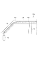
- an occupant protection device 10 a includes an A pillar (front pillar) 12, B that configures a curtain shield airbag 100 as a side wall of a vehicle compartment when a vehicle collides. It expands along the pillar (center pillar) 14, the C pillar (rear pillar) 16 and the roof side reinforcement 18 while being expanded.
- the deployed curtain shield airbag (CSA) 100 protects the passengers seated in the front seat 22 and the rear seat 24 from impacts from the side and diagonally forward of the vehicle.
- the curtain shield airbag 100 is normally folded and stored along the roof side reinforcement 18 at the vehicle canopy side end.
- a tether strap 102 for connecting the curtain shield airbag 100 and the vehicle body extends from the side end of the curtain shield airbag 100 along the A pillar 12.
- the lower end portion of the tether strap 102 is installed at the lower portion of the A pillar 12 and is connected to a pretensioner 110 that pulls the tether strap 102 with a force such as explosives when the vehicle collides.
- the pretensioner 110 applies tension to the tether strap 102 to reduce the slack.
- the tether strap 102 and the pretensioner 110 constitute a connecting unit in the present invention.
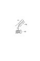
- the pretensioner 110 may be replaced with a retractor 120 with a reverse rotation prevention mechanism.
- the retractor 120 with the reverse rotation prevention mechanism winds the tether strap 102 with a reel in advance and applies a tension.
- the retractor 120 with the reverse rotation prevention mechanism winds up with the reel as much as the tether strap 102 is slackened.
- the retractor 120 with a reverse rotation prevention mechanism prevents the tether strap 102 once wound around the reel from returning to its original length by preventing the reel from rotating backward by a ratchet mechanism or the like.
- the retractor 120 with the reverse rotation prevention mechanism can keep the tether strap 102 at an appropriate length while preventing the tether strap 102 from being broken due to excessive tension at the time of collision.
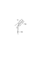
- the pretensioner 110 may be replaced with a spring mechanism 130.
- the spring mechanism 130 applies tension to the tether strap 102 with a spring in advance.
- the spring mechanism 130 reduces the slackness of the tether strap 102 due to the tension of the spring when the tether strap 102 is slackened at the time of collision.
- the spring mechanism 130 has a simple structure and can prevent the tether strap 102 from being broken due to an impact at the time of collision.
- the operation of the occupant protection device 10a of the present embodiment will be described.
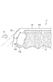
- the A pillar 12 may be deformed by the impact S, and the tether strap 102 may be slack.
- the pretensioner 110 applies tension to the tether strap 102 at the time of collision, and prevents the tether strap 102 from slackening. Therefore, the deployed curtain shield airbag 100 is firmly connected to the vehicle body by the tether strap 102 even if the vehicle body is deformed, and can protect the occupant at a predetermined position.
- the tether strap 102 is fixed to the vehicle body by a tether strap fixing portion 150. Therefore, as shown in FIG. 7, when the A pillar 12 is deformed by the impact S, the tether strap 102 may be loosened.
- the tether strap 102 that connects the curtain shield airbag 100 and the vehicle body of the vehicle
- a pretensioner 110 for reducing slack between the shield airbag 100 and the vehicle body is provided. For this reason, even when a slack occurs between the curtain shield airbag 100 and the vehicle body due to the deformation of the vehicle body that occurs at the time of the collision, the pretensioner 110 reduces the slack between the curtain shield airbag 100 and the vehicle body. Therefore, the passenger can be protected more effectively.
- the pretensioner 110, the retractor 120 with the reverse rotation prevention mechanism, and the spring mechanism 130 are provided in accordance with the amount of looseness generated between the curtain shield airbag 100 and the vehicle body due to the deformation of the vehicle body.
- the curtain shield airbag 100 and the vehicle body are drawn together. For this reason, even when a slack occurs between the curtain shield airbag 100 and the vehicle body due to the deformation of the vehicle body that occurs at the time of the collision, the slackness that occurs between the curtain shield airbag 100 and the vehicle body due to the deformation of the vehicle body.
- the curtain shield airbag 100 and the vehicle body are attracted to each other according to the amount, and the passenger can be more effectively protected.
- the pretensioner 110 generates a tension between the curtain shield airbag 100 and the vehicle body when the vehicle collides. For this reason, loosening between the curtain shield airbag 100 and the vehicle body caused by deformation of the vehicle body at the time of a collision can be effectively prevented, and the response is excellent.
- the retractor 120 with the reverse rotation prevention mechanism and the spring mechanism 130 generate tension between the curtain shield airbag 100 and the vehicle body in advance. For this reason, even when deformation occurs in the vehicle body due to the collision, loosening between the curtain shield airbag 100 and the vehicle body can be effectively prevented. Further, it is possible to prevent the tether strap 102 from being broken by an impact.
- the retractor 120 with the reverse rotation prevention mechanism can reduce the distance between the curtain shield airbag 100 and the vehicle body, and once reduces the distance between the curtain shield airbag 100 and the vehicle body. After this, it is impossible to increase the distance between the curtain shield airbag 100 and the vehicle body. For this reason, even when a slack occurs between the curtain shield airbag 100 and the vehicle body due to deformation of the vehicle body due to a collision, the distance between the curtain shield airbag 100 and the vehicle body once reduced does not return to the original. Sag can be prevented more effectively.
- the curtain shield airbag 100 is inflated and deployed along the side wall of the vehicle interior of the vehicle.
- a curtain shield airbag 100 is effective for protecting an occupant when a vehicle collides with an obstacle in a lateral direction or an obliquely forward direction.
- the curtain shield airbag 100 and the vehicle body are firmly connected regardless of the deformation of the vehicle, and the curtain shield airbag 100 is deployed at a predetermined position. Need to be. Therefore, the occupant protection device 10a provided with the pretensioner 110 of the present invention is particularly effective when the airbag is inflated and deployed along the side wall in the vehicle interior of the vehicle, such as the curtain shield airbag 100.
- the pretensioner 110 has a tether strap 102 that connects the front side of the curtain shield airbag 100 to the vehicle body and the A pillar of the vehicle body, and the pretensioner 110 pulls the tether strap 102 toward the vehicle body. To generate tension. For this reason, the occupant can be protected more effectively by reducing the looseness between the A-pillar 12 of the vehicle body and the curtain shield airbag 100.
- the tether strap 102 that connects the rear side of the curtain shield airbag 100 to the B pillar 14 of the vehicle body, or the rear side of the curtain shield airbag 100 and the C pillar 16 of the vehicle body is connected.
- the pretensioner 110 may include the tether strap 102 and generate tension by pulling the tether strap 102 toward the vehicle body. Thereby, the looseness between the B-pillar 14 or C-pillar 16 of the vehicle body and the curtain shield airbag 100 can be reduced, and the occupant can be protected more effectively.
- the pretensioner 110 is provided on the roof side reinforcement 18 at the rear of the A pillar 12 where the tether strap 102 and the vehicle body are connected. Also in this embodiment, it is possible to replace the pretensioner 110 with the retractor 120 with the reverse rotation prevention mechanism and the spring mechanism 130.
- the pretensioner 110 that generates tension that reduces the slack between the curtain shield airbag 100 and the vehicle body is more vehicle body than the A pillar 12 to which the curtain shield airbag 100 and the vehicle body are coupled.
- the rear side of the canopy is installed on the roof side reinforcement 18 of the canopy. Since the roof side reinforcement 18 is a portion that undergoes relatively little deformation even at the time of a collision, the occupant can be more effectively protected while preventing the influence of the deformation due to the collision.
- the pretensioner 110 is installed in the instrument panel reinforcement 20. Also in this embodiment, the pretensioner 110 can be replaced with the retractor 120 with the reverse rotation prevention mechanism and the spring mechanism 130.
- the pretensioner 110 that generates a tension that reduces the slack between the curtain shield airbag 100 and the vehicle body is installed in the instrument panel reinforcement 20.
- the instrument panel reinforcement 20 is a part that is relatively less deformed even at the time of a collision, and thus can protect the occupant more effectively while preventing the influence of the deformation due to the collision.
- the present invention is not limited to the above-described embodiments, and various modifications can be made.
- the aspect of connecting the A pillar 12 and the front end portion of the curtain shield airbag 100 has been mainly described.
- the technique of the above embodiment uses the rear end portion of the curtain shield airbag 100 as the B end.
- the present invention can be similarly applied when connecting to the pillar 14 or the C pillar 16.
- the occupant protection device of the present invention can protect the occupant more effectively.
Landscapes
- Engineering & Computer Science (AREA)
- Mechanical Engineering (AREA)
- Air Bags (AREA)
Abstract
カーテンシールドエアバッグ100を膨張させることにより車両の乗員を保護する乗員保護装置10aにおいて、カーテンシールドエアバッグ100と車両の車体とを連結するテザーストラップ102は、カーテンシールドエアバッグ100と車体との間の弛みを減少させるプリテンショナー110を有する。このため、衝突時において生じた車体の変形により、カーテンシールドエアバッグ100と車体との間に弛みが生じた場合でも、プリテンショナー110がカーテンシールドエアバッグ100と車体との間の弛みを減少させるため、より効果的に乗員を保護することができる。
Description
本発明は、乗員保護装置に関し、特にエアバッグを膨張させることにより車両の乗員を保護する乗員保護装置に関する。
エアバッグを膨張させることにより車両の乗員を保護する装置が提案されている。例えば、特許文献1には、車体の側方の窓部に沿って、上方から下方にエアバッグを展開する装置が開示されている。この装置では、エアバッグ本体の前側の下端部の被支持部と、フロントピラーの支持位置との間がストラップで繋がれている。エアバッグ本体がルーフサイド部に折り畳んで収納された状態で、ストラップはフロントピラーに沿って収納される。エアバッグが展開すると、被支持部は、初期位置から展開位置まで移動する。展開完了状態における支持位置と展開位置との離間寸法は、収納状態における支持位置と初期位置との離間寸法とほぼ等しくなるように配置される。ストラップは、エアバッグ本体の下部に結合し、展開完了状態において、支持位置に向かい上方に傾斜するように配置される。これにより、この装置では、自動車の側方の窓部を覆うカーテンエアバッグについて、ストラップによりエアバッグに張力を与えて安定して展開させる。
ところで、上記の技術では、ストラップによりエアバッグを車体に繋いでいるが、衝突時には車体が変形する可能性もあり得る。このため、膨張したエアバッグを所望の位置に固定するという点で改善の余地がある。
本発明は、このような事情を考慮してなされたものであり、その目的は、より効果的に乗員を保護することが可能な乗員保護装置を提供することにある。
本発明は、エアバッグを膨張させることにより車両の乗員を保護する乗員保護装置であって、エアバッグと車両の車体とを連結する連結ユニットを備え、連結ユニットは、エアバッグと車体との間の弛みを減少させる弛み防止機構を有する乗員保護装置である。
この構成によれば、エアバッグを膨張させることにより車両の乗員を保護する乗員保護装置において、エアバッグと車両の車体とを連結する連結ユニットは、エアバッグと車体との間の弛みを減少させる弛み防止機構を有する。このため、衝突時において生じた車体の変形により、エアバッグと車体との間に弛みが生じた場合でも、弛み防止機構がエアバッグと車体との間の弛みを減少させるため、より効果的に乗員を保護することができる。
この場合、弛み防止機構は、車体の変形によってエアバッグと車体との間に生じた弛みの量に応じて、エアバッグと車体とを互いに引き寄せるものとできる。
この構成によれば、弛み防止機構は、車体の変形によってエアバッグと車体との間に生じた緩みの量に応じて、エアバッグと車体とを互いに引き寄せる。このため、衝突時において生じた車体の変形により、エアバッグと車体との間に弛みが生じた場合でも、車体の変形によってエアバッグと車体との間に生じた緩みの量に応じてエアバッグと車体とが互いに引き寄せられ、さらに効果的に乗員を保護することができる。
また、弛み防止機構のエアバッグと車体との間の弛みを減少させる張力を発生させる張力発生源は、車体の車室の天蓋、エアバッグと車体とが連結されている部位よりも車体の後方の部位、及びインスツルパネルリインフォースのいずれかに設置されているものとできる。
この構成によれば、弛み防止機構のエアバッグと車体との間の弛みを減少させる張力を発生させる張力発生源は、車体の車室の天蓋、エアバッグと車体とが連結されている部位よりも車体の後方の部位及びインスツルパネルリインフォースのいずれかに設置されている。これらの車室の天蓋等は、衝突時においても変形が比較的に少ない部位であるため、衝突による変形の影響を防ぎつつ、より効果的に乗員を保護することができる。
また、エアバッグは、車両の車室内の側壁に沿って膨張して展開するものとできる。
この構成によれば、エアバッグは、車両の車室内の側壁に沿って膨張して展開する。このようなエアバッグは、車両が障害物に対して側方や斜め前方向で衝突した際に乗員を保護するために有効である。しかし、このようなエアバッグが効力を発揮するためには、エアバッグと車体とが車両の変形によらず強固に連結され、エアバッグが所定の位置に展開されている必要がある。そのため、本発明の弛み防止機構を備えた乗員保護装置は、エアバッグが車両の車室内の側壁に沿って膨張して展開するものである場合に特に効力を発揮する。
また、連結ユニットは、エアバッグの車体前方側と車体のフロントピラーとを連結するテザーストラップ、エアバッグの車体後方側と車体のセンターピラーとを連結するテザーストラップ、及びエアバッグの車体後方側と車体のリアーピラーとを連結するテザーストラップの少なくともいずれかを有し、緩み防止機構は、テザーストラップを車体側に引き寄せることで張力を発生させるものとできる。
この構成によれば、連結ユニットは、エアバッグの車体前方側と車体のフロントピラーとを連結するテザーストラップ、エアバッグの車体後方側と車体のセンターピラーとを連結するテザーストラップ、及びエアバッグの車体後方側と車体のリアーピラーとを連結するテザーストラップの少なくともいずれかを有し、緩み防止機構は、テザーストラップを車体側に引き寄せることで張力を発生させる。このため、車体のフロントピラー、センターピラー又はリアピラーとエアバッグとの間の緩みを減少させて、より効果的に乗員を保護することができる。
また、弛み防止機構は、予めエアバッグと車体との間に張力を発生させるものとできる。
この構成によれば、弛み防止機構は、予めエアバッグと車体との間に張力を発生させる。このため、衝突により車体に変形が生じたときでも、エアバッグと車体との間の緩みを効果的に防止することができる。
また、緩み防止機構は、車両の衝突時にエアバッグと車体との間に張力を発生させるものとできる。
この構成によれば、緩み防止機構は、車両の衝突時にエアバッグと車体との間に張力を発生させる。このため、衝突時において車体の変形により発生するエアバッグと車体との間の緩みを効果的に防止することができる。
また、緩み防止機構は、エアバッグと車体との距離を減少させることが可能であり、エアバッグと車体との距離を一度減少させた後は、エアバッグと車体との距離を増大させることは不可能とするものとできる。
この構成によれば、緩み防止機構は、エアバッグと車体との距離を減少させることが可能であり、エアバッグと車体との距離を一度減少させた後は、エアバッグと車体との距離を増大させることは不可能とする。このため、衝突による車体の変形により、エアバッグと車体との間に弛みが生じたときでも、一度減少させたエアバッグと車体との距離は元には戻らないため、より効果的に弛みを防止することができる。
本発明の乗員保護装置によれば、より効果的に乗員を保護することができる。
以下、図面を参照して本発明の実施形態に係る乗員保護装置について説明する。図1に示すように、本発明の第1実施形態の乗員保護装置10aは、車両の衝突時に、カーテンシールドエアバッグ100を車両の車室の側壁を構成するAピラー(フロントピラー)12、Bピラー(センターピラー)14、Cピラー(リアピラー)16及びルーフサイドリインフォース18に沿って膨張させつつ展開する。展開されたカーテンシールドエアバッグ(CSA:curtain shield airbag)100により、前部座席22及び後部座席24に着席した乗員は、車両の側方及び斜め前方からの衝撃から保護される。
図2に示すように、通常時には、カーテンシールドエアバッグ100は車室天蓋側端のルーフサイドリインフォース18に沿って折り畳まれて収納される。カーテンシールドエアバッグ100の側端部から、カーテンシールドエアバッグ100と車体とを連結するためのテザーストラップ102が、Aピラー12に沿って伸びている。テザーストラップ102の下端部は、Aピラー12下部に設置され、車両の衝突時に火薬等の力でテザーストラップ102を引っ張るプリテンショナー110と接続されている。プリテンショナー110は、衝突時にテザーストラップ102が弛んだときは、テザーストラップ102に張力を加えて弛みを減少させる。これらのテザーストラップ102と、プリテンショナー110とにより、本発明における連結ユニットが構成されている。
図3に示すように、プリテンショナー110は、逆回転防止機構付きリトラクタ120と置き換えても良い。逆回転防止機構付きリトラクタ120は、予めテザーストラップ102をリールで巻き取り、張力を加える。逆回転防止機構付きリトラクタ120は、衝突時にテザーストラップ102が弛んだときは、テザーストラップ102が弛んだ分だけリールで巻き取る。逆回転防止機構付きリトラクタ120は、ラチェット機構等によってリールの逆回転を防ぐことにより、一度リールに巻き取ったテザーストラップ102が元の長さに戻らないようにする。逆回転防止機構付きリトラクタ120は、衝突時にテザーストラップ102の過度の張力による破断を防止しつつ、テザーストラップ102を適当な長さに保つことができる。
図4に示すように、プリテンショナー110は、ばね機構130と置き換えても良い。ばね機構130は、予めテザーストラップ102にばねで張力を加える。ばね機構130は、衝突時にテザーストラップ102が弛んだときは、ばねの張力によりテザーストラップ102の弛みを減少させる。ばね機構130は、構造が簡単であり、衝突時にテザーストラップ102の衝撃による破断を防止することができる。
以下、本実施形態の乗員保護装置10aの動作について説明する。車両が斜め前方及び側方からの障害物と衝突したときは、図5に示すように、Aピラー12が衝撃Sにより変形し、テザーストラップ102に弛みが生じることがある。しかし、本実施形態では、プリテンショナー110が衝突時にテザーストラップ102に張力を加え、テザーストラップ102の弛みを防止する。そのため、展開されるカーテンシールドエアバッグ100は、車体が変形したとしてもテザーストラップ102により強固に車体と連結され、所定の位置で乗員を保護することが可能となる。
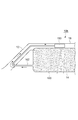
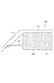
図6に示すように、従来の乗員保護装置1では、テザーストラップ102はテザーストラップ固定部150により車体と固定されている。そのため、図7に示すように、Aピラー12が衝撃Sにより変形したときは、テザーストラップ102に弛みが生じる可能性がある。
一方、本実施形態によれば、カーテンシールドエアバッグ100を膨張させることにより車両の乗員を保護する乗員保護装置10aにおいて、カーテンシールドエアバッグ100と車両の車体とを連結するテザーストラップ102は、カーテンシールドエアバッグ100と車体との間の弛みを減少させるプリテンショナー110を有する。このため、衝突時において生じた車体の変形により、カーテンシールドエアバッグ100と車体との間に弛みが生じた場合でも、プリテンショナー110がカーテンシールドエアバッグ100と車体との間の弛みを減少させるため、より効果的に乗員を保護することができる。
また、本実施形態によれば、プリテンショナー110、逆回転防止機構付きリトラクタ120及びばね機構130は、車体の変形によってカーテンシールドエアバッグ100と車体との間に生じた緩みの量に応じて、カーテンシールドエアバッグ100と車体とを互いに引き寄せる。このため、衝突時において生じた車体の変形により、カーテンシールドエアバッグ100と車体との間に弛みが生じた場合でも、車体の変形によってカーテンシールドエアバッグ100と車体との間に生じた緩みの量に応じてカーテンシールドエアバッグ100と車体とが互いに引き寄せられ、さらに効果的に乗員を保護することができる。
また、本実施形態によれば、プリテンショナー110は、車両の衝突時にカーテンシールドエアバッグ100と車体との間に張力を発生させる。このため、衝突時において車体の変形により発生するカーテンシールドエアバッグ100と車体との間の緩みを効果的に防止することができ、応答性に優れる。
また、本実施形態によれば、逆回転防止機構付きリトラクタ120及びばね機構130は、予めカーテンシールドエアバッグ100と車体との間に張力を発生させる。このため、衝突により車体に変形が生じたときでも、カーテンシールドエアバッグ100と車体との間の緩みを効果的に防止することができる。また、衝撃によりテザーストラップ102が破断することを防止することができる。
また、本実施形態によれば、逆回転防止機構付きリトラクタ120は、カーテンシールドエアバッグ100と車体との距離を減少させることが可能であり、カーテンシールドエアバッグ100と車体との距離を一度減少させた後は、カーテンシールドエアバッグ100と車体との距離を増大させることは不可能とする。このため、衝突による車体の変形により、カーテンシールドエアバッグ100と車体との間に弛みが生じたときでも、一度減少させたカーテンシールドエアバッグ100と車体との距離は元には戻らないため、より効果的に弛みを防止することができる。
また、本実施形態では、カーテンシールドエアバッグ100は、車両の車室内の側壁に沿って膨張して展開する。このようなカーテンシールドエアバッグ100は、車両が障害物に対して側方や斜め前方向で衝突した際に乗員を保護するために有効である。しかし、このようなカーテンシールドエアバッグ100が効力を発揮するためには、カーテンシールドエアバッグ100と車体とが車両の変形によらず強固に連結され、カーテンシールドエアバッグ100が所定の位置に展開されている必要がある。そのため、本発明のプリテンショナー110を備えた乗員保護装置10aは、カーテンシールドエアバッグ100のように、エアバッグが車両の車室内の側壁に沿って膨張して展開するものである場合に特に効力を発揮する。
また、本実施形態では、プリテンショナー110は、カーテンシールドエアバッグ100の車体前方側と車体のAピラーとを連結するテザーストラップ102を有し、プリテンショナー110は、テザーストラップ102を車体側に引き寄せることで張力を発生させる。このため、車体のAピラー12とカーテンシールドエアバッグ100との間の緩みを減少させて、より効果的に乗員を保護することができる。なお、本実施形態では、カーテンシールドエアバッグ100の車体後方側と車体のBピラー14とを連結するテザーストラップ102、あるいはカーテンシールドエアバッグ100の車体後方側と車体のCピラー16とを連結するテザーストラップ102を有し、プリテンショナー110は、これらのテザーストラップ102を車体側に引き寄せることで張力を発生させるものとしても良い。これにより、車体のBピラー14又はCピラー16とカーテンシールドエアバッグ100との間の緩みを減少させて、より効果的に乗員を保護することができる。
以下、本発明の第2実施形態について説明する。図8に示すように、本実施形態の乗員保護装置10bでは、プリテンショナー110が、テザーストラップ102と車体とが連結されるAピラー12よりも後部のルーフサイドリインフォース18に設けられている。本実施形態においても、プリテンショナー110を逆回転防止機構付きリトラクタ120及びばね機構130に替えることが可能である。
本実施形態によれば、カーテンシールドエアバッグ100と車体との間の弛みを減少させる張力を発生させるプリテンショナー110は、カーテンシールドエアバッグ100と車体とが連結されているAピラー12よりも車体の後方の部位であって天蓋のルーフサイドリインフォース18に設置されている。ルーフサイドリインフォース18は、衝突時においても変形が比較的に少ない部位であるため、衝突による変形の影響を防ぎつつ、より効果的に乗員を保護することができる。
以下、本発明の第3実施形態について説明する。図9及び図10に示すように、本実施形態の乗員保護装置10cでは、プリテンショナー110が、インスツルパネルリインフォース20に設置されている。本実施形態においても、プリテンショナー110を逆回転防止機構付きリトラクタ120及びばね機構130に替えることが可能である。
本実施形態によれば、カーテンシールドエアバッグ100と車体との間の弛みを減少させる張力を発生させるプリテンショナー110は、インスツルパネルリインフォース20に設置されている。インスツルパネルリインフォース20は、衝突時においても変形が比較的に少ない部位であるため、衝突による変形の影響を防ぎつつ、より効果的に乗員を保護することができる。
以上、本発明の実施の形態について説明したが、本発明は、上記実施形態に限定されるものではなく種々の変形が可能である。例えば、上記実施形態においては、Aピラー12とカーテンシールドエアバッグ100の前端部とを連結する態様について中心に説明したが、上記実施形態の技術は、カーテンシールドエアバッグ100の後端部をBピラー14やCピラー16に連結する場合にも同様に適用可能である。
本発明の乗員保護装置によれば、より効果的に乗員を保護することができる。
1 乗員保護装置
10a,10b,10b 乗員保護装置
12 Aピラー(フロントピラー)
14 Bピラー(センターピラー)
16 Cピラー(リアピラー)
18 ルーフサイドリインフォース
20 インスツルパネルリインフォース
22 前部座席
24 後部座席
100 カーテンシールドエアバッグ
102 テザーストラップ
110 プリテンショナー
120 逆回転防止機構付きリトラクタ
130 ばね機構
150 テザーストラップ固定部
10a,10b,10b 乗員保護装置
12 Aピラー(フロントピラー)
14 Bピラー(センターピラー)
16 Cピラー(リアピラー)
18 ルーフサイドリインフォース
20 インスツルパネルリインフォース
22 前部座席
24 後部座席
100 カーテンシールドエアバッグ
102 テザーストラップ
110 プリテンショナー
120 逆回転防止機構付きリトラクタ
130 ばね機構
150 テザーストラップ固定部
Claims (8)
- エアバッグを膨張させることにより車両の乗員を保護する乗員保護装置であって、
前記エアバッグと前記車両の車体とを連結する連結ユニットを備え、
前記連結ユニットは、前記エアバッグと前記車体との間の弛みを減少させる弛み防止機構を有する、乗員保護装置。 - 前記弛み防止機構は、前記車体の変形によって前記エアバッグと前記車体との間に生じた弛みの量に応じて、前記エアバッグと前記車体とを互いに引き寄せる、請求項1に記載の乗員保護装置。
- 前記弛み防止機構の前記エアバッグと前記車体との間の弛みを減少させる張力を発生させる張力発生源は、前記車体の車室の天蓋、前記エアバッグと前記車体とが連結されている部位よりも前記車体の後方の部位、及びインスツルパネルリインフォースのいずれかに設置されている、請求項1又は2に記載の乗員保護装置。
- 前記エアバッグは、前記車両の車室内の側壁に沿って膨張して展開する、請求項1~3のいずれか1項に記載の乗員保護装置。
- 前記連結ユニットは、前記エアバッグの前記車体前方側と前記車体のフロントピラーとを連結するテザーストラップ、前記エアバッグの前記車体後方側と前記車体のセンターピラーとを連結するテザーストラップ、及び前記エアバッグの前記車体後方側と前記車体のリアーピラーとを連結するテザーストラップの少なくともいずれかを有し、
前記緩み防止機構は、前記テザーストラップを前記車体側に引き寄せることで張力を発生させる、請求項1~4のいずれか1項に記載の乗員保護装置。 - 前記弛み防止機構は、予め前記エアバッグと前記車体との間に張力を発生させる、請求項1~5のいずれか1項に記載の乗員保護装置。
- 前記緩み防止機構は、前記車両の衝突時に前記エアバッグと前記車体との間に張力を発生させる、請求項1~5のいずれか1項に記載の乗員保護装置。
- 前記緩み防止機構は、前記エアバッグと前記車体との距離を減少させることが可能であり、前記エアバッグと前記車体との距離を一度減少させた後は、前記エアバッグと前記車体との距離を増大させることは不可能とする、請求項1~7のいずれか1項に記載の乗員保護装置。
Priority Applications (1)
| Application Number | Priority Date | Filing Date | Title |
|---|---|---|---|
| PCT/JP2011/052285 WO2012105027A1 (ja) | 2011-02-03 | 2011-02-03 | 乗員保護装置 |
Applications Claiming Priority (1)
| Application Number | Priority Date | Filing Date | Title |
|---|---|---|---|
| PCT/JP2011/052285 WO2012105027A1 (ja) | 2011-02-03 | 2011-02-03 | 乗員保護装置 |
Publications (1)
| Publication Number | Publication Date |
|---|---|
| WO2012105027A1 true WO2012105027A1 (ja) | 2012-08-09 |
Family
ID=46602268
Family Applications (1)
| Application Number | Title | Priority Date | Filing Date |
|---|---|---|---|
| PCT/JP2011/052285 Ceased WO2012105027A1 (ja) | 2011-02-03 | 2011-02-03 | 乗員保護装置 |
Country Status (1)
| Country | Link |
|---|---|
| WO (1) | WO2012105027A1 (ja) |
Citations (12)
| Publication number | Priority date | Publication date | Assignee | Title |
|---|---|---|---|---|
| JPH05193430A (ja) * | 1991-11-22 | 1993-08-03 | Takata Kk | 自動車の乗員頭部の保護装置 |
| DE19519297A1 (de) * | 1994-06-03 | 1995-12-07 | Volkswagen Ag | Sicherheitseinrichtung für ein Fahrzeug |
| JPH09175303A (ja) * | 1995-12-22 | 1997-07-08 | Toyoda Gosei Co Ltd | 乗員保護装置 |
| JPH10315893A (ja) * | 1997-05-15 | 1998-12-02 | Toyota Motor Corp | 自動車用乗員保護装置 |
| GB2327066A (en) * | 1997-07-09 | 1999-01-13 | Autoliv Dev | Improvements in or relating to an air-bag |
| JPH11124002A (ja) * | 1997-08-20 | 1999-05-11 | Takata Kk | 自動車用安全装置 |
| JP2001171466A (ja) * | 1999-12-06 | 2001-06-26 | Trw Occupant Restraint Syst Gmbh & Co Kg | 自動車用側方衝撃保護システム |
| JP2002520220A (ja) * | 1998-07-16 | 2002-07-09 | ティーアールダブリュー・オキュパント・リストレイント・システムズ・ゲーエムベーハー・ウント・コンパニー・カーゲー | 車両の拘束モジュール |
| JP2006096159A (ja) * | 2004-09-29 | 2006-04-13 | Toyoda Gosei Co Ltd | 乗員拘束装置 |
| JP2006103411A (ja) * | 2004-10-01 | 2006-04-20 | Toyoda Gosei Co Ltd | 乗員拘束装置 |
| JP2006123687A (ja) * | 2004-10-28 | 2006-05-18 | Toyoda Gosei Co Ltd | 乗員拘束装置 |
| JP2006315486A (ja) * | 2005-05-11 | 2006-11-24 | Toyoda Gosei Co Ltd | 乗員拘束装置 |
-
2011
- 2011-02-03 WO PCT/JP2011/052285 patent/WO2012105027A1/ja not_active Ceased
Patent Citations (12)
| Publication number | Priority date | Publication date | Assignee | Title |
|---|---|---|---|---|
| JPH05193430A (ja) * | 1991-11-22 | 1993-08-03 | Takata Kk | 自動車の乗員頭部の保護装置 |
| DE19519297A1 (de) * | 1994-06-03 | 1995-12-07 | Volkswagen Ag | Sicherheitseinrichtung für ein Fahrzeug |
| JPH09175303A (ja) * | 1995-12-22 | 1997-07-08 | Toyoda Gosei Co Ltd | 乗員保護装置 |
| JPH10315893A (ja) * | 1997-05-15 | 1998-12-02 | Toyota Motor Corp | 自動車用乗員保護装置 |
| GB2327066A (en) * | 1997-07-09 | 1999-01-13 | Autoliv Dev | Improvements in or relating to an air-bag |
| JPH11124002A (ja) * | 1997-08-20 | 1999-05-11 | Takata Kk | 自動車用安全装置 |
| JP2002520220A (ja) * | 1998-07-16 | 2002-07-09 | ティーアールダブリュー・オキュパント・リストレイント・システムズ・ゲーエムベーハー・ウント・コンパニー・カーゲー | 車両の拘束モジュール |
| JP2001171466A (ja) * | 1999-12-06 | 2001-06-26 | Trw Occupant Restraint Syst Gmbh & Co Kg | 自動車用側方衝撃保護システム |
| JP2006096159A (ja) * | 2004-09-29 | 2006-04-13 | Toyoda Gosei Co Ltd | 乗員拘束装置 |
| JP2006103411A (ja) * | 2004-10-01 | 2006-04-20 | Toyoda Gosei Co Ltd | 乗員拘束装置 |
| JP2006123687A (ja) * | 2004-10-28 | 2006-05-18 | Toyoda Gosei Co Ltd | 乗員拘束装置 |
| JP2006315486A (ja) * | 2005-05-11 | 2006-11-24 | Toyoda Gosei Co Ltd | 乗員拘束装置 |
Similar Documents
| Publication | Publication Date | Title |
|---|---|---|
| US7441796B2 (en) | Airbag system | |
| JP6386361B2 (ja) | 車両用カーテンエアバッグを収納したルーフヘッドライニング構造 | |
| WO2010089847A1 (ja) | 乗用車用頭部保護エアバッグ装置 | |
| JP2011148431A (ja) | 後突用エアバッグ装置 | |
| US11148633B2 (en) | Vehicle airbag device | |
| US7234728B2 (en) | Airbag system | |
| WO2012147490A1 (ja) | カーテンエアバッグ装置 | |
| JP5163309B2 (ja) | 車両の内装構造 | |
| JP6872373B2 (ja) | エアバッグ | |
| JP5988611B2 (ja) | エアバッグ装置 | |
| JP6577298B2 (ja) | エアバッグ装置 | |
| JP6420157B2 (ja) | エアバッグ | |
| JP2008137458A (ja) | エアバッグ装置 | |
| JP2011218994A (ja) | 車両用カーテンエアバッグ装置 | |
| JP2010083240A (ja) | エアバッグ及びエアバッグ装置 | |
| JP5217847B2 (ja) | 車両の遮蔽部材の取付け構造 | |
| JP5151867B2 (ja) | カーテンエアバッグを備えた車両の内装構造 | |
| JP2008195190A (ja) | 車両用エアバッグ装置 | |
| KR100831438B1 (ko) | 자동차용 커튼에어백의 전개 유도장치 | |
| JP6329051B2 (ja) | エアバッグ装置 | |
| WO2012105027A1 (ja) | 乗員保護装置 | |
| JP2007076517A (ja) | 頭部保護エアバッグ装置 | |
| JP5034552B2 (ja) | カーテンエアバッグ装置を備えた車両の後部構造 | |
| JP6580480B2 (ja) | カーテンエアバッグ装置 | |
| KR102928637B1 (ko) | 차량용 루프에어백 장치 |
Legal Events
| Date | Code | Title | Description |
|---|---|---|---|
| 121 | Ep: the epo has been informed by wipo that ep was designated in this application |
Ref document number: 11857834 Country of ref document: EP Kind code of ref document: A1 |
|
| NENP | Non-entry into the national phase |
Ref country code: DE |
|
| 122 | Ep: pct application non-entry in european phase |
Ref document number: 11857834 Country of ref document: EP Kind code of ref document: A1 |
|
| NENP | Non-entry into the national phase |
Ref country code: JP |