WO2012102336A1 - 封止用エポキシ樹脂組成物及び電子部品装置 - Google Patents
封止用エポキシ樹脂組成物及び電子部品装置 Download PDFInfo
- Publication number
- WO2012102336A1 WO2012102336A1 PCT/JP2012/051648 JP2012051648W WO2012102336A1 WO 2012102336 A1 WO2012102336 A1 WO 2012102336A1 JP 2012051648 W JP2012051648 W JP 2012051648W WO 2012102336 A1 WO2012102336 A1 WO 2012102336A1
- Authority
- WO
- WIPO (PCT)
- Prior art keywords
- epoxy resin
- resin composition
- group
- sealing
- electronic component
- Prior art date
- Legal status (The legal status is an assumption and is not a legal conclusion. Google has not performed a legal analysis and makes no representation as to the accuracy of the status listed.)
- Ceased
Links
Images

Classifications
-
- H—ELECTRICITY
- H10—SEMICONDUCTOR DEVICES; ELECTRIC SOLID-STATE DEVICES NOT OTHERWISE PROVIDED FOR
- H10W—GENERIC PACKAGES, INTERCONNECTIONS, CONNECTORS OR OTHER CONSTRUCTIONAL DETAILS OF DEVICES COVERED BY CLASS H10
- H10W74/00—Encapsulations, e.g. protective coatings
- H10W74/40—Encapsulations, e.g. protective coatings characterised by their materials
- H10W74/47—Encapsulations, e.g. protective coatings characterised by their materials comprising organic materials, e.g. plastics or resins
- H10W74/476—Organic materials comprising silicon
-
- C—CHEMISTRY; METALLURGY
- C08—ORGANIC MACROMOLECULAR COMPOUNDS; THEIR PREPARATION OR CHEMICAL WORKING-UP; COMPOSITIONS BASED THEREON
- C08G—MACROMOLECULAR COMPOUNDS OBTAINED OTHERWISE THAN BY REACTIONS ONLY INVOLVING UNSATURATED CARBON-TO-CARBON BONDS
- C08G59/00—Polycondensates containing more than one epoxy group per molecule; Macromolecules obtained by polymerising compounds containing more than one epoxy group per molecule using curing agents or catalysts which react with the epoxy groups
- C08G59/18—Macromolecules obtained by polymerising compounds containing more than one epoxy group per molecule using curing agents or catalysts which react with the epoxy groups ; e.g. general methods of curing
- C08G59/40—Macromolecules obtained by polymerising compounds containing more than one epoxy group per molecule using curing agents or catalysts which react with the epoxy groups ; e.g. general methods of curing characterised by the curing agents used
- C08G59/4007—Curing agents not provided for by the groups C08G59/42 - C08G59/66
- C08G59/4071—Curing agents not provided for by the groups C08G59/42 - C08G59/66 phosphorus containing compounds
-
- C—CHEMISTRY; METALLURGY
- C08—ORGANIC MACROMOLECULAR COMPOUNDS; THEIR PREPARATION OR CHEMICAL WORKING-UP; COMPOSITIONS BASED THEREON
- C08G—MACROMOLECULAR COMPOUNDS OBTAINED OTHERWISE THAN BY REACTIONS ONLY INVOLVING UNSATURATED CARBON-TO-CARBON BONDS
- C08G59/00—Polycondensates containing more than one epoxy group per molecule; Macromolecules obtained by polymerising compounds containing more than one epoxy group per molecule using curing agents or catalysts which react with the epoxy groups
- C08G59/18—Macromolecules obtained by polymerising compounds containing more than one epoxy group per molecule using curing agents or catalysts which react with the epoxy groups ; e.g. general methods of curing
- C08G59/40—Macromolecules obtained by polymerising compounds containing more than one epoxy group per molecule using curing agents or catalysts which react with the epoxy groups ; e.g. general methods of curing characterised by the curing agents used
- C08G59/62—Alcohols or phenols
- C08G59/621—Phenols
-
- C—CHEMISTRY; METALLURGY
- C08—ORGANIC MACROMOLECULAR COMPOUNDS; THEIR PREPARATION OR CHEMICAL WORKING-UP; COMPOSITIONS BASED THEREON
- C08G—MACROMOLECULAR COMPOUNDS OBTAINED OTHERWISE THAN BY REACTIONS ONLY INVOLVING UNSATURATED CARBON-TO-CARBON BONDS
- C08G59/00—Polycondensates containing more than one epoxy group per molecule; Macromolecules obtained by polymerising compounds containing more than one epoxy group per molecule using curing agents or catalysts which react with the epoxy groups
- C08G59/18—Macromolecules obtained by polymerising compounds containing more than one epoxy group per molecule using curing agents or catalysts which react with the epoxy groups ; e.g. general methods of curing
- C08G59/68—Macromolecules obtained by polymerising compounds containing more than one epoxy group per molecule using curing agents or catalysts which react with the epoxy groups ; e.g. general methods of curing characterised by the catalysts used
- C08G59/688—Macromolecules obtained by polymerising compounds containing more than one epoxy group per molecule using curing agents or catalysts which react with the epoxy groups ; e.g. general methods of curing characterised by the catalysts used containing phosphorus
-
- C—CHEMISTRY; METALLURGY
- C08—ORGANIC MACROMOLECULAR COMPOUNDS; THEIR PREPARATION OR CHEMICAL WORKING-UP; COMPOSITIONS BASED THEREON
- C08K—Use of inorganic or non-macromolecular organic substances as compounding ingredients
- C08K3/00—Use of inorganic substances as compounding ingredients
- C08K3/34—Silicon-containing compounds
- C08K3/36—Silica
-
- C—CHEMISTRY; METALLURGY
- C08—ORGANIC MACROMOLECULAR COMPOUNDS; THEIR PREPARATION OR CHEMICAL WORKING-UP; COMPOSITIONS BASED THEREON
- C08K—Use of inorganic or non-macromolecular organic substances as compounding ingredients
- C08K7/00—Use of ingredients characterised by shape
- C08K7/16—Solid spheres
- C08K7/18—Solid spheres inorganic
-
- C—CHEMISTRY; METALLURGY
- C08—ORGANIC MACROMOLECULAR COMPOUNDS; THEIR PREPARATION OR CHEMICAL WORKING-UP; COMPOSITIONS BASED THEREON
- C08L—COMPOSITIONS OF MACROMOLECULAR COMPOUNDS
- C08L63/00—Compositions of epoxy resins; Compositions of derivatives of epoxy resins
-
- H—ELECTRICITY
- H10—SEMICONDUCTOR DEVICES; ELECTRIC SOLID-STATE DEVICES NOT OTHERWISE PROVIDED FOR
- H10W—GENERIC PACKAGES, INTERCONNECTIONS, CONNECTORS OR OTHER CONSTRUCTIONAL DETAILS OF DEVICES COVERED BY CLASS H10
- H10W70/00—Package substrates; Interposers; Redistribution layers [RDL]
- H10W70/40—Leadframes
- H10W70/456—Materials
- H10W70/458—Materials of insulating layers on leadframes
-
- H—ELECTRICITY
- H10—SEMICONDUCTOR DEVICES; ELECTRIC SOLID-STATE DEVICES NOT OTHERWISE PROVIDED FOR
- H10W—GENERIC PACKAGES, INTERCONNECTIONS, CONNECTORS OR OTHER CONSTRUCTIONAL DETAILS OF DEVICES COVERED BY CLASS H10
- H10W72/00—Interconnections or connectors in packages
- H10W72/851—Dispositions of multiple connectors or interconnections
-
- H—ELECTRICITY
- H10—SEMICONDUCTOR DEVICES; ELECTRIC SOLID-STATE DEVICES NOT OTHERWISE PROVIDED FOR
- H10W—GENERIC PACKAGES, INTERCONNECTIONS, CONNECTORS OR OTHER CONSTRUCTIONAL DETAILS OF DEVICES COVERED BY CLASS H10
- H10W74/00—Encapsulations, e.g. protective coatings
- H10W74/10—Encapsulations, e.g. protective coatings characterised by their shape or disposition
- H10W74/111—Encapsulations, e.g. protective coatings characterised by their shape or disposition the semiconductor body being completely enclosed
-
- H—ELECTRICITY
- H10—SEMICONDUCTOR DEVICES; ELECTRIC SOLID-STATE DEVICES NOT OTHERWISE PROVIDED FOR
- H10W—GENERIC PACKAGES, INTERCONNECTIONS, CONNECTORS OR OTHER CONSTRUCTIONAL DETAILS OF DEVICES COVERED BY CLASS H10
- H10W74/00—Encapsulations, e.g. protective coatings
- H10W74/40—Encapsulations, e.g. protective coatings characterised by their materials
- H10W74/47—Encapsulations, e.g. protective coatings characterised by their materials comprising organic materials, e.g. plastics or resins
- H10W74/473—Encapsulations, e.g. protective coatings characterised by their materials comprising organic materials, e.g. plastics or resins containing a filler
-
- H—ELECTRICITY
- H10—SEMICONDUCTOR DEVICES; ELECTRIC SOLID-STATE DEVICES NOT OTHERWISE PROVIDED FOR
- H10W—GENERIC PACKAGES, INTERCONNECTIONS, CONNECTORS OR OTHER CONSTRUCTIONAL DETAILS OF DEVICES COVERED BY CLASS H10
- H10W90/00—Package configurations
- H10W90/811—Multiple chips on leadframes
-
- H—ELECTRICITY
- H10—SEMICONDUCTOR DEVICES; ELECTRIC SOLID-STATE DEVICES NOT OTHERWISE PROVIDED FOR
- H10W—GENERIC PACKAGES, INTERCONNECTIONS, CONNECTORS OR OTHER CONSTRUCTIONAL DETAILS OF DEVICES COVERED BY CLASS H10
- H10W72/00—Interconnections or connectors in packages
- H10W72/851—Dispositions of multiple connectors or interconnections
- H10W72/874—On different surfaces
- H10W72/884—Die-attach connectors and bond wires
-
- H—ELECTRICITY
- H10—SEMICONDUCTOR DEVICES; ELECTRIC SOLID-STATE DEVICES NOT OTHERWISE PROVIDED FOR
- H10W—GENERIC PACKAGES, INTERCONNECTIONS, CONNECTORS OR OTHER CONSTRUCTIONAL DETAILS OF DEVICES COVERED BY CLASS H10
- H10W90/00—Package configurations
- H10W90/701—Package configurations characterised by the relative positions of pads or connectors relative to package parts
- H10W90/731—Package configurations characterised by the relative positions of pads or connectors relative to package parts of die-attach connectors
- H10W90/732—Package configurations characterised by the relative positions of pads or connectors relative to package parts of die-attach connectors between stacked chips
-
- H—ELECTRICITY
- H10—SEMICONDUCTOR DEVICES; ELECTRIC SOLID-STATE DEVICES NOT OTHERWISE PROVIDED FOR
- H10W—GENERIC PACKAGES, INTERCONNECTIONS, CONNECTORS OR OTHER CONSTRUCTIONAL DETAILS OF DEVICES COVERED BY CLASS H10
- H10W90/00—Package configurations
- H10W90/701—Package configurations characterised by the relative positions of pads or connectors relative to package parts
- H10W90/731—Package configurations characterised by the relative positions of pads or connectors relative to package parts of die-attach connectors
- H10W90/736—Package configurations characterised by the relative positions of pads or connectors relative to package parts of die-attach connectors between a chip and a stacked lead frame, conducting package substrate or heat sink
-
- H—ELECTRICITY
- H10—SEMICONDUCTOR DEVICES; ELECTRIC SOLID-STATE DEVICES NOT OTHERWISE PROVIDED FOR
- H10W—GENERIC PACKAGES, INTERCONNECTIONS, CONNECTORS OR OTHER CONSTRUCTIONAL DETAILS OF DEVICES COVERED BY CLASS H10
- H10W90/00—Package configurations
- H10W90/701—Package configurations characterised by the relative positions of pads or connectors relative to package parts
- H10W90/751—Package configurations characterised by the relative positions of pads or connectors relative to package parts of bond wires
- H10W90/752—Package configurations characterised by the relative positions of pads or connectors relative to package parts of bond wires between stacked chips
-
- H—ELECTRICITY
- H10—SEMICONDUCTOR DEVICES; ELECTRIC SOLID-STATE DEVICES NOT OTHERWISE PROVIDED FOR
- H10W—GENERIC PACKAGES, INTERCONNECTIONS, CONNECTORS OR OTHER CONSTRUCTIONAL DETAILS OF DEVICES COVERED BY CLASS H10
- H10W90/00—Package configurations
- H10W90/701—Package configurations characterised by the relative positions of pads or connectors relative to package parts
- H10W90/751—Package configurations characterised by the relative positions of pads or connectors relative to package parts of bond wires
- H10W90/756—Package configurations characterised by the relative positions of pads or connectors relative to package parts of bond wires between a chip and a stacked lead frame, conducting package substrate or heat sink
Definitions
- the present invention relates to a sealing epoxy resin composition and an electronic component device. More specifically, when a copper lead frame is used, an epoxy resin composition for sealing excellent in adhesion to copper that has undergone oxidation and releasability from a molding die, and an epoxy resin for sealing the same
- the present invention relates to an electronic component device in which an electronic component is sealed with a cured product of the composition.
- a bonding wire is thermocompression bonded between an aluminum electrode of a semiconductor element (hereinafter also referred to as “semiconductor chip”) and an inner lead of a lead frame.
- semiconductor chip a semiconductor element
- the method of electrical connection is now mainstream.
- the integration of electronic components and the increase in the number of pins are progressing year by year. For this reason, a more complicated wire bonding process is required than before, and when a copper lead frame is used, the copper surface is further oxidized by being exposed to a high temperature of 200 to 250 ° C. for a long time. It has become like this.
- the present invention has been made in view of such circumstances, and has an epoxy resin composition for sealing that has good adhesion to a copper lead frame that has undergone oxidation, and that has excellent mold release and continuous moldability, and a cured product thereof.
- an electronic component device in which the electronic component is sealed is provided.
- the present inventors have found that a specific phosphobetaine compound, an adduct of a phosphine compound and a quinone compound, and a phosphonium compound and a silane are added to the epoxy resin composition for sealing.
- the inventors have found that the above-mentioned object can be achieved by using at least one curing accelerator selected from the group consisting of adducts with a compound after adjusting to a specific particle size distribution, thereby completing the present invention. It was.
- the epoxy resin composition for sealing of the present invention is an epoxy resin composition for sealing containing (A) an epoxy resin, (B) a phenol resin-based curing agent, (C) an inorganic filler, and (D) a curing accelerator.
- the (D) curing accelerator has an average particle size of 10 ⁇ m or less and a ratio of particles having a particle size exceeding 20 ⁇ m is 1% by mass or less
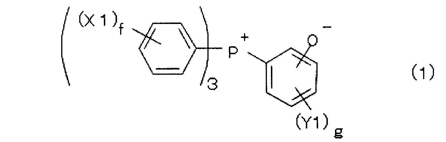
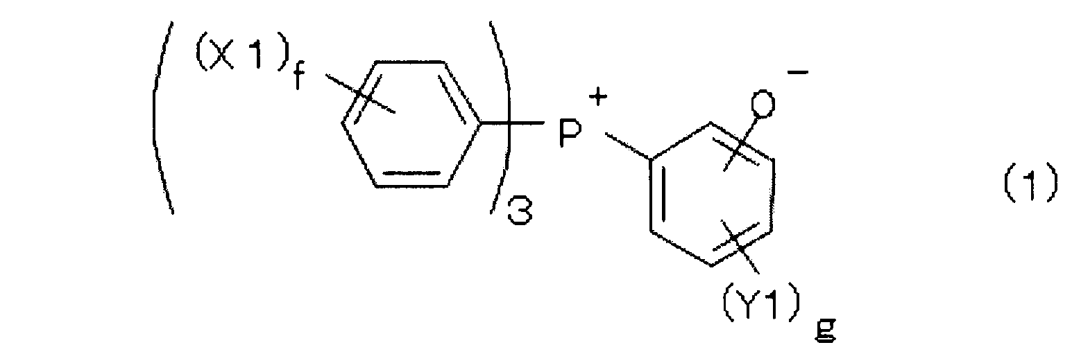
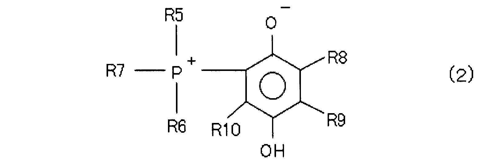
- the (D) curing accelerator is The following general formula (1): (In the above general formula (1), P represents a phosphorus atom, X1 represents an alkyl group having 1 to 3 carbon atoms, Y1 represents a hydroxyl group, f is an integer of 0 to 5, and g is 0 to It is an integer of 3.) A compound represented by The following general formula (2): (In the above general formula (2), P represents a phosphorus atom.
- R5, R6 and R7 each represents an alkyl group having 1 to 12 carbon atoms or an aryl group having 6 to 12 carbon atoms, and may be the same as each other
- R8, R9 and R10 each represents a hydrogen atom or a hydrocarbon group having 1 to 12 carbon atoms, which may be the same or different from each other, and R8 and R9 are bonded to form a cyclic structure; It may be.
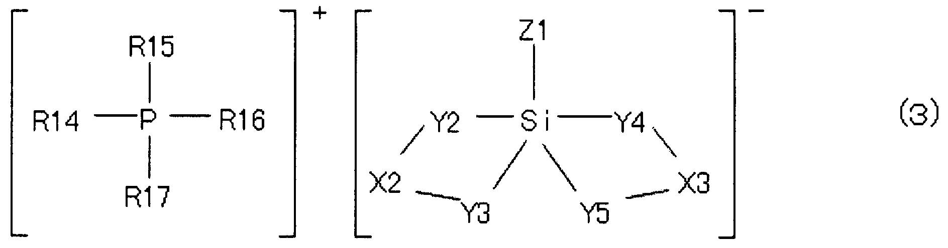
- R14, R15, R16 and R17 are each an organic group having an aromatic ring or a heterocyclic ring, or an aliphatic group.
- X2 is an organic group bonded to the groups Y2 and Y3, where X3 is an organic group bonded to the groups Y4 and Y5.
- Y2 and Y3 represent a group formed by releasing a proton from a proton donating group, and groups Y2 and Y3 in the same molecule are combined with a silicon atom to form a chelate structure.
- the donating group represents a group formed by releasing a proton, and groups Y4 and Y5 in the same molecule are bonded to a silicon atom to form a chelate structure.
- X2 and X3 are the same or different from each other May
- Group Y2, Y3, Y4, and Y5 is .Z1 which may be the same or different from each other is an organic group or an aliphatic group, an aromatic ring or a heterocyclic ring.) It contains at least 1 sort (s) of hardening accelerator chosen from the group which consists of a compound represented by these.
- the epoxy resin composition for sealing of the present invention can have an adhesive strength of 14 N or more with copper oxide in the following measurement experiment.
- ⁇ Measurement experiment> Integrated molding of the tableted epoxy resin composition and the copper oxide base material whose surface has been oxidized by heat treatment at 220 ° C for 120 seconds under the atmosphere at 175 ° C, 6.9 MPa for 2 minutes Then, a frustum-shaped molded product (upper diameter 3 mm ⁇ lower diameter 3.6 mm ⁇ thickness 3 mm, copper oxide base material and resin cured product) on a copper oxide base material (diameter 3.6 mm, thickness 0.5 mm) after obtaining a contact area 10 mm 2) of, press cure site of the epoxy resin composition from the side, and measuring the torque (N).
- the sealing epoxy resin composition of the present invention can be applied to a copper surface or a copper oxide surface.
- the epoxy resin composition for sealing according to the present invention may be characterized in that the (C) inorganic filler contains fused spherical silica having an average particle size of 10 to 30 ⁇ m.
- the epoxy resin composition for sealing of the present invention may be characterized in that the fused spherical silica is contained in the total resin composition in a proportion of 82% by mass or more and 92% by mass or less.
- the (A) epoxy resin may contain a bifunctional crystalline epoxy resin.
- the electronic component device of the present invention is characterized in that the electronic component is sealed with a cured product of the above-described sealing epoxy resin composition.
- the electronic component is mounted on a die pad of a copper lead frame, and the electrode pad of the electronic component and the inner lead of the copper lead frame are connected by a bonding wire. it can.
- two or more electronic components may be stacked and mounted on the die pad of the copper lead frame.
- an epoxy resin composition for sealing that is excellent in adhesion to a copper lead frame that has undergone oxidation, and has excellent mold release and continuous moldability.
- an electronic component device having excellent reliability in which electronic components such as IC and LSI are sealed with this sealing epoxy resin composition can be obtained.
- the epoxy resin composition for sealing of the present invention is an epoxy resin composition for sealing containing (A) an epoxy resin, (B) a phenol resin-based curing agent, (C) an inorganic filler, and (D) a curing accelerator. And (D) the curing accelerator has an average particle size of 10 ⁇ m or less and the proportion of particles having a particle size exceeding 20 ⁇ m is 1% by mass or less, and (D) the curing accelerator is represented by the general formula (1) And at least one curing accelerator selected from the group consisting of a compound represented by general formula (2) and a compound represented by general formula (3).
- the electronic component device of the present invention is characterized in that electronic components such as IC and LSI are sealed with a cured product of the sealing epoxy resin composition. Thereby, the electronic component apparatus excellent in reliability can be obtained.
- the present invention will be described in detail.
- the epoxy resin of component (A) used in the epoxy resin composition for sealing of the present invention is generally used in the epoxy resin composition for sealing and is not particularly limited.
- a phenol novolac type epoxy resin Phenols such as ortho-cresol novolac type epoxy resin, phenols, cresol, xylenol, resorcin, catechol, bisphenol A, bisphenol F, etc.
- the epoxy resin etc. which were made are mentioned, These may be used independently or may be used in combination of 2 or more type. Among them, bisphenol A type epoxy resin, bisphenol F type epoxy resin, tetraalkyl substituted bisphenol A type epoxy resin, bisphenol type epoxy resin such as tetraalkyl substituted bisphenol F type epoxy resin, bifunctional crystallinity such as biphenyl type epoxy resin, etc. Epoxy resins are preferred, and biphenyl type epoxy resins are particularly preferred from the viewpoint of adhesion to copper that has undergone oxidation.
- the epoxy resin composition for all sealing 1 mass% or more, It is preferably 15% by mass or less, and more preferably 2% by mass or more and 10% by mass or less.
- the blending ratio of the entire epoxy resin as the component (A) is not less than the above lower limit, there is little possibility of causing a decrease in fluidity.
- the blending ratio of the entire epoxy resin of the component (A) is not more than the above upper limit value, there is little possibility of causing a decrease in solder resistance.
- the phenol resin-based curing agent of component (B) used in the epoxy resin composition for sealing of the present invention is generally used in the epoxy resin composition for sealing and is not particularly limited.
- phenol novolak Resin phenols such as cresol novolac resin, cresol, resorcin, catechol, bisphenol A, bisphenol F, phenylphenol, aminophenol and other phenols and / or naphthols such as ⁇ -naphthol, ⁇ -naphthol, dihydroxynaphthalene and the like
- Resins, phenols and / or naphthols and dimethoxy obtained by condensation or cocondensation with compounds having an aldehyde group such as formaldehyde, acetaldehyde, propionaldehyde, benzaldehyde, salicylaldehyde, etc.
- phenol aralkyl resins synthesized from cyparaxylene, bis (methoxymethyl) biphenyl, bishaloparaxylene, or bishalomethylbiphenyl, and these may be used alone or in combination of two or more. Of these, phenol aralkyl resins are preferred from the viewpoint of adhesion to copper that has undergone oxidation.
- the blending ratio of the phenol resin curing agent (B) used in the epoxy resin composition for sealing of the present invention is not particularly limited, but is 0.5% by mass or more in the total epoxy resin composition for sealing. 12 mass% or less, preferably 1 mass% or more and 9 mass% or less.
- the blending ratio of the (B) component phenolic resin-based curing agent is not less than the above lower limit, there is little possibility of causing a decrease in fluidity.
- the blending ratio of the (B) component phenolic resin-based curing agent is not more than the above upper limit value, there is little fear of causing a decrease in solder resistance.
- the equivalent ratio of the (A) component epoxy resin to the (B) component phenol resin curing agent is not particularly limited. In order to keep each unreacted component small, it is preferably set in the range of 0.5 to 2, more preferably in the range of 0.6 to 1.5. Further, in order to obtain a sealing epoxy resin composition excellent in moldability and reflow resistance, it is more preferably set in the range of 0.8 to 1.4.
- the inorganic filler of component (C) used in the epoxy resin composition for sealing of the present invention is an epoxy resin composition for sealing to reduce hygroscopicity, reduce linear expansion coefficient, improve thermal conductivity, improve strength, etc.
- an epoxy resin composition for sealing to reduce hygroscopicity, reduce linear expansion coefficient, improve thermal conductivity, improve strength, etc.
- powders such as tight, spinel, mullite, and titania, or beads and glass fibers obtained by spheroidizing these.
- examples of the inorganic filler having a flame retardant effect include aluminum hydroxide, magnesium hydroxide, zinc borate, and zinc molybdate. These inorganic fillers may be used alone or in combination of two or more. Among the above inorganic fillers, fused silica is preferable from the viewpoint of reducing the linear expansion coefficient, and alumina is preferable from the viewpoint of high thermal conductivity, and the filler shape is spherical from the viewpoint of fluidity and mold wear during molding. Is preferred.
- the blending amount of the inorganic filler (C) is in the range of 80% by mass or more and 96% by mass or less with respect to the epoxy resin composition for sealing, from the viewpoints of moldability, hygroscopicity, reduction of linear expansion coefficient and improvement of strength.
- the range of 82% by mass or more and 92% by mass or less is more preferable, and the range of 86% by mass or more and 90% by mass or less is more preferable. If it is less than the lower limit, the reliability tends to decrease, and if it exceeds the upper limit, the moldability tends to decrease.
- the component (D) curing accelerator used in the present invention preferably has an average particle diameter of 10 ⁇ m or less and a ratio of particles having a particle diameter exceeding 20 ⁇ m is 1% by mass or less.
- a ratio of particles having a particle diameter exceeding 20 ⁇ m is 1% by mass or less.
- fine pulverization may be performed using a pulverizer that does not generate heat or melt.
- pulverizers include air-flow pulverizers such as jet mills, ball mills such as vibrating ball mills, continuous rotary ball mills, batch-type ball mills, pulverizers, hammer mills, wet pot mills, pot mills such as planetary pot mills, roller mills Etc. can be used.
- a jet mill, a ball mill, a hammer mill and a pot mill are preferable, and a jet mill is particularly preferable. Thereby, especially a hardening accelerator can be pulverized efficiently.
- the pulverization conditions are not particularly limited, but an air pressure of 0.5 to 1.0 MPa is preferable, and 0.6 to 0.8 MPa is particularly preferable.
- the supply rate of the second component is not particularly limited, but is preferably 1 to 100 kg / h, and particularly preferably 3 to 50 kg / h.
- a part (a trace amount) of a release agent and / or an inorganic filler may be added to the curing accelerator to finely pulverize the curing accelerator. It can. Thereby, even if it is a case where melting
- the particle size of the curing accelerator can be measured using a commercially available laser particle size distribution meter (for example, SALD-7000 manufactured by Shimadzu Corporation).
- the curing accelerator (D) is selected from the group consisting of phosphobetaine compounds, adducts of phosphine compounds and quinone compounds, and adducts of phosphonium compounds and silane compounds. It is preferable to include at least one curing accelerator selected. By using these curing accelerators so that the average particle diameter is 10 ⁇ m or less and the ratio of the particles having a particle diameter exceeding 20 ⁇ m is 1% by mass or less, the curability and fluidity can be improved. It is possible to obtain an epoxy resin composition for sealing that is particularly excellent in balance and has excellent adhesion to a copper lead frame that has undergone oxidation, and has excellent mold release properties and continuous moldability.
- Examples of the phosphobetaine compound include compounds represented by the following general formula (1).
- P represents a phosphorus atom
- X1 represents an alkyl group having 1 to 3 carbon atoms
- Y1 represents a hydroxyl group
- f is an integer of 0 to 5
- g is 0 to It is an integer of 3.
- Examples of the group X1 of the compound represented by the general formula (1) include a methyl group, an ethyl group, a propyl group, and an isopropyl group.
- group Y1 of the compound represented by General formula (1) a hydroxyl group etc. are mentioned, for example. From the viewpoint of curability, an unsubstituted case where f is 0 and g is 0 is preferable, and a structure in which the bonding position of O ⁇ with respect to the bonding position of P + is the o ⁇ position is more preferable.
- the compound represented by the general formula (1) can be obtained, for example, as follows. First, it is obtained through a step of bringing a triaromatic substituted phosphine, which is a third phosphine, into contact with a diazonium salt and replacing the triaromatic substituted phosphine with a diazonium group of the diazonium salt.
- a triaromatic substituted phosphine which is a third phosphine
- the present invention is not limited to this.
- Examples of the adduct of a phosphine compound and a quinone compound include a compound represented by the following general formula (2).
- P represents a phosphorus atom.
- R5, R6 and R7 each represents an alkyl group having 1 to 12 carbon atoms or an aryl group having 6 to 12 carbon atoms, and may be the same as each other
- R8, R9 and R10 each represents a hydrogen atom or a hydrocarbon group having 1 to 12 carbon atoms, which may be the same or different from each other, and R8 and R9 are bonded to form a cyclic structure; It may be.
- Examples of the phosphine compound used for the adduct of the phosphine compound and the quinone compound include aromatic compounds such as triphenylphosphine, tris (alkylphenyl) phosphine, tris (alkoxyphenyl) phosphine, trinaphthylphosphine, and tris (benzyl) phosphine.
- aromatic compounds such as triphenylphosphine, tris (alkylphenyl) phosphine, tris (alkoxyphenyl) phosphine, trinaphthylphosphine, and tris (benzyl) phosphine.
- Those having a substituent (ie hydrogen) or a substituent such as an alkyl group or an alkoxyl group are preferred.
- Examples of the substituent such as an alkyl group and an alkoxyl group include those having 1 to 6 carbon atoms. From the viewpoint of availability, tripheny
- Examples of the quinone compound used as an adduct of a phosphine compound and a quinone compound include o-benzoquinone, p-benzoquinone, and anthraquinones. Among them, p-benzoquinone is preferable from the viewpoint of storage stability.
- R5, R6 and R7 bonded to the phosphorus atom are phenyl groups, and R8, R9 and R10 are hydrogen atoms, that is, 1,4-benzoquinone and triphenyl
- a compound to which phosphine is added is preferable in that the elastic modulus during heating of the cured resin composition can be kept low.
- the adduct can be obtained by contacting and mixing in a solvent capable of dissolving both organic tertiary phosphine and benzoquinone.
- a solvent capable of dissolving both organic tertiary phosphine and benzoquinone.
- ketones such as acetone and methyl ethyl ketone which have low solubility in the adduct are preferable.
- the present invention is not limited to this.
- Examples of the adduct of the phosphonium compound and the silane compound include compounds represented by the following general formula (3).
- P represents a phosphorus atom and Si represents a silicon atom.
- R14, R15, R16 and R17 are each an organic group having an aromatic ring or a heterocyclic ring, or an aliphatic group.
- X2 is an organic group bonded to the groups Y2 and Y3, where X3 is an organic group bonded to the groups Y4 and Y5.
- Y2 and Y3 represent a group formed by releasing a proton from a proton donating group, and groups Y2 and Y3 in the same molecule are combined with a silicon atom to form a chelate structure.
- the donating group represents a group formed by releasing a proton, and groups Y4 and Y5 in the same molecule are bonded to a silicon atom to form a chelate structure.
- X2 and X3 are the same or different from each other.
- May Groups Y2, Y3, Y4, and Y5 is .Z1 which may be the same or different from each other is an organic group or an aliphatic group, an aromatic ring or a heterocyclic ring.
- R14, R15, R16 and R17 for example, phenyl group, methylphenyl group, methoxyphenyl group, hydroxyphenyl group, naphthyl group, hydroxynaphthyl group, benzyl group, methyl group, ethyl group, Examples thereof include n-butyl group, n-octyl group and cyclohexyl group. Among these, phenyl group, methylphenyl group, methoxyphenyl group, hydroxyphenyl group, hydroxynaphthyl group, alkyl group, alkoxy group, hydroxy group, etc. An aromatic group having a substituent or an unsubstituted aromatic group is more preferable.
- X2 is an organic group bonded to Y2 and Y3.
- X3 is an organic group bonded to the groups Y4 and Y5.
- Y2 and Y3 are groups formed by proton-donating groups releasing protons, and groups Y2 and Y3 in the same molecule are combined with a silicon atom to form a chelate structure.
- Y4 and Y5 are groups formed by proton-donating groups releasing protons, and groups Y4 and Y5 in the same molecule are combined with a silicon atom to form a chelate structure.
- the groups X2 and X3 may be the same or different from each other, and the groups Y2, Y3, Y4, and Y5 may be the same or different from each other.
- the groups represented by -Y2-X2-Y3- and -Y4-X3-Y5- in general formula (3) are composed of groups in which a proton donor releases two protons. Is.
- the proton donor is preferably a compound having two or more hydroxyl groups or carboxyl groups in one molecule, more preferably an aromatic compound having two or more hydroxyl groups or carboxyl groups in one molecule, and adjacent to one another constituting an aromatic ring.
- Aromatic compounds having two or more hydroxyl groups or carboxyl groups as substituents on carbon are more preferred, and aromatic compounds having two or more hydroxyl groups as substituents on adjacent carbons constituting the aromatic ring are most preferred.
- Examples of such cases include catechol, pyrogallol, 1,2-dihydroxynaphthalene, 2,3-dihydroxynaphthalene, 2,2′-biphenol, 1,1′-bi-2-naphthol, salicylic acid, 1-hydroxy-2 -Naphthoic acid, 3-hydroxy-2-naphthoic acid, chloranilic acid, tannic acid, 2-hydroxybenzyl alcohol, 1,2-cyclohexanediol, 1,2-propanediol and glycerin, among these, Catechol, 1,2-dihydroxynaphthalene, and 2,3-dihydroxynaphthalene are more preferable.
- Z1 represents an organic group having an aromatic ring or a heterocyclic ring, or an aliphatic group.
- aliphatic hydrocarbon groups such as methyl group, ethyl group, propyl group, butyl group, hexyl group and octyl group, and aromatic groups such as phenyl group, benzyl group, naphthyl group and biphenyl group.
- alkyl group or aromatic group such as hydrocarbon group, glycidyloxypropyl group, mercaptopropyl group, aminopropyl group and vinyl group, styryl group is substituted with glycidyloxy group, mercapto group, amino group, vinyl group, etc.
- a methyl group, an ethyl group, a phenyl group, a naphthyl group and a biphenyl group can improve the thermal stability of the compound represented by the general formula (3). More preferable.
- a silane compound such as phenyltrimethoxysilane and a proton donor such as catechol are added to a flask containing methanol and dissolved, and then sodium methoxide is stirred at room temperature. -Add methanol solution dropwise. Furthermore, when a solution prepared by dissolving a tetra-substituted phosphonium halide such as tetraphenylphosphonium bromide in methanol in methanol is added dropwise to the flask with stirring at room temperature, crystals are deposited. The precipitated crystals are filtered, washed with water, and vacuum dried to obtain an adduct of a phosphonium compound and a silane compound.
- the manufacturing method is not limited to this.
- the blending amount of the (D) component curing accelerator is preferably 0.1% by mass or more and 1% by mass or less with respect to the entire resin composition.
- the content of the curing accelerator is within the above range, sufficient fluidity, storage stability and curability can be obtained.
- the resin composition constituting the resin molded body of the present invention contains (A) an epoxy resin, (B) a phenol resin-based curing agent, (C) an inorganic filler, and (D) a curing accelerator.
- Flame retardants such as brominated epoxy resins, antimony oxides, phosphate esters, phosphazenes, aluminum hydroxides, magnesium hydroxides; ion-trapping agents such as hydrotalcite; carbon black, bengara, titanium oxide Colorants such as carnauba wax, synthetic waxes such as polyethylene wax, mold release agents such as higher fatty acids such as stearic acid and zinc stearate and their metal salts or paraffin; low stress such as silicone oil and silicone rubber Agent: A silane coupling agent or the like may be included as appropriate.
- the curing accelerator of component (D) is used alone or, if necessary, a part of the release agent and / or inorganic filler (a trace amount).
- a pulverizer which is added to the curing accelerator and does not generate heat or melt so that the average particle diameter of the curing accelerator is 10 ⁇ m or less and the ratio of particles exceeding the particle diameter of 20 ⁇ m is 1% by mass or less. Is pulverized in advance. Thereafter, a raw material having a predetermined blending amount is sufficiently mixed with a mixer or the like, and then melt-kneaded with a mixing roll, a kneader, an extruder, or the like, and then cooled and pulverized. It is easy to use if it is tableted with dimensions and mass that match the molding conditions.
- the epoxy resin composition for sealing of the present invention can be dissolved in various organic solvents and used as a liquid epoxy resin composition for sealing.
- the liquid sealing epoxy resin composition is applied thinly on a plate or film, and the organic solvent is spattered under such a condition that the curing reaction of the resin does not proceed so much.
- a resin composition can be obtained and used.
- the electronic component device obtained by sealing the electronic component 1 with the sealing epoxy resin composition 6 obtained by the present invention includes a copper lead frame support member (die pad 3), a semiconductor chip, a transistor, a diode, and a thyristor.
- the electronic component 1 is fixed on a copper lead frame, and the terminal portion (electrode pad 8) of the electronic component 1 such as a bonding pad and the inner lead 9 of the lead portion 5 are bonded to the bonding wire 4.
- DIP Dual Inline Package
- PLCC Plastic Leaded Chip Carrier
- QFP Quad Flat
- SOP Small Outline Package
- SOJ Small Outline J-lead package
- TSOP Thin Small Outline Package
- TQFP Thin Quad Flat, Package
- a package in which chips such as MCP (Multi Chip Stacked Package) are stacked in multiple stages is also exemplified.
- a low-pressure transfer molding method is most common, but an injection molding method, a compression molding method, or the like may be used.
- the sealing epoxy resin composition is liquid or paste at normal temperature, a dispensing method, a casting method, a printing method, and the like can be given.
- this method is for a hollow package. It can also be suitably used as an epoxy resin composition for sealing.
- the structure of the curing accelerator used in Examples and Comparative Examples is shown below.
- the average particle size, the maximum particle size, and the proportion of particles having a particle size exceeding 20 ⁇ m were measured by a laser particle size distribution meter (SALD-7000, manufactured by Shimadzu Corporation).
- Example 1 Epoxy resin (A-1): Mitsubishi Chemical Corporation, YX-4000 (epoxy equivalent 190 g / eq, melting point 105 ° C.) 44 parts by mass Phenol resin (B-1): Mitsui Chemicals, XL-225 (Hydroxyl equivalent 165 g / eq, softening point 75 ° C.) 38 parts by mass Fused spherical silica (average particle size 24 ⁇ m) 900 parts by mass Curing accelerator (D-1A) 5 parts by mass Silane coupling agent: ⁇ -glycidoxypropyltri Methoxysilane (manufactured by Shin-Etsu Chemical Co., Ltd., KBM-403) 5 parts by mass Carbon black (manufactured by Mitsubishi Chemical Corporation, # 5) 3 parts by mass Carnauba wax (Nikko Fine Co., Ltd., Nikko Carnauba) 5 parts by mass Are mixed with a mixer, kneaded at 95 ° C
- Evaluation method Spiral flow Using a low-pressure transfer molding machine (KTS-15, manufactured by Kotaki Seiki Co., Ltd.), a mold for spiral flow measurement according to ANSI / ASTM D 3123-72, a mold temperature of 175 ° C., The epoxy resin composition was injected under conditions of an injection pressure of 6.9 MPa and a curing time of 120 seconds, and the flow length was measured. Spiral flow is a parameter for fluidity, and the larger the value, the better the fluidity. The unit is cm.
- Release property Evaluated by ease of release from the mold during spiral flow measurement.
- a sample in which the spirally cured product can be removed neatly is indicated by ⁇
- a sample that breaks in the middle is indicated by ⁇
- a sample that adheres to the mold cavity is indicated by ⁇ .
- Curability Using a curast meter (Orientec Co., Ltd., JSR curast meter IVPS type), the torque after 175 ° C. and 45 seconds was measured. The larger this value, the better the curability.
- the unit is N ⁇ m.
- Air vent block Using a low-pressure transfer automatic molding machine (GP-ELF, manufactured by Daiichi Seiko Co., Ltd.), mold temperature is 175 ° C, injection pressure is 9.8 MPa, curing time is 70 seconds, 80 pins Quad flat package (80pQFP; Cu lead frame, package outer dimensions: 14mm x 20mm x 2mm thickness, pad size: 6.5mm x 6.5mm, chip size 6.0mm x 6.0mm x 0.35mm thickness) Sealing molding was continuously performed up to 400 shots. The air vent block is evaluated by visually observing the mold every 50 shots, so that the air vent block (the air vent (width 0.5 mm, thickness 50 ⁇ m) is fixed to the air vent and the air vent is blocked) is observed.
- GP-ELF low-pressure transfer automatic molding machine
- a preferable order is the order of A, B, C...
- the evaluation results are shown below.
- Bond strength with copper oxide 220 ° C., 120 seconds under the atmosphere, heat treatment for 120 seconds, copper oxide base material whose surface has been oxidized and tableted epoxy resin composition at 175 ° C., 6.9 MPa, 2 Are integrally molded under the conditions of minutes, and a truncated cone shaped product (upper diameter 3 mm ⁇ lower diameter 3.6 mm ⁇ thickness 3 mm, copper oxide) on a copper oxide base material (diameter 3.6 mm, thickness 0.5 mm) A contact area of 10 mm 2 between the substrate and the cured resin was obtained. Then, the base material of each obtained molded article was fixed, the hardening part of the epoxy resin composition was pushed from the horizontal direction, and the torque (N) was measured. This evaluation has a certain degree of correlation with the solder reflow resistance in the semiconductor. As the determination results, 14N or more was evaluated as ⁇ , 12N or more and less than 14N as ⁇ , and less than 12N as ⁇ .
- Solder resistance 100-pin TQFP (package size: 14 ⁇ 14 mm, thickness: 1.4 mm, silicon chip size: 8.0 using a low-pressure transfer molding machine (GP-ELF, manufactured by Daiichi Seiko Co., Ltd.) ⁇ 8.0 mm, the lead frame made of copper and copper oxide) was transfer molded at a mold temperature of 175 ° C., an injection pressure of 6.9 MPa, and a curing time of 2 minutes, and post-cured at 175 ° C. for 8 hours. It was left for 168 hours in an environment of 85 ° C. and 85% relative humidity, and then immersed in a solder bath at 240 ° C. for 10 seconds.
- GP-ELF low-pressure transfer molding machine
- the number of occurrences of external cracks and internal peelings (out of 10) was expressed.
- the copper oxide lead frame assuming the thermal history of the stacked package, use a lead frame whose surface has been oxidized by heat treatment of the copper lead frame at 220 ° C. for 120 seconds in the atmosphere. did.
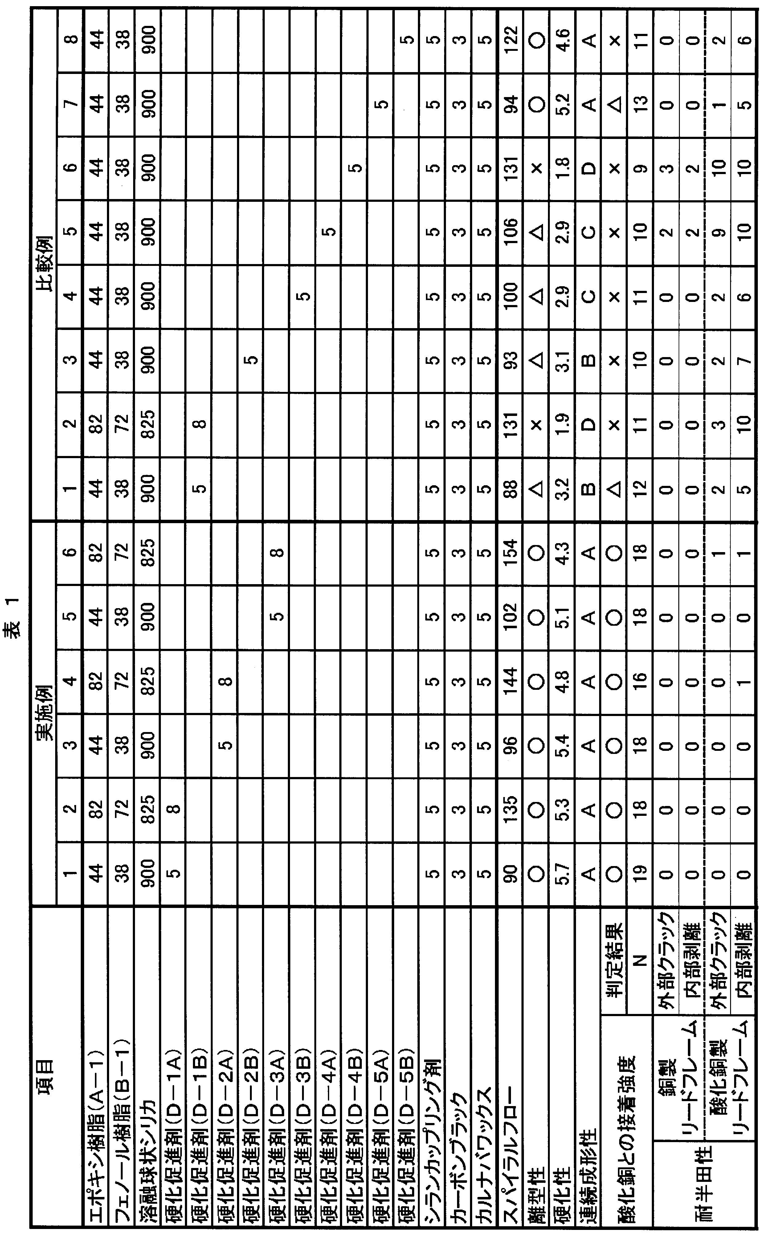
- the epoxy resin compositions of Examples 1 to 6 have extremely good fluidity (spiral flow), release properties, curability, and continuous moldability, and have high adhesive strength with copper oxide.
- the semiconductor device in which the silicon chip is sealed with a cured product of the object is not only when using a normal copper lead frame, but also when using a copper lead frame that has undergone oxidation, IR reflow treatment after humidification treatment As a result, excellent solder resistance was obtained.
- a highly reliable electronic component device having excellent solder resistance can be obtained. Therefore, it can be suitably used for electronic components such as ICs and LSIs, especially packages such as MCP (Multi Chip Stacked Package) in which chips are stacked in multiple stages, in which oxidation of a copper lead frame is likely to proceed.
- MCP Multi Chip Stacked Package
Landscapes
- Chemical & Material Sciences (AREA)
- Health & Medical Sciences (AREA)
- Chemical Kinetics & Catalysis (AREA)
- Medicinal Chemistry (AREA)
- Polymers & Plastics (AREA)
- Organic Chemistry (AREA)
- Epoxy Resins (AREA)
- Structures Or Materials For Encapsulating Or Coating Semiconductor Devices Or Solid State Devices (AREA)
- Compositions Of Macromolecular Compounds (AREA)
Abstract
Description
本願は、2011年1月28日に日本に出願された特願2011-016384号に基づき優先権を主張し、その内容をここに援用する。
前記(D)硬化促進剤が、平均粒径が10μm以下であり、かつ粒径20μmを超える粒子の割合が1質量%以下であり、
前記(D)硬化促進剤が、
下記一般式(1):
で表される化合物、
下記一般式(2):

で表される化合物及び
下記一般式(3):

で表される化合物からなる群から選ばれる少なくとも1種の硬化促進剤を含むことを特徴とする。
<測定実験>
大気下で220℃、120秒、加熱処理することにより、表面の酸化を進行させた酸化銅基材とタブレット化した前記エポキシ樹脂組成物を175℃、6.9MPa、2分の条件で一体成形して、酸化銅基材(直径3.6mm、厚さ0.5mm)上に円錐台状の成形品(上径3mm×下径3.6mm×厚さ3mm、酸化銅基材と樹脂硬化物の接触面積10mm2)を得た後、前記エポキシ樹脂組成物の硬化部位を横方向から押し、そのトルク(N)を測定する。
尚、各硬化促進剤の平均粒径、最大粒径及び粒径20μmを超える粒子の割合は、レーザー式粒度分布計((株)島津製作所製、SALD-7000)により測定した。
硬化促進剤(D-1A):硬化促進剤(D-1B)を、空気圧0.6MPa、原料供給速度3kg/hの条件でジェットミル(日本ニューマチック(株)製、PJM200SP)を用いて微粉砕することによって得た。得られた硬化促進剤(D-1A)は、平均粒径が3μm、最大粒径が24μm、粒径20μmを超える粒子の割合が0.5質量%であった。
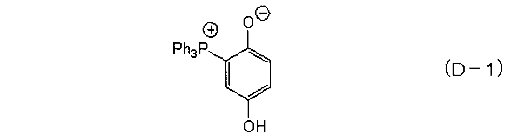
硬化促進剤(D-2A):硬化促進剤(D-2B)を、空気圧0.6MPa、原料供給速度3kg/hの条件でジェットミル(日本ニューマチック(株)製、PJM200SP)を用いて微粉砕することによって得た。得られた硬化促進剤(D-2A)は、平均粒径が4μm、最大粒径が24μm、粒径20μmを超える粒子の割合が0.8質量%であった。
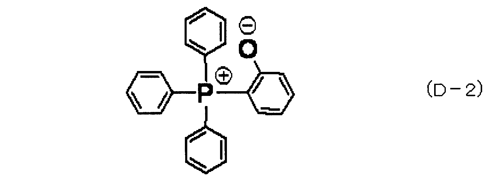
硬化促進剤(D-3A):硬化促進剤(D-3B)を、回転数60rpm、粉砕時間60分の条件でポットミル((株)森田鉄工製、ポットミルII型)を用いて微粉砕することによって得た。得られた硬化促進剤(D-3A)は、平均粒径が8μm、最大粒径が27μm、粒径20μmを超える粒子の割合が0.6質量%であった。
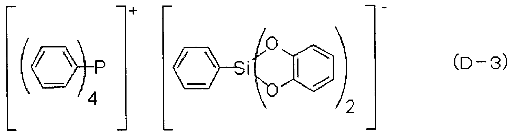
硬化促進剤(D-4A):硬化促進剤(D-4B)を、空気圧0.6MPa、原料供給速度3kg/hの条件でジェットミル(日本ニューマチック(株)製、PJM200SP)を用いて微粉砕することによって得た。得られた硬化促進剤(D-4A)は、平均粒径が5μm、最大粒径が24μm、粒径20μmを超える粒子の割合が0.7質量%であった。

硬化促進剤(D-5A):硬化促進剤(D-5B)を、空気圧0.6MPa、原料供給速度3kg/hの条件でジェットミル(日本ニューマチック(株)製、PJM200SP)を用いて微粉砕することによって得た。得られた硬化促進剤(D-5A)は、平均粒径が3μm、最大粒径が24μm、粒径20μmを超える粒子の割合が0.4質量%であった。

エポキシ樹脂(A-1):三菱化学(株)製、YX-4000(エポキシ当量190g/eq、融点105℃) 44質量部
フェノール樹脂(B-1):三井化学(株)製、XL-225(水酸基当量165g/eq、軟化点75℃) 38質量部
溶融球状シリカ(平均粒径24μm) 900質量部
硬化促進剤(D-1A) 5質量部
シランカップリング剤:γ-グリシドキシプロピルトリメトキシシラン(信越化学工業(株)製、KBM-403) 5質量部
カーボンブラック(三菱化学(株)製、♯5) 3質量部
カルナバワックス(日興ファイン(株)製、ニッコウカルナバ) 5質量部
をミキサーで混合し、熱ロールを用いて、95℃で8分間混練して冷却後粉砕し、エポキシ樹脂組成物を得た。得られたエポキシ樹脂組成物を、以下の方法で評価した。結果を表1に示す。
スパイラルフロー:低圧トランスファー成形機(コータキ精機(株)製、KTS-15)を用いて、ANSI/ASTM D 3123-72に準じたスパイラルフロー測定用の金型に、金型温度175℃、注入圧力6.9MPa、硬化時間120秒の条件でエポキシ樹脂組成物を注入し、流動長を測定した。スパイラルフローは、流動性のパラメータであり、数値が大きい方が流動性が良好である。単位はcm。
A:400ショットまで問題なし
B:300ショットまでにエアベントブロック発生
C:200ショットまでにエアベントブロック発生
D:100ショットまでにエアベントブロック発生
実施例2~6及び比較例1~8について、表1の配合に従い、実施例1と同様にして、エポキシ樹脂組成物を調製し評価した。結果を表1に示す。
2 ダイアタッチ材
3 支持部材(ダイパッド)
4 ボンディングワイヤ
5 リード
6 封止樹脂(エポキシ樹脂組成物)
8 電極パッド
9 インナーリード
Claims (9)
- (A)エポキシ樹脂、(B)フェノール樹脂系硬化剤、(C)無機充填材及び(D)硬化促進剤を含む封止用エポキシ樹脂組成物であって、
前記(D)硬化促進剤が、平均粒径が10μm以下であり、かつ粒径20μmを超える粒子の割合が1質量%以下であり、
前記(D)硬化促進剤が、
下記一般式(1):

で表される化合物、
下記一般式(2):

で表される化合物及び
下記一般式(3):

で表される化合物からなる群から選ばれる少なくとも1種の硬化促進剤を含むことを特徴とする封止用エポキシ樹脂組成物。 - 下記の測定実験における酸化銅との接着強度が14N以上である、請求項1記載の封止用エポキシ樹脂組成物。
<測定実験>
大気下で220℃、120秒、加熱処理することにより、表面の酸化を進行させた酸化銅基材とタブレット化した前記エポキシ樹脂組成物を175℃、6.9MPa、2分の条件で一体成形して、酸化銅基材(直径3.6mm、厚さ0.5mm)上に円錐台状の成形品(上径3mm×下径3.6mm×厚さ3mm、酸化銅基材と樹脂硬化物の接触面積10mm2)を得た後、前記エポキシ樹脂組成物の硬化部位を横方向から押し、そのトルク(N)を測定する。 - 前記封止用エポキシ樹脂組成物が銅表面または酸化銅表面に適用するためのものである請求項1または2に記載の封止用エポキシ樹脂組成物。
- 前記(C)無機充填材が、平均粒径10~30μmの溶融球状シリカを含むことを特徴とする請求項1ないし3のいずれか1項に記載の封止用エポキシ樹脂組成物。
- 前記溶融球状シリカが全樹脂組成物中に82質量%以上、92質量%以下の割合で含まれることを特徴とする請求項1ないし4のいずれか1項に記載の封止用エポキシ樹脂組成物。
- 前記(A)エポキシ樹脂が二官能の結晶性エポキシ樹脂を含むものである、請求項1ないし5のいずれか1項に記載の封止用エポキシ樹脂組成物。
- 請求項1から6のいずれか1項に記載の封止用エポキシ樹脂組成物の硬化物により電子部品が封止されていることを特徴とする電子部品装置。
- 前記電子部品が銅製リードフレームのダイパッド上に搭載され、前記電子部品の電極パッドと前記銅製リードフレームのインナーリードとがボンディングワイヤによって接続されていることを特徴とする請求項7記載の電子部品装置。
- 前記銅製リードフレームのダイパッド上に2以上の前記電子部品が積層して搭載されていることを特徴とする請求項8記載の電子部品装置。
Priority Applications (5)
| Application Number | Priority Date | Filing Date | Title |
|---|---|---|---|
| CN201280006193.0A CN103328531B (zh) | 2011-01-28 | 2012-01-26 | 密封用环氧树脂组合物和电子部件装置 |
| KR1020137019056A KR101847673B1 (ko) | 2011-01-28 | 2012-01-26 | 밀봉용 에폭시 수지 조성물 및 전자 부품 장치 |
| US13/976,538 US8987355B2 (en) | 2011-01-28 | 2012-01-26 | Epoxy resin composition for sealing, and electronic component device |
| SG2013049242A SG191755A1 (en) | 2011-01-28 | 2012-01-26 | Epoxy resin composition for sealing, and electronic component device |
| JP2012554832A JP6231277B2 (ja) | 2011-01-28 | 2012-01-26 | 封止用エポキシ樹脂組成物及び電子部品装置 |
Applications Claiming Priority (2)
| Application Number | Priority Date | Filing Date | Title |
|---|---|---|---|
| JP2011016384 | 2011-01-28 | ||
| JP2011-016384 | 2011-01-28 |
Publications (1)
| Publication Number | Publication Date |
|---|---|
| WO2012102336A1 true WO2012102336A1 (ja) | 2012-08-02 |
Family
ID=46580900
Family Applications (1)
| Application Number | Title | Priority Date | Filing Date |
|---|---|---|---|
| PCT/JP2012/051648 Ceased WO2012102336A1 (ja) | 2011-01-28 | 2012-01-26 | 封止用エポキシ樹脂組成物及び電子部品装置 |
Country Status (8)
| Country | Link |
|---|---|
| US (1) | US8987355B2 (ja) |
| JP (1) | JP6231277B2 (ja) |
| KR (1) | KR101847673B1 (ja) |
| CN (1) | CN103328531B (ja) |
| MY (1) | MY161145A (ja) |
| SG (1) | SG191755A1 (ja) |
| TW (1) | TWI530525B (ja) |
| WO (1) | WO2012102336A1 (ja) |
Cited By (3)
| Publication number | Priority date | Publication date | Assignee | Title |
|---|---|---|---|---|
| CN103972182A (zh) * | 2013-01-29 | 2014-08-06 | 富士电机株式会社 | 半导体装置及其制造方法以及粘接面强度的评估方法 |
| JP2016009814A (ja) * | 2014-06-26 | 2016-01-18 | 京セラケミカル株式会社 | 半導体封止用樹脂シート及び樹脂封止型半導体装置 |
| KR20240162491A (ko) | 2022-03-25 | 2024-11-15 | 파나소닉 아이피 매니지먼트 가부시키가이샤 | 봉지용 에폭시 수지 조성물, 및 전자 디바이스 |
Families Citing this family (12)
| Publication number | Priority date | Publication date | Assignee | Title |
|---|---|---|---|---|
| US20150357280A1 (en) * | 2014-06-06 | 2015-12-10 | Kabushiki Kaisha Toshiba | Memory card and method for manufacturing the same |
| JP6403075B2 (ja) * | 2014-11-26 | 2018-10-10 | 京セラ株式会社 | 半導体封止用樹脂組成物および半導体装置 |
| DE102015223467A1 (de) * | 2015-11-26 | 2017-06-01 | Robert Bosch Gmbh | Elektrische Vorrichtung mit einer Umhüllmasse |
| WO2017145411A1 (ja) * | 2016-02-25 | 2017-08-31 | 日立化成株式会社 | エポキシ樹脂成形材料、成形物、成形硬化物、及び成形硬化物の製造方法 |
| JP6980986B2 (ja) * | 2016-04-22 | 2021-12-15 | 住友ベークライト株式会社 | 半導体封止用樹脂組成物および半導体装置 |
| EP3460005B1 (en) * | 2016-05-18 | 2022-05-11 | Sumitomo Bakelite Co.Ltd. | Thermosetting resin composition for lds, resin molded article and three-dimensional molded circuit component |
| WO2018225599A1 (ja) | 2017-06-09 | 2018-12-13 | ナガセケムテックス株式会社 | エポキシ樹脂組成物、電子部品実装構造体およびその製造方法 |
| JPWO2020065873A1 (ja) * | 2018-09-27 | 2021-08-30 | 昭和電工マテリアルズ株式会社 | 封止用樹脂組成物、電子部品装置及び電子部品装置の製造方法 |
| CN111825947B (zh) * | 2019-04-22 | 2021-08-27 | 广东生益科技股份有限公司 | 一种用于金属基板的树脂组合物、包含其的树脂胶液以及金属基覆铜箔层压板 |
| US10950519B2 (en) | 2019-05-31 | 2021-03-16 | Taiwan Semiconductor Manufacturing Company, Ltd. | Integrated circuit package and method |
| JP7146719B2 (ja) * | 2019-10-31 | 2022-10-04 | タツタ電線株式会社 | 半導体装置 |
| CN115785400B (zh) * | 2021-09-10 | 2025-07-04 | 中国科学院化学研究所 | 一种能够降低环氧树脂固化应力的潜伏性促进剂及其制备方法与应用 |
Citations (8)
| Publication number | Priority date | Publication date | Assignee | Title |
|---|---|---|---|---|
| JPS6259626A (ja) * | 1985-09-10 | 1987-03-16 | Shin Etsu Chem Co Ltd | エポキシ樹脂組成物 |
| JP2006169407A (ja) * | 2004-12-16 | 2006-06-29 | Nitto Denko Corp | 半導体封止用樹脂組成物 |
| JP2006225630A (ja) * | 2005-01-20 | 2006-08-31 | Sumitomo Bakelite Co Ltd | エポキシ樹脂組成物、その潜伏化手法および半導体装置 |
| JP2006299246A (ja) * | 2005-03-24 | 2006-11-02 | Shin Etsu Chem Co Ltd | 半導体封止用エポキシ樹脂組成物及び半導体装置 |
| JP2008231242A (ja) * | 2007-03-20 | 2008-10-02 | Sumitomo Bakelite Co Ltd | エポキシ樹脂組成物及び半導体装置 |
| WO2010140331A1 (ja) * | 2009-06-03 | 2010-12-09 | 住友ベークライト株式会社 | 半導体封止用樹脂組成物及び半導体装置 |
| JP2011252086A (ja) * | 2010-06-02 | 2011-12-15 | Sumitomo Bakelite Co Ltd | 樹脂成形体及びその製造方法、ならびに、電子部品装置 |
| WO2012029762A1 (ja) * | 2010-09-02 | 2012-03-08 | 住友ベークライト株式会社 | 樹脂成形体及びその製造方法、樹脂組成物及びその製造方法ならびに、電子部品装置 |
Family Cites Families (11)
| Publication number | Priority date | Publication date | Assignee | Title |
|---|---|---|---|---|
| JPS6134019A (ja) * | 1984-07-25 | 1986-02-18 | Matsushita Electric Works Ltd | 封止用樹脂組成物の製法 |
| JP2576713B2 (ja) * | 1991-04-24 | 1997-01-29 | 信越化学工業株式会社 | エポキシ樹脂組成物及び半導体装置 |
| JP4742435B2 (ja) * | 2001-03-28 | 2011-08-10 | 住友ベークライト株式会社 | エポキシ樹脂組成物及び半導体装置 |
| JP4424595B2 (ja) * | 2004-05-06 | 2010-03-03 | 日東電工株式会社 | 半導体封止用樹脂組成物 |
| KR101250033B1 (ko) * | 2005-01-20 | 2013-04-02 | 스미토모 베이클리트 컴퍼니 리미티드 | 에폭시 수지 조성물, 그 잠복화 방법 및 반도체 장치 |
| JP2007262238A (ja) * | 2006-03-28 | 2007-10-11 | Sumitomo Bakelite Co Ltd | エポキシ樹脂用硬化剤組成物及びそれを用いたエポキシ樹脂組成物並びに半導体装置 |
| WO2007125635A1 (ja) * | 2006-03-31 | 2007-11-08 | Sumitomo Bakelite Co., Ltd. | 半導体封止用樹脂組成物及び半導体装置 |
| JP2008031326A (ja) * | 2006-07-31 | 2008-02-14 | Sumitomo Bakelite Co Ltd | 半導体封止用エポキシ樹脂組成物及び半導体装置 |
| JP5141124B2 (ja) * | 2006-08-07 | 2013-02-13 | 住友ベークライト株式会社 | 半導体封止用エポキシ樹脂組成物及び半導体装置 |
| JP5141125B2 (ja) * | 2006-09-28 | 2013-02-13 | 住友ベークライト株式会社 | 半導体封止用エポキシ樹脂組成物及び半導体装置 |
| JP5340558B2 (ja) | 2007-05-17 | 2013-11-13 | 日東電工株式会社 | 半導体封止用エポキシ樹脂組成物およびそれを用いて得られる半導体装置 |
-
2012
- 2012-01-26 KR KR1020137019056A patent/KR101847673B1/ko not_active Expired - Fee Related
- 2012-01-26 WO PCT/JP2012/051648 patent/WO2012102336A1/ja not_active Ceased
- 2012-01-26 US US13/976,538 patent/US8987355B2/en not_active Expired - Fee Related
- 2012-01-26 MY MYPI2013002556A patent/MY161145A/en unknown
- 2012-01-26 CN CN201280006193.0A patent/CN103328531B/zh active Active
- 2012-01-26 SG SG2013049242A patent/SG191755A1/en unknown
- 2012-01-26 JP JP2012554832A patent/JP6231277B2/ja active Active
- 2012-01-30 TW TW101102792A patent/TWI530525B/zh not_active IP Right Cessation
Patent Citations (8)
| Publication number | Priority date | Publication date | Assignee | Title |
|---|---|---|---|---|
| JPS6259626A (ja) * | 1985-09-10 | 1987-03-16 | Shin Etsu Chem Co Ltd | エポキシ樹脂組成物 |
| JP2006169407A (ja) * | 2004-12-16 | 2006-06-29 | Nitto Denko Corp | 半導体封止用樹脂組成物 |
| JP2006225630A (ja) * | 2005-01-20 | 2006-08-31 | Sumitomo Bakelite Co Ltd | エポキシ樹脂組成物、その潜伏化手法および半導体装置 |
| JP2006299246A (ja) * | 2005-03-24 | 2006-11-02 | Shin Etsu Chem Co Ltd | 半導体封止用エポキシ樹脂組成物及び半導体装置 |
| JP2008231242A (ja) * | 2007-03-20 | 2008-10-02 | Sumitomo Bakelite Co Ltd | エポキシ樹脂組成物及び半導体装置 |
| WO2010140331A1 (ja) * | 2009-06-03 | 2010-12-09 | 住友ベークライト株式会社 | 半導体封止用樹脂組成物及び半導体装置 |
| JP2011252086A (ja) * | 2010-06-02 | 2011-12-15 | Sumitomo Bakelite Co Ltd | 樹脂成形体及びその製造方法、ならびに、電子部品装置 |
| WO2012029762A1 (ja) * | 2010-09-02 | 2012-03-08 | 住友ベークライト株式会社 | 樹脂成形体及びその製造方法、樹脂組成物及びその製造方法ならびに、電子部品装置 |
Cited By (4)
| Publication number | Priority date | Publication date | Assignee | Title |
|---|---|---|---|---|
| CN103972182A (zh) * | 2013-01-29 | 2014-08-06 | 富士电机株式会社 | 半导体装置及其制造方法以及粘接面强度的评估方法 |
| JP2014146704A (ja) * | 2013-01-29 | 2014-08-14 | Fuji Electric Co Ltd | 半導体装置 |
| JP2016009814A (ja) * | 2014-06-26 | 2016-01-18 | 京セラケミカル株式会社 | 半導体封止用樹脂シート及び樹脂封止型半導体装置 |
| KR20240162491A (ko) | 2022-03-25 | 2024-11-15 | 파나소닉 아이피 매니지먼트 가부시키가이샤 | 봉지용 에폭시 수지 조성물, 및 전자 디바이스 |
Also Published As
| Publication number | Publication date |
|---|---|
| KR20140017526A (ko) | 2014-02-11 |
| JPWO2012102336A1 (ja) | 2014-06-30 |
| US20130277867A1 (en) | 2013-10-24 |
| KR101847673B1 (ko) | 2018-04-10 |
| MY161145A (en) | 2017-04-14 |
| JP6231277B2 (ja) | 2017-11-15 |
| CN103328531A (zh) | 2013-09-25 |
| US8987355B2 (en) | 2015-03-24 |
| TWI530525B (zh) | 2016-04-21 |
| SG191755A1 (en) | 2013-08-30 |
| TW201231546A (en) | 2012-08-01 |
| CN103328531B (zh) | 2017-05-17 |
Similar Documents
| Publication | Publication Date | Title |
|---|---|---|
| JP6231277B2 (ja) | 封止用エポキシ樹脂組成物及び電子部品装置 | |
| US7696286B2 (en) | Semiconductor encapsulant of epoxy resin, polyphenolic compound, filler and accelerator | |
| JP5874633B2 (ja) | 半導体封止用エポキシ樹脂組成物の製造方法およびこれを用いる半導体装置の製造方法 | |
| JP6551499B2 (ja) | コンプレッション成形用半導体封止樹脂材料及び半導体装置 | |
| JP7571814B2 (ja) | エポキシ樹脂組成物、及び電子部品装置 | |
| CN116751438A (zh) | 环氧树脂组合物和电子部件装置 | |
| JP2024096265A (ja) | 樹脂組成物及び電子部品装置 | |
| JP5228496B2 (ja) | 半導体封止用エポキシ樹脂組成物及び半導体装置 | |
| JP6171274B2 (ja) | 封止用エポキシ樹脂成形材料及び電子部品装置 | |
| JP2008266610A (ja) | 半導体封止用樹脂組成物及び半導体装置 | |
| JP5272973B2 (ja) | エポキシ樹脂組成物及び半導体装置 | |
| JP5386837B2 (ja) | 半導体封止用樹脂組成物及び半導体装置 | |
| JP5200867B2 (ja) | 半導体封止用エポキシ樹脂組成物及び半導体装置 | |
| JP2012007086A (ja) | 封止用樹脂組成物及び電子部品装置 | |
| JP6372967B2 (ja) | 封止用エポキシ樹脂成形材料及び電子部品装置 | |
| JP5029133B2 (ja) | 半導体封止用エポキシ樹脂組成物及び半導体装置 | |
| JP5087860B2 (ja) | 半導体封止用エポキシ樹脂組成物及び半導体装置 | |
| JP5092676B2 (ja) | エポキシ樹脂組成物及び半導体装置 | |
| JP2017106034A (ja) | 封止用エポキシ樹脂成形材料及び電子部品装置 | |
| JP2013006943A (ja) | 封止用樹脂組成物及び電子部品装置 | |
| JP2013006934A (ja) | 封止用樹脂組成物及び電子部品装置 | |
| JP5092675B2 (ja) | エポキシ樹脂組成物及び半導体装置 | |
| JP2006291038A (ja) | 封止用エポキシ樹脂成形材料及び電子部品装置 | |
| JP2012255132A (ja) | 封止用エポキシ樹脂成形材料及び電子部品装置 | |
| JP2024076902A (ja) | 構造体、電子部品装置及び構造体の製造方法 |
Legal Events
| Date | Code | Title | Description |
|---|---|---|---|
| 121 | Ep: the epo has been informed by wipo that ep was designated in this application |
Ref document number: 12738912 Country of ref document: EP Kind code of ref document: A1 |
|
| ENP | Entry into the national phase |
Ref document number: 2012554832 Country of ref document: JP Kind code of ref document: A |
|
| WWE | Wipo information: entry into national phase |
Ref document number: 13976538 Country of ref document: US |
|
| ENP | Entry into the national phase |
Ref document number: 20137019056 Country of ref document: KR Kind code of ref document: A |
|
| WWE | Wipo information: entry into national phase |
Ref document number: 1301004058 Country of ref document: TH |
|
| NENP | Non-entry into the national phase |
Ref country code: DE |
|
| 122 | Ep: pct application non-entry in european phase |
Ref document number: 12738912 Country of ref document: EP Kind code of ref document: A1 |