WO2012102123A1 - ハイブリッド車両の制御装置および制御方法 - Google Patents
ハイブリッド車両の制御装置および制御方法 Download PDFInfo
- Publication number
- WO2012102123A1 WO2012102123A1 PCT/JP2012/050785 JP2012050785W WO2012102123A1 WO 2012102123 A1 WO2012102123 A1 WO 2012102123A1 JP 2012050785 W JP2012050785 W JP 2012050785W WO 2012102123 A1 WO2012102123 A1 WO 2012102123A1
- Authority
- WO
- WIPO (PCT)
- Prior art keywords
- fuel
- fuel consumption
- deterioration
- hybrid vehicle
- engine
- Prior art date
- Legal status (The legal status is an assumption and is not a legal conclusion. Google has not performed a legal analysis and makes no representation as to the accuracy of the status listed.)
- Ceased
Links
Images




Classifications
-
- B—PERFORMING OPERATIONS; TRANSPORTING
- B60—VEHICLES IN GENERAL
- B60L—PROPULSION OF ELECTRICALLY-PROPELLED VEHICLES; SUPPLYING ELECTRIC POWER FOR AUXILIARY EQUIPMENT OF ELECTRICALLY-PROPELLED VEHICLES; ELECTRODYNAMIC BRAKE SYSTEMS FOR VEHICLES IN GENERAL; MAGNETIC SUSPENSION OR LEVITATION FOR VEHICLES; MONITORING OPERATING VARIABLES OF ELECTRICALLY-PROPELLED VEHICLES; ELECTRIC SAFETY DEVICES FOR ELECTRICALLY-PROPELLED VEHICLES
- B60L53/00—Methods of charging batteries, specially adapted for electric vehicles; Charging stations or on-board charging equipment therefor; Exchange of energy storage elements in electric vehicles
- B60L53/10—Methods of charging batteries, specially adapted for electric vehicles; Charging stations or on-board charging equipment therefor; Exchange of energy storage elements in electric vehicles characterised by the energy transfer between the charging station and the vehicle
- B60L53/14—Conductive energy transfer
-
- B—PERFORMING OPERATIONS; TRANSPORTING
- B60—VEHICLES IN GENERAL
- B60K—ARRANGEMENT OR MOUNTING OF PROPULSION UNITS OR OF TRANSMISSIONS IN VEHICLES; ARRANGEMENT OR MOUNTING OF PLURAL DIVERSE PRIME-MOVERS IN VEHICLES; AUXILIARY DRIVES FOR VEHICLES; INSTRUMENTATION OR DASHBOARDS FOR VEHICLES; ARRANGEMENTS IN CONNECTION WITH COOLING, AIR INTAKE, GAS EXHAUST OR FUEL SUPPLY OF PROPULSION UNITS IN VEHICLES
- B60K6/00—Arrangement or mounting of plural diverse prime-movers for mutual or common propulsion, e.g. hybrid propulsion systems comprising electric motors and internal combustion engines
- B60K6/20—Arrangement or mounting of plural diverse prime-movers for mutual or common propulsion, e.g. hybrid propulsion systems comprising electric motors and internal combustion engines the prime-movers consisting of electric motors and internal combustion engines, e.g. HEVs
- B60K6/42—Arrangement or mounting of plural diverse prime-movers for mutual or common propulsion, e.g. hybrid propulsion systems comprising electric motors and internal combustion engines the prime-movers consisting of electric motors and internal combustion engines, e.g. HEVs characterised by the architecture of the hybrid electric vehicle
- B60K6/46—Series type
-
- B—PERFORMING OPERATIONS; TRANSPORTING
- B60—VEHICLES IN GENERAL
- B60L—PROPULSION OF ELECTRICALLY-PROPELLED VEHICLES; SUPPLYING ELECTRIC POWER FOR AUXILIARY EQUIPMENT OF ELECTRICALLY-PROPELLED VEHICLES; ELECTRODYNAMIC BRAKE SYSTEMS FOR VEHICLES IN GENERAL; MAGNETIC SUSPENSION OR LEVITATION FOR VEHICLES; MONITORING OPERATING VARIABLES OF ELECTRICALLY-PROPELLED VEHICLES; ELECTRIC SAFETY DEVICES FOR ELECTRICALLY-PROPELLED VEHICLES
- B60L50/00—Electric propulsion with power supplied within the vehicle
- B60L50/40—Electric propulsion with power supplied within the vehicle using propulsion power supplied by capacitors
-
- B—PERFORMING OPERATIONS; TRANSPORTING
- B60—VEHICLES IN GENERAL
- B60L—PROPULSION OF ELECTRICALLY-PROPELLED VEHICLES; SUPPLYING ELECTRIC POWER FOR AUXILIARY EQUIPMENT OF ELECTRICALLY-PROPELLED VEHICLES; ELECTRODYNAMIC BRAKE SYSTEMS FOR VEHICLES IN GENERAL; MAGNETIC SUSPENSION OR LEVITATION FOR VEHICLES; MONITORING OPERATING VARIABLES OF ELECTRICALLY-PROPELLED VEHICLES; ELECTRIC SAFETY DEVICES FOR ELECTRICALLY-PROPELLED VEHICLES
- B60L50/00—Electric propulsion with power supplied within the vehicle
- B60L50/50—Electric propulsion with power supplied within the vehicle using propulsion power supplied by batteries or fuel cells
- B60L50/60—Electric propulsion with power supplied within the vehicle using propulsion power supplied by batteries or fuel cells using power supplied by batteries
- B60L50/61—Electric propulsion with power supplied within the vehicle using propulsion power supplied by batteries or fuel cells using power supplied by batteries by batteries charged by engine-driven generators, e.g. series hybrid electric vehicles
-
- B—PERFORMING OPERATIONS; TRANSPORTING
- B60—VEHICLES IN GENERAL
- B60L—PROPULSION OF ELECTRICALLY-PROPELLED VEHICLES; SUPPLYING ELECTRIC POWER FOR AUXILIARY EQUIPMENT OF ELECTRICALLY-PROPELLED VEHICLES; ELECTRODYNAMIC BRAKE SYSTEMS FOR VEHICLES IN GENERAL; MAGNETIC SUSPENSION OR LEVITATION FOR VEHICLES; MONITORING OPERATING VARIABLES OF ELECTRICALLY-PROPELLED VEHICLES; ELECTRIC SAFETY DEVICES FOR ELECTRICALLY-PROPELLED VEHICLES
- B60L58/00—Methods or circuit arrangements for monitoring or controlling batteries or fuel cells, specially adapted for electric vehicles
- B60L58/10—Methods or circuit arrangements for monitoring or controlling batteries or fuel cells, specially adapted for electric vehicles for monitoring or controlling batteries
- B60L58/12—Methods or circuit arrangements for monitoring or controlling batteries or fuel cells, specially adapted for electric vehicles for monitoring or controlling batteries responding to state of charge [SoC]
-
- B—PERFORMING OPERATIONS; TRANSPORTING
- B60—VEHICLES IN GENERAL
- B60L—PROPULSION OF ELECTRICALLY-PROPELLED VEHICLES; SUPPLYING ELECTRIC POWER FOR AUXILIARY EQUIPMENT OF ELECTRICALLY-PROPELLED VEHICLES; ELECTRODYNAMIC BRAKE SYSTEMS FOR VEHICLES IN GENERAL; MAGNETIC SUSPENSION OR LEVITATION FOR VEHICLES; MONITORING OPERATING VARIABLES OF ELECTRICALLY-PROPELLED VEHICLES; ELECTRIC SAFETY DEVICES FOR ELECTRICALLY-PROPELLED VEHICLES
- B60L7/00—Electrodynamic brake systems for vehicles in general
- B60L7/10—Dynamic electric regenerative braking
- B60L7/14—Dynamic electric regenerative braking for vehicles propelled by AC motors
-
- B—PERFORMING OPERATIONS; TRANSPORTING
- B60—VEHICLES IN GENERAL
- B60W—CONJOINT CONTROL OF VEHICLE SUB-UNITS OF DIFFERENT TYPE OR DIFFERENT FUNCTION; CONTROL SYSTEMS SPECIALLY ADAPTED FOR HYBRID VEHICLES; ROAD VEHICLE DRIVE CONTROL SYSTEMS FOR PURPOSES NOT RELATED TO THE CONTROL OF A PARTICULAR SUB-UNIT
- B60W10/00—Conjoint control of vehicle sub-units of different type or different function
- B60W10/04—Conjoint control of vehicle sub-units of different type or different function including control of propulsion units
- B60W10/06—Conjoint control of vehicle sub-units of different type or different function including control of propulsion units including control of combustion engines
-
- B—PERFORMING OPERATIONS; TRANSPORTING
- B60—VEHICLES IN GENERAL
- B60W—CONJOINT CONTROL OF VEHICLE SUB-UNITS OF DIFFERENT TYPE OR DIFFERENT FUNCTION; CONTROL SYSTEMS SPECIALLY ADAPTED FOR HYBRID VEHICLES; ROAD VEHICLE DRIVE CONTROL SYSTEMS FOR PURPOSES NOT RELATED TO THE CONTROL OF A PARTICULAR SUB-UNIT
- B60W10/00—Conjoint control of vehicle sub-units of different type or different function
- B60W10/24—Conjoint control of vehicle sub-units of different type or different function including control of energy storage means
- B60W10/26—Conjoint control of vehicle sub-units of different type or different function including control of energy storage means for electrical energy, e.g. batteries or capacitors
-
- B—PERFORMING OPERATIONS; TRANSPORTING
- B60—VEHICLES IN GENERAL
- B60W—CONJOINT CONTROL OF VEHICLE SUB-UNITS OF DIFFERENT TYPE OR DIFFERENT FUNCTION; CONTROL SYSTEMS SPECIALLY ADAPTED FOR HYBRID VEHICLES; ROAD VEHICLE DRIVE CONTROL SYSTEMS FOR PURPOSES NOT RELATED TO THE CONTROL OF A PARTICULAR SUB-UNIT
- B60W20/00—Control systems specially adapted for hybrid vehicles
-
- B—PERFORMING OPERATIONS; TRANSPORTING
- B60—VEHICLES IN GENERAL
- B60W—CONJOINT CONTROL OF VEHICLE SUB-UNITS OF DIFFERENT TYPE OR DIFFERENT FUNCTION; CONTROL SYSTEMS SPECIALLY ADAPTED FOR HYBRID VEHICLES; ROAD VEHICLE DRIVE CONTROL SYSTEMS FOR PURPOSES NOT RELATED TO THE CONTROL OF A PARTICULAR SUB-UNIT
- B60W20/00—Control systems specially adapted for hybrid vehicles
- B60W20/10—Controlling the power contribution of each of the prime movers to meet required power demand
- B60W20/15—Control strategies specially adapted for achieving a particular effect
-
- B—PERFORMING OPERATIONS; TRANSPORTING
- B60—VEHICLES IN GENERAL
- B60W—CONJOINT CONTROL OF VEHICLE SUB-UNITS OF DIFFERENT TYPE OR DIFFERENT FUNCTION; CONTROL SYSTEMS SPECIALLY ADAPTED FOR HYBRID VEHICLES; ROAD VEHICLE DRIVE CONTROL SYSTEMS FOR PURPOSES NOT RELATED TO THE CONTROL OF A PARTICULAR SUB-UNIT
- B60W20/00—Control systems specially adapted for hybrid vehicles
- B60W20/10—Controlling the power contribution of each of the prime movers to meet required power demand
- B60W20/15—Control strategies specially adapted for achieving a particular effect
- B60W20/18—Control strategies specially adapted for achieving a particular effect for avoiding ageing of fuel
-
- B—PERFORMING OPERATIONS; TRANSPORTING
- B60—VEHICLES IN GENERAL
- B60W—CONJOINT CONTROL OF VEHICLE SUB-UNITS OF DIFFERENT TYPE OR DIFFERENT FUNCTION; CONTROL SYSTEMS SPECIALLY ADAPTED FOR HYBRID VEHICLES; ROAD VEHICLE DRIVE CONTROL SYSTEMS FOR PURPOSES NOT RELATED TO THE CONTROL OF A PARTICULAR SUB-UNIT
- B60W40/00—Estimation or calculation of non-directly measurable driving parameters for road vehicle drive control systems not related to the control of a particular sub unit, e.g. by using mathematical models
-
- F—MECHANICAL ENGINEERING; LIGHTING; HEATING; WEAPONS; BLASTING
- F02—COMBUSTION ENGINES; HOT-GAS OR COMBUSTION-PRODUCT ENGINE PLANTS
- F02N—STARTING OF COMBUSTION ENGINES; STARTING AIDS FOR SUCH ENGINES, NOT OTHERWISE PROVIDED FOR
- F02N11/00—Starting of engines by means of electric motors
- F02N11/08—Circuits specially adapted for starting of engines
- F02N11/0814—Circuits specially adapted for starting of engines comprising means for controlling automatic idle-start-stop
- F02N11/0818—Conditions for starting or stopping the engine or for deactivating the idle-start-stop mode
-
- B—PERFORMING OPERATIONS; TRANSPORTING
- B60—VEHICLES IN GENERAL
- B60L—PROPULSION OF ELECTRICALLY-PROPELLED VEHICLES; SUPPLYING ELECTRIC POWER FOR AUXILIARY EQUIPMENT OF ELECTRICALLY-PROPELLED VEHICLES; ELECTRODYNAMIC BRAKE SYSTEMS FOR VEHICLES IN GENERAL; MAGNETIC SUSPENSION OR LEVITATION FOR VEHICLES; MONITORING OPERATING VARIABLES OF ELECTRICALLY-PROPELLED VEHICLES; ELECTRIC SAFETY DEVICES FOR ELECTRICALLY-PROPELLED VEHICLES
- B60L2210/00—Converter types
- B60L2210/30—AC to DC converters
-
- B—PERFORMING OPERATIONS; TRANSPORTING
- B60—VEHICLES IN GENERAL
- B60L—PROPULSION OF ELECTRICALLY-PROPELLED VEHICLES; SUPPLYING ELECTRIC POWER FOR AUXILIARY EQUIPMENT OF ELECTRICALLY-PROPELLED VEHICLES; ELECTRODYNAMIC BRAKE SYSTEMS FOR VEHICLES IN GENERAL; MAGNETIC SUSPENSION OR LEVITATION FOR VEHICLES; MONITORING OPERATING VARIABLES OF ELECTRICALLY-PROPELLED VEHICLES; ELECTRIC SAFETY DEVICES FOR ELECTRICALLY-PROPELLED VEHICLES
- B60L2210/00—Converter types
- B60L2210/40—DC to AC converters
-
- B—PERFORMING OPERATIONS; TRANSPORTING
- B60—VEHICLES IN GENERAL
- B60L—PROPULSION OF ELECTRICALLY-PROPELLED VEHICLES; SUPPLYING ELECTRIC POWER FOR AUXILIARY EQUIPMENT OF ELECTRICALLY-PROPELLED VEHICLES; ELECTRODYNAMIC BRAKE SYSTEMS FOR VEHICLES IN GENERAL; MAGNETIC SUSPENSION OR LEVITATION FOR VEHICLES; MONITORING OPERATING VARIABLES OF ELECTRICALLY-PROPELLED VEHICLES; ELECTRIC SAFETY DEVICES FOR ELECTRICALLY-PROPELLED VEHICLES
- B60L2240/00—Control parameters of input or output; Target parameters
- B60L2240/40—Drive Train control parameters
- B60L2240/46—Drive Train control parameters related to wheels
- B60L2240/461—Speed
-
- B—PERFORMING OPERATIONS; TRANSPORTING
- B60—VEHICLES IN GENERAL
- B60W—CONJOINT CONTROL OF VEHICLE SUB-UNITS OF DIFFERENT TYPE OR DIFFERENT FUNCTION; CONTROL SYSTEMS SPECIALLY ADAPTED FOR HYBRID VEHICLES; ROAD VEHICLE DRIVE CONTROL SYSTEMS FOR PURPOSES NOT RELATED TO THE CONTROL OF A PARTICULAR SUB-UNIT
- B60W2510/00—Input parameters relating to a particular sub-units
- B60W2510/06—Combustion engines, Gas turbines
- B60W2510/0614—Position of fuel or air injector
- B60W2510/0623—Fuel flow rate
-
- F—MECHANICAL ENGINEERING; LIGHTING; HEATING; WEAPONS; BLASTING
- F02—COMBUSTION ENGINES; HOT-GAS OR COMBUSTION-PRODUCT ENGINE PLANTS
- F02D—CONTROLLING COMBUSTION ENGINES
- F02D2200/00—Input parameters for engine control
- F02D2200/02—Input parameters for engine control the parameters being related to the engine
- F02D2200/06—Fuel or fuel supply system parameters
- F02D2200/0625—Fuel consumption, e.g. measured in fuel liters per 100 kms or miles per gallon
-
- F—MECHANICAL ENGINEERING; LIGHTING; HEATING; WEAPONS; BLASTING
- F02—COMBUSTION ENGINES; HOT-GAS OR COMBUSTION-PRODUCT ENGINE PLANTS
- F02D—CONTROLLING COMBUSTION ENGINES
- F02D41/00—Electrical control of supply of combustible mixture or its constituents
-
- F—MECHANICAL ENGINEERING; LIGHTING; HEATING; WEAPONS; BLASTING
- F02—COMBUSTION ENGINES; HOT-GAS OR COMBUSTION-PRODUCT ENGINE PLANTS
- F02D—CONTROLLING COMBUSTION ENGINES
- F02D41/00—Electrical control of supply of combustible mixture or its constituents
- F02D41/02—Circuit arrangements for generating control signals
- F02D41/021—Introducing corrections for particular conditions exterior to the engine
-
- Y—GENERAL TAGGING OF NEW TECHNOLOGICAL DEVELOPMENTS; GENERAL TAGGING OF CROSS-SECTIONAL TECHNOLOGIES SPANNING OVER SEVERAL SECTIONS OF THE IPC; TECHNICAL SUBJECTS COVERED BY FORMER USPC CROSS-REFERENCE ART COLLECTIONS [XRACs] AND DIGESTS
- Y02—TECHNOLOGIES OR APPLICATIONS FOR MITIGATION OR ADAPTATION AGAINST CLIMATE CHANGE
- Y02T—CLIMATE CHANGE MITIGATION TECHNOLOGIES RELATED TO TRANSPORTATION
- Y02T10/00—Road transport of goods or passengers
- Y02T10/10—Internal combustion engine [ICE] based vehicles
- Y02T10/40—Engine management systems
-
- Y—GENERAL TAGGING OF NEW TECHNOLOGICAL DEVELOPMENTS; GENERAL TAGGING OF CROSS-SECTIONAL TECHNOLOGIES SPANNING OVER SEVERAL SECTIONS OF THE IPC; TECHNICAL SUBJECTS COVERED BY FORMER USPC CROSS-REFERENCE ART COLLECTIONS [XRACs] AND DIGESTS
- Y02—TECHNOLOGIES OR APPLICATIONS FOR MITIGATION OR ADAPTATION AGAINST CLIMATE CHANGE
- Y02T—CLIMATE CHANGE MITIGATION TECHNOLOGIES RELATED TO TRANSPORTATION
- Y02T10/00—Road transport of goods or passengers
- Y02T10/60—Other road transportation technologies with climate change mitigation effect
- Y02T10/62—Hybrid vehicles
-
- Y—GENERAL TAGGING OF NEW TECHNOLOGICAL DEVELOPMENTS; GENERAL TAGGING OF CROSS-SECTIONAL TECHNOLOGIES SPANNING OVER SEVERAL SECTIONS OF THE IPC; TECHNICAL SUBJECTS COVERED BY FORMER USPC CROSS-REFERENCE ART COLLECTIONS [XRACs] AND DIGESTS
- Y02—TECHNOLOGIES OR APPLICATIONS FOR MITIGATION OR ADAPTATION AGAINST CLIMATE CHANGE
- Y02T—CLIMATE CHANGE MITIGATION TECHNOLOGIES RELATED TO TRANSPORTATION
- Y02T10/00—Road transport of goods or passengers
- Y02T10/60—Other road transportation technologies with climate change mitigation effect
- Y02T10/70—Energy storage systems for electromobility, e.g. batteries
-
- Y—GENERAL TAGGING OF NEW TECHNOLOGICAL DEVELOPMENTS; GENERAL TAGGING OF CROSS-SECTIONAL TECHNOLOGIES SPANNING OVER SEVERAL SECTIONS OF THE IPC; TECHNICAL SUBJECTS COVERED BY FORMER USPC CROSS-REFERENCE ART COLLECTIONS [XRACs] AND DIGESTS
- Y02—TECHNOLOGIES OR APPLICATIONS FOR MITIGATION OR ADAPTATION AGAINST CLIMATE CHANGE
- Y02T—CLIMATE CHANGE MITIGATION TECHNOLOGIES RELATED TO TRANSPORTATION
- Y02T10/00—Road transport of goods or passengers
- Y02T10/60—Other road transportation technologies with climate change mitigation effect
- Y02T10/7072—Electromobility specific charging systems or methods for batteries, ultracapacitors, supercapacitors or double-layer capacitors
-
- Y—GENERAL TAGGING OF NEW TECHNOLOGICAL DEVELOPMENTS; GENERAL TAGGING OF CROSS-SECTIONAL TECHNOLOGIES SPANNING OVER SEVERAL SECTIONS OF THE IPC; TECHNICAL SUBJECTS COVERED BY FORMER USPC CROSS-REFERENCE ART COLLECTIONS [XRACs] AND DIGESTS
- Y02—TECHNOLOGIES OR APPLICATIONS FOR MITIGATION OR ADAPTATION AGAINST CLIMATE CHANGE
- Y02T—CLIMATE CHANGE MITIGATION TECHNOLOGIES RELATED TO TRANSPORTATION
- Y02T10/00—Road transport of goods or passengers
- Y02T10/60—Other road transportation technologies with climate change mitigation effect
- Y02T10/72—Electric energy management in electromobility
-
- Y—GENERAL TAGGING OF NEW TECHNOLOGICAL DEVELOPMENTS; GENERAL TAGGING OF CROSS-SECTIONAL TECHNOLOGIES SPANNING OVER SEVERAL SECTIONS OF THE IPC; TECHNICAL SUBJECTS COVERED BY FORMER USPC CROSS-REFERENCE ART COLLECTIONS [XRACs] AND DIGESTS
- Y02—TECHNOLOGIES OR APPLICATIONS FOR MITIGATION OR ADAPTATION AGAINST CLIMATE CHANGE
- Y02T—CLIMATE CHANGE MITIGATION TECHNOLOGIES RELATED TO TRANSPORTATION
- Y02T10/00—Road transport of goods or passengers
- Y02T10/80—Technologies aiming to reduce greenhouse gasses emissions common to all road transportation technologies
- Y02T10/84—Data processing systems or methods, management, administration
-
- Y—GENERAL TAGGING OF NEW TECHNOLOGICAL DEVELOPMENTS; GENERAL TAGGING OF CROSS-SECTIONAL TECHNOLOGIES SPANNING OVER SEVERAL SECTIONS OF THE IPC; TECHNICAL SUBJECTS COVERED BY FORMER USPC CROSS-REFERENCE ART COLLECTIONS [XRACs] AND DIGESTS
- Y02—TECHNOLOGIES OR APPLICATIONS FOR MITIGATION OR ADAPTATION AGAINST CLIMATE CHANGE
- Y02T—CLIMATE CHANGE MITIGATION TECHNOLOGIES RELATED TO TRANSPORTATION
- Y02T90/00—Enabling technologies or technologies with a potential or indirect contribution to GHG emissions mitigation
- Y02T90/10—Technologies relating to charging of electric vehicles
- Y02T90/12—Electric charging stations
-
- Y—GENERAL TAGGING OF NEW TECHNOLOGICAL DEVELOPMENTS; GENERAL TAGGING OF CROSS-SECTIONAL TECHNOLOGIES SPANNING OVER SEVERAL SECTIONS OF THE IPC; TECHNICAL SUBJECTS COVERED BY FORMER USPC CROSS-REFERENCE ART COLLECTIONS [XRACs] AND DIGESTS
- Y02—TECHNOLOGIES OR APPLICATIONS FOR MITIGATION OR ADAPTATION AGAINST CLIMATE CHANGE
- Y02T—CLIMATE CHANGE MITIGATION TECHNOLOGIES RELATED TO TRANSPORTATION
- Y02T90/00—Enabling technologies or technologies with a potential or indirect contribution to GHG emissions mitigation
- Y02T90/10—Technologies relating to charging of electric vehicles
- Y02T90/14—Plug-in electric vehicles
-
- Y—GENERAL TAGGING OF NEW TECHNOLOGICAL DEVELOPMENTS; GENERAL TAGGING OF CROSS-SECTIONAL TECHNOLOGIES SPANNING OVER SEVERAL SECTIONS OF THE IPC; TECHNICAL SUBJECTS COVERED BY FORMER USPC CROSS-REFERENCE ART COLLECTIONS [XRACs] AND DIGESTS
- Y10—TECHNICAL SUBJECTS COVERED BY FORMER USPC
- Y10S—TECHNICAL SUBJECTS COVERED BY FORMER USPC CROSS-REFERENCE ART COLLECTIONS [XRACs] AND DIGESTS
- Y10S903/00—Hybrid electric vehicles, HEVS
- Y10S903/902—Prime movers comprising electrical and internal combustion motors
- Y10S903/903—Prime movers comprising electrical and internal combustion motors having energy storing means, e.g. battery, capacitor
Definitions
- the present invention relates to a control apparatus for a hybrid vehicle equipped with an engine that is driven by supplying a fuel amount from a fuel tank and a motor that drives at least driving wheels by supplying power from a battery.
- plug-in hybrid vehicles equipped with a drive motor and a power storage device (battery) that can be charged from the outside have been studied as an environment-friendly vehicle in addition to an engine that is an internal combustion engine.
- a battery having a large battery capacity is mounted as compared with a hybrid vehicle in which external charging is not possible in order to ensure a mode (EV travel mode) in which electric travel is possible only with a drive motor. Therefore, for a user with a short normal vehicle travel distance, EV travel using only the drive motor is the main, and the frequency of starting the engine is reduced. For this reason, there is a problem that gasoline in the fuel tank is not consumed over a long period of time, so that the gasoline deteriorates due to oxidation.
- the engine start timing change process is performed only by estimating the degree of fuel deterioration, without considering information on the progress of fuel consumption in the fuel tank and the progress of fuel deterioration. I was trying to do it.
- the degree of fuel deterioration is a predetermined degree of deterioration, for example, in a situation where the fuel in the fuel tank is low and the fuel consumption proceeds in a short time
- the engine operation by basic control may be continued.
- the remaining fuel in the fuel tank may run out before it deteriorates. That is, in a situation where fuel consumption proceeds in a short period of time, there is a problem in that the fuel consumption rate is deteriorated due to excessive execution of the engine start timing changing process.
- the fuel deterioration degree is the same predetermined deterioration degree as described above, for example, in a situation where there is a large amount of remaining fuel in the fuel tank and fuel consumption takes a long time, the engine start timing changing process is continued.
- the remaining fuel in the fuel tank may deteriorate first. That is, in a situation where fuel consumption takes a long time, there has been a problem that fuel deterioration cannot be suppressed due to insufficient execution of the engine start timing changing process.
- the present invention has been made paying attention to the above-mentioned problem, and causes a deterioration in the fuel consumption rate by appropriately switching to the fuel consumption promotion mode based on the prediction estimation of the progress of fuel consumption and the progress of fuel deterioration. It aims at providing the control apparatus of the hybrid vehicle which can suppress deterioration of a fuel, without.
- the hybrid vehicle control apparatus of the present invention is a means including an engine, a motor, a fuel consumption estimation means, a fuel deterioration estimation means, and a fuel deterioration suppression control means.
- the engine is driven by supplying fuel from a fuel tank.
- the motor drives the driving wheels by at least power supply from a battery.
- the fuel consumption estimation means estimates a period required until the next fuel supply or a period required until the remaining amount of fuel becomes substantially zero from the present.
- the fuel deterioration estimation means estimates a period required for fuel deterioration starting from the present.
- the fuel deterioration suppression control means promotes fuel consumption in accordance with a gap amount between both timings (that is, a difference between both timings) when the timing when the fuel supply or the fuel becomes zero is after the timing when the fuel deterioration occurs. Switch to mode.
- the fuel consumption promotion mode is not switched. Therefore, the fuel consumption rate is not reduced and the EV traveling opportunity is not reduced by switching to the fuel consumption promotion mode more than necessary.
- the mode is switched to the fuel consumption promotion mode, but the fuel consumption is promoted according to the gap amount so as to bring both timings closer. The Accordingly, the fuel deterioration is suppressed by using up the fuel in the fuel tank in accordance with the timing of the fuel deterioration while suppressing the minimum fuel consumption promotion.
- 1 is an overall system configuration diagram showing a series-type plug-in hybrid vehicle to which a control device of an embodiment is applied. It is a flowchart which shows the structure and flow of calculation processes, such as the power consumption rate at the time of EV driving
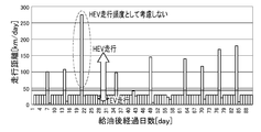
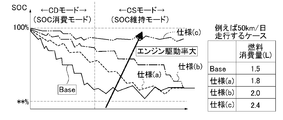
- the fuel supply timing (t1) and the fuel deterioration timing (t2) when maintaining the basic control without switching to the fuel consumption promotion mode in the fuel deterioration suppression control of the embodiment (a) and when switching to the fuel consumption promotion mode (b) It is a time chart which shows the relationship. It is a mileage history figure which shows the example of a case which estimates the mileage per day in the fuel deterioration suppression control of an Example. It is a relationship characteristic figure which shows the example of a case which estimates the days until fuel refueling with respect to the travel distance per day in the fuel deterioration suppression control of an Example. It is a battery SOC characteristic figure which shows the example of a case where an engine drive rate expands in the fuel deterioration suppression control of an Example.
- FIG. 1 shows an overall system configuration of a series-type plug-in hybrid vehicle to which the control device of the embodiment is applied.
- the overall system configuration will be described below with reference to FIG.
- the drive system of the series-type plug-in hybrid vehicle of the embodiment includes an engine 1, a generator motor 2, a drive motor 3 (motor), a battery 4, and a deceleration differential mechanism 5. , Drive wheel 6, generator motor inverter 7, drive motor inverter 8, charge converter 9, switch 10, charge port 11, and fuel tank 14.
- the plug-in hybrid vehicle has an electric vehicle travel mode (hereinafter referred to as “EV travel mode”) and a hybrid vehicle travel mode (hereinafter referred to as “HEV travel mode”) as travel modes.
- EV travel mode is a mode in which the engine 1 is stopped while the drive motor 3 is driven by the electric power stored in the battery 4 and travels using only the drive motor 3 as a drive source.
- HEV running mode is a mode in which the generator motor 2 is driven by the engine 1 for charging or the like while running with the drive motor 3 as a drive source.
- the engine 1 is started by a power generation motor 2 when a power generation request is made, and generates power by driving the power generation motor 2 after a complete explosion. Then, when the generation request is made and the generation request is not made, the engine 1 and the generator motor 2 are stopped.
- the generator motor 2 is a motor generator that is connected to the engine 1 and exhibits a motor function and a power generation function.
- the motor function is exhibited when the engine 1 is started by consuming the power of the battery 4 and igniting following cranking of the engine 1 when a power generation request is made while the engine 1 is stopped.
- the power generation function is exhibited when the engine 1 is in a driving operation state, receives rotational driving power from the engine 1, converts it into three-phase AC power, and charges the battery 4 with the generated power.
- the drive motor 3 is a motor generator that is connected to the drive wheels 6 of the vehicle via a speed-reducing differential mechanism 5 and exhibits a motor function and a power generation function.
- the motor function is exhibited when the vehicle is driven by consuming electric power from the battery 4 at the time of start acceleration, constant speed traveling, or intermediate acceleration.
- the power generation function is exhibited when performing regenerative power generation that receives rotational drive power from the drive wheels 6 during deceleration, braking, etc., converts this into three-phase AC power, and charges the generated power to the battery 4. .
- the battery 4 uses a lithium ion secondary battery, a high-capacity capacitor, or the like, and stores the power generated by the power generation motor 2 or the power regenerated by the drive motor 3 and also stored in the drive motor 3 or the power generation motor 2. Supply power.
- the generator motor inverter 7 is arranged between the generator motor 2 and the battery 4 and mutually converts three-phase alternating current and direct current.
- the three-phase alternating current is used for driving / power generation of the generator motor 2, and the direct current is used for charging / discharging the battery 4.
- the drive motor inverter 8 is disposed between the drive motor 3 and the battery 4 and mutually converts three-phase alternating current and direct current.
- the three-phase alternating current is used for driving / power generation of the drive motor 3, and the direct current is used for charging / discharging the battery 4.
- the charging converter 9 is arranged between the battery 4 and the charging port 11 and converts AC external power supplied from the charging port 11 into DC power that can charge the battery 4 during plug-in charging. .
- the switch 10 is disposed between the generator motor 2, the generator motor inverter 7, and the charging port 11, and switches between a power generation path and a power supply path.
- the power generation path has a pattern in which the charging port 11 is disconnected and the power generation motor 2 and the power generation motor inverter 7 are connected.
- As the power supply path one of the following three patterns is switched and selected.
- a pattern in which the power of the battery 4 is used by disconnecting the charging port 11 and connecting the generator motor 2 and the generator motor inverter 7.
- a pattern in which the electric power of both the charging port 11 and the battery 4 is used by connecting the generator motor 2, the generator motor inverter 7, and the charging port 11.
- a pattern in which the power of the charging port 11 is used by disconnecting the inverter 7 for the generator motor and connecting the generator motor 2 and the charging port 11.
- the charging port 11 is set at any position on the outer periphery of the vehicle body.
- the lid is opened and the power plug 13 of the external charger 12 is inserted and connected.
- the battery 4 is charged (plug-in charging) via the charge converter 9.
- the external charging facility 12 refers to a home charging facility for performing low-speed charging using late-night power at home, a quick charging stand capable of rapid charging at a place away from the home, and the like.
- the fuel tank 14 is a container for storing fuel such as gasoline or light oil supplied to the engine 1.
- the fuel stored in the fuel tank 14 is supplied to the combustion chamber of the engine 1 via a fuel supply passage and a fuel injection device (not shown).
- the control system of the plug-in hybrid vehicle of the embodiment includes an engine controller (ECM) 20, a generator controller (GC) 21, a motor controller (MC) 22, and a battery controller (LBC) 23.
- ECM engine controller
- GC generator controller
- MC motor controller
- LBC battery controller
- Each controller 20, 21, 22, 23, 24 is connected by a CAN communication line 30 capable of exchanging information so that various data can be shared.
- Each of the controllers 20, 21, 22, 23, 24 includes a processor that executes a program, a memory that stores a program executed by the processor, and an interface connected to the processor.
- the engine controller 20 controls the output torque by manipulating the intake air amount, ignition timing, and fuel injection amount of the engine 1 in accordance with a control command from the vehicle integrated controller 24.
- the generator controller 21 outputs an operation command to the generator motor inverter 7 in order to control the input / output torque of the generator motor 2 in accordance with the control command from the vehicle integrated controller 24.
- the motor controller 22 outputs an operation command to the drive motor inverter 8 in order to control the input / output torque of the drive motor 3 in accordance with the control command from the vehicle integrated controller 24.
- the battery controller 23 estimates the internal state quantities such as the charge capacity (remaining capacity) of the battery 4 and the power that can be input / output, and performs protection control of the battery 4.
- the charge capacity (remaining capacity) of the battery 4 is referred to as a battery SOC (SOC is an abbreviation of “State Of Charge”).
- the vehicle integrated controller 24 controls the motor drive output according to the driver's request while coordinating the plurality of controllers 20, 21, 22, and 23 based on the various shared data. In addition, the power generation output is controlled in consideration of both drivability and fuel consumption rate (economic efficiency).
- the vehicle integrated controller 24 inputs information from the navigation controller 25, the ignition key switch 26, the fuel tank sensor 27, and other sensors 28. And the information which should be notified to the passenger
- the navigation controller 25 detects the position of the host vehicle using a GPS signal from a satellite, and has a navigation system control function for searching for a route to a destination and guiding based on map data stored in a DVD or the like. Bear.
- the vehicle position information on the map obtained by the navigation controller 25 is supplied to the vehicle integrated controller 24 together with the home position information and the charging station position information.
- the navigation controller 25 includes an input device (input means) for the passenger to input various information. The occupant can input the destination and the planned travel distance using the input device.
- the ignition key switch 26 is a switch for the ignition device of the engine 1.
- the ignition key switch 26 also serves as a starter motor (cell motor) switch.
- the fuel tank sensor 27 is a sensor for detecting the remaining capacity of the fuel stored in the fuel tank 14, and for example, a fuel level gauge or the like is used.
- the other sensors 28 are various sensors that acquire necessary information such as an accelerator opening sensor and a wheel speed sensor.
- the speaker 29 is a device that outputs sound.
- FIG. 2 shows a configuration and a flow of calculation processing such as a power consumption rate during EV running and a fuel consumption rate during HEV running, which are executed for each run in the vehicle integrated controller 24 of the embodiment.
- a power consumption rate during EV running and a fuel consumption rate during HEV running which are executed for each run in the vehicle integrated controller 24 of the embodiment.
- step S1 it is determined whether or not the ignition key switch 26 is on. If YES (IGN ON), the process proceeds to step S2. If NO (IGN OFF), the process proceeds to the end, and the process is terminated.
- step S2 following the determination that IGN ON in step S1 or step S5, whether or not the current remaining battery charge SOC is greater than a threshold value SOCh set as the SOC lower limit value for shifting to the HEV drive mode Judging. If YES (SOC> SOCh), the process proceeds to step S3. If NO (SOC ⁇ SOCh), the process proceeds to step S4.
- step S3 following the determination in step S2 that SOC> SOCh, that is, the determination that the remaining battery level SOC that maintains the EV driving mode is secured at the present time, the EV driving mode is set as the driving mode. And proceed to step S5.
- step S4 following the determination in step S2 that SOC ⁇ SOCh, that is, the determination that the remaining battery charge SOC has decreased to a level at which it is currently necessary to shift to the HEV driving mode, The HEV travel mode is selected and the process proceeds to step S5.
- step S5 following the selection of the EV traveling mode in step S3 or the selection of the HEV traveling mode in step S4, it is determined whether or not the ignition key switch 26 is OFF. If YES (IGN OFF), the process proceeds to step S6. If NO (IGN ON), the process returns to step S2.
- step S6 following the determination that the IGN is OFF in step S5, the number of days Td (unit “day”) since the previous refueling, the travel distance D (unit “km”), and EV travel
- FCev unit “kWh”
- FChev unit “L”
- the power consumption rate Dev / FCev during EV traveling Calculate (km / kWh).
- HEV calculates the fuel consumption rate Dhev / FChev (km / L) during driving. Then, in addition to the calculated power consumption rate FCev / Dev (km / kWh) during EV driving and the fuel consumption rate FChev / Dhev (km / L) during HEV driving, the number of days elapsed since the last refueling And go to the end.
- the power consumption rate and the fuel consumption rate are expressed as a unit power consumption or a mileage per unit fuel consumption, but conversely, a power consumption or a fuel consumption per unit mileage. Can also be used as a power consumption rate or a fuel consumption rate.
- FIG. 3 shows the configuration and flow of the fuel deterioration suppression control process based on the gap amount between the fuel supply timing and the fuel deterioration timing executed by the vehicle integrated controller 24 of the embodiment.
- Steps S23 to S30 correspond to fuel deterioration suppression control means.
- step S21 the number of days required for fuel refueling or the number of days t1 required for fuel to become zero is estimated and calculated from the present time, and the process proceeds to step S22 (corresponding to fuel consumption estimating means).
- step S22 following the estimation calculation of the number of days required for refueling in step S21 or the number of days required for fuel to become zero, the calculation is performed on the number of days t2 required for fuel deterioration starting from the present, and the process proceeds to step S23.
- Advance corresponds to fuel deterioration estimation means.
- the degree of fuel deterioration is estimated based on the fuel supply timing and the fuel supply amount history. .
- the degree of fuel deterioration is estimated using a determination method based on a sensor output or a decrease in efficiency of the internal combustion engine. Then, the estimated timing at which the estimated degree of fuel deterioration exceeds the fuel deterioration determination threshold is calculated as the number of days t2 required for fuel deterioration.
- step S23 following the estimation calculation of the number of days t2 required for fuel deterioration in step 22, whether the number of days t1 required for fuel refueling or zero fuel is later than the number of days t2 required for fuel deterioration. Determine whether. If YES (t1> t2), the process proceeds to step S25. On the other hand, if NO (t1 ⁇ t2), the process proceeds to step S24.
- step S24 following the determination that t1 ⁇ t2 in step S23, the basic control for suppressing fuel consumption is maintained for high fuel consumption rate performance, and the process proceeds to return.
- step S25 following the determination that t1> t2 in step S23, the mode is switched to the fuel consumption promotion mode that promotes fuel consumption compared to the basic control, and the process proceeds to step S26.
- step S26 following the switching to the fuel consumption promotion mode in step S25, the fuel consumption is promoted in order to bring the number of days t1 required for fuel refueling or zero fuel closer to the number of days t2 required for fuel deterioration as much as possible.
- the engine drive rate expanded to is calculated, and the process proceeds to step S27.
- step S27 following the calculation of the engine drive rate in step S26, in addition to increasing the engine drive rate, as a means for consuming fuel, determination to switch the engine operating point to a fuel consumption operating point shifted from the optimal fuel consumption rate line. And proceed to step S28.
- step S28 following the “engine drive rate UP + determination to switch the engine operating point to the fuel consuming operating point” in step S27, the number of days t1 required for fuel refueling or zero fuel becomes the number of days t2 required for fuel deterioration. It is determined whether or not If YES (t1 ⁇ t2), the process proceeds to return, and if NO (t1> t2), the process proceeds to step S29.
- step S29 following the determination that t1> t2 in step S28, in addition to the engine drive rate expansion and the engine operating point change in steps S25 to S27, the external charging facility 12 moves to the battery 4 mounted on the vehicle.
- the charging upper limit value for plug-in charging is reduced, and the process proceeds to step S30.
- step S30 following the lowering of the charging upper limit value during external charging in step S29, the engine 1 is controlled for the required driving force regardless of whether the condition for switching to the HEV traveling mode in basic control is satisfied or not. To the HEV travel mode in which the battery 4 is driven while charging the power generated by the engine drive, and the process proceeds to return.
- the EV running is performed using the charging power stored in the battery, so that the fuel in the fuel tank may not be consumed for a long time, and the fuel in the tank may be deteriorated.
- the concern of this fuel deterioration is particularly high in a plug-in hybrid vehicle in which sufficient charge power is stored in a high-capacity battery, and a countermeasure for fuel deterioration that suppresses fuel deterioration is required.
- Japanese Patent Laid-Open No. 2010-18128 proposes a technique for performing an engine start timing change process for changing an engine start determination value or a vehicle required power based on an estimated fuel deterioration degree.
- Japanese Patent Application Laid-Open No. 2007-168512 when it is predicted that the fuel property is not appropriate, the engine is operated without performing EV traveling even when the vehicle condition satisfies the normal EV traveling condition. Technologies that consume fuel by driving are proposed. A known technique proposed as a countermeasure against these fuel deteriorations is taken as a comparative example.
- step S24 the basic control for suppressing fuel consumption is maintained with the aim of good fuel consumption rate performance. That is, as shown in FIG. 4 (a), at the present time (t0), it is assumed that the fuel deterioration timing (t2) is later than the fuel supply timing (t1), or that both timings (t1) and (t2) coincide. Thus, the basic control is maintained without entering the fuel consumption promotion mode. In this basic control, as shown in FIG. 2, EV running is maintained as long as the remaining battery charge SOC is SOC> SOCh.
- step S25 the mode is switched to a fuel consumption promotion mode that promotes fuel consumption compared to basic control. That is, as shown in FIG. 4B, at the present time (t0), it is assumed that the fuel deterioration timing (t2) is earlier than the fuel supply timing (t1), so that both timings (t1), (t2) The mode is switched to the fuel consumption promotion mode corresponding to the gap amount.
- This fuel consumption promotion mode is performed by expanding the engine driving rate or changing the engine operating point executed according to the gap amount so that both timings (t1) and (t2) are as close as possible.
- the promotion of fuel consumption is minimized according to the gap amount between the fuel supply timing (t1) and the fuel deterioration timing (t2). While suppressing, the fuel in the fuel tank 14 is used up in accordance with the fuel deterioration timing (t2), so that the deterioration of the fuel is suppressed.
- the number of days t1 required for fuel refueling or zero fuel and the number of days t2 required for fuel deterioration are estimated from the current point, and the fuel refueling timing (t1) is determined as the fuel refueling timing (t1).
- the fuel refueling timing (t1) is determined as the fuel refueling timing (t1).
- a configuration for switching to the fuel consumption promotion mode according to the gap amount is adopted. With this configuration, switching to the fuel consumption promotion mode is properly executed without excess or deficiency based on the predicted estimation of the fuel consumption progress at the fuel refueling timing (t1) and the fuel deterioration progress at the fuel deterioration timing (t2). . Therefore, fuel deterioration is suppressed by using up the fuel in the fuel tank 14 without deteriorating the fuel consumption rate due to switching to the unnecessary fuel consumption promotion mode.
- step S21 in FIG. 3 the number of days required for fuel refueling or the number of days t1 required for fuel to become zero is estimated and calculated from the present.
- at least the following parameter values (1) to (4) are calculated as parameter values necessary for estimating the number of days t1.
- Fuel consumption rate / power consumption rate The fuel consumption rate and the power consumption rate are calculated from predetermined values or values of past user fuel consumption rate / power consumption rate based on the flowchart of FIG.
- Remaining fuel amount until refueling is the amount of fuel calculated from the fuel tank sensor 27 actually contained in the fuel tank 14 or the fuel injection pulse from the engine controller 20 or the like.
- Travel distance per day The travel distance per day is calculated from the user's actual past travel distance history. At this time, if there is a feature in how it is used on weekdays and holidays, it is desirable to divide each average distance. Furthermore, when the user's commute route setting or the future vehicle driving plan and route are set in the navigation information, the estimated mileage can be calculated with higher accuracy by using the value.
- Boarding frequency The boarding frequency is calculated from the user's actual past driving history. Similarly, when the vehicle usage is set in the navigation system in advance, the information is calculated from the information. Then, based on the information of (1) to (4), the number of days t1 required for fuel refueling or the number of days t1 required for fuel zero is estimated to estimate the fuel refueling timing (t1).
- FIG. 5 shows the relationship between the elapsed days [day] after refueling and the travel distance [km / day] in the EV travel mode and the HEV travel mode.
- the mileage in the HEV cruising mode is greatly increased on the 21st day after the refueling.
- the average mileage of the driver per day, the boarding frequency, and the charging pattern history from the external charging equipment 12 are learned and stored.
- the number of days t1 from the present time required until refueling is performed or fuel becomes zero the configuration that estimates
- the EV running performance by the basic control can be ensured by not switching to the fuel consumption promotion mode.
- the mode can be switched to the fuel consumption promotion mode, and the fuel can be used up or the fuel can be supplied before the fuel deteriorates.
- the user set information is, for example, 1.
- User weekday commute route setting This is information on the date and route setting of the travel plan of the user's vehicle. Therefore, it is possible to grasp the user's mileage with higher accuracy by setting the commute route on weekdays. Also, for example, it is possible to grasp in advance the outing schedule for holiday trips, outing schedules during weekday business trips, and the route information. As a result, the fuel supply timing (t1) can be grasped with higher accuracy. As a result, it is possible to prevent the fuel consumption promotion mode from being unnecessarily switched and to actively use the fuel, so that it is possible to ensure an EV travel distance as long as possible without deteriorating the fuel.
- the engine drive rate means the proportion of HEV travel in the total travel (distance or time).
- step S26 in order to make the fuel supply timing (t1) as close as possible to the fuel deterioration timing (t2), the engine drive rate is calculated so as to promote fuel consumption.
- the amount of fuel to be consumed (L) is calculated as follows each time the driver gets on.
- the embodiment it is estimated how much the user has an opportunity to get on the vehicle by the timing when the fuel deteriorates, and the amount of fuel to be consumed before the fuel is supplied or the fuel in the fuel tank Based on the quantity, it is calculated how much fuel should be consumed per ride before fuel deterioration.
- a configuration is adopted in which the drive enlargement rate of the engine 1 is determined from the fuel consumption required per one time and the average mileage information of the driver. Therefore, the fuel in the fuel tank 14 is used up before the fuel deterioration timing (t2) due to the minimum increase in the engine driving rate.
- step S27 in addition to increasing the engine drive rate, as a means for consuming fuel, switching is performed to shift the engine operating point from the fuel consumption optimal line with the lowest fuel consumption to the fuel consumption operating point with the higher fuel consumption. Is done. That is, if the engine drive rate expansion is insufficient for the amount of fuel to be consumed at one time, in addition to the operation for determining the engine drive rate expansion method, for example, the engine operating point is moved to the lower engine speed side. . In this case, as shown in FIG.
- a configuration is adopted in which the operating point of the engine is removed from the optimal fuel consumption operating line that consumes the least amount of fuel, that is, the fuel is operated at the operating point that consumes more fuel. did. Therefore, by switching the engine operating point from the operating point on the optimal fuel consumption line to, for example, an operating point with a low engine speed that can enhance sound vibration performance, the feeling of operating the engine during EV traveling is suppressed. However, more fuel can be consumed, and the fuel in the fuel tank 14 is used up before the fuel deterioration timing (t2).
- step S25 When switched to the fuel consumption promotion mode, the process proceeds from step S25 to step S26 ⁇ step S27 ⁇ step S28 in the flowchart of FIG. If it is determined in step S28 that t1 ⁇ t2 is likely to occur, the flow of steps S21 ⁇ step S22 ⁇ step S23 ⁇ step S25 ⁇ step S26 ⁇ step S27 ⁇ step S28 is repeated in the flowchart of FIG. It is.
- step S28 plug-in charging from the external charging facility 12 to the battery 4 is performed based on a prediction determination that the fuel refueling timing (t1) will be later than the fuel deterioration timing (t2) even if the fuel acceleration mode is switched. The charge upper limit at that time is lowered.
- step S30 regardless of the remaining battery capacity SOC, the engine 1 is driven, and the mode is switched to the HEV travel mode in which the vehicle 1 travels while charging the battery 4 with the power generated by the engine drive.
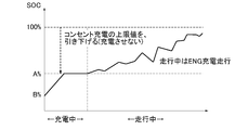
- the charging upper limit value for plug-in charging is reduced to A% ( ⁇ 100%).
- the amount of charging by plug-in charging is ensured during traveling, and the engine drive rate is increased.
- the engine 1 when the charging upper limit is set to 30% of the maximum battery charging capacity, the engine 1 outputs as much power as the battery 4 mounted on the vehicle is charged in addition to the power output operation necessary for normal driving, and the battery Switch to control that charges to 100% charge capacity.
- the battery Switch to control that charges to 100% charge capacity.
- FIG. 9 it is possible to output more engines 1 than the required traveling power, and it is possible to consume fuel that may be deteriorated.
- the fuel is converted into electric energy and stored in the battery 4 mounted on the vehicle. Therefore, EV traveling can be performed after refueling is completed.
- the vehicle-mounted battery 4 is further charged, so that the engine can be operated with an output that is greater than the vehicle traveling power. Thereby, more fuel can be consumed.
- the additional consumed fuel is stored in the battery 4 as electric energy, it is possible to travel from EV traveling because the battery energy is stored after refueling.
- the embodiment includes an engine 1 that is driven by supplying fuel from a fuel tank 14, and A drive motor 3 (motor) for driving the drive wheels 6 and 6 by at least power supply from the battery 4; Fuel consumption estimation means (step S21) for estimating a period (number of days t1) required for fuel refueling or fuel zero from the present time; Fuel deterioration estimation means (step S22) for estimating a period (days t2) required for fuel deterioration starting from the present time; When the fuel refueling timing or the fuel zero timing (fuel refueling timing (t1)) is after the fuel degrading timing (fuel deterioration timing (t2)) (YES in step S23), both timings (1 ), (2) fuel deterioration suppression control means (steps S23 to S30) for switching to the fuel consumption promotion mode according to the gap amount; Is provided. For this reason, it is possible to suppress the deterioration of the fuel without causing a decrease in the fuel consumption rate by appropriately switching to the fuel consumption promotion mode based on the
- the fuel consumption estimating means (step S21) estimates the number of days t1 required for fuel refueling or zero fuel from the present as a starting point
- the fuel deterioration estimation means (step S22) estimates the number of days t2 required for fuel deterioration starting from the present. For this reason, in addition to the effect of (1), switching to the fuel consumption promotion mode has been made based on the prediction estimation of fuel consumption progress and fuel deterioration progress on a daily basis while ensuring good estimation accuracy and suppressing the delay in prediction timing. It can be executed properly.
- the fuel consumption estimating means learns and stores the average driving distance per day, the boarding frequency of the driver, and the charging pattern history from the external charging equipment 12, and in addition to these stored information, external charging Based on the estimated motor travelable distance after the battery 12 is charged by the facility 12 and the estimated fuel consumption rate value, the period (number of days t1) required from the present to fuel refueling or zero fuel is estimated. For this reason, in addition to the effect of (1) or (2) above, the estimation accuracy of fuel refueling or the timing when fuel becomes zero (fuel refueling timing (t1)) is increased, and the necessity of switching to the fuel consumption promotion mode is determined. Accuracy can be improved.
- step S26 When the fuel deterioration suppression control means (step S26) is switched to the fuel consumption promotion mode, the fuel that should be consumed by one boarding in the period from the present time to the fuel deterioration timing (t2).
- the engine driving rate is calculated based on the amount and the average driving distance information of the driver, and the engine is operated with the calculated engine driving rate. For this reason, in addition to the effects (1) to (3) above, fuel consumption is promoted while minimizing the increase in engine drive rate, which reduces the fuel consumption rate performance, and the fuel is adjusted to the fuel deterioration timing (t2).
- the inside of the tank 14 can be emptied.
- step S27 When the fuel deterioration suppression control means (step S27) is switched to the fuel consumption promotion mode, the operation is performed at the fuel consumption operating point with the engine operating point removed from the optimum fuel consumption line. Therefore, in addition to the effects (1) to (4) above, fuel consumption is promoted while suppressing the feeling of engine operation during EV travel, and the fuel tank 14 is emptied in accordance with the fuel deterioration timing (t2). be able to.
- step S29 sets an upper limit value for the charge amount charged from the external charging facility 12 to the battery 4 in addition to at least increasing the engine drive rate. For this reason, in addition to the effect of (4) or (5) above, fuel consumption can be promoted by an increase in the engine driving rate by securing a charging margin for the battery 4.
- step S30 when the vehicle travels after charging with the upper limit charging amount from the external charging facility 12, is charged to the battery 4 for the required driving force.
- the engine 1 is driven by the engine output to which is added. For this reason, in addition to the effect of (6) above, fuel consumption can be promoted by driving the engine with an output greater than the required traveling power, and the added fuel consumption can be converted into battery energy and stored, so that EV driving frequency can be increased.
- the fuel consumption estimation means (step S21) estimates the travel distance using the user set information if there is user set information in the navigation system in advance. For this reason, in addition to the effects (1) to (7) above, grasping the fuel refueling timing (t1) with high accuracy suppresses unnecessary switching to the fuel consumption promotion mode and suppresses fuel deterioration. However, the longest EV travel distance can be secured.
- control apparatus of the hybrid vehicle of this invention has been demonstrated based on the Example, about a specific structure, it is not restricted to this Example, The summary of the invention which concerns on each claim of a claim As long as they do not deviate, design changes and additions are permitted.
- the fuel consumption estimating means is a means for estimating the number of days t1 required for fuel refueling or zero fuel from the present as the starting point, and the fuel deterioration estimating means is required from the present as the starting point to the fuel deterioration.
- a means to estimate the number of days t2 is presented.
- the period of the fuel consumption estimation means may be an example of estimating the time required for fuel supply or zero fuel, or the month, etc., starting from the present.
- the period of the fuel deterioration estimation means may be an example of estimating the time required for fuel deterioration or the month from the present.
- the unit of the period may be changed from month ⁇ day ⁇ time as the fuel refueling or the fuel approaches zero or the fuel deterioration approaches.
- step S21 of FIG. 3 the average driving distance per day, the boarding frequency of the driver, and the charging pattern history from the external charging facility 12 are learned and stored.
- the number of days t1 from the present until the fuel is supplied or the fuel becomes zero is calculated.
- An example of estimation is given.
- the amount of fuel until refueling may be the amount of fuel in the fuel tank, and it is more preferable to consider the average remaining fuel amount when refueling in the past.
- the estimated EV travelable distance and the estimated fuel consumption rate value may be predetermined values, or the past power consumption rate value and the actual value learning of the fuel consumption rate value that can take into account differences in driving methods and seasonal differences. But it ’s okay.
- an example of estimating and calculating the number of days t2 until fuel deterioration using the fuel deterioration estimation calculation method described in Japanese Patent Application Laid-Open No. 2009-255680 and Japanese Patent Application Laid-Open No. 2007-168512 in Step S22 of FIG. showed that.
- the oxidation of the fuel is detected directly or indirectly, and the number of days until the fuel deterioration is estimated by predicting the timing when the oxidation value of the fuel exceeds the deterioration judgment threshold.
- An example of this is also possible.
- the engine driving rate is increased by stepwise increasing the threshold value SOCh of the remaining battery capacity SOC that shifts to the HEV traveling mode from the lower limit value by the basic control in step S26 of FIG.
- the predetermined value of the accelerator opening is used. It may be an example of lowering stepwise or steplessly.
- the vehicle speed threshold may be lowered stepwise or steplessly.
- step S27 of FIG. 3 an example of changing the engine operating point to the fuel consumption operating point shifted from the fuel consumption rate optimal line in addition to increasing the engine driving rate as means for promoting fuel consumption is shown. It was. However, this engine operating point change may be added to the increase of the engine drive rate. For example, when fuel consumption is not required until the engine drive rate is increased, the engine drive rate is not changed and the engine drive rate is not changed. It is only necessary to change the operating point.
- an engine drive rate expansion means As an example of means for promoting fuel consumption, an engine drive rate expansion means, an engine operating point changing means from a fuel consumption rate optimum line, and a plug-in charge amount limiting means are shown.
- the means for promoting fuel consumption is not limited to these means.
- other means for promoting fuel consumption such as a means for prohibiting engine idle stop operation, may be used.
- two or more means for promoting a plurality of fuel consumptions are appropriately combined may be used.
- the mode when the mode is switched to the fuel consumption promotion mode, an example is shown in which the fuel consumption promotion mode is executed without particularly notifying the driver or the occupant.
- the mode when the mode is switched to the fuel consumption promotion mode, it may be an example of notifying the driver or the occupant of the fuel consumption promotion mode through a navigation screen or a speaker. In this case, there is an effect of prompting the driver to refuel.
- control device of the present invention is applied to a series-type plug-in hybrid vehicle including a generator motor and a drive motor (two motors).
- the control device of the present invention is applicable to a parallel type plug-in hybrid vehicle having two motors, a parallel type plug-in hybrid vehicle having a motor generator (one motor) for both power generation and driving, and the like. Can be applied.
- the present invention can be applied to a hybrid vehicle that frequently uses EV traveling, such as a parallel hybrid vehicle in which plug-in charging is impossible.
Landscapes
- Engineering & Computer Science (AREA)
- Mechanical Engineering (AREA)
- Transportation (AREA)
- Power Engineering (AREA)
- Combustion & Propulsion (AREA)
- Chemical & Material Sciences (AREA)
- Automation & Control Theory (AREA)
- Sustainable Energy (AREA)
- Sustainable Development (AREA)
- Life Sciences & Earth Sciences (AREA)
- General Engineering & Computer Science (AREA)
- Physics & Mathematics (AREA)
- Mathematical Physics (AREA)
- Electric Propulsion And Braking For Vehicles (AREA)
- Hybrid Electric Vehicles (AREA)
- Control Of Vehicle Engines Or Engines For Specific Uses (AREA)
- Combined Controls Of Internal Combustion Engines (AREA)
Abstract
Description
前記エンジンは、燃料タンクからの燃料供給により駆動する。
前記モータは、少なくともバッテリからの電力供給により駆動輪を駆動する。
前記燃料消費推定手段は、現在を起点として、次の燃料給油までに要する期間もしくは燃料残量が実質的にゼロになるまでに要する期間を推定する。
前記燃料劣化推定手段は、現在を起点として、燃料劣化までに要する期間を推定する。
前記燃料劣化抑制制御手段は、前記燃料給油もしくは前記燃料ゼロになるタイミングが、前記燃料劣化になるタイミングの後である場合、両タイミングのギャップ量(つまり両タイミングの差)に応じた燃料消費促進モードへ切り替える。
このように、燃料消費進行と燃料劣化進行の予測推定に基づき、燃料消費促進モードへの切り替えを適正に実行することにより、燃料消費率の低下を招くことなく、燃料の劣化を抑制することができる。
図1は、実施例の制御装置が適用されたシリーズ方式のプラグイン・ハイブリッド車両の全体システム構成を示す。以下、図1に基づき全体システム構成を説明する。
・充電ポート11を切り離し、発電モータ2と発電モータ用インバータ7を接続することで、バッテリ4の電力を使用するパターン。
・発電モータ2と発電モータ用インバータ7と充電ポート11を接続することで、充電ポート11とバッテリ4の双方の電力を使用するパターン。
・発電モータ用インバータ7を切り離し、発電モータ2と充電ポート11を接続することで、充電ポート11の電力を使用するパターン。
なお、各コントローラ20、21、22、23、24は、各種データを共有化できるように、情報交換が可能なCAN通信線30により接続されている。また、各コントローラ20、21、22、23、24は、プログラムを実行するプロセッサと、プロセッサによって実行されるプログラムを格納するメモリと、プロセッサに接続されたインターフェースと、を備える。
なお、この例では、電力消費率および燃料消費率を、単位電力消費量ないし単位燃料消費量当たりの走行距離でもって表しているが、逆に、単位走行距離当たりの電力消費量ないし燃料消費量を電力消費率ないし燃料消費率として用いることもできる。
ここで、燃料劣化までに要する日数t2の推定演算手法としては、例えば、特開2009-255680号公報に記載されているように、給油時期及び給油量履歴に基づいて、燃料劣化度合いを推定する。あるいは、特開2007-168512号公報に記載されているように、センサ出力や内燃機関の効率低下からの判断方法を用い、燃料劣化度合いを推定する。そして、推定された燃料劣化度合いが、燃料劣化判定閾値を超えると推定されるタイミングを燃料劣化までに要する日数t2として演算する。
一方、NO(t1≦t2)の場合はステップS24へ進む。
まず、「比較例の課題」の説明を行う。続いて、実施例のプラグイン・ハイブリッド車両の制御装置における作用を、「燃料使い切りによる燃料劣化抑制作用」、「燃料給油タイミングの推定作用」、「エンジン駆動率の拡大作用」、「最適燃料消費線外しによるエンジン駆動作用」、「プラグイン充電量の制限作用」に分けて説明する。
ハイブリッド車両においては、バッテリに蓄えられている充電電力を使ってEV走行が行われることで、長期間にわたり燃料タンク内の燃料が消費されないことがあり、タンク内燃料が劣化してしまう懸念がある。この燃料劣化の懸念は、特に、高容量のバッテリに十分な充電電力が蓄えられるプラグイン・ハイブリッド車両において高くなり、燃料劣化を抑制する燃料劣化対策が必要となる。
単にエンジン運転頻度を高めるに留まっており、燃料劣化タイミングに基づいた具体的なエンジン駆動負荷率を規定しておらず、エンジン運転頻度を高めても結果的に燃料が消費しきれず、燃料が劣化してしまう懸念が生じる。
本来はエンジン運転領域を拡大しなくても、燃料が消費でき、劣化懸念が無いようなシーンでも、エンジン運転領域を拡大したことで、ランニングコストの低いEV走行をできる機会を減少させてしまう。
本来、車両の使い方(例えば、1日の走行距離等)はユーザー毎に異なるのであるが、そのユーザー毎の車両の使い方の差異に対するエンジン運転動作を規定していない。このため、あるユーザーに対しては効果が出ても、あるユーザーに対しては効果が出ない、もしくは逆効果になる可能性があり、各ユーザーに対するロバスト性を持った効果が低かった。
上記のように、燃料劣化対策としては、EV走行の機会を減少させることなく、燃料劣化の抑制効果に確実性を持たせることが必要である。以下、これを反映する燃料使い切りによる燃料劣化抑制作用を説明する。
なお、以下の説明において、燃料給油もしくは燃料ゼロになるのに要する日数t1によるタイミングを「燃料給油タイミング(t1)」といい、燃料劣化になるのに要する日数t2によるタイミングを「燃料劣化タイミング(t2)」という。
すなわち、図4(a)に示すように、現時点(t0)において、燃料給油タイミング(t1)より燃料劣化タイミング(t2)のほうが遅い、あるいは、両タイミング(t1),(t2)が一致すると想定されることで、燃料消費推進モードとすることなく、基本制御が維持される。この基本制御では、図2に示すように、バッテリ残容量SOCが、SOC>SOChである限りEV走行を維持する。そして、HEV走行が選択されても、可能な限りエンジン1を燃料消費最適線に沿って駆動する。
したがって、燃料給油タイミング(t1)と燃料劣化タイミング(t2)が一致するとき、あるいは、燃料給油タイミング(t1)より燃料劣化タイミング(t2)が遅いと想定されたときは、エンジン駆動率等を拡大しなくても、燃料が劣化する前に燃料を使い切ることができる。つまり、燃料劣化懸念が無いようなシーンであるため、比較例技術のように、燃料消費促進モードへの切り替えが必要以上に実行されることによる燃料消費率の悪化やEV走行の機会減少を招かない。
すなわち、図4(b)に示すように、現時点(t0)において、燃料給油タイミング(t1)より燃料劣化タイミング(t2)のほうが早いと想定されることで、両タイミング(t1),(t2)のギャップ量に応じた燃料消費促進モードへ切り替えられる。この燃料消費促進モードは、両タイミング(t1),(t2)を極力近づけるようにギャップ量に応じて実行されるエンジン駆動率拡大やエンジン運転点変更、等により行う。
したがって、燃料給油タイミング(t1)より燃料劣化タイミング(t2)が早いと想定されたときは、燃料給油タイミング(t1)と燃料劣化タイミング(t2)のギャップ量に応じて燃料消費促進を最小限に抑えながらも、燃料劣化タイミング(t2)に符合して燃料タンク14内の燃料が使い切られることで、燃料の劣化が抑制される。
この構成により、燃料給油タイミング(t1)による燃料消費進行と燃料劣化タイミング(t2)による燃料劣化進行の予測推定に基づき、燃料消費促進モードへの切り替えが過不足無く適正に実行されることになる。
したがって、不要な燃料消費促進モードへの切り替えによる燃料消費率の悪化を招くことなく、燃料タンク14内の燃料使い切りにより燃料の劣化が抑制される。
上記燃料劣化抑制作用において、燃料消費促進モードへの切り替え必要性の判断精度を上げるには、給油または燃料ゼロまでに要する日数t1による燃料給油タイミング(t1)を、いかに精度良く推定するかが重要である。以下、これを反映する燃料給油タイミング(t1)の推定作用を説明する。
このとき、日数t1を推定演算するのに必要なパラメータ値として、最低でも下記(1)~(4)のパラメータ値を算出しておく。
(1) 燃料消費率・電力消費率
燃料消費率と電力消費率は、予め定めた値、もしくは、図2のフローチャートに基づく過去のユーザー燃料消費率・電力消費率の値から演算する。
(2) 給油までの残燃料量
給油までの残燃料量は、実際に燃料タンク14内に入っている燃料タンクセンサ27から算出された燃料量、もしくは、エンジンコントローラ20等からの燃料噴射パルスを積分した値から算出した燃料量をもとに、ユーザーの残り何リットルを残して給油するのかのパターン学習した値を考慮して算出する。
(3) 1日あたりの走行距離
1日あたりの走行距離は、ユーザーの実際の過去の走行距離履歴から演算する。この時、平日と休日とで使われ方に特徴が出ている場合は、それぞれの平均距離を分けることが望ましい。更に、ナビゲーション情報で、ユーザーの通勤ルート設定や、これからの車両運転計画とルートが設定されている場合には、その値を用いることで、より高い精度で推定走行距離演算が可能となる。
(4) 乗車頻度
乗車頻度は、ユーザーの実際の過去の走行履歴より演算する。この時も同様に、車両使われ方が予めナビゲーションシステムに設定されている場合には、その情報より算出する。そして、これら(1)~(4)の情報に基づいて、燃料給油までに要する日数t1、もしくは、燃料ゼロまでに要する日数t1を見積もり、燃料給油タイミング(t1)を推定する。
例えば、図5の例においては、給油後の経過日数が21日目の日における、HEV走行モードでの走行距離が飛びぬけて多くなっているというように、過去の走行距離履歴の中でイレギュラーな走行距離履歴が存在する場合がある。仮に、このようなイレギュラーな走行距離履歴を加味して、1日あたりの走行距離を推定演算すると、推定演算された1日あたりの走行距離に基づいて算出される燃料給油までに要する日数t1、もしくは、燃料がゼロになるまでに要する日数t1に誤差が生じてしまう。そこで、1日あたりの走行距離を推定演算する場合、このようなイレギュラーな走行距離履歴を除いた平均値により演算することが望ましい。これにより、正確な1日あたりの走行距離を推定演算することができる。
ここで、ユーザーセット情報とは、例えば、
1.ユーザーの平日の通勤ルート設定
2.ユーザーの車両の走行計画の、日付とその時のルート設定
の情報をいう。
したがって、平日の通勤ルート設定により、より高い精度でユーザーの走行距離を把握することができ、また、例えば、休日の遠出計画や、平日の出張等での遠出スケジュールとそのルート情報が事前に把握できることで、より高い精度で、燃料給油タイミング(t1)が把握される。これにより、不必要に燃料消費促進モードへ切り替えて燃料を積極的に使うことを抑制できることで、燃料劣化させることなく、極力長いEV走行距離を確保することが可能となる。
上記燃料消費促進モードへ切り替えられたとき、エンジン駆動率の拡大を、燃料給油タイミング(t1)と燃料劣化タイミング(t2)のギャップ量に対応して行うことが必要である。以下、これを反映するエンジン駆動率の拡大作用を説明する。
なお、ここでエンジン駆動率とは、総走行(距離もしくは時間)の中に占めるHEV走行の割合を意味する。
このエンジン駆動率の算出方法としては、ドライバーが1回乗車するたびに、消費すべき燃料量(L)を以下のように算出する。
燃料劣化までの推定乗車回数(N)=燃料劣化タイミング(t2)×乗車頻度(回/日)1回あたりの乗車で消費すべき燃料量(L)=燃料給油までの残燃料(L)÷N(回)これにより1回の乗車あたりに必要な消費すべき燃料量が求められ、この値と、推定EV距離、燃料消費率値、ドライバーの平均走行距離より、エンジン駆動率を決定する。
したがって、最小限のエンジン駆動率の拡大により、燃料劣化タイミング(t2)になる前に燃料タンク14内の燃料が使い切られる。
上記燃料消費促進モードへ切り替えられたとき、エンジン駆動率の拡大だけではギャップ量に対応できないときは、更なる燃料消費手法を加えることが必要である。以下、これを反映する最適燃料消費線外しによるエンジン駆動作用を説明する。
すなわち、エンジン駆動率拡大では1回あたりに消費すべき燃料量に不足する場合には、エンジン駆動率の拡大方法を決定する動作に加え、例えば、エンジン動作点をエンジン回転数が低い側へ動かす。この場合、図8に示すように、燃料消費最適線と等パワー線が交わるエンジン回転数から、音振・加速フィーリング優先線と等パワー線が交わるエンジン回転数へと低下させることで、音振性能向上が狙える。このため、本来、EV走行できるところでエンジン1を運転させることによる生じる運転者の感覚の悪化を、最小限に抑制することができる。
したがって、エンジン動作点を、最適燃料消費線上の動作点から、例えば、音振性能を高められるエンジン回転数が低い動作点へ切り替えることで、EV走行中にエンジンが動作している感覚を抑制しながら、より多くの燃料を消費することが可能になり、燃料劣化タイミング(t2)になる前に燃料タンク14内の燃料が使い切られる。
上記燃料消費促進モードへ切り替えられたとき、エンジン駆動率拡大とエンジン動作点変更だけではギャップ量に対応できないときは、更なる燃料消費手法を追加することが必要である。以下、これを反映するプラグイン充電量の制限作用を説明する。
したがって、電気エネルギーの外部からの充電量を抑制することにより、エンジン駆動率が高まることで、より燃料を消費することが可能となる。
したがって、車両が走行するのに必要なパワーをエンジン1が駆動するのに加え、更に車載のバッテリ4へ充電させることで、車両走行必要パワー以上の出力でエンジン運転をさせることができる。それにより、更に多くの燃料が消費することができる。加えて、この追加で消費した燃料は、バッテリ4へ電気エネルギーとして蓄積されるため、燃料を給油した後、電池エネルギーを蓄えている状態なため、EV走行から走行することが可能となる。
少なくともバッテリ4からの電力供給により駆動輪6,6を駆動する駆動モータ3(モータ)と、
現在を起点として、燃料給油もしくは燃料ゼロになるまでに要する期間(日数t1)を推定する燃料消費推定手段(ステップS21)と、
現在を起点として、燃料劣化までに要する期間(日数t2)を推定する燃料劣化推定手段(ステップS22)と、
前記燃料給油もしくは前記燃料ゼロになるタイミング(燃料給油タイミング(t1))が、前記燃料劣化になるタイミング(燃料劣化タイミング(t2))の後である場合(ステップS23でYES)、両タイミング(1),(2)のギャップ量に応じた燃料消費促進モードへ切り替える燃料劣化抑制制御手段(ステップS23~ステップS30)と、
を備える。
このため、燃料消費進行と燃料劣化進行の予測推定に基づき、燃料消費促進モードへの切り替えを適正に実行することにより、燃料消費率の低下を招くことなく、燃料の劣化を抑制することができる。
前記燃料劣化推定手段(ステップS22)は、現在を起点として、燃料劣化までに要する日数t2を推定する。
このため、(1)の効果に加え、良好な推定精度を確保しつつ予測タイミングの遅れを抑えた日単位による燃料消費進行と燃料劣化進行の予測推定に基づき、燃料消費促進モードへの切り替えを適正に実行することができる。
このため、上記(1)または(2)の効果に加え、燃料給油もしくは前記燃料ゼロになるタイミング(燃料給油タイミング(t1))の推定精度が高まり、燃料消費促進モードへの切り替え必要性の判断精度を向上させることができる。
このため、上記(1)~(3)の効果に加え、燃料消費率性能を低下させるエンジン駆動率の拡大を最小限に抑えながら燃料消費を促進し、燃料劣化タイミング(t2)に合わせて燃料タンク14内を空にすることができる。
このため、上記(1)~(4)の効果に加え、EV走行中におけるエンジン運転感を抑制しながら燃料消費を促進し、燃料劣化タイミング(t2)に合わせて燃料タンク14内を空にすることができる。
このため、上記(4)または(5)の効果に加え、バッテリ4への充電余裕を確保することでのエンジン駆動率の高まりにより、燃料消費を促進することができる。
このため、上記(6)の効果に加え、走行必要パワー以上の出力によるエンジン駆動により燃料消費を促進できると共に、追加した消費燃料を電池エネルギーに変換して蓄えることにより、燃料給油後の走行時におけるEV走行頻度を高めることができる。
このため、上記(1)~(7)の効果に加え、高い精度で燃料給油タイミング(t1)を把握することにより、不必要な燃料消費促進モードへの切り替えが抑えられ、燃料劣化を抑制しながら、最大限に長いEV走行距離を確保することができる。
Claims (10)
- 燃料タンクからの燃料供給により駆動するエンジンと、
少なくともバッテリからの電力供給により駆動輪を駆動するモータと、
現在を起点として、燃料給油もしくは燃料ゼロになるまでに要する期間を推定する燃料消費推定手段と、
現在を起点として、燃料劣化までに要する期間を推定する燃料劣化推定手段と、
前記燃料給油もしくは前記燃料ゼロになるタイミングが、前記燃料劣化になるタイミングの後である場合、燃料消費促進モードへ切り替える燃料劣化抑制制御手段と、
を備えるハイブリッド車両の制御装置。 - 請求項1に記載されたハイブリッド車両の制御装置において、
前記燃料消費推定手段は、現在を起点として、燃料給油もしくは燃料ゼロになるまでに要する日数を推定し、
前記燃料劣化推定手段は、現在を起点として、燃料劣化までに要する日数を推定する、ハイブリッド車両の制御装置。 - 請求項1に記載されたハイブリッド車両の制御装置において、
前記燃料消費推定手段は、ドライバーの1日あたりの平均走行距離、乗車頻度、外部充電設備からの充電パターン履歴を学習記憶し、これらの記憶情報に加え、外部充電設備による前記バッテリへの充電後からの推定されるモータ走行可能距離と推定燃料消費率値より、現在から燃料給油もしくは燃料ゼロになるまでに要する期間を推定する、ハイブリッド車両の制御装置。 - 請求項1に記載されたハイブリッド車両の制御装置において、
前記燃料劣化抑制制御手段は、燃料消費促進モードへ切り替えられると、現時点から燃料劣化タイミングになるまでの期間における1回あたりの乗車で必要な消費すべき燃料量とドライバーの平均走行距離情報によりエンジン駆動率を算出し、算出したエンジン駆動率によるエンジン運転を実施する、ハイブリッド車両の制御装置。 - 請求項1に記載されたハイブリッド車両の制御装置において、
前記燃料劣化抑制制御手段は、燃料消費促進モードにおいて、エンジン動作点を最適燃料消費線から外した燃料消費動作点による運転とするハイブリッド車両の制御装置。 - 請求項1に記載されたハイブリッド車両の制御装置において、
前記燃料劣化抑制制御手段は、外部充電設備から前記バッテリへ充電する充電量の上限値を低くする、ハイブリッド車両の制御装置。 - 請求項6に記載されたハイブリッド車両の制御装置において、
前記燃料劣化抑制制御手段は、前記外部充電設備からの上限充電量による充電を実施した後に車両走行する際、要求駆動力分に前記バッテリへの充電駆動力分を加えたエンジン出力により前記エンジンを駆動する、ハイブリッド車両の制御装置。 - 請求項1に記載されたハイブリッド車両の制御装置において、
前記燃料消費推定手段は、ユーザーの消費燃料を推定する際、予めナビゲーションシステムでのユーザーセット情報があれば、ユーザーセット情報を用いて走行距離を推定する、ハイブリッド車両の制御装置。 - 請求項1に記載されたハイブリッド車両の制御装置において、
前記燃料消費促進モードは複数種類の燃料消費促進手段を含み、前記燃料劣化抑制制御手段は、前記燃料給油もしくは前記燃料ゼロになるタイミングと前記燃料劣化になるタイミングとのギャップ量に応じて、1つもしくは複数の燃料消費促進手段を選択する、ハイブリッド車両の制御装置。 - 燃料タンクからの燃料供給により駆動するエンジンと、少なくともバッテリからの電力供給により駆動輪を駆動するモータと、を備えてなるハイブリッド車両において、
現在を起点として、燃料給油もしくは燃料ゼロになるまでに要する期間を推定し、
現在を起点として、燃料劣化までに要する期間を推定し、
前記燃料給油もしくは前記燃料ゼロになるタイミングが、前記燃料劣化になるタイミングの後である場合には、燃料消費促進処理を実行する、ハイブリッド車両の制御方法。
Priority Applications (2)
| Application Number | Priority Date | Filing Date | Title |
|---|---|---|---|
| CN201280002824.1A CN103097221B (zh) | 2011-01-25 | 2012-01-17 | 混合动力车辆的控制装置以及控制方法 |
| US13/817,770 US9221457B2 (en) | 2011-01-25 | 2012-01-17 | Hybrid vehicle control apparatus and control method |
Applications Claiming Priority (4)
| Application Number | Priority Date | Filing Date | Title |
|---|---|---|---|
| JP2011012913 | 2011-01-25 | ||
| JP2011-012913 | 2011-01-25 | ||
| JP2011257735A JP5923944B2 (ja) | 2011-01-25 | 2011-11-25 | ハイブリッド車両の制御装置 |
| JP2011-257735 | 2011-11-25 |
Publications (1)
| Publication Number | Publication Date |
|---|---|
| WO2012102123A1 true WO2012102123A1 (ja) | 2012-08-02 |
Family
ID=46580695
Family Applications (1)
| Application Number | Title | Priority Date | Filing Date |
|---|---|---|---|
| PCT/JP2012/050785 Ceased WO2012102123A1 (ja) | 2011-01-25 | 2012-01-17 | ハイブリッド車両の制御装置および制御方法 |
Country Status (4)
| Country | Link |
|---|---|
| US (1) | US9221457B2 (ja) |
| JP (1) | JP5923944B2 (ja) |
| CN (1) | CN103097221B (ja) |
| WO (1) | WO2012102123A1 (ja) |
Cited By (1)
| Publication number | Priority date | Publication date | Assignee | Title |
|---|---|---|---|---|
| EP3446939A1 (en) * | 2017-08-23 | 2019-02-27 | Mitsubishi Jidosha Kogyo Kabushiki Kaisha | Fuel maintenance guide system for vehicle |
Families Citing this family (30)
| Publication number | Priority date | Publication date | Assignee | Title |
|---|---|---|---|---|
| JP5692123B2 (ja) * | 2012-03-05 | 2015-04-01 | アイシン・エィ・ダブリュ株式会社 | 車両の充電制御システム、車両の充電制御方法、及び車両の充電制御プログラム |
| US9415762B2 (en) * | 2012-04-05 | 2016-08-16 | Ford Global Technologies, Llc | Engine operation for plug-in hybrid electric vehicle |
| JP5974839B2 (ja) * | 2012-11-06 | 2016-08-23 | トヨタ自動車株式会社 | ハイブリッド車両の制御装置 |
| JP5700061B2 (ja) | 2013-03-21 | 2015-04-15 | トヨタ自動車株式会社 | ハイブリッド車 |
| JP6024584B2 (ja) | 2013-04-19 | 2016-11-16 | トヨタ自動車株式会社 | ハイブリッド車両 |
| JP2015011576A (ja) * | 2013-06-28 | 2015-01-19 | 株式会社東芝 | 蓄電池駆動車両の運行システム |
| US9008880B2 (en) * | 2013-07-15 | 2015-04-14 | Ford Global Technologies, Llc | Method and system for a plug-in hybrid electric vehicle |
| CN104842996B (zh) * | 2014-06-18 | 2017-10-10 | 北汽福田汽车股份有限公司 | 一种混合动力汽车换挡方法及系统 |
| JP6036752B2 (ja) * | 2014-06-24 | 2016-11-30 | トヨタ自動車株式会社 | 車両およびその制御方法 |
| US10048082B2 (en) | 2014-08-29 | 2018-08-14 | Ford Global Technologies, Llc | Route and model based energy estimation |
| US9476719B2 (en) * | 2014-08-29 | 2016-10-25 | Ford Global Technologies, Llc | Route-based distance to empty calculation for a vehicle |
| US9688270B2 (en) | 2015-09-25 | 2017-06-27 | Ford Global Technologies, Llc | Vehicle fuel maintenance systems and methods |
| JP6361681B2 (ja) * | 2016-03-30 | 2018-07-25 | トヨタ自動車株式会社 | ハイブリッド自動車 |
| JP2017178083A (ja) * | 2016-03-30 | 2017-10-05 | トヨタ自動車株式会社 | ハイブリッド自動車 |
| KR101807142B1 (ko) | 2016-05-17 | 2017-12-07 | 현대자동차 주식회사 | 하이브리드 자동차 엔진 제어 장치 및 방법 |
| JP6515875B2 (ja) * | 2016-06-10 | 2019-05-22 | 株式会社デンソー | 車載電源システム |
| JP2018001788A (ja) * | 2016-06-27 | 2018-01-11 | パナソニックIpマネジメント株式会社 | 充電制御装置、及び充電制御プログラム |
| JP6551332B2 (ja) * | 2016-07-26 | 2019-07-31 | トヨタ自動車株式会社 | 車両の走行可能距離算出システムおよび走行可能距離算出方法 |
| JP6729161B2 (ja) * | 2016-08-12 | 2020-07-22 | トヨタ自動車株式会社 | ハイブリッド車両 |
| JP6466892B2 (ja) | 2016-10-20 | 2019-02-06 | 株式会社Subaru | プラグインハイブリッド車両の制御装置 |
| US10573102B2 (en) * | 2017-02-10 | 2020-02-25 | Mitsubishi Jidosha Kogyo Kabushiki Kaisha | Fuel maintenance guide system in hybrid vehicle |
| JP7081130B2 (ja) * | 2017-02-10 | 2022-06-07 | 三菱自動車工業株式会社 | 燃料メンテナンスガイドシステム |
| JP7006074B2 (ja) * | 2017-03-10 | 2022-01-24 | 三菱自動車工業株式会社 | 燃料メンテナンスガイドシステム |
| JP7056453B2 (ja) * | 2018-08-03 | 2022-04-19 | トヨタ自動車株式会社 | シリーズハイブリッド車両の発電制御装置 |
| JP7393872B2 (ja) * | 2019-03-20 | 2023-12-07 | 株式会社Subaru | 駆動システム |
| CN111746352B (zh) * | 2019-03-29 | 2022-01-28 | 北京新能源汽车股份有限公司 | 一种确定功率混合型电动汽车的电池的方法、装置及上位机 |
| JP2023012848A (ja) * | 2021-07-14 | 2023-01-26 | マツダ株式会社 | ハイブリッド車両の駆動制御装置 |
| JP7494823B2 (ja) | 2021-09-13 | 2024-06-04 | トヨタ自動車株式会社 | ハイブリッド車 |
| US12613286B2 (en) | 2024-01-22 | 2026-04-28 | Garrett Transportation I Inc. | System and method for battery parameter recharacterization |
| CN119261862A (zh) * | 2024-11-12 | 2025-01-07 | 重庆赛力斯凤凰智创科技有限公司 | 一种预防燃油过期的方法、设备和存储介质 |
Citations (2)
| Publication number | Priority date | Publication date | Assignee | Title |
|---|---|---|---|---|
| JP2001234826A (ja) * | 2000-02-22 | 2001-08-31 | Yazaki Corp | 燃料補給時期警告装置及び燃料補給時期警告方法 |
| JP2008100645A (ja) * | 2006-10-20 | 2008-05-01 | Toyota Motor Corp | ハイブリッド車両の制御装置 |
Family Cites Families (15)
| Publication number | Priority date | Publication date | Assignee | Title |
|---|---|---|---|---|
| US6484088B1 (en) * | 1999-05-04 | 2002-11-19 | Ssi Technologies, Inc. | Fuel optimization system with improved fuel level sensor |
| JP2001057295A (ja) * | 1999-08-20 | 2001-02-27 | Fujitsu General Ltd | ランプボックス装置 |
| JP3607246B2 (ja) * | 2001-11-30 | 2005-01-05 | 本田技研工業株式会社 | ハイブリッド車両の制御装置 |
| JP4254762B2 (ja) * | 2005-08-25 | 2009-04-15 | トヨタ自動車株式会社 | 動力出力装置およびこれを搭載する自動車並びに動力出力装置の制御方法 |
| JP4285477B2 (ja) | 2005-12-20 | 2009-06-24 | トヨタ自動車株式会社 | ハイブリッド車両 |
| JP5259220B2 (ja) * | 2008-03-25 | 2013-08-07 | 富士重工業株式会社 | 電気自動車 |
| JP4968159B2 (ja) | 2008-04-15 | 2012-07-04 | トヨタ自動車株式会社 | ハイブリッド車両の制御装置 |
| US7980342B2 (en) * | 2008-06-27 | 2011-07-19 | Ford Global Technologies, Llc | Plug-in hybrid electric vehicle |
| JP2010018128A (ja) | 2008-07-09 | 2010-01-28 | Fujitsu Ten Ltd | 制御装置、及び制御方法 |
| JP4719776B2 (ja) * | 2008-07-14 | 2011-07-06 | トヨタ自動車株式会社 | 充電ケーブル、充電制御装置、及び車両充電システム |
| WO2010100748A1 (ja) * | 2009-03-06 | 2010-09-10 | トヨタ自動車株式会社 | ハイブリッド車両の制御装置および制御方法 |
| US8177006B2 (en) * | 2009-05-28 | 2012-05-15 | Ford Global Technologies, Llc | Plug-in hybrid electric vehicle |
| JP5692893B2 (ja) * | 2010-06-29 | 2015-04-01 | トクデン株式会社 | 誘導発熱ローラ装置 |
| JP5413606B2 (ja) * | 2010-07-29 | 2014-02-12 | 三菱自動車工業株式会社 | ハイブリッド車両の制御装置 |
| US8694186B2 (en) * | 2011-07-27 | 2014-04-08 | Ford Global Technologies, Llc | Method and system for engine control |
-
2011
- 2011-11-25 JP JP2011257735A patent/JP5923944B2/ja active Active
-
2012
- 2012-01-17 US US13/817,770 patent/US9221457B2/en active Active
- 2012-01-17 CN CN201280002824.1A patent/CN103097221B/zh active Active
- 2012-01-17 WO PCT/JP2012/050785 patent/WO2012102123A1/ja not_active Ceased
Patent Citations (2)
| Publication number | Priority date | Publication date | Assignee | Title |
|---|---|---|---|---|
| JP2001234826A (ja) * | 2000-02-22 | 2001-08-31 | Yazaki Corp | 燃料補給時期警告装置及び燃料補給時期警告方法 |
| JP2008100645A (ja) * | 2006-10-20 | 2008-05-01 | Toyota Motor Corp | ハイブリッド車両の制御装置 |
Cited By (1)
| Publication number | Priority date | Publication date | Assignee | Title |
|---|---|---|---|---|
| EP3446939A1 (en) * | 2017-08-23 | 2019-02-27 | Mitsubishi Jidosha Kogyo Kabushiki Kaisha | Fuel maintenance guide system for vehicle |
Also Published As
| Publication number | Publication date |
|---|---|
| JP5923944B2 (ja) | 2016-05-25 |
| JP2012166777A (ja) | 2012-09-06 |
| CN103097221B (zh) | 2015-11-25 |
| CN103097221A (zh) | 2013-05-08 |
| US20130151056A1 (en) | 2013-06-13 |
| US9221457B2 (en) | 2015-12-29 |
Similar Documents
| Publication | Publication Date | Title |
|---|---|---|
| JP5923944B2 (ja) | ハイブリッド車両の制御装置 | |
| KR101464895B1 (ko) | 차량 | |
| JP5899674B2 (ja) | ハイブリッド車両の制御装置 | |
| JP5716779B2 (ja) | ハイブリッド自動車 | |
| CN100368243C (zh) | 混合动力源分配管理 | |
| EP2083156B1 (en) | Hybrid vehicle and its control method | |
| RU2531651C1 (ru) | Транспортное средство | |
| JP5458667B2 (ja) | 電動車両のバッテリ充電制御装置 | |
| EP3495217A1 (en) | Hybrid vehicle and controller for hybrid vehicle | |
| US10112597B2 (en) | Automatic drive mode selection | |
| CN112977400B (zh) | 一种用于混合动力汽车驱动系统的能量管理方法及系统 | |
| US9678495B2 (en) | Control apparatus for plug-in hybrid vehicle, and control method for the same | |
| JP2010173360A (ja) | ハイブリッド車両の制御装置 | |
| JP6597592B2 (ja) | 電動車両 | |
| JP6489054B2 (ja) | ハイブリッド自動車 | |
| JP6145998B2 (ja) | ハイブリッド車両の制御装置 | |
| JP2014091467A (ja) | ハイブリッド車両の制御装置 | |
| JP2024141912A (ja) | 車両制御方法及び車両制御装置 | |
| JP2017178082A (ja) | ハイブリッド自動車 | |
| JP2013082367A (ja) | 電動車両の制御装置 | |
| JP2012067689A (ja) | 車両 | |
| JP6787280B2 (ja) | ハイブリッド自動車 | |
| JP5953697B2 (ja) | 燃料劣化推定装置 | |
| JP2024172879A (ja) | 車両の制御装置 | |
| JP2016107748A (ja) | ハイブリッド車両の制御装置 |
Legal Events
| Date | Code | Title | Description |
|---|---|---|---|
| WWE | Wipo information: entry into national phase |
Ref document number: 201280002824.1 Country of ref document: CN |
|
| 121 | Ep: the epo has been informed by wipo that ep was designated in this application |
Ref document number: 12739859 Country of ref document: EP Kind code of ref document: A1 |
|
| WWE | Wipo information: entry into national phase |
Ref document number: 13817770 Country of ref document: US |
|
| NENP | Non-entry into the national phase |
Ref country code: DE |
|
| 122 | Ep: pct application non-entry in european phase |
Ref document number: 12739859 Country of ref document: EP Kind code of ref document: A1 |