WO2012101949A1 - 非水電解液二次電池用正極活物質、その製造方法、当該正極活物質を用いた非水電解液二次電池用正極、及び、当該正極を用いた非水電解液二次電池 - Google Patents
非水電解液二次電池用正極活物質、その製造方法、当該正極活物質を用いた非水電解液二次電池用正極、及び、当該正極を用いた非水電解液二次電池 Download PDFInfo
- Publication number
- WO2012101949A1 WO2012101949A1 PCT/JP2011/080286 JP2011080286W WO2012101949A1 WO 2012101949 A1 WO2012101949 A1 WO 2012101949A1 JP 2011080286 W JP2011080286 W JP 2011080286W WO 2012101949 A1 WO2012101949 A1 WO 2012101949A1
- Authority
- WO
- WIPO (PCT)
- Prior art keywords
- positive electrode
- active material
- electrode active
- battery
- secondary battery
- Prior art date
- Legal status (The legal status is an assumption and is not a legal conclusion. Google has not performed a legal analysis and makes no representation as to the accuracy of the status listed.)
- Ceased
Links
Images
Classifications
-
- H—ELECTRICITY
- H01—ELECTRIC ELEMENTS
- H01M—PROCESSES OR MEANS, e.g. BATTERIES, FOR THE DIRECT CONVERSION OF CHEMICAL ENERGY INTO ELECTRICAL ENERGY
- H01M4/00—Electrodes
- H01M4/02—Electrodes composed of, or comprising, active material
- H01M4/36—Selection of substances as active materials, active masses, active liquids
- H01M4/362—Composites
- H01M4/366—Composites as layered products
-
- H—ELECTRICITY
- H01—ELECTRIC ELEMENTS
- H01M—PROCESSES OR MEANS, e.g. BATTERIES, FOR THE DIRECT CONVERSION OF CHEMICAL ENERGY INTO ELECTRICAL ENERGY
- H01M10/00—Secondary cells; Manufacture thereof
- H01M10/05—Accumulators with non-aqueous electrolyte
- H01M10/052—Li-accumulators
-
- H—ELECTRICITY
- H01—ELECTRIC ELEMENTS
- H01M—PROCESSES OR MEANS, e.g. BATTERIES, FOR THE DIRECT CONVERSION OF CHEMICAL ENERGY INTO ELECTRICAL ENERGY
- H01M4/00—Electrodes
- H01M4/02—Electrodes composed of, or comprising, active material
- H01M4/36—Selection of substances as active materials, active masses, active liquids
- H01M4/48—Selection of substances as active materials, active masses, active liquids of inorganic oxides or hydroxides
- H01M4/50—Selection of substances as active materials, active masses, active liquids of inorganic oxides or hydroxides of manganese
- H01M4/505—Selection of substances as active materials, active masses, active liquids of inorganic oxides or hydroxides of manganese of mixed oxides or hydroxides containing manganese for inserting or intercalating light metals, e.g. LiMn2O4 or LiMn2OxFy
-
- H—ELECTRICITY
- H01—ELECTRIC ELEMENTS
- H01M—PROCESSES OR MEANS, e.g. BATTERIES, FOR THE DIRECT CONVERSION OF CHEMICAL ENERGY INTO ELECTRICAL ENERGY
- H01M4/00—Electrodes
- H01M4/02—Electrodes composed of, or comprising, active material
- H01M4/36—Selection of substances as active materials, active masses, active liquids
- H01M4/48—Selection of substances as active materials, active masses, active liquids of inorganic oxides or hydroxides
- H01M4/52—Selection of substances as active materials, active masses, active liquids of inorganic oxides or hydroxides of nickel, cobalt or iron
- H01M4/525—Selection of substances as active materials, active masses, active liquids of inorganic oxides or hydroxides of nickel, cobalt or iron of mixed oxides or hydroxides containing iron, cobalt or nickel for inserting or intercalating light metals, e.g. LiNiO2, LiCoO2 or LiCoOxFy
-
- H—ELECTRICITY
- H01—ELECTRIC ELEMENTS
- H01M—PROCESSES OR MEANS, e.g. BATTERIES, FOR THE DIRECT CONVERSION OF CHEMICAL ENERGY INTO ELECTRICAL ENERGY
- H01M4/00—Electrodes
- H01M4/02—Electrodes composed of, or comprising, active material
- H01M2004/021—Physical characteristics, e.g. porosity, surface area
-
- Y—GENERAL TAGGING OF NEW TECHNOLOGICAL DEVELOPMENTS; GENERAL TAGGING OF CROSS-SECTIONAL TECHNOLOGIES SPANNING OVER SEVERAL SECTIONS OF THE IPC; TECHNICAL SUBJECTS COVERED BY FORMER USPC CROSS-REFERENCE ART COLLECTIONS [XRACs] AND DIGESTS
- Y02—TECHNOLOGIES OR APPLICATIONS FOR MITIGATION OR ADAPTATION AGAINST CLIMATE CHANGE
- Y02E—REDUCTION OF GREENHOUSE GAS [GHG] EMISSIONS, RELATED TO ENERGY GENERATION, TRANSMISSION OR DISTRIBUTION
- Y02E60/00—Enabling technologies; Technologies with a potential or indirect contribution to GHG emissions mitigation
- Y02E60/10—Energy storage using batteries
-
- Y—GENERAL TAGGING OF NEW TECHNOLOGICAL DEVELOPMENTS; GENERAL TAGGING OF CROSS-SECTIONAL TECHNOLOGIES SPANNING OVER SEVERAL SECTIONS OF THE IPC; TECHNICAL SUBJECTS COVERED BY FORMER USPC CROSS-REFERENCE ART COLLECTIONS [XRACs] AND DIGESTS
- Y02—TECHNOLOGIES OR APPLICATIONS FOR MITIGATION OR ADAPTATION AGAINST CLIMATE CHANGE
- Y02T—CLIMATE CHANGE MITIGATION TECHNOLOGIES RELATED TO TRANSPORTATION
- Y02T10/00—Road transport of goods or passengers
- Y02T10/60—Other road transportation technologies with climate change mitigation effect
- Y02T10/70—Energy storage systems for electromobility, e.g. batteries
Definitions
- the present invention relates to a positive electrode active material for a non-aqueous electrolyte secondary battery.
- Lithium ion batteries that charge and discharge when lithium ions move between the positive and negative electrodes along with charge and discharge have high energy density and high capacity. Widely used.
- the mobile information terminal has a tendency to further increase power consumption as functions such as a video playback function and a game function are enhanced, and further increase in capacity is strongly desired.
- the charging voltage of the battery is increased. There is a way.
- the charging voltage of the battery is increased, the reactivity between the positive electrode active material and the electrolyte is increased, the material involved in charging / discharging of the battery is deteriorated, and the battery performance is adversely affected.
- Fluoride is mixed in a proportion of 0.3 to 10% by weight with respect to the weight of the positive electrode active material.
- composite oxidation containing lithium, transition metal and oxygen is used as a method for producing such a positive electrode.
- the raw material of the product is mixed with a rare earth element fluoride having an average particle size of 20 ⁇ m or less, and the mixture is further pulverized and mixed (see Patent Document 2 below).
- the surface of the positive electrode active material is unevenly distributed rather than covering the surface of the positive electrode active material, and the surface of the positive electrode active material is selectively selected.
- the fluoride cannot be present. For this reason, the effect of the fluoride which should suppress the side reaction with electrolyte solution and a positive electrode active material is attenuated.
- the fluoride and the positive electrode active material are mixed and pulverized, the positive electrode active material cannot maintain its shape and is pulverized. As a result, in particular, there has been a problem that it is difficult to suppress the reaction between the electrolytic solution decomposition product that has moved from the negative electrode and the positive electrode, and the reaction between the positive electrode and the electrolytic solution.
- the present invention is characterized in that a compound containing a rare earth element and a fluorine element is fixed to the surface of the lithium transition metal composite oxide, and the average particle diameter of the compound is 1 nm or more and 100 nm or less.
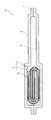
- FIG. 2 is a cross-sectional view taken along line AA in FIG. 1.
- SEM scanning electron microscope
- the present invention is characterized in that a compound containing a rare earth element and a fluorine element is fixed to the surface of the lithium transition metal composite oxide, and the average particle diameter of the compound is 1 nm or more and 100 nm or less. If it is the said structure, since the side reaction with electrolyte solution and lithium transition metal complex oxide can be suppressed (the gas generation resulting from a side reaction can also be suppressed), charge storage characteristics (especially continuous charge characteristics at high temperature) and Battery characteristics such as cycle characteristics can be dramatically improved.
- the difference from the case where a compound containing an element other than a rare earth element and a fluorine element is fixed to the surface of the lithium transition metal composite oxide is considered to occur for the following reason.
- compounds containing elements other than rare earth elements and fluorine elements are fixed, the effects of transition metals (included in lithium transition metal composite oxides) that activate the decomposition reaction of the electrolyte are suppressed. (Ie, the catalytic properties of the lithium transition metal composite oxide are not lowered).
- the compound of the present invention when the compound of the present invention is fixed, the influence of the transition metal can be suppressed (that is, the catalytic properties of the lithium transition metal composite oxide are reduced).
- the reason why the average particle size of the above compound is regulated to 1 nm or more and 100 nm or less is as follows. If the average particle size of the compound exceeds 100 nm, the compound is too large and inhibits lithium migration over a wide range. In addition, even if the volume of one compound is increased, the fixing area with the lithium transition metal composite oxide does not increase so much, so if the fixing amount is the same, the larger the average particle diameter of the compound, the more the decomposition of the electrolyte solution The effect of suppressing side reactions such as is difficult to exert. In order to suppress this side reaction, an excessive amount of compound may be added. However, if an excessive amount of compound is added, the compound has poor electron conductivity, which causes a decrease in battery output.
- the average particle size of the compound is 100 nm or less, inhibition of lithium migration can be suppressed.
- side reactions such as decomposition of the electrolytic solution can be suppressed without adding an excessive amount of compound, so the electrolytic solution and the lithium transition metal composite oxide can be more effectively produced without causing a decrease in battery output. Can be suppressed.
- the average particle size of the above compound is restricted to 1 nm or more when the average particle size is less than 1 nm, the surface of the lithium transition metal composite oxide is excessively covered with a compound that is not directly involved in the charge / discharge reaction. This is because there is a possibility that the discharge performance may be deteriorated.
- the average particle size of the compound is more preferably 10 nm or more and 80 nm or less, and particularly preferably 10 nm or more and 50 nm or less.
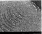
- the said average particle diameter is a value when observed with a scanning electron microscope (SEM).
- Examples of the compound containing the rare earth element and the fluorine element include trifluorides such as erbium fluoride, lanthanum fluoride, neodymium fluoride, samarium fluoride, yttrium fluoride, and ytterbium fluoride, and 3 fluorides such as cerium fluoride. Examples thereof include compounds obtained as both fluoride and tetrafluoride. In addition, these fluorides may be hydrated or partially include hydroxide, oxyhydroxide, or oxide.
- the compound containing the fluorine element and the rare earth element is preferably erbium fluoride. This is because erbium can sufficiently exhibit the above-described effects.
- the ratio of the compound containing the fluorine element and the rare earth element to the lithium transition metal composite oxide is preferably 0.01% by mass or more and 0.3% by mass or less in terms of the rare earth element. More preferably, it is 0.05 mass% or more and 0.2 mass% or less, and 0.05 mass% or more and less than 0.1 mass% among them. If the ratio is less than 0.01% by mass, the amount of the compound adhering to the surface of the lithium transition metal composite oxide becomes too small to obtain a sufficient effect, while the ratio is preferably not more than 0.001%. This is because when the amount exceeds 3% by mass, the output of the battery is reduced because the compound has poor electron conductivity.
- an aqueous solution in which a compound containing a rare earth element is dissolved in a suspension containing a water-soluble compound containing fluorine and a lithium transition metal composite oxide is added to the surface of the lithium transition metal composite oxide.
- a compound containing a fluorine element and a rare earth element is fixed.
- the lithium transition metal composite oxide and the compound containing the rare earth element are directly combined. Not mixed (that is, a lithium transition metal composite oxide and a compound containing a rare earth element are mixed in a state where a compound containing water-soluble fluorine exists). Therefore, it is possible to suppress the occurrence of a problem that a compound (hydroxide such as erbium hydroxide) other than a compound containing a rare earth element and a fluorine element is first precipitated due to an increase in pH. As a result, a compound containing a rare earth element and a fluorine element is reliably generated.
- the pH of the suspension is desirably 4 or more and 12 or less. This is because when the pH is less than 4, the lithium transition metal composite oxide may be dissolved. On the other hand, if the pH exceeds 12, impurities such as rare earth hydroxide may be generated when an aqueous solution in which a compound containing a rare earth element is dissolved is added.
- the pH can be adjusted using an acidic or basic aqueous solution.
- Examples of the compound containing fluorine include ammonium fluoride.
- the amount of the fluorine-containing compound is preferably regulated to 3 to 10 mol based on the valence (that is, the reaction amount) that the rare earth can take with respect to 1 mol of the compound containing the rare earth element. This is because if the amount of the compound containing fluorine is less than the number of moles of the valence that the rare earth can take, the amount of fluorine is insufficient and the compound containing the rare earth element and the fluorine element may not be sufficiently produced. On the other hand, when the addition amount of the compound containing fluorine exceeds 10 mol, the addition amount of the compound is too large and waste occurs.
- Examples of the compound containing rare earth elements include sulfate, nitrate, chloride, acetate, oxalate and the like.
- the positive electrode active material manufactured as described above may be heat-treated in an oxidizing atmosphere, a reducing atmosphere, or a reduced pressure state after manufacturing. In this heat treatment, if the heat treatment temperature exceeds 500 ° C., the compound containing the rare earth element and the fluorine element fixed to the surface of the lithium transition metal composite oxide is decomposed or the compound is agglomerated as the temperature rises. In addition, the compound diffuses into the lithium transition metal composite oxide. When such a thing arises, the effect which suppresses reaction with electrolyte solution and a positive electrode active material may fall. Therefore, in the case of heat treatment, the treatment temperature is desirably less than 500 ° C.
- a positive electrode for a non-aqueous electrolyte secondary battery comprising the positive electrode active material for a non-aqueous electrolyte secondary battery described above, a conductive agent, and a binder.
- a non-aqueous electrolyte secondary battery comprising such a positive electrode, a negative electrode, and a non-aqueous electrolyte.
- the negative electrode active material contained in the negative electrode preferably contains at least one selected from the group consisting of carbon particles, silicon particles, and silicon alloy particles. Since the charge / discharge potential of the carbon particles is close to the oxidation-reduction potential of metallic lithium, a side reaction between carbon and the electrolytic solution tends to occur on the surface of the carbon particles during the initial charge / discharge. On the other hand, although silicon particles and silicon alloy particles have a higher charge / discharge potential than carbon, they have a large expansion / contraction due to charge / discharge, and the negative electrode active material breaks electrochemically due to the volume change during the charge / discharge cycle. An active new surface (which tends to react with the electrolyte) is generated. As a result, during the charge / discharge cycle, a side reaction between the electrolytic solution and silicon particles or the like occurs remarkably on the new surface.
- a decomposition product is generated by a side reaction between the electrolytic solution and the negative electrode active material, and this decomposition product repeatedly moves to the positive electrode. For this reason, the decomposition product reacts with the lithium transition metal composite oxide on the surface of the positive electrode to accelerate the deterioration of the positive electrode.
- a compound containing a rare earth element and a fluorine element is fixed to the surface of the lithium transition metal composite oxide, such a reaction can be suppressed.
- the lithium transition metal composite oxide in the positive electrode active material of the present invention contains a transition metal such as cobalt, nickel, and manganese.
- a transition metal such as cobalt, nickel, and manganese.
- lithium cobalt oxide, Ni—Co—Mn lithium composite oxide, Ni—Mn—Al lithium composite oxide, Ni—Co—Al lithium composite oxide, Co—Mn lithium composite oxide And oxoacid salts of transition metals including iron, manganese, etc. represented by LiMPO 4 , Li 2 MSiO 4 , LiMBO 3 , where M is selected from Fe, Mn, Co, Ni). These may be used alone or in combination.
- the lithium-containing transition metal composite oxide may contain a substance such as Al, Mg, Ti, Zr or the like, or may be contained in the grain boundary.
- a compound such as Al, Mg, Ti, or Zr may be fixed to the surface. This is because even if these compounds are fixed, contact between the electrolytic solution and the positive electrode active material can be suppressed.
- the molar ratio of nickel, cobalt and manganese is 1: 1: 1, 5: 3: 2, 5: 2: 3, 6: 2: 2, 7: 1: 2, 7: 2: 1, and the like can be used, but in particular, a material having a higher proportion of nickel or cobalt than manganese is used so that the positive electrode capacity can be increased. It is preferable.
- the solvent of the non-aqueous electrolyte used in the present invention is not limited, and a solvent conventionally used for non-aqueous electrolyte secondary batteries can be used.
- cyclic carbonates such as ethylene carbonate, propylene carbonate, butylene carbonate, vinylene carbonate, chain carbonates such as dimethyl carbonate, methyl ethyl carbonate, diethyl carbonate, methyl acetate, ethyl acetate, propyl acetate, methyl propionate, propionic acid
- esters such as ethyl and ⁇ -butyrolactone
- compounds containing sulfone groups such as propane sultone, 1,2-dimethoxyethane, 1,2-diethoxyethane, tetrahydrofuran, 1,2-dioxane, 1,4 -Compounds containing ethers such as dioxane and 2-methyltetrahydrofuran, butyronitrile, valer
- a solvent in which a part of these H is substituted with F is preferably used. Further, these can be used alone or in combination, and a solvent in which a cyclic carbonate and a chain carbonate are combined, and a solvent in which a compound containing a small amount of nitrile or a compound containing ether is combined is preferable. .
- the concentration of the solute is not particularly limited, but is preferably 0.8 to 1.5 mol per liter of the electrolyte.
- a conventionally used negative electrode can be used, and in particular, a carbon material capable of occluding and releasing lithium, a metal that can be alloyed with lithium, or an alloy compound containing the metal Is mentioned.
- the carbon material natural graphite, non-graphitizable carbon, graphite such as artificial graphite, coke, etc. can be used, and examples of the alloy compound include those containing at least one metal that can be alloyed with lithium. It is done.
- silicon or tin is preferable as an element capable of forming an alloy with lithium, and silicon oxide, tin oxide, or the like in which these are combined with oxygen can also be used.
- a mixture of the above carbon material and a compound of silicon or tin can be used.
- a negative electrode material having a higher charge / discharge potential than lithium carbon such as lithium titanate can be used.
- a layer made of an inorganic filler that has been conventionally used can be formed.
- the filler it is possible to use oxides or phosphate compounds using titanium, aluminum, silicon, magnesium, etc., which have been used conventionally, or those whose surfaces are treated with hydroxide or the like.
- the filler layer can be formed by directly applying a filler-containing slurry to a positive electrode, a negative electrode, or a separator, or by attaching a sheet formed of a filler to the positive electrode, the negative electrode, or the separator. it can.
- the separator conventionally used can be used. Specifically, not only a separator made of polyethylene, but also a material in which a layer made of polypropylene is formed on the surface of a polyethylene layer, or a material in which a resin such as an aramid resin is applied to the surface of a polyethylene separator is used. Also good.
- the positive electrode active material, the positive electrode, and the battery for the nonaqueous electrolyte secondary battery will be described below.
- the positive electrode for nonaqueous electrolyte secondary batteries in this invention, a positive electrode, and a battery are not limited to the following Example, In the range which does not change the summary, it can implement suitably.
- Example 1 [Production of positive electrode] (1) Production of positive electrode active material First, 1000 g of lithium cobalt oxide particles containing 1.0 mol% of Mg and Al in a solid solution of lithium cobalt oxide and 0.04 mol% of Zr were prepared. The particles were added to 3.0 L of pure water and stirred to prepare a suspension in which lithium cobaltate was dispersed. Next, an aqueous solution in which 1 g of ammonium fluoride was dissolved in 100 mL of pure water was added to this suspension.
- the obtained powder is dried at 120 ° C., and the surface of the lithium cobalt oxide contains fluorine and erbium.
- a positive electrode active material to which a compound (hereinafter sometimes simply referred to as an erbium compound) was fixed was obtained. Thereafter, the obtained positive electrode active material powder was heat-treated in air at 300 ° C. for 5 hours.
- the erbium compound was uniformly dispersed and fixed on the surface of the lithium cobalt oxide,
- the average particle diameter of the erbium compound was found to be 1 nm or more and 100 nm or less.
- the fixed amount of the erbium compound was measured by ICP, it was 0.068 mass% with respect to lithium cobaltate in terms of erbium element.
- a polycrystalline silicon lump was produced by a thermal reduction method. Specifically, the silicon core installed in the metal reaction furnace (reduction furnace) is heated by heating to 800 ° C., and purified with the purified high purity monosilane (SiH 4 ) gas vapor. By flowing a gas mixed with hydrogen, polycrystalline silicon was deposited on the surface of the silicon core, thereby producing a polycrystalline silicon lump produced in a thick rod shape.
- the polycrystalline silicon lump was pulverized and classified to prepare polycrystalline silicon particles (negative electrode active material particles) having a purity of 99%.
- the crystallite size was 32 nm, and the median diameter was 10 ⁇ m.
- the crystallite size was calculated by the Scherrer equation using the half width of the silicon (111) peak in powder X-ray diffraction.
- the median diameter was defined as the diameter at which the cumulative volume reached 50% in the particle size distribution measurement by the laser diffraction method.
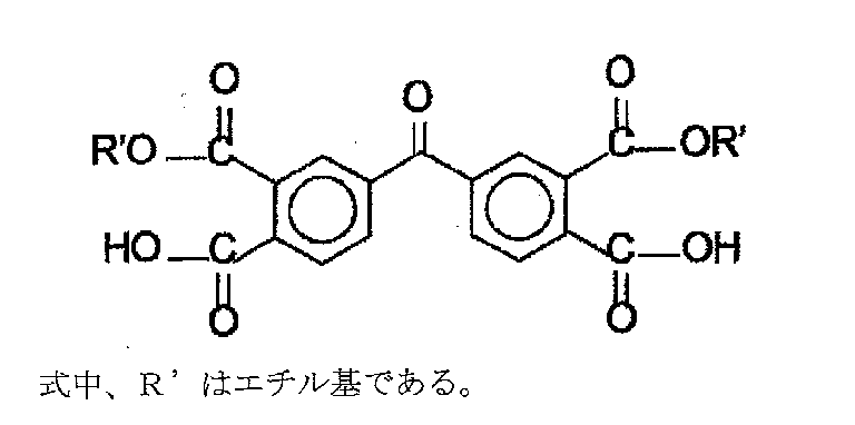
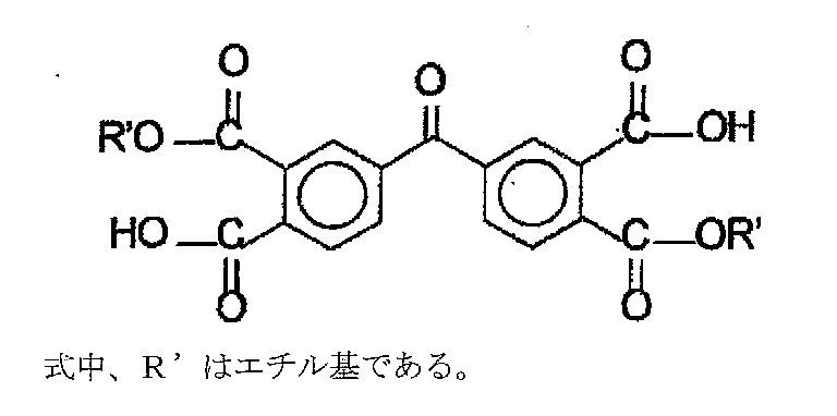
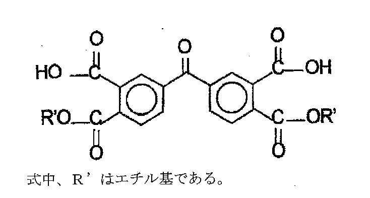
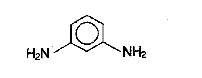
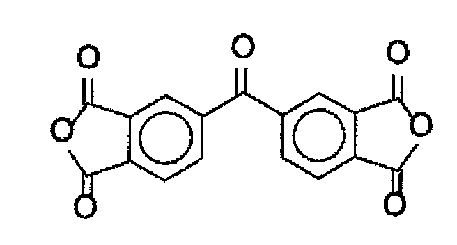
- the precursor varnish of the polyimide resin includes 3,3 ′, 4,4′-benzophenone tetracarboxylic acid diethyl ester represented by the following chemical formula 2, chemical formula 3, and chemical formula 4, and m-phenylene represented by chemical formula 5 below. It can be made from diamine. Further, 3,3 ′, 4,4′-benzophenone tetracarboxylic acid diethyl ester represented by Chemical Formula 2, Chemical Formula 3, and Chemical Formula 4 is a 3,3 ′, 4,4′-benzophenone tetracarboxylic acid diester represented by Chemical Formula 6 below. It can be prepared by reacting 2 equivalents of ethanol with anhydride in the presence of NMP.
- a copper alloy foil having a thickness of 18 ⁇ m (C7025 alloy foil having a composition of 96.2% by mass of Cu, 3% by mass of Ni, and 0.65% by mass of Si) , Mg is 0.15% by mass), and is roughened so that the surface roughness Ra (JIS B 0601-1994) is 0.25 ⁇ m and the average peak spacing S (JIS B 0601-1994) is 1.0 ⁇ m. What was done was used.
- the negative electrode mixture slurry was applied to both surfaces of the negative electrode current collector in air at 25 ° C., dried in air at 120 ° C., and then rolled in air at 25 ° C.
- the obtained product was cut into a rectangle having a length of 380 mm and a width of 52 mm, and then heat-treated in an argon atmosphere at 400 ° C. for 10 hours to produce a negative electrode in which a negative electrode active material layer was formed on the surface of the negative electrode current collector.
- the packing density of the negative electrode was 1.6 g / cc, and a nickel plate as a negative electrode current collecting tab was connected to the end of the negative electrode.
- a lead terminal is attached to each of the positive and negative electrodes, a separator is disposed between the two electrodes and wound in a spiral shape, and then a spiral electrode body is produced by pulling out the winding core, and the electrode body is further crushed, A flat electrode body was obtained.
- the flat electrode body and the non-aqueous electrolyte are placed between two aluminum laminate exterior bodies and sealed at 25 ° C. under a CO 2 atmosphere of 1 atm.
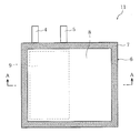
- a flat nonaqueous electrolyte secondary battery 11 having the structure shown in FIG. 1 and FIG. 2 was produced.
- the size of the secondary battery 11 is 3.6 mm thick ⁇ 70 mm wide ⁇ 62 mm high, and the discharge capacity when the secondary battery is charged to 4.35V and discharged to 2.75V. Was 850 mAh.
- the specific structure of the non-aqueous electrolyte secondary battery 11 is such that a positive electrode 1 and a negative electrode 2 are arranged to face each other with a separator 3 therebetween.
- a flat electrode body 9 composed of 1 and 2 and the separator 3 is impregnated with a non-aqueous electrolyte.
- the positive electrode 1 and the negative electrode 2 are connected to a positive electrode current collector tab 4 and a negative electrode current collector tab 5, respectively, and have a structure capable of charging and discharging as a secondary battery.
- the electrode body 9 is arrange
- reference numeral 8 denotes a spare chamber for minimizing the influence of the gas generated by the decomposition of the electrolyte etc. on the charge / discharge.
- the battery produced as described above is hereinafter referred to as battery A1.
- Example 2 When preparing the positive electrode active material, instead of a solution in which erbium nitrate pentahydrate was dissolved in 200 mL of pure water, 1.77 g of lanthanum nitrate hexahydrate was added to 200 mL of pure water as a solution to be added to the suspension.
- a positive electrode active material was produced in the same manner as in Example 1 except that the solution dissolved in was used.
- a compound containing lanthanum and a fluorine element hereinafter sometimes simply referred to as a lanthanum compound
- the ratio of the lanthanum compound to lithium cobalt oxide was 0.057% by mass in terms of lanthanum element (defined as being equivalent to the case of Example 1 above in terms of metal element).
- the battery thus produced is hereinafter referred to as battery A2.
- Example 1 The same as Example 1 except that the erbium compound is not fixed to the lithium cobaltate (that is, the positive electrode active material is composed only of lithium cobaltate) and the positive electrode active material not subjected to heat treatment is used. Thus, a battery was produced. The battery thus produced is hereinafter referred to as battery Z1.
- Example 2 A battery was produced in the same manner as in Example 1 except that, when producing the positive electrode active material, 200 mL of pure water was added instead of the solution in which erbium nitrate pentahydrate was dissolved.
- the battery thus produced is hereinafter referred to as battery Z2.
- the positive electrode active material was prepared in the same manner as in Example 1 above, except that 200 mL of a solution in which 1.53 g of aluminum nitrate nonahydrate was dissolved was added instead of erbium nitrate pentahydrate. was made.
- a compound containing aluminum and a fluorine element hereinafter sometimes simply referred to as an aluminum compound
- the ratio of the aluminum compound to lithium cobaltate was 0.011% by mass in terms of aluminum element (defined as being equivalent to the case of Example 1 above in terms of metal element).
- the battery thus produced is hereinafter referred to as battery Z3.
- Comparative Example 4 A battery was fabricated in the same manner as in Comparative Example 1 except that erbium fluoride powder having an average particle diameter of 500 nm was mixed with lithium cobaltate powder. The ratio of erbium fluoride to lithium cobaltate was 0.068% by mass in terms of erbium element. The battery thus produced is hereinafter referred to as battery Z4.
- Capacity remaining rate (%) (first discharge capacity after continuous charge test / discharge capacity before continuous charge test) ⁇ 100 (1)
- the batteries A1 and A2 are superior to the batteries Z1 to Z4 in cycle characteristics (number of cycles) and continuous charge characteristics (capacity remaining rate) at high temperatures.
- the continuous charge characteristic at high temperature mainly represents the degree of gas generation due to the deterioration of the positive electrode accompanying the side reaction between the positive electrode and the electrolyte and the side reaction.
- the batteries A1, A2, and Z1 to Z4 are provided with spare chambers for storing gas in order to reduce the influence of gas generation due to side reactions. Thereby, it becomes possible to investigate mainly the deterioration of the positive electrode due to the side reaction between the positive electrode and the electrolytic solution.
- the battery Z3 in which the aluminum compound is fixed to the surface of lithium cobaltate is the battery Z1 in which the compound is not fixed to the surface of lithium cobaltate, or erbium fluoride.
- the capacity remaining rate is slightly higher.
- the batteries A1 and A2 in which rare earth compounds such as erbium compounds and lanthanum compounds are fixed to the surface of the lithium cobalt oxide have capacity remaining even when compared with the batteries Z1 and Z4 as well as the batteries Z3. It is recognized that the rate is much higher.
- the above results are considered to be due to the ability of the battery A1 and the battery A2 to suppress the deterioration of the positive electrode due to the side reaction between the positive electrode and the electrolyte during the continuous charge test.
- the capacity remaining rate of the battery A1 and the battery A2 is higher than that of the battery Z3 even though the compound is fixed to the surface of the lithium cobalt oxide. This is probably due to the reason shown.
- the influence of the transition metal contained in the lithium transition metal composite oxide that activates the decomposition reaction of the electrolytic solution cannot be suppressed (that is, And the catalytic properties of the lithium transition metal composite oxide do not decrease).
- a rare earth compound such as an erbium compound or a lanthanum compound adheres to the surface of lithium cobaltate as in the battery A1 and the battery A2
- the influence of the transition metal can be suppressed (that is, lithium transition). This is because the catalytic properties of the metal composite oxide are reduced.
- the battery A1 and the battery A2 are compared, a more excellent effect is obtained when the erbium compound is fixed to the surface.
- the cycle characteristics indicate that the decomposition product generated by the side reaction between the negative electrode and the electrolyte moves to the positive electrode to accelerate the deterioration of the positive electrode, thereby reducing the discharge capacity.
- the degree of expansion and contraction associated with charge / discharge is large, and the negative electrode active material cracks with the volume change during the cycle and is electrochemically active (electrolytic solution and side reaction). A new surface is generated, and this causes a more significant side reaction between the electrolyte and the negative electrode active material.
- the decomposition product by the said side reaction repeatedly moves to a positive electrode, it reacts with a lithium transition metal complex oxide on the positive electrode surface, and accelerates deterioration of a positive electrode.
- the battery Z3 is superior in cycle characteristics compared to the battery Z1 and the battery Z4, but the battery A1 and the battery A2 have the battery Z1 and the battery Z4.
- the cycle characteristics are remarkably excellent. This is because in batteries Z1, Z3, and Z4, the influence of decomposition products generated from the negative electrode cannot be suppressed, or even if it can be suppressed, it is insufficient. In batteries A1 and A2, decomposition generated from the negative electrode This is because the influence of the product can be sufficiently suppressed.
- the fluorine compound was added like the battery Z2, when it produces without adding the compound containing an erbium element, cycling characteristics and a high temperature continuous charge characteristic are all the same as the battery Z1. Therefore, in the case of the battery Z2, in the step of producing the positive electrode active material, a compound capable of suppressing the deterioration of the positive electrode and the influence of the decomposition product generated from the negative electrode was not generated on the surface of the lithium cobalt oxide. Conceivable.
- Example 1 is the same as Example 1 of the first example except that the negative electrode, the non-aqueous electrolyte, and the battery were prepared as described below. That is, the configuration of the positive electrode is the same as that of Example 1 of the first example.
- the battery thus produced is hereinafter referred to as battery B1.
- Graphite as the negative electrode active material, SBR (styrene butadiene rubber) as the pressure-sensitive adhesive, and CMC (carboxyl methylcellulose) as the thickener were weighed so that the mass ratio was 98: 1: 1.
- a negative electrode active material slurry was prepared by kneading in an aqueous solution. Next, a predetermined amount of the negative electrode active material slurry was applied to both sides of a copper foil as a negative electrode current collector, and further dried, and then rolled to a packing density of 1.7 g / cc to prepare a negative electrode. .
- a lead terminal is attached to each of the positive and negative electrodes, a separator is disposed between the two electrodes and wound in a spiral shape, and then a spiral electrode body is produced by pulling out the winding core, and the electrode body is further crushed, A flat electrode body was obtained.
- the flat electrode body and the non-aqueous electrolyte are placed between two aluminum laminate exterior bodies and sealed in an argon atmosphere at 25 ° C. and 1 atm.
- the flat type nonaqueous electrolyte secondary battery 11 which has a structure shown by FIG. 2 was produced.
- the secondary battery 11 has a thickness of 3.6 mm ⁇ width 70 mm ⁇ height 62 mm, and the discharge capacity when the secondary battery is charged to 4.40 V and discharged to 2.75 V. Was 750 mAh.
- Example 2 The battery was manufactured in the same manner as in Example 1 of the above second example except that 1.56 g of yttrium nitrate hexahydrate was used instead of 1.81 g of erbium nitrate pentahydrate at the time of producing the positive electrode active material. was made.
- SEM scanning electron microscope
- a compound containing yttrium and fluorine was uniformly dispersed and fixed on the surface of lithium cobaltate, and The average particle size of the compound was found to be 1 nm or more and 100 nm or less.
- battery B2 when the amount of the fixed compound was measured by ICP, it was 0.036% by mass in terms of yttrium element with respect to lithium cobaltate (in the case of Example 1 of the second example in terms of metal element). And equimolar).
- the battery thus produced is hereinafter referred to as battery B2.
- Example 3 A battery was prepared in the same manner as in Example 1 of the second example except that 1.77 g of lanthanum nitrate hexahydrate was used instead of 1.81 g of erbium nitrate pentahydrate when the positive electrode active material was produced. Was made. In addition, when the obtained positive electrode active material was observed with a scanning electron microscope (SEM), a compound containing lanthanum and fluorine was uniformly dispersed and fixed on the surface of the lithium cobalt oxide, and The average particle size of the compound was found to be 1 nm or more and 100 nm or less.
- SEM scanning electron microscope
- battery B3 when the amount of the fixed compound was measured by ICP, it was 0.057% by mass in terms of lanthanum element with respect to lithium cobaltate (in the case of Example 1 of the second example in terms of metal element). And equimolar).
- the battery thus produced is hereinafter referred to as battery B3.
- Example 4 A battery was prepared in the same manner as in Example 1 of the second example except that 1.79 g of neodymium nitrate hexahydrate was used instead of 1.81 g of erbium nitrate pentahydrate when the positive electrode active material was produced. Was made. In addition, when the obtained positive electrode active material was observed with a scanning electron microscope (SEM), a compound containing neodymium and fluorine was uniformly dispersed and fixed on the surface of the lithium cobalt oxide, and The average particle size of the compound was found to be 1 nm or more and 100 nm or less.
- SEM scanning electron microscope
- battery B4 when the fixed amount of the compound was measured by ICP, it was 0.059% by mass in terms of neodymium element with respect to lithium cobaltate (in the case of Example 1 of the second example in terms of metal element). And equimolar).
- the battery thus produced is hereinafter referred to as battery B4.
- Example 5 A battery was prepared in the same manner as in Example 1 of the second example except that 1.82 g of samarium nitrate hexahydrate was used instead of 1.81 g of erbium nitrate pentahydrate when the positive electrode active material was produced. Was made. In addition, when the obtained positive electrode active material was observed with a scanning electron microscope (SEM), a compound containing samarium and fluorine was uniformly dispersed and fixed on the surface of lithium cobaltate, and The average particle size of the compound was found to be 1 nm or more and 100 nm or less.
- SEM scanning electron microscope
- battery B5 when the amount of the fixed compound was measured by ICP, it was 0.061% by mass in terms of samarium element with respect to lithium cobaltate (in the case of Example 1 of the second example in terms of metal element). And equimolar).
- the battery thus produced is hereinafter referred to as battery B5.
- Example 6 A battery was prepared in the same manner as in Example 1 of the second example except that 1.69 g of ytterbium nitrate trihydrate was used instead of 1.81 g of erbium nitrate pentahydrate when the positive electrode active material was produced. Was made. In addition, when the obtained positive electrode active material was observed with a scanning electron microscope (SEM), a compound containing ytterbium and fluorine was uniformly dispersed and fixed on the surface of lithium cobaltate, and The average particle size of the compound was found to be 1 nm or more and 100 nm or less.
- SEM scanning electron microscope
- battery B6 when the adhesion amount of the compound was measured by ICP, it was 0.071% by mass in terms of ytterbium element with respect to lithium cobaltate (in the case of Example 1 of the second example in terms of metal element). And equimolar).
- the battery thus produced is hereinafter referred to as battery B6.
- the erbium compound is not fixed to the lithium cobaltate (that is, the positive electrode active material is composed only of lithium cobaltate) and the positive electrode active material not subjected to heat treatment is used.
- a battery was produced in the same manner as in Example 1. The battery thus produced is hereinafter referred to as battery Y.
- the reason is considered to be due to the following reasons. (1) If a compound containing a rare earth element and a fluorine element is fixed to the surface of lithium cobalt oxide, the contact area between the lithium transition metal composite oxide and the electrolyte is reduced. Therefore, it is possible to suppress the occurrence of an oxidative decomposition reaction of the electrolytic solution on the surface of the lithium transition metal composite oxide.
- Example 1 A battery was fabricated in the same manner as in Example 1 of the first example except that the discharge capacity of the battery was 750 mAh. The battery thus produced is hereinafter referred to as battery C1.
- Example 1 The third embodiment is carried out except that the erbium compound is not fixed to lithium cobaltate (that is, the positive electrode active material is composed only of lithium cobaltate) and the positive electrode active material not subjected to heat treatment is used.
- a battery was produced in the same manner as in Example 1. The battery thus produced is hereinafter referred to as battery X1.
- Example 2 A battery was fabricated in the same manner as in Example 1 of the second example, except that the following electrolyte was used and the discharge capacity of the battery was 750 mAh.
- LiPF 6 lithium hexafluorophosphate
- FEC fluoroethylene carbonate
- MEC methyl ethyl carbonate
- the present invention can be expected to be developed for a driving power source for mobile information terminals such as mobile phones, notebook computers, and PDAs, and a driving power source for high output such as HEV and electric tools.
Landscapes
- Chemical & Material Sciences (AREA)
- Chemical Kinetics & Catalysis (AREA)
- Electrochemistry (AREA)
- General Chemical & Material Sciences (AREA)
- Composite Materials (AREA)
- Inorganic Chemistry (AREA)
- Engineering & Computer Science (AREA)
- Manufacturing & Machinery (AREA)
- Secondary Cells (AREA)
- Battery Electrode And Active Subsutance (AREA)
Abstract
Description
(1)フッ化アルミニウム、フッ化亜鉛、フッ化リチウム等のフッ化物の金属原子を、正極活物質の重量に対して0.1~10重量%被覆する旨記載されている(下記特許文献1参照)。
上記構成であれば、電解液とリチウム遷移金属複合酸化物との副反応を抑制できる(副反応に起因するガス発生も抑制できる)ので、充電保存特性(特に、高温での連続充電特性)やサイクル特性等の電池特性を飛躍的に向上させることができる。
これに対して、本発明の化合物が固着されている場合には、上記遷移金属の影響を抑制できる(即ち、リチウム遷移金属複合酸化物の触媒性が低下する)ということに起因する。
一方、上記化合物の平均粒子径を1nm以上に規制するのは、当該平均粒子径が1nm未満になると、リチウム遷移金属複合酸化物の表面が充放電反応に直接関与はし難い化合物で過剰に覆われて、放電性能の低下を招く恐れがあるという理由による。
以上のことを考慮すれば、上記化合物の平均粒子径は10nm以上80nm以下であることがより好ましく、10nm以上50nm以下であることが特に好ましい。
尚、上記平均粒子径は、走査型電子顕微鏡(SEM)にて観察したときの値である。
エルビウムは、上述した作用効果を十分に発揮できるからである。
当該割合が0.01質量%未満ではリチウム遷移金属複合酸化物の表面に付着している化合物の量が過小となって、十分な効果を得ることができないことがある一方、当該割合が0.3質量%を超えると、化合物が電子伝導性に乏しいことに起因して、電池の出力低下を招来するからである。
上記方法であれば、リチウム遷移金属複合酸化物表面に希土類元素とフッ素元素とを含む化合物を均一に固着させることが可能であるので、電解液とリチウム遷移金属複合酸化物との副反応を抑制でき(副反応に起因するガス発生も抑制でき)、これによって、連続充電特性(特に、高温での連続充電特性)や、サイクル特性等の電池特性を向上させることができる。
尚、希土類元素を含む化合物(希土類塩)としては、硫酸塩、硝酸塩、塩化物、酢酸塩、シュウ酸塩等が例示される。
上記のように作製した正極活物質を、作製後に酸化性雰囲気、還元性雰囲気又は減圧状態の下で熱処理することがある。この熱処理において熱処理温度が500℃を超えると、温度の高温化に伴い、リチウム遷移金属複合酸化物表面に固着した希土類元素とフッ素元素とを含む化合物が分解したり、当該化合物が凝集してしまうだけでなく、当該化合物がリチウム遷移金属複合酸化物の内部に拡散してしまう。このようなことが生じると、電解液と正極活物質との反応を抑制する効果が低下することがある。したがって、熱処理する場合には、処理温度は500℃未満であることが望ましい。
炭素粒子の充放電の電位は、金属リチウムの酸化還元電位に近く低いため、初期の充放電時に炭素粒子表面で炭素と電解液との副反応が生じ易い。
一方、ケイ素粒子やケイ素合金粒子は充放電の電位が炭素よりも高いものの、充放電に伴う膨張収縮度が大きく、充放電サイクル時の体積変化に伴い負極活物質が割れて、電気化学的に活性な(電解液と反応が生じ易い)新生面が生じる。この結果、充放電サイクル中に、その新生面において、電解液とケイ素粒子等との副反応が顕著に生じる。
(1)本発明の正極活物質におけるリチウム遷移金属複合酸化物は、コバルト、ニッケル、マンガン等の遷移金属を含む。具体的には、コバルト酸リチウム、Ni-Co-Mnのリチウム複合酸化物、Ni-Mn-Alのリチウム複合酸化物、Ni-Co-Alのリチウム複合酸化物、Co-Mnのリチウム複合酸化物、鉄、マンガンなどを含む遷移金属のオキソ酸塩(LiMPO4、Li2MSiO4、LiMBO3で表され、MはFe、Mn、Co、Niから選択される)が例示される。また、これらを単独で用いてもよいし、混合して用いてもよい。
炭素材料としては、天然黒鉛や難黒鉛化性炭素、人造黒鉛等のグラファイト類、コークス類等を用いることができ、合金化合物としては、リチウムと合金化可能な金属を少なくとも1種類含むものが挙げられる。特に、リチウムと合金形成可能な元素としてはケイ素やスズであることが好ましく、これらが酸素と結合した、酸化ケイ素や酸化スズ等も用いることもできる。また、上記炭素材料とケイ素やスズの化合物とを混合したものを用いることができる。
上記の他、エネルギー密度は低下するものの、負極材料としてはチタン酸リチウム等の金属リチウムに対する充放電の電位が、炭素材料等より高いものも用いることができる。
上記フィラー層の形成は、正極、負極、或いはセパレータに、フィラー含有スラリーを直接塗布して形成する方法や、フィラーで形成したシートを、正極、負極、或いはセパレータに貼り付ける方法等を用いることができる。
第1実施例では、負極活物質にケイ素を用いた場合の効果について調べた。
(実施例1)
[正極の作製]
(1)正極活物質の作製
先ず、コバルト酸リチウムに対してMg及びAlを各1.0モル%固溶し、且つZrを0.04モル%含有したコバルト酸リチウム粒子1000gを用意し、この粒子を3.0Lの純水に添加し攪拌して、コバルト酸リチウムが分散した懸濁液を調製した。次に、この懸濁液に、100mLの純水にフッ化アンモニウム1gを溶解させた水溶液を加えた。次いで、上記懸濁液に、硝酸エルビウム5水和物1.81g(エルビウム元素換算で、0.068質量%)が200mLの純水に溶解された溶液を加えた。尚、上記エルビウムと上記フッ素とのモル比は、1:6.7となるように調整されている。また、コバルト酸リチウムとフッ化アンモニウムとを含む懸濁液のpHを常時7に調整するため、10質量%の硝酸水溶液、或いは、10質量%の水酸化ナトリウム水溶液を適宜加えた。
上記正極活物質粉末と、正極導電剤としてのカーボンブラック(アセチレンブラック)粉末(平均粒径:40nm)と、正極バインダー(結着剤)としてのポリフッ化ビニリデン(PVdF)とを、質量比で95:2.5:2.5の割合になるように、NMP溶液中で混練し正極合剤スラリーを調製した。最後に、この正極合剤スラリーを、アルミニウム箔から成る正極集電体の両面に塗布、乾燥した後、圧延ローラにより圧延することにより、正極集電体の両面に正極合剤層が形成された正極を作製した。尚、当該正極の充填密度は、3.7g/ccとした。
(1)負極活物質の作製
先ず、熱還元法により、多結晶ケイ素塊を作製した。具体的には、金属反応炉(還元炉)内に設置されたケイ素芯を通電加熱して800℃まで上昇させておき、これに精製された高純度モノシラン(SiH4)ガスの蒸気と精製された水素とを混合したガスを流すことで、ケイ素芯の表面に多結晶ケイ素を析出させ、これにより、太い棒状に生成された多結晶ケイ素塊を作製した。
分散媒としてのNMPに、上記負極活物質粉末と、負極導電剤としての平均粒径3.5μmの黒鉛粉末と、負極バインダーとしての下記化1(nは1以上の整数)で示される分子構造を有しガラス転移温度300℃である熱可塑性ポリイミド樹脂の前駆体のワニス(溶媒:NMP、濃度:熱処理によるポリマー化+イミド化後のポリイミド樹脂の量で47質量%)とを、負極活物質粉末と負極導電剤粉末とイミド化後のポリイミド樹脂との質量比が89.5:3.7:6.8となるように混合し、負極合剤スラリーを調製した。

負極集電体として、厚さ18μmの銅合金箔(C7025合金箔であり、組成は、Cuが96.2質量%、Niが3質量%、Siが0.65質量%、Mgが0.15質量%)の両面を、表面粗さRa(JIS B 0601-1994)が0.25μm、平均山間隔S(JIS B 0601-1994)が1.0μmとなるように粗化したものを用いた。この負極集電体の両面に上記負極合剤スラリーを、25℃空気中で塗布し、120℃空気中で乾燥後、25℃空気中で圧延した。得られたものを、長さ380mm、幅52mmの長方形に切り抜いた後、アルゴン雰囲気下で400℃、10時間熱処理し、負極集電体の表面に負極活物質層が形成された負極を作製した。なお、負極の充填密度は、1.6g/ccとし、負極の端部には、負極集電タブとしてのニッケル板を接続した。
フルオロエチレンカーボネート(FEC)とメチルエチルカーボネート(MEC)とを体積比20:80で混合した溶媒に対し、六フッ化リン酸リチウム(LiPF6)を1モル/リットル溶解させた後、この溶液に対して、0.4質量%の二酸化炭素ガスを溶存させ、非水電解液を調製した。
上記正負極それぞれにリード端子を取り付け、これら両極間にセパレータを配置して渦巻き状に巻回した後、巻き芯を引き抜いて渦巻状の電極体を作製し、更にこの電極体を押し潰して、扁平型の電極体を得た。次に、この扁平型の電極体と上記非水電解液とを、25℃、1気圧のCO2雰囲気下で、2枚のアルミニウムラミネート製の外装体間に配置し、封口することにより、図1及び図2に示される構造を有する扁平型の非水電解質二次電池11を作製した。尚、当該二次電池11のサイズは、厚さ3.6mm×幅70mm×高さ62mmであり、また、当該二次電池を4.35Vまで充電し、2.75Vまで放電したときの放電容量は850mAhであった。
以上のようにして作製した電池を、以下、電池A1と称する。
正極活物質を作製する際、懸濁液に加える溶液として、硝酸エルビウム5水和物が200mLの純水に溶解された溶液に代えて、硝酸ランタン6水和物1.77gが200mLの純水に溶解された溶液を用いたこと以外は、上記実施例1と同様にして正極活物質を作製した。尚、このようにして作製した正極活物質では、コバルト酸リチウムの表面にランタンとフッ素元素を含む化合物(以下、単に、ランタン化合物と称することがある)が固着しているものと考えられ、当該ランタン化合物のコバルト酸リチウムに対する割合は、ランタン元素換算で、0.057質量%であった(金属元素換算で、上記実施例1の場合と等モルとなるように規定している)。
このようにして作製した電池を、以下、電池A2と称する。
上記コバルト酸リチウムにエルビウム化合物を固着させず(即ち、正極活物質はコバルト酸リチウムのみから構成されている)、且つ、熱処理を施さない正極活物質を用いた他は、上記実施例1と同様にして電池を作製した。
このようにして作製した電池を、以下、電池Z1と称する。
正極活物質を作製する際、硝酸エルビウム5水和物が溶解された溶液に代えて純水200mLを加えたこと以外は、上記実施例1と同様にして電池を作製した。
このようにして作製した電池を、以下、電池Z2と称する。
正極活物質を作製する際、硝酸エルビウム5水和物に代えて硝酸アルミニウム9水和物1.53gが溶解された溶液200mLを加えたこと以外は、上記実施例1と同様にして正極活物質を作製した。尚、このようにして作製した正極活物質では、コバルト酸リチウムの表面にアルミニウムとフッ素元素を含む化合物(以下、単に、アルミニウム化合物と称することがある)が固着しているものと考えられ、当該アルミニウム化合物のコバルト酸リチウムに対する割合は、アルミニウム元素換算で、0.011質量%であった(金属元素換算で、上記実施例1の場合と等モルとなるように規定している)。
このようにして作製した電池を、以下、電池Z3と称する。
500nmの平均粒子径のフッ化エルビウム粉末を、コバルト酸リチウム粉末と混合したこと以外は、比較例1と同様にして電池を作製した。フッ化エルビウムのコバルト酸リチウムに対する割合は、エルビウム元素換算で、0.068質量%であった。
このようにして作製した電池を、以下、電池Z4と称する。
上記電池A1、A2、Z1~Z4を下記の条件で充放電して、各電池のサイクル特性と高温連続充電特性とを調べたので、その結果を表1に示す。
〔サイクル特性調査時の充放電条件〕
・充電条件
1.0It(850mA)の電流で電池電圧4.35Vまで定電流充電を行った後、定電圧で電流が0.05It(42.5mA)になるまで充電するという条件。
1.0It(850mA)の電流で電池電圧2.75Vまで定電流放電を行うという条件。
・休止
充電と放電との間隔は10分とした。
サイクル特性の評価は、上記充電、休止、放電、休止を順に繰り返し行い、所定サイクル目の放電容量が、1サイクル目の放電容量の80%となったときを電池寿命とした。
尚、サイクル特性試験時の温度は、25℃±5℃である。
上記サイクル特性調査時の充放電条件と同様の条件で充放電を1回行って、放電容量(連続充電試験前の放電容量)を測定した。次に、各電池を60℃の恒温槽で1時間放置した後、60℃の環境のまま、1.0It(850mA)の定電流で電池電圧4.35Vまで充電し、さらに4.35Vの定電圧で充電を行った。60℃でのトータル充電時間が48時間に達したときに、60℃の恒温槽から電池を取り出した。その後、室温にまで冷却してから、放電容量(連続充電試験後1回目のの放電容量)を測定し、連続充電試験前後の放電容量から、下記(1)式を用いて、容量残存率を算出した。
容量残存率(%)=(連続充電試験後1回目の放電容量/連続充電試験前の放電容量)×100・・・(1)
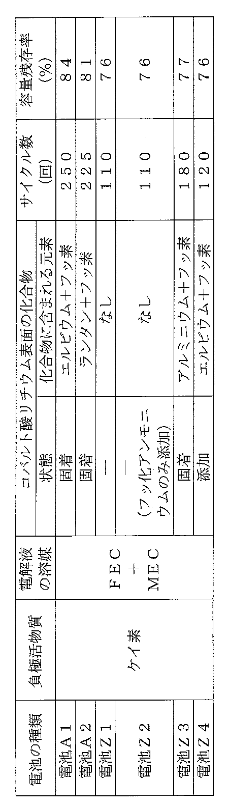
ここで、高温での連続充電特性は、主として、正極と電解液との副反応に伴う正極の劣化と副反応によるガス発生の程度を表している。但し、副反応によるガス発生による影響を低減すべく、上述したように、電池A1、A2、Z1~Z4にはガスを貯留するための予備室が設けられている。これにより、主として、正極と電解液との副反応に伴う正極の劣化について調べることが可能となる。
第2実施例では、負極活物質に炭素材料(黒鉛)を用いた場合にも、同様の効果を有するか否か、及び、正極活物質の表面に固着された化合物中に含まれる希土類元素として、エルビウム、ランタン以外のものを用いた場合にも、同様の効果を有するか否かについても調べた。
(実施例1)
下記のようにして、負極の作製と、非水電解液の調製と、電池の作製とを行った以外は、上記第1実施例の実施例1と同様である。即ち、正極の構成は、上記第1実施例の実施例1と全て同様である。
このようにして作製した電池を、以下、電池B1と称する。
負極活物質としての黒鉛と、粘着剤としてのSBR(スチレンブタジエンゴム)と、増粘剤としてのCMC(カルボキシルメチルセルロース)とが、質量比98:1:1となるように秤量した後、これらを水溶液中で混練して負極活物質スラリーを調製した。次に、負極集電体としての銅箔の両面に上記負極活物質スラリーを所定量塗布し、更に、乾燥した後、充填密度が1.7g/ccとなるように圧延して負極を作製した。
エチレンカーボネート(EC)とメチルエチルカーボネート(MEC)とを体積比20:80で混合した溶媒に対し、六フッ化リン酸リチウム(LiPF6)を1モル/リットル溶解させ、非水電解液を調製した。
上記正負極それぞれにリード端子を取り付け、これら両極間にセパレータを配置して渦巻き状に巻回した後、巻き芯を引き抜いて渦巻状の電極体を作製し、更にこの電極体を押し潰して、扁平型の電極体を得た。次に、この扁平型の電極体と上記非水電解液とを、25℃、1気圧のアルゴン雰囲気下で、2枚のアルミニウムラミネート製の外装体間に配置し、封口することにより、図1及び図2に示される構造を有する扁平型の非水電解質二次電池11を作製した。尚、当該二次電池11のサイズは、厚さ3.6mm×幅70mm×高さ62mmであり、また、当該二次電池を4.40Vまで充電し、2.75Vまで放電したときの放電容量は750mAhであった。
正極活物質の作製時に、硝酸エルビウム5水和物1.81gに代えて、硝酸イットリウム6水和物1.56gを用いたこと以外は、上記第2実施例の実施例1と同様にして電池を作製した。尚、得られた正極活物質について、走査型電子顕微鏡(SEM)にて観察したところ、コバルト酸リチウムの表面に、イットリウムとフッ素とを含む化合物が均一に分散して固着しており、且つ、当該化合物の平均粒子径は1nm以上100nm以下であることが認められた。また、当該化合物の固着量をICPにより測定したところ、イットリウム元素換算で、コバルト酸リチウムに対して0.036質量%であった(金属元素換算で、上記第2実施例の実施例1の場合と等モルとなるように規定している)。
このようにして作製した電池を、以下、電池B2と称する。
正極活物質の作製時に、硝酸エルビウム5水和物1.81gに代えて、硝酸ランタン6水和物1.77gを用いたこと以外は、上記第2実施例の実施例1と同様にして電池を作製した。尚、得られた正極活物質について、走査型電子顕微鏡(SEM)にて観察したところ、コバルト酸リチウムの表面に、ランタンとフッ素とを含む化合物が均一に分散して固着しており、且つ、当該化合物の平均粒子径は1nm以上100nm以下であることが認められた。また、当該化合物の固着量をICPにより測定したところ、ランタン元素換算で、コバルト酸リチウムに対して0.057質量%であった(金属元素換算で、上記第2実施例の実施例1の場合と等モルとなるように規定している)。
このようにして作製した電池を、以下、電池B3と称する。
正極活物質の作製時に、硝酸エルビウム5水和物1.81gに代えて、硝酸ネオジム6水和物1.79gを用いたこと以外は、上記第2実施例の実施例1と同様にして電池を作製した。尚、得られた正極活物質について、走査型電子顕微鏡(SEM)にて観察したところ、コバルト酸リチウムの表面に、ネオジムとフッ素とを含む化合物が均一に分散して固着しており、且つ、当該化合物の平均粒子径は1nm以上100nm以下であることが認められた。また、当該化合物の固着量をICPにより測定したところ、ネオジム元素換算で、コバルト酸リチウムに対して0.059質量%であった(金属元素換算で、上記第2実施例の実施例1の場合と等モルとなるように規定している)。
このようにして作製した電池を、以下、電池B4と称する。
正極活物質の作製時に、硝酸エルビウム5水和物1.81gに代えて、硝酸サマリウム6水和物1.82gを用いたこと以外は、上記第2実施例の実施例1と同様にして電池を作製した。尚、得られた正極活物質について、走査型電子顕微鏡(SEM)にて観察したところ、コバルト酸リチウムの表面に、サマリウムとフッ素とを含む化合物が均一に分散して固着しており、且つ、当該化合物の平均粒子径は1nm以上100nm以下であることが認められた。また、当該化合物の固着量をICPにより測定したところ、サマリウム元素換算で、コバルト酸リチウムに対して0.061質量%であった(金属元素換算で、上記第2実施例の実施例1の場合と等モルとなるように規定している)。
このようにして作製した電池を、以下、電池B5と称する。
正極活物質の作製時に、硝酸エルビウム5水和物1.81gに代えて、硝酸イッテルビウム3水和物1.69gを用いたこと以外は、上記第2実施例の実施例1と同様にして電池を作製した。尚、得られた正極活物質について、走査型電子顕微鏡(SEM)にて観察したところ、コバルト酸リチウムの表面に、イッテルビウムとフッ素とを含む化合物が均一に分散して固着しており、且つ、当該化合物の平均粒子径は1nm以上100nm以下であることが認められた。また、当該化合物の固着量をICPにより測定したところ、イッテルビウム元素換算で、コバルト酸リチウムに対して0.071質量%であった(金属元素換算で、上記第2実施例の実施例1の場合と等モルとなるように規定している)。
このようにして作製した電池を、以下、電池B6と称する。
上記コバルト酸リチウムにエルビウム化合物を固着させず(即ち、正極活物質はコバルト酸リチウムのみから構成されている)、且つ、熱処理を施さない正極活物質を用いた他は、上記第2実施例の実施例1と同様にして電池を作製した。
このようにして作製した電池を、以下、電池Yと称する。
上記電池B1~B6、Yのサイクル特性と高温連続充電特性とを調べたので、その結果を表2に示す。
尚、サイクル特性調査時の充放電条件は、1.0Itを750mAとしたこと、及び、充電電圧を4.35Vに代えて4.40Vとしたこと以外は、上記第1実施例の実験と同様の条件である。また、連続充電特性調査時の充放電条件は、1.0Itを750mAとしたこと、60℃でのトータル充電時間を48時間とせず65時間としたこと、及び、充電電圧を4.35Vに代えて4.40Vとしたこと以外は上記第1実施例の実験と同様の条件である。

(1)コバルト酸リチウムの表面に、希土類元素とフッ素元素とを含む化合物が固着していれば、リチウム遷移金属複合酸化物と電解液との接触面積は小さくなる。したがって、リチウム遷移金属複合酸化物の表面において、電解液の酸化分解反応が生じるのを抑制できる。
第3実施例では、負極活物質の種類の違いによる効果の差異について調べた。
(実施例1)
電池の放電容量を750mAhとした他は、上記第1実施例の実施例1と同様にして電池を作製した。
このようにして作製した電池を、以下、電池C1と称する。
コバルト酸リチウムにエルビウム化合物を固着させず(即ち、正極活物質はコバルト酸リチウムのみから構成されている)、且つ、熱処理を施さない正極活物質を用いた他は、上記第3実施例の実施例1と同様にして電池を作製した。
このようにして作製した電池を、以下、電池X1と称する。
電解液として下記に示すものを用い、且つ、電池の放電容量は750mAhとした他は、上記第2実施例の実施例1と同様にして電池を作製した。電解液には、フルオロエチレンカーボネート(FEC)とメチルエチルカーボネート(MEC)とを体積比20:80で混合した溶媒に対し、六フッ化リン酸リチウム(LiPF6)を1モル/リットル溶解させた後、この溶液に対して、0.4質量%の二酸化炭素ガスを溶存させたものを用いた。
このようにして作製した電池を、以下、電池C2と称する。
コバルト酸リチウムにエルビウム化合物を固着させず(即ち、正極活物質はコバルト酸リチウムのみから構成されている)、且つ、熱処理を施さない正極活物質を用いた他は、上記第3実施例の実施例2と同様にして電池を作製した。
このようにして作製した電池を、以下、電池X2と称する。
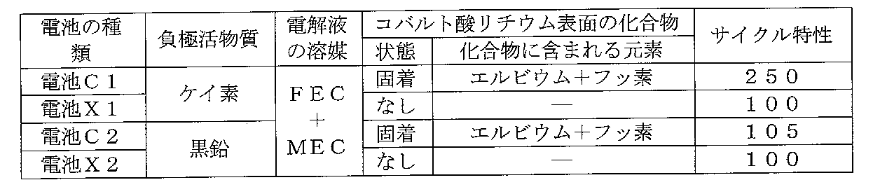
上記電池C1、C2、X1、X2のサイクル特性(200サイクル経過後の各電池の容量)を調べたので、その結果を表3に示す。尚、サイクル特性調査時の充放電条件は、1.0Itを750mAとした以外は、上記第1実施例の実験と同様の条件である。また、電池C1の値は、電池X1における200サイクル後の容量を100としたときの指数で表しており、電池C2の値は、電池X2における200サイクル後の容量を100としたときの指数で表している。
2 負極
3 セパレータ
4 正極集電タブ
5 負極集電タブ
6 アルミラミネート外装体
8 予備室
11 非水電解液二次電池
Claims (9)
- リチウム遷移金属複合酸化物の表面に、希土類元素とフッ素元素とを含む化合物が固着しており、且つ、当該化合物の平均粒子径が1nm以上100nm以下であることを特徴とする非水電解液二次電池用正極活物質。
- 上記フッ素元素と希土類元素とを含む化合物がフッ化エルビウムである、請求項1に記載の非水電解液二次電池用正極活物質。
- 上記リチウム遷移金属複合酸化物に対する上記フッ素元素と希土類元素とを含む化合物の割合が、希土類元素換算で、0.01質量%以上0.3質量%以下である、請求項1又は2に記載の非水電解液二次電池用正極活物質。
- pHを調整しつつ、フッ素を含む水溶性の化合物とリチウム遷移金属複合酸化物とを含む懸濁液に、希土類元素を含む化合物を溶解した水溶液を加えることを特徴とする非水電解液二次電池用正極活物質の製造方法。
- 上記リチウム遷移金属複合酸化物表面にフッ素元素と希土類元素とを含む化合物を固着させた後に500℃未満で熱処理する、請求項4に記載の非水電解液二次電池用正極活物質の製造方法。
- 上記請求項1~3の何れか1項に記載の非水電解液二次電池用正極活物質と、導電剤と、結着剤とを含むことを特徴とする非水電解液二次電池用正極。
- 上記請求項6に記載の正極と、負極と、非水電解液とを有することを特徴とする非水電解液二次電池。
- 上記負極に含まれる負極活物質には、炭素粒子、ケイ素粒子、及びケイ素合金粒子から成る群から選択される少なくとも1種が含有されている、請求項7に記載の非水電解液二次電池。
- 上記負極活物質には、ケイ素粒子又はケイ素合金粒子を含む化合物が用いられている、請求項8に記載の非水電解液二次電池。
Priority Applications (3)
| Application Number | Priority Date | Filing Date | Title |
|---|---|---|---|
| US13/982,389 US20130309576A1 (en) | 2011-01-28 | 2011-12-27 | Positive electrode active material for nonaqueous electrolyte secondary battery, method for producing the same, positive electrode for nonaqueous electrolyte secondary battery using the positive electrode active material, and nonaqueous electrolyte secondary battery using the positive electrode |
| CN2011800662891A CN103339769A (zh) | 2011-01-28 | 2011-12-27 | 非水电解液二次电池用正极活性物质、其制造方法、使用该正极活性物质的非水电解液二次电池用正极以及使用该正极的非水电解液二次电池 |
| JP2012554651A JP5931750B2 (ja) | 2011-01-28 | 2011-12-27 | 非水電解液二次電池用正極活物質、その製造方法、当該正極活物質を用いた非水電解液二次電池用正極、及び、当該正極を用いた非水電解液二次電池 |
Applications Claiming Priority (2)
| Application Number | Priority Date | Filing Date | Title |
|---|---|---|---|
| JP2011-016571 | 2011-01-28 | ||
| JP2011016571 | 2011-01-28 |
Publications (1)
| Publication Number | Publication Date |
|---|---|
| WO2012101949A1 true WO2012101949A1 (ja) | 2012-08-02 |
Family
ID=46580530
Family Applications (1)
| Application Number | Title | Priority Date | Filing Date |
|---|---|---|---|
| PCT/JP2011/080286 Ceased WO2012101949A1 (ja) | 2011-01-28 | 2011-12-27 | 非水電解液二次電池用正極活物質、その製造方法、当該正極活物質を用いた非水電解液二次電池用正極、及び、当該正極を用いた非水電解液二次電池 |
Country Status (4)
| Country | Link |
|---|---|
| US (1) | US20130309576A1 (ja) |
| JP (1) | JP5931750B2 (ja) |
| CN (1) | CN103339769A (ja) |
| WO (1) | WO2012101949A1 (ja) |
Cited By (3)
| Publication number | Priority date | Publication date | Assignee | Title |
|---|---|---|---|---|
| WO2015045315A1 (ja) * | 2013-09-30 | 2015-04-02 | 三洋電機株式会社 | 非水電解質二次電池用正極活物質及びそれを用いた非水電解質二次電池 |
| JP2015095352A (ja) * | 2013-11-12 | 2015-05-18 | 日亜化学工業株式会社 | 非水電解液二次電池用正極活物質の製造方法、非水電解液二次電池用正極及び非水電解液二次電池 |
| CN105190956A (zh) * | 2013-03-28 | 2015-12-23 | 三洋电机株式会社 | 非水电解质二次电池用正极、非水电解质二次电池用正极的制造方法以及非水电解质二次电池 |
Families Citing this family (8)
| Publication number | Priority date | Publication date | Assignee | Title |
|---|---|---|---|---|
| WO2012176902A1 (ja) * | 2011-06-24 | 2012-12-27 | 旭硝子株式会社 | リチウムイオン二次電池用正極活物質の製造方法、リチウムイオン二次電池用正極およびリチウムイオン二次電池 |
| US20170040606A1 (en) * | 2013-12-27 | 2017-02-09 | Sanyo Electric Co., Ltd. | Positive electrode active material for nonaqueous electrolyte secondary batteries and nonaqueous electrolyte secondary battery including the same |
| CN106104869B (zh) * | 2014-03-11 | 2019-01-22 | 三洋电机株式会社 | 非水电解质二次电池用正极活性物质以及非水电解质二次电池用正极 |
| KR101657142B1 (ko) * | 2014-08-21 | 2016-09-19 | 주식회사 포스코 | 리튬 이차 전지용 양극 활물질의 제조 방법 및 이에 따라 제조된 양극 활물질을 포함하는 리튬 이차 전지 |
| JP6632233B2 (ja) * | 2015-07-09 | 2020-01-22 | マクセルホールディングス株式会社 | 非水電解質二次電池 |
| DE202017007628U1 (de) * | 2016-07-05 | 2023-12-21 | Semiconductor Energy Laboratory Co., Ltd. | Positivelektrodenaktivmaterial und Sekundärbatterie |
| CN110603668A (zh) * | 2017-05-31 | 2019-12-20 | 松下知识产权经营株式会社 | 二次电池用正极和二次电池 |
| CN113675383A (zh) * | 2021-07-09 | 2021-11-19 | 惠州锂威新能源科技有限公司 | 一种改性正极材料及其制备方法、正极片以及锂离子电池 |
Citations (4)
| Publication number | Priority date | Publication date | Assignee | Title |
|---|---|---|---|---|
| JP2008536285A (ja) * | 2005-04-15 | 2008-09-04 | エナーセラミック インコーポレイテッド | フッ素化合物でコーティングされたリチウム二次電池用正極活物質及びその製造方法 |
| JP2008234988A (ja) * | 2007-03-20 | 2008-10-02 | Sony Corp | 負極およびその製造方法、ならびに電池およびその製造方法 |
| JP2010086922A (ja) * | 2008-10-02 | 2010-04-15 | Toda Kogyo Corp | リチウム複合化合物粒子粉末及びその製造方法、非水電解質二次電池 |
| JP2010165657A (ja) * | 2008-07-09 | 2010-07-29 | Sanyo Electric Co Ltd | 非水電解質二次電池用正極活物質、非水電解質二次電池用正極活物質の製造方法、非水電解質二次電池用正極及び非水電解質二次電池 |
Family Cites Families (5)
| Publication number | Priority date | Publication date | Assignee | Title |
|---|---|---|---|---|
| US20080081258A1 (en) * | 2006-09-28 | 2008-04-03 | Korea Electro Technology Research Institute | Carbon-coated composite material, manufacturing method thereof, positive electrode active material, and lithium secondary battery comprising the same |
| KR101009993B1 (ko) * | 2007-05-07 | 2011-01-21 | 주식회사 에너세라믹 | 리튬 이차 전지용 양극 활물질의 제조방법, 이 방법으로제조된 리튬 이차 전지용 양극 활물질 및 이를 포함하는리튬 이차 전지 |
| JP4656097B2 (ja) * | 2007-06-25 | 2011-03-23 | ソニー株式会社 | 非水電解質二次電池用正極活物質およびその製造方法、並びに非水電解質二次電池 |
| JP5310251B2 (ja) * | 2009-05-18 | 2013-10-09 | 信越化学工業株式会社 | 非水電解質二次電池用負極材の製造方法 |
| JP2012101948A (ja) * | 2010-11-05 | 2012-05-31 | Kansai Coke & Chem Co Ltd | 活性炭の製造方法 |
-
2011
- 2011-12-27 CN CN2011800662891A patent/CN103339769A/zh active Pending
- 2011-12-27 US US13/982,389 patent/US20130309576A1/en not_active Abandoned
- 2011-12-27 JP JP2012554651A patent/JP5931750B2/ja active Active
- 2011-12-27 WO PCT/JP2011/080286 patent/WO2012101949A1/ja not_active Ceased
Patent Citations (4)
| Publication number | Priority date | Publication date | Assignee | Title |
|---|---|---|---|---|
| JP2008536285A (ja) * | 2005-04-15 | 2008-09-04 | エナーセラミック インコーポレイテッド | フッ素化合物でコーティングされたリチウム二次電池用正極活物質及びその製造方法 |
| JP2008234988A (ja) * | 2007-03-20 | 2008-10-02 | Sony Corp | 負極およびその製造方法、ならびに電池およびその製造方法 |
| JP2010165657A (ja) * | 2008-07-09 | 2010-07-29 | Sanyo Electric Co Ltd | 非水電解質二次電池用正極活物質、非水電解質二次電池用正極活物質の製造方法、非水電解質二次電池用正極及び非水電解質二次電池 |
| JP2010086922A (ja) * | 2008-10-02 | 2010-04-15 | Toda Kogyo Corp | リチウム複合化合物粒子粉末及びその製造方法、非水電解質二次電池 |
Cited By (6)
| Publication number | Priority date | Publication date | Assignee | Title |
|---|---|---|---|---|
| CN105190956A (zh) * | 2013-03-28 | 2015-12-23 | 三洋电机株式会社 | 非水电解质二次电池用正极、非水电解质二次电池用正极的制造方法以及非水电解质二次电池 |
| WO2015045315A1 (ja) * | 2013-09-30 | 2015-04-02 | 三洋電機株式会社 | 非水電解質二次電池用正極活物質及びそれを用いた非水電解質二次電池 |
| CN105518911A (zh) * | 2013-09-30 | 2016-04-20 | 三洋电机株式会社 | 非水电解质二次电池用正极活性物质及使用其的非水电解质二次电池 |
| JPWO2015045315A1 (ja) * | 2013-09-30 | 2017-03-09 | 三洋電機株式会社 | 非水電解質二次電池用正極活物質及びそれを用いた非水電解質二次電池 |
| JP2015095352A (ja) * | 2013-11-12 | 2015-05-18 | 日亜化学工業株式会社 | 非水電解液二次電池用正極活物質の製造方法、非水電解液二次電池用正極及び非水電解液二次電池 |
| US10305095B2 (en) | 2013-11-12 | 2019-05-28 | Nichia Corporation | Method of producing positive electrode active material for non-aqueous electrolyte secondary battery, positive electrode for non-aqueous electrolyte secondary battery, and non-aqueous electrolyte secondary battery |
Also Published As
| Publication number | Publication date |
|---|---|
| JPWO2012101949A1 (ja) | 2014-06-30 |
| JP5931750B2 (ja) | 2016-06-08 |
| US20130309576A1 (en) | 2013-11-21 |
| CN103339769A (zh) | 2013-10-02 |
Similar Documents
| Publication | Publication Date | Title |
|---|---|---|
| JP5931750B2 (ja) | 非水電解液二次電池用正極活物質、その製造方法、当該正極活物質を用いた非水電解液二次電池用正極、及び、当該正極を用いた非水電解液二次電池 | |
| JP5931749B2 (ja) | 非水電解液二次電池用正極活物質、その製造方法、当該正極活物質を用いた非水電解液二次電池用正極、及び、当該正極を用いた非水電解液二次電池 | |
| JP5399188B2 (ja) | 非水電解質二次電池 | |
| JP6447620B2 (ja) | 非水電解質二次電池用正極活物質 | |
| KR20190131842A (ko) | 이차전지용 양극 활물질, 그 제조방법 및 이를 포함하는 리튬 이차전지 | |
| JP6236018B2 (ja) | 偏平形非水電解質二次電池及びそれを用いた組電池 | |
| JP5675113B2 (ja) | 非水電解質二次電池及び非水電解質二次電池用正極 | |
| CN103459321A (zh) | Li-Ni复合氧化物颗粒粉末及其制造方法、以及非水电解质二次电池 | |
| JP2009099523A (ja) | リチウム二次電池 | |
| JP6565916B2 (ja) | 非水電解質二次電池 | |
| CN105493334B (zh) | 扁平型非水电解质二次电池以及使用其的电池组 | |
| JP4989670B2 (ja) | 非水電解質二次電池用正極活物質、非水電解質二次電池用正極活物質の製造方法、非水電解質二次電池用正極及び非水電解質二次電池 | |
| JP6124303B2 (ja) | 非水電解液二次電池 | |
| WO2013002369A1 (ja) | 非水電解質二次電池及びその製造方法 | |
| US9478802B2 (en) | Nonaqueous electrolyte secondary battery | |
| JP6117553B2 (ja) | 非水電解質二次電池用正極、当該正極の製造方法、及び当該正極を用いた非水電解液二次電池 | |
| JP6299771B2 (ja) | 非水電解質二次電池用正極活物質及びそれを用いた非水電解質二次電池 | |
| JP2014029782A (ja) | 非水電解質二次電池用正極活物質、その正極活物質を用いた非水電解質二次電池用正極、及びその正極を用いた非水電解質二次電池 |
Legal Events
| Date | Code | Title | Description |
|---|---|---|---|
| 121 | Ep: the epo has been informed by wipo that ep was designated in this application |
Ref document number: 11856968 Country of ref document: EP Kind code of ref document: A1 |
|
| ENP | Entry into the national phase |
Ref document number: 2012554651 Country of ref document: JP Kind code of ref document: A |
|
| NENP | Non-entry into the national phase |
Ref country code: DE |
|
| WWE | Wipo information: entry into national phase |
Ref document number: 13982389 Country of ref document: US |
|
| 122 | Ep: pct application non-entry in european phase |
Ref document number: 11856968 Country of ref document: EP Kind code of ref document: A1 |