WO2012099242A1 - 給水装置 - Google Patents
給水装置 Download PDFInfo
- Publication number
- WO2012099242A1 WO2012099242A1 PCT/JP2012/051196 JP2012051196W WO2012099242A1 WO 2012099242 A1 WO2012099242 A1 WO 2012099242A1 JP 2012051196 W JP2012051196 W JP 2012051196W WO 2012099242 A1 WO2012099242 A1 WO 2012099242A1
- Authority
- WO
- WIPO (PCT)
- Prior art keywords
- pump
- curve
- control
- flow rate
- lift
- Prior art date
Links
Images


Classifications
-
- F—MECHANICAL ENGINEERING; LIGHTING; HEATING; WEAPONS; BLASTING
- F04—POSITIVE - DISPLACEMENT MACHINES FOR LIQUIDS; PUMPS FOR LIQUIDS OR ELASTIC FLUIDS
- F04D—NON-POSITIVE-DISPLACEMENT PUMPS
- F04D15/00—Control, e.g. regulation, of pumps, pumping installations or systems
-
- F—MECHANICAL ENGINEERING; LIGHTING; HEATING; WEAPONS; BLASTING
- F04—POSITIVE - DISPLACEMENT MACHINES FOR LIQUIDS; PUMPS FOR LIQUIDS OR ELASTIC FLUIDS
- F04D—NON-POSITIVE-DISPLACEMENT PUMPS
- F04D15/00—Control, e.g. regulation, of pumps, pumping installations or systems
- F04D15/0066—Control, e.g. regulation, of pumps, pumping installations or systems by changing the speed, e.g. of the driving engine
-
- F—MECHANICAL ENGINEERING; LIGHTING; HEATING; WEAPONS; BLASTING
- F04—POSITIVE - DISPLACEMENT MACHINES FOR LIQUIDS; PUMPS FOR LIQUIDS OR ELASTIC FLUIDS
- F04D—NON-POSITIVE-DISPLACEMENT PUMPS
- F04D15/00—Control, e.g. regulation, of pumps, pumping installations or systems
- F04D15/0088—Testing machines
-
- F—MECHANICAL ENGINEERING; LIGHTING; HEATING; WEAPONS; BLASTING
- F05—INDEXING SCHEMES RELATING TO ENGINES OR PUMPS IN VARIOUS SUBCLASSES OF CLASSES F01-F04
- F05D—INDEXING SCHEME FOR ASPECTS RELATING TO NON-POSITIVE-DISPLACEMENT MACHINES OR ENGINES, GAS-TURBINES OR JET-PROPULSION PLANTS
- F05D2270/00—Control
- F05D2270/30—Control parameters, e.g. input parameters
- F05D2270/301—Pressure
- F05D2270/3013—Outlet pressure
Definitions
- the present invention relates to a water supply device that supplies water such as tap water to an apartment house or a building using a pump.
- FIG. 1 shows a typical example of such a water supply apparatus.
- the water supply apparatus includes two pumps 1 each having a motor M for supplying water under pressure, and motors for driving the pumps 1.
- An inverter (frequency converter) 2 that supplies power to M is provided.
- the water supply device includes a pressure tank 3 and a discharge-side pressure sensor 4 on the discharge side of the pump 1, and a flow switch (flow rate detection means) 6 and a check valve 7 for each pump 1.
- a suction side pipe 8 of the pump 1 is connected to a water main pipe 9, and a suction side pressure sensor 10 and a backflow prevention device 11 are provided in the suction side pipe 8.
- a bypass pipe 12 for supplying water only with the pressure of the water main pipe 9 is provided between the suction side pipe 8 and the discharge side pipe 13 of the pump 1.
- a check valve 14 is provided in the middle of the bypass pipe 12.
- the control unit 15 that controls the pump 1 performs rotation speed control and number control of the pump 1 according to the situation based on signals from these sensors.
- the suction side pipe of the pump is not a direct connection type water supply device connected to the water main, but a water receiving tank type water supply device
- the pump suction side piping is connected to the water receiving tank and provided in the water receiving tank.
- a water level detector is connected to the controller.
- a backflow prevention device, a suction side pressure sensor, and a bypass pipe are not provided.
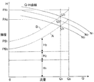
- FIG. 2 shows a required lift curve A indicating the relationship between the flow rate used and the lift (head) required for the flow rate in the water supply device, and a standard control lift curve B set based on the required lift curve A.
- the pump QH curve pump speeds N 1 , N 2 and N 3 .
- the horizontal axis indicates the flow rate Q
- the vertical axis indicates the head (head) H.
- the required head curve A is, for example, the sum of the head of the building (height of the top floor) H 1 , the pressure required for water equipment (pressure loss of the water equipment) H 2 , and the pipe loss H 3 depending on the flow rate (H 1 + H 2 + H 3 ).
- H 1 + H 2 + H 3 the pressure required for water equipment
- H 3 the pipe loss H 3 depending on the flow rate
- This required head curve A is merely the relationship between the ideal head and the flow rate used, and in actual design, for example, standard control with a margin of about a dozen percent with respect to the required head curve A. It has been widely practiced to set a lift head curve B and control the rotational speed of the pump based on the standard control lift curve B.
- This standard control lift curve B shows a lift (minimum required pressure) PB 1 that gives a margin of about 10% to the lift PB 0 when the use flow rate is 0, and when the use flow rate is the final point Q 0 . It is shown as a curve that smoothly connects the head (maximum required pressure) PA 1 with a margin of about 10% to the head PA 0 .
- This standard control head curve B is stored in the storage unit of the control unit 15 of the water supply apparatus shown in FIG. 1, and based on this standard control head curve B, that is, for example, as shown in FIG.
- the operating flow rate is Q 1
- the rotational speed of the pump 1 is controlled so that the intersection point U 3 between the flow rate Q 1 and the standard control head curve B becomes the operating point (rotational speed N 1 ) of the pump 1. .
- a standard control lift curve B having a margin of about 10% or more is set for the required lift curve A, and the rotational speed of the pump is controlled based on the standard control lift curve B. For example, when corrosion occurs in the pipe and the pipe loss becomes larger than the original design, the water supply device is prevented from failing to use its performance, or for some reason on the user side, If there is a request for more flow, this request can be met.
- the rotational speed of the pump may be controlled to N 2 so that the intersection point U 2 , which has a lower head than that, becomes the operating point.
- the rotational speed of the pump is increased, to consume much more power Become. This is contrary to the recent needs for energy conservation.
- the user may not need to control the rotation speed of the pump based on the standard control head curve with sufficient margin. In such a case, it is possible to contribute to energy saving by controlling the rotational speed of the pump based on the control head curve having a minimum necessary margin.
- Patent Document 1 is not intended to save such energy.
- the present invention has been made in view of the above circumstances, and it is possible to control the pump so that the rotational speed of the pump becomes low while ensuring a constant flow rate, so that the water supply device can meet the demand for energy saving.
- the purpose is to provide.
- the invention according to claim 1 is a pump that pressurizes and feeds water, a frequency converter that supplies electric power to the pump and operates the pump at an arbitrary rotational speed, and a pressure on a discharge side of the pump.
- a discharge-side pressure sensor to detect, and a control unit for controlling the rotation speed of the pump, wherein the control unit stores a plurality of control head curves indicating different relationships between the flow rate and the head, and alternatively
- the water supply device is characterized in that the rotational speed of the pump is controlled based on the selected control head curve.
- the first control lift curve and the second control lift curve in which the pressure (lift) is set lower than the first control lift curve are stored in the control unit. Then, usually, the rotational speed of the pump is controlled based on the first control lift curve, and if necessary, the pump rotational speed is controlled based on the second control lift curve. Compared to the case where the rotational speed of the pump is controlled based only on the curve, it is possible to save energy by reducing the rotational speed of the pump while maintaining the amount of water used.
- the invention according to claim 2 is a switch button for sequentially switching a plurality of control head curves stored in the control unit, and a degree of energy saving corresponding to the control head curve used for controlling the rotational speed of the pump.
- the user can easily select the control head curve used for the control by using the switching button, and the selected state can be confirmed on the energy saving display section.
- the plurality of control lift curves are a standard control lift curve and a small flow rate energy saving control lift in which the lift on the small flow rate side is set lower than the standard control lift curve. It is a water supply apparatus of Claim 1 or 2 characterized by including a curve.
- the plurality of control lift curves are a standard control lift curve, and a medium flow rate energy-saving control lift in which the lift of the medium flow rate range is set lower than the standard control lift curve. It is a water supply apparatus in any one of the Claims 1 thru
- the plurality of control lift curves are a standard control lift curve and a large flow rate energy-saving control lift in which the lift of the large flow rate range is set lower than the standard control lift curve. It is a water supply apparatus in any one of the Claims 1 thru
- the plurality of control lift curves include a standard control lift curve and a total flow rate energy saving type in which the lift of the entire flow rate range is set to be substantially parallel to the standard control lift curve. It is a water supply apparatus in any one of the Claims 1 thru
- the water supply device of the present invention even if the amount of water used is the same, it is possible to operate the pump by selecting an operation point with a low rotation speed as necessary, thereby reducing the power used during water supply. It can save energy and lead to CO 2 reduction.
- FIG. 3 is a diagram illustrating a configuration example of the water supply device according to the embodiment of the present invention.
- the control unit 15 of the water supply apparatus includes a setting unit 16, a storage unit 17, a calculation unit 18, a display unit 19, and an I / O unit 20.
- the setting unit 16 and the display unit 19 are provided in the operation panel 21 of the water supply device.
- the configuration other than the control unit 15 is substantially the same as the configuration of the conventional water supply apparatus shown in FIG.
- the setting unit 16 is used to set various setting values such as a plurality of control head curves indicating different relationships between the flow rate and the head by an external operation.
- Various set values such as a plurality of control head curves set in the setting unit 16 are stored in the storage unit 17.
- the lift (minimum required pressure) PB 1 when the use flow rate is 0 the lift (maximum required pressure) PA 1 when the use flow rate is the final point Q 0 , and the like are input to the storage unit 17 as set values.
- the I / O unit 20 receives signals from various sensors installed in the water supply device, such as the output of the discharge side pressure sensor 4 and the signal of the flow switch 6, and sends them to the calculation unit 18.
- the I / O unit 20 and each inverter 2 are connected to each other by communication means such as RS485, and various setting values, frequency command values, start / stop signals (start / stop signals), etc. from the control unit 15 to the inverter 2.
- the control signal is sent to the control unit 15 from the inverter 2 and the operation status such as the actual frequency value and current value is sequentially sent.
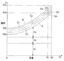
- FIG. 4 shows a plurality of control head curves set via the setting unit 16 and stored in the storage unit 17.
- the standard control lift curve B having a margin of, for example, about a dozen percent with respect to the required lift curve A obtained from 3
- three total flow rate energy-saving control lift curves C 1 , C 2 a total of four control head curve of C 3 is used.
- the lift curves C 1 , C 2 , and C 3 for the energy saving type control for the entire flow rate range are set substantially lower in parallel with the lift curve B for the standard control over the entire flow rate range, and from the necessary lift curve A
- the head is also set high.
- lift is set to turn lower.
- One of the four control lift curves B, C 1 , C 2 , C 3 is selected, and the pump 1 is based on the selected control lift curve B, C 1 , C 2 or C 3.
- the rotation speed is controlled.
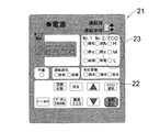
- FIG. 5 shows a plan view of the operation panel 21 provided in the water supply apparatus.
- the operation panel 21 includes a switching button 22 for sequentially switching the four control head curves B, C 1 , C 2 , C 3 stored in the control unit 17, and the rotational speed of the pump 1.
- an energy saving display unit 23 indicating the degree of energy saving corresponding to the control head curve used for the control.
- the standard control lift curve B is used for controlling the rotational speed of the pump 1 without the lamp of the energy saving display section 23 being lit.
- the switch button 22 is pressed once, the lamp corresponding to “L” in the energy saving display section 23 is turned on, and the energy flow control curve C 1 for the entire flow rate region is used for controlling the rotational speed of the pump 1.
- the switching button 22 is pressed twice, the lamp corresponding to “M” in the energy saving display section 23 is turned on, and the entire flow rate energy saving type control head curve C 2 is used for controlling the rotational speed of the pump 1.
- the switch button 22 pressing the switch button 22 three times, the lamp is lit corresponding to the "H" of the energy-saving display unit 23, the total flow rate range energy-saving control head curve C 3 is used to control the rotational speed of the pump 1 The
- the switching button 22 is pressed four times, the original state is restored.
- the user can easily switch the control head curve B, C 1 , C 2 or C 3 used for the control by pressing the switch button 22, and confirm this switching state on the energy saving display unit 23. Can do.
- the pump can be operated by selecting an operation point with a low rotation speed as necessary, thereby reducing the power consumed during water supply and saving energy. 2 can be reduced.
- the head is set low over the entire flow rate range in parallel with the standard control head curve B, and the head is set higher than the required head curve A.
- An example is shown in which a plurality of (in this example, three) lift curves C for energy saving control in the entire flow rate region are used to achieve substantially constant energy saving in the entire flow rate region.
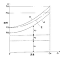
- an intermediate flow rate energy-saving control lift curve D in which the lift in the medium flow rate range is set lower than the standard control lift curve B is used so as to save energy mainly in the medium flow rate range.
- stepwise energy saving may be achieved by using a plurality of medium flow rate energy saving type control lift curves D having a difference in lift between the standard control lift curve B and the medium flow rate range.
- a large flow rate energy-saving control lift curve E in which the lift in the large flow rate region is set lower than the standard control lift curve B is used to save energy mainly in the large flow rate region. You may do it.
- stepwise energy saving may be achieved by using a plurality of large-flow-rate energy-saving control lift curves E in which the difference in lift between the standard control lift curve B and the large-flow region is different.
- the energy saving control head curve F is used mainly in the small flow rate region, by using the small flow rate energy saving type control head curve F in which the head in the small flow region is set lower than the standard control head curve B. You may do it.
- stepwise energy saving may be achieved by using a plurality of small-flow-rate energy-saving control lift curves F in which the difference between the standard control lift curve B and the lift in the small-flow region is different.
- the rotational speed of the pump may be controlled so as to obtain a desired flow rate and head while considering the energy saving effect by arbitrarily combining the small flow rate range energy-saving control head curve F shown in FIG.
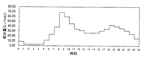
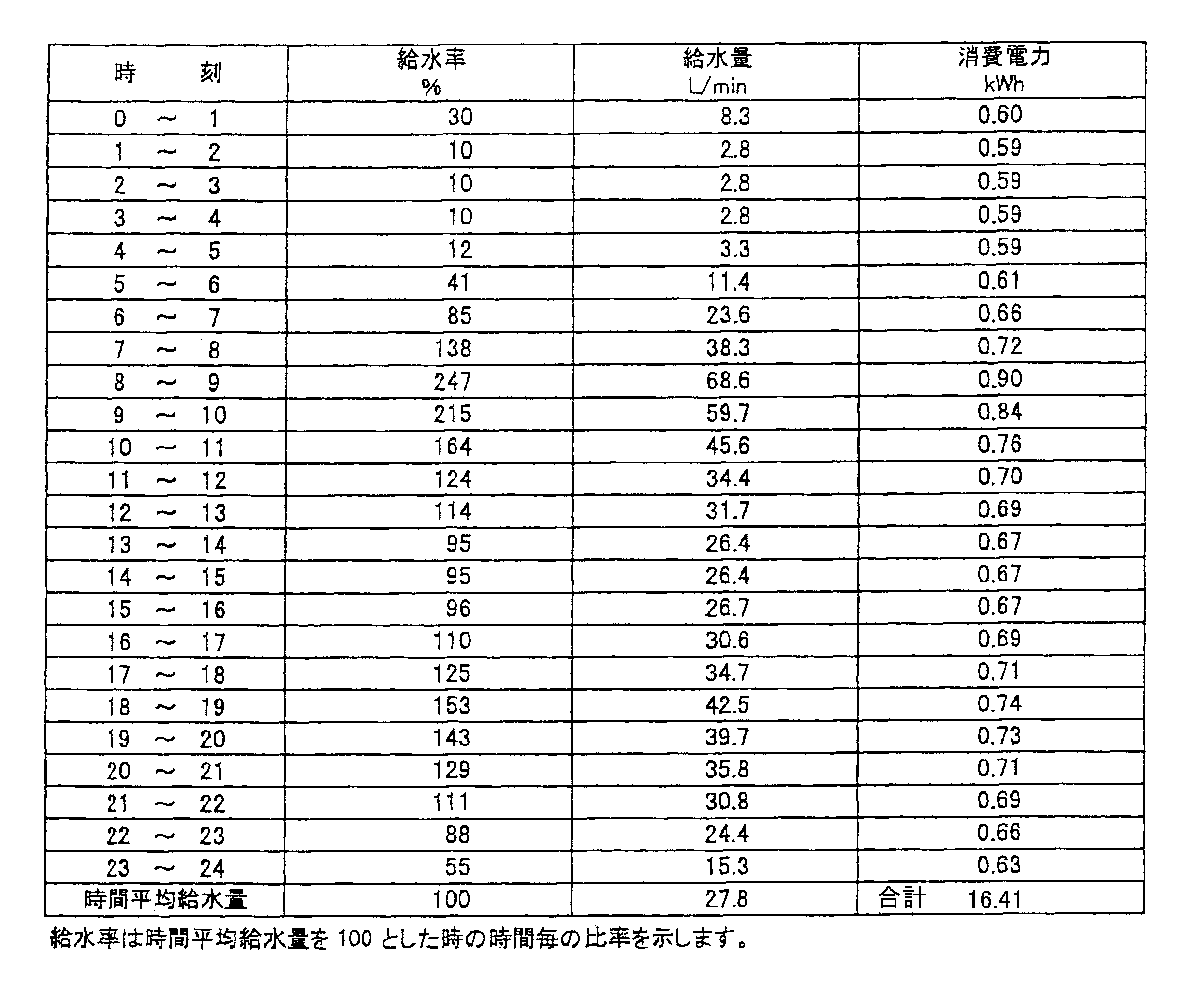
- Table 1 shows the relationship between time, water supply rate, water supply amount and power consumption (hourly power consumption), and table 1 shows the relationship between time, water supply rate, water supply amount and power consumption (power consumption per hour) when the head is 40 m 2 respectively.
- control lift curves may be used to select a control lift curve that raises the lift when the user feels that the lift is low.
- the control head curve is obtained by storing the standard control head curve B and several control head curves in which the heads of all or a part of the flow range of the curve B are lowered in the control unit.
- the control lift curve B and several control lift curves in which the lift in all or a part of the flow rate range of the curve B is increased are stored in the control unit, and the control lift curve is selected. You may make it select.
- the water supply apparatus of the present invention selects the control head curve for the purpose of energy saving to reduce the power consumption of the operation of the pump, but the present invention is not necessarily limited to this purpose. It is applicable also to the water supply apparatus which selects the control head curve for the purpose.
- the present invention can be applied to a water supply device that supplies water such as tap water to an apartment house or a building using a pump.
Landscapes
- Engineering & Computer Science (AREA)
- Mechanical Engineering (AREA)
- General Engineering & Computer Science (AREA)
- Control Of Non-Positive-Displacement Pumps (AREA)
- Control Of Positive-Displacement Pumps (AREA)
Abstract
Description

2 インバータ(周波数変換器)
3 圧力タンク
4 吐出側圧力センサ
8 吸込側配管
9 水道本管
10 吸込側圧力センサ
12 バイパス管
13 吐出側配管
15 制御部
16 設定部
17 記憶部
18 演算部
19 表示部
20 I/O部
21 運転パネル
22 切換ボタン
23 省エネ表示部
A 必要揚程曲線
B 標準制御用揚程曲線
C 全流量域省エネ型制御用揚程曲線
D 中流量域省エネ型制御用揚程曲線
E 大流量域省エネ型制御用揚程曲線
F 小流量域省エネ型制御用揚程曲線
Claims (6)
- 水を加圧して送水するポンプと、
前記ポンプに電力を供給して該ポンプを任意の回転速度で運転する周波数変換器と、
前記ポンプの吐出側の圧力を検知する吐出側圧力センサと、
前記ポンプの回転速度を制御する制御部とを備え、
前記制御部には、流量と揚程の異なる関係を示す複数の制御用揚程曲線が記憶され、択一的に選択された制御用揚程曲線に基づいて前記ポンプの回転速度が制御されることを特徴とする給水装置。 - 前記制御部に記憶されている複数の制御用揚程曲線を順次切換える切換ボタンと、ポンプの回転速度の制御に使用される制御用揚程曲線に対応した省エネルギーの程度を示す省エネ表示部とを有する運転パネルを有することを特徴とする請求項1記載の給水装置。
- 前記複数の制御用揚程曲線は、標準制御用揚程曲線と、標準制御用揚程曲線に対して小流量側の揚程を低く設定した小流量域省エネ型制御用揚程曲線とを含むことを特徴とする請求項1または2に記載の給水装置。
- 前記複数の制御用揚程曲線は、標準制御用揚程曲線と、標準制御用揚程曲線に対して中流量域の揚程を低く設定した中流量域省エネ型制御用揚程曲線とを含むことを特徴とする請求項1乃至3のいずれかに記載の給水装置。
- 前記複数の制御用揚程曲線は、標準制御用揚程曲線と、標準制御用揚程曲線に対して大流量域の揚程を低く設定した大流量域省エネ型制御用揚程曲線とを含むことを特徴とする請求項1乃至4のいずれかに記載の給水装置。
- 前記複数の制御用揚程曲線は、標準制御用揚程曲線と、標準制御用揚程曲線に対して略並行に全流量域の揚程を低く設定した全流量域省エネ型制御用揚程曲線とを含むことを特徴とする請求項1乃至5のいずれかに記載の給水装置。
Priority Applications (5)
| Application Number | Priority Date | Filing Date | Title |
|---|---|---|---|
| US13/980,259 US20140044560A1 (en) | 2011-01-21 | 2012-01-20 | Water supply apparatus |
| JP2012553784A JP5914365B2 (ja) | 2011-01-21 | 2012-01-20 | 給水装置 |
| CN201280005545.0A CN103314217B (zh) | 2011-01-21 | 2012-01-20 | 供水装置 |
| KR1020137021450A KR101760547B1 (ko) | 2011-01-21 | 2012-01-20 | 급수 장치 |
| EP12736816.5A EP2667033B1 (en) | 2011-01-21 | 2012-01-20 | Water supply apparatus |
Applications Claiming Priority (2)
| Application Number | Priority Date | Filing Date | Title |
|---|---|---|---|
| JP2011-010432 | 2011-01-21 | ||
| JP2011010432 | 2011-01-21 |
Publications (1)
| Publication Number | Publication Date |
|---|---|
| WO2012099242A1 true WO2012099242A1 (ja) | 2012-07-26 |
Family
ID=46515859
Family Applications (1)
| Application Number | Title | Priority Date | Filing Date |
|---|---|---|---|
| PCT/JP2012/051196 WO2012099242A1 (ja) | 2011-01-21 | 2012-01-20 | 給水装置 |
Country Status (6)
| Country | Link |
|---|---|
| US (1) | US20140044560A1 (ja) |
| EP (1) | EP2667033B1 (ja) |
| JP (1) | JP5914365B2 (ja) |
| KR (1) | KR101760547B1 (ja) |
| CN (1) | CN103314217B (ja) |
| WO (1) | WO2012099242A1 (ja) |
Cited By (8)
| Publication number | Priority date | Publication date | Assignee | Title |
|---|---|---|---|---|
| CN103742425A (zh) * | 2014-01-22 | 2014-04-23 | 江苏双轮泵业机械制造有限公司 | 水循环系统节能修正方法 |
| JP2014138497A (ja) * | 2013-01-17 | 2014-07-28 | Ebara Corp | 流体供給装置 |
| WO2014175248A1 (ja) | 2013-04-26 | 2014-10-30 | 株式会社 荏原製作所 | ポンプ装置 |
| JP2014214715A (ja) * | 2013-04-26 | 2014-11-17 | 株式会社荏原製作所 | ポンプ装置 |
| JP2014214743A (ja) * | 2013-04-30 | 2014-11-17 | 株式会社荏原製作所 | ポンプ装置 |
| JP2019210819A (ja) * | 2018-05-31 | 2019-12-12 | 株式会社荏原製作所 | 給水装置を制御するための制御ユニット、及び給水装置 |
| JP2019210820A (ja) * | 2018-05-31 | 2019-12-12 | 株式会社荏原製作所 | 給水装置を制御するための制御ユニット、及び給水装置 |
| KR20220161695A (ko) * | 2021-05-31 | 2022-12-07 | (주) 인정테크 | 인버터 부스터 펌프 시스템의 가변압 제어방법 |
Families Citing this family (6)
| Publication number | Priority date | Publication date | Assignee | Title |
|---|---|---|---|---|
| EP2910788B1 (en) * | 2014-02-25 | 2018-04-04 | TACO ITALIA S.r.l. | Method for controlling a pumping station within a fluid circulation system, related circulation system and pumping station for realizing said method |
| EP3156656B1 (de) * | 2015-10-16 | 2020-03-25 | Grundfos Holding A/S | Pumpensteuerverfahren und druckerhöhungsvorrichtung |
| CN108825520A (zh) * | 2018-05-04 | 2018-11-16 | 四川省宜宾惠美线业有限责任公司 | 一种离心式水泵节能的应用方法 |
| CN109059216B (zh) * | 2018-06-20 | 2020-08-04 | 广东美的暖通设备有限公司 | 空调系统及其水泵的控制方法和装置 |
| EP3599037A1 (de) * | 2018-07-25 | 2020-01-29 | Primetals Technologies Germany GmbH | Kühlstrecke mit einstellung der kühlmittelströme durch pumpen |
| DE102018217439A1 (de) * | 2018-10-11 | 2020-04-16 | Albert Ziegler Gmbh | Pumpeneinrichtung |
Citations (3)
| Publication number | Priority date | Publication date | Assignee | Title |
|---|---|---|---|---|
| JPS5951193A (ja) | 1982-09-20 | 1984-03-24 | Hitachi Ltd | 可変速ポンプを備えた給水装置 |
| JP2000110769A (ja) * | 1998-10-02 | 2000-04-18 | Toshiba Corp | 可変速ポンプの速度制御装置 |
| JP2005351252A (ja) * | 2004-06-14 | 2005-12-22 | Nikkiso Co Ltd | 複数のタンクからの液体払い出し方法および液体払い出し装置 |
Family Cites Families (13)
| Publication number | Priority date | Publication date | Assignee | Title |
|---|---|---|---|---|
| US4370098A (en) * | 1980-10-20 | 1983-01-25 | Esco Manufacturing Company | Method and apparatus for monitoring and controlling on line dynamic operating conditions |
| US5240380A (en) * | 1991-05-21 | 1993-08-31 | Sundstrand Corporation | Variable speed control for centrifugal pumps |
| JP3922760B2 (ja) * | 1997-04-25 | 2007-05-30 | 株式会社荏原製作所 | 流体機械 |
| US6468042B2 (en) * | 1999-07-12 | 2002-10-22 | Danfoss Drives A/S | Method for regulating a delivery variable of a pump |
| JP3768045B2 (ja) * | 1999-09-24 | 2006-04-19 | 株式会社日立産機システム | インバータ |
| EP1286458A1 (de) * | 2001-08-22 | 2003-02-26 | Pumpenfabrik Ernst Vogel Gesellschaft m.b.H. | Verfahren und Vorrichtung zur Regelung von Kreiselarbeitsmaschinen |
| JP3917835B2 (ja) * | 2001-09-28 | 2007-05-23 | 横河電機株式会社 | 加圧送水ポンプシステム |
| EP1329672B1 (en) * | 2002-01-17 | 2006-10-11 | Hitachi, Ltd. | Energy collecting system and method of operating the same |
| JP4393310B2 (ja) * | 2004-08-25 | 2010-01-06 | 株式会社日立製作所 | ポンプ制御装置、ポンプ制御方法及びポンプ制御プログラム |
| CN1774994A (zh) * | 2005-12-15 | 2006-05-24 | 西北农林科技大学 | 基于变频恒压控制下的喷微灌单元设计方法 |
| CN101556068A (zh) * | 2008-04-11 | 2009-10-14 | 上海瀚艺冷冻机械有限公司 | 中央空调系统中循环泵的恒压变频节能控制方法 |
| JP2010209698A (ja) * | 2009-03-06 | 2010-09-24 | Toshiba Mitsubishi-Electric Industrial System Corp | 冷却設備ポンプ省エネ制御装置 |
| JP2011185190A (ja) * | 2010-03-10 | 2011-09-22 | Ebara Corp | 制御装置一体型モータポンプ |
-
2012
- 2012-01-20 US US13/980,259 patent/US20140044560A1/en not_active Abandoned
- 2012-01-20 EP EP12736816.5A patent/EP2667033B1/en active Active
- 2012-01-20 KR KR1020137021450A patent/KR101760547B1/ko active IP Right Grant
- 2012-01-20 WO PCT/JP2012/051196 patent/WO2012099242A1/ja active Application Filing
- 2012-01-20 JP JP2012553784A patent/JP5914365B2/ja active Active
- 2012-01-20 CN CN201280005545.0A patent/CN103314217B/zh active Active
Patent Citations (3)
| Publication number | Priority date | Publication date | Assignee | Title |
|---|---|---|---|---|
| JPS5951193A (ja) | 1982-09-20 | 1984-03-24 | Hitachi Ltd | 可変速ポンプを備えた給水装置 |
| JP2000110769A (ja) * | 1998-10-02 | 2000-04-18 | Toshiba Corp | 可変速ポンプの速度制御装置 |
| JP2005351252A (ja) * | 2004-06-14 | 2005-12-22 | Nikkiso Co Ltd | 複数のタンクからの液体払い出し方法および液体払い出し装置 |
Cited By (12)
| Publication number | Priority date | Publication date | Assignee | Title |
|---|---|---|---|---|
| JP2014138497A (ja) * | 2013-01-17 | 2014-07-28 | Ebara Corp | 流体供給装置 |
| WO2014175248A1 (ja) | 2013-04-26 | 2014-10-30 | 株式会社 荏原製作所 | ポンプ装置 |
| JP2014214715A (ja) * | 2013-04-26 | 2014-11-17 | 株式会社荏原製作所 | ポンプ装置 |
| KR20160002957A (ko) | 2013-04-26 | 2016-01-08 | 가부시키가이샤 에바라 세이사꾸쇼 | 펌프 장치 |
| JP2014214743A (ja) * | 2013-04-30 | 2014-11-17 | 株式会社荏原製作所 | ポンプ装置 |
| CN103742425A (zh) * | 2014-01-22 | 2014-04-23 | 江苏双轮泵业机械制造有限公司 | 水循环系统节能修正方法 |
| JP2019210819A (ja) * | 2018-05-31 | 2019-12-12 | 株式会社荏原製作所 | 給水装置を制御するための制御ユニット、及び給水装置 |
| JP2019210820A (ja) * | 2018-05-31 | 2019-12-12 | 株式会社荏原製作所 | 給水装置を制御するための制御ユニット、及び給水装置 |
| JP7081984B2 (ja) | 2018-05-31 | 2022-06-07 | 株式会社荏原製作所 | 給水装置を制御するための制御ユニット、及び給水装置 |
| JP7081985B2 (ja) | 2018-05-31 | 2022-06-07 | 株式会社荏原製作所 | 給水装置を制御するための制御ユニット、及び給水装置 |
| KR20220161695A (ko) * | 2021-05-31 | 2022-12-07 | (주) 인정테크 | 인버터 부스터 펌프 시스템의 가변압 제어방법 |
| KR102502146B1 (ko) | 2021-05-31 | 2023-02-23 | (주) 인정테크 | 인버터 부스터 펌프 시스템의 가변압 제어방법 |
Also Published As
| Publication number | Publication date |
|---|---|
| EP2667033A4 (en) | 2018-01-24 |
| KR20140007838A (ko) | 2014-01-20 |
| KR101760547B1 (ko) | 2017-07-21 |
| JPWO2012099242A1 (ja) | 2014-06-30 |
| US20140044560A1 (en) | 2014-02-13 |
| EP2667033B1 (en) | 2019-10-23 |
| JP5914365B2 (ja) | 2016-05-11 |
| EP2667033A1 (en) | 2013-11-27 |
| CN103314217A (zh) | 2013-09-18 |
| CN103314217B (zh) | 2015-12-23 |
Similar Documents
| Publication | Publication Date | Title |
|---|---|---|
| JP5914365B2 (ja) | 給水装置 | |
| JP6100172B2 (ja) | 給水装置及び給水方法 | |
| CN201347566Y (zh) | 变频恒压供水自动控制系统 | |
| JP4691519B2 (ja) | 中高層建物用増圧給水システム | |
| JP4804787B2 (ja) | 給水装置 | |
| JP5643385B2 (ja) | 増圧給水システム | |
| KR101170425B1 (ko) | 에너지 절감을 위한 부스터펌프 병렬운전 방법 | |
| JP6121267B2 (ja) | 増圧給水システム | |
| CN203866905U (zh) | 一种超高层建筑无负压供水设备 | |
| RU2399396C1 (ru) | Способ управления системой хозяйственно-питьевого и пожарного водоснабжения и устройство для осуществления способа | |
| JPH07331711A (ja) | 中高層建物用増圧給水システム | |
| CN111206651A (zh) | 一种智能控制调压供水方法 | |
| CN108222126A (zh) | 一种高层楼宇自分区叠压供水系统及供水方法 | |
| JP5362438B2 (ja) | 増圧給水システム | |
| CN210238630U (zh) | 一种叠压式双重供水设备 | |
| CN207405692U (zh) | 一种节能最大化的压力供水变频控制装置 | |
| JP5022389B2 (ja) | 増圧給水システム | |
| CN205530466U (zh) | 一种供水稳定的高层叠压供水节能系统 | |
| RU86882U1 (ru) | Насосная установка хозяйственно-питьевого и противопожарного водоснабжения | |
| CN212534298U (zh) | 一种多功能无负压节能供水装置 | |
| JP2015010405A (ja) | 増圧給水システム | |
| CN102720246A (zh) | 组合式加压泵站 | |
| CN207314442U (zh) | 一种高层建筑楼宇高低区节能供水设备 | |
| JPH0819915B2 (ja) | 可変速ポンプの運転装置 | |
| CN205062914U (zh) | 一种变频式无负压供水设备 |
Legal Events
| Date | Code | Title | Description |
|---|---|---|---|
| 121 | Ep: the epo has been informed by wipo that ep was designated in this application |
Ref document number: 12736816 Country of ref document: EP Kind code of ref document: A1 |
|
| ENP | Entry into the national phase |
Ref document number: 2012553784 Country of ref document: JP Kind code of ref document: A |
|
| WWE | Wipo information: entry into national phase |
Ref document number: 2012736816 Country of ref document: EP |
|
| NENP | Non-entry into the national phase |
Ref country code: DE |
|
| ENP | Entry into the national phase |
Ref document number: 20137021450 Country of ref document: KR Kind code of ref document: A |
|
| WWE | Wipo information: entry into national phase |
Ref document number: 13980259 Country of ref document: US |