WO2012099188A1 - R-t-b系焼結磁石 - Google Patents
R-t-b系焼結磁石 Download PDFInfo
- Publication number
- WO2012099188A1 WO2012099188A1 PCT/JP2012/051038 JP2012051038W WO2012099188A1 WO 2012099188 A1 WO2012099188 A1 WO 2012099188A1 JP 2012051038 W JP2012051038 W JP 2012051038W WO 2012099188 A1 WO2012099188 A1 WO 2012099188A1
- Authority
- WO
- WIPO (PCT)
- Prior art keywords
- sintered magnet
- rare earth
- rtb
- amount
- surface layer
- Prior art date
Links
Images


Classifications
-
- H—ELECTRICITY
- H01—ELECTRIC ELEMENTS
- H01F—MAGNETS; INDUCTANCES; TRANSFORMERS; SELECTION OF MATERIALS FOR THEIR MAGNETIC PROPERTIES
- H01F1/00—Magnets or magnetic bodies characterised by the magnetic materials therefor; Selection of materials for their magnetic properties
- H01F1/01—Magnets or magnetic bodies characterised by the magnetic materials therefor; Selection of materials for their magnetic properties of inorganic materials
- H01F1/03—Magnets or magnetic bodies characterised by the magnetic materials therefor; Selection of materials for their magnetic properties of inorganic materials characterised by their coercivity
- H01F1/032—Magnets or magnetic bodies characterised by the magnetic materials therefor; Selection of materials for their magnetic properties of inorganic materials characterised by their coercivity of hard-magnetic materials
- H01F1/04—Magnets or magnetic bodies characterised by the magnetic materials therefor; Selection of materials for their magnetic properties of inorganic materials characterised by their coercivity of hard-magnetic materials metals or alloys
- H01F1/047—Alloys characterised by their composition
- H01F1/053—Alloys characterised by their composition containing rare earth metals
- H01F1/0536—Alloys characterised by their composition containing rare earth metals sintered
-
- B—PERFORMING OPERATIONS; TRANSPORTING
- B22—CASTING; POWDER METALLURGY
- B22F—WORKING METALLIC POWDER; MANUFACTURE OF ARTICLES FROM METALLIC POWDER; MAKING METALLIC POWDER; APPARATUS OR DEVICES SPECIALLY ADAPTED FOR METALLIC POWDER
- B22F3/00—Manufacture of workpieces or articles from metallic powder characterised by the manner of compacting or sintering; Apparatus specially adapted therefor ; Presses and furnaces
- B22F3/24—After-treatment of workpieces or articles
-
- C—CHEMISTRY; METALLURGY
- C22—METALLURGY; FERROUS OR NON-FERROUS ALLOYS; TREATMENT OF ALLOYS OR NON-FERROUS METALS
- C22C—ALLOYS
- C22C33/00—Making ferrous alloys
- C22C33/02—Making ferrous alloys by powder metallurgy
- C22C33/0257—Making ferrous alloys by powder metallurgy characterised by the range of the alloying elements
- C22C33/0278—Making ferrous alloys by powder metallurgy characterised by the range of the alloying elements with at least one alloying element having a minimum content above 5%
-
- C—CHEMISTRY; METALLURGY
- C22—METALLURGY; FERROUS OR NON-FERROUS ALLOYS; TREATMENT OF ALLOYS OR NON-FERROUS METALS
- C22C—ALLOYS
- C22C38/00—Ferrous alloys, e.g. steel alloys
-
- C—CHEMISTRY; METALLURGY
- C22—METALLURGY; FERROUS OR NON-FERROUS ALLOYS; TREATMENT OF ALLOYS OR NON-FERROUS METALS
- C22C—ALLOYS
- C22C38/00—Ferrous alloys, e.g. steel alloys
- C22C38/005—Ferrous alloys, e.g. steel alloys containing rare earths, i.e. Sc, Y, Lanthanides
-
- H—ELECTRICITY
- H01—ELECTRIC ELEMENTS
- H01F—MAGNETS; INDUCTANCES; TRANSFORMERS; SELECTION OF MATERIALS FOR THEIR MAGNETIC PROPERTIES
- H01F41/00—Apparatus or processes specially adapted for manufacturing or assembling magnets, inductances or transformers; Apparatus or processes specially adapted for manufacturing materials characterised by their magnetic properties
- H01F41/02—Apparatus or processes specially adapted for manufacturing or assembling magnets, inductances or transformers; Apparatus or processes specially adapted for manufacturing materials characterised by their magnetic properties for manufacturing cores, coils, or magnets
- H01F41/0253—Apparatus or processes specially adapted for manufacturing or assembling magnets, inductances or transformers; Apparatus or processes specially adapted for manufacturing materials characterised by their magnetic properties for manufacturing cores, coils, or magnets for manufacturing permanent magnets
- H01F41/0293—Apparatus or processes specially adapted for manufacturing or assembling magnets, inductances or transformers; Apparatus or processes specially adapted for manufacturing materials characterised by their magnetic properties for manufacturing cores, coils, or magnets for manufacturing permanent magnets diffusion of rare earth elements, e.g. Tb, Dy or Ho, into permanent magnets
-
- H—ELECTRICITY
- H01—ELECTRIC ELEMENTS
- H01F—MAGNETS; INDUCTANCES; TRANSFORMERS; SELECTION OF MATERIALS FOR THEIR MAGNETIC PROPERTIES
- H01F1/00—Magnets or magnetic bodies characterised by the magnetic materials therefor; Selection of materials for their magnetic properties
- H01F1/01—Magnets or magnetic bodies characterised by the magnetic materials therefor; Selection of materials for their magnetic properties of inorganic materials
- H01F1/03—Magnets or magnetic bodies characterised by the magnetic materials therefor; Selection of materials for their magnetic properties of inorganic materials characterised by their coercivity
- H01F1/032—Magnets or magnetic bodies characterised by the magnetic materials therefor; Selection of materials for their magnetic properties of inorganic materials characterised by their coercivity of hard-magnetic materials
- H01F1/04—Magnets or magnetic bodies characterised by the magnetic materials therefor; Selection of materials for their magnetic properties of inorganic materials characterised by their coercivity of hard-magnetic materials metals or alloys
- H01F1/047—Alloys characterised by their composition
- H01F1/053—Alloys characterised by their composition containing rare earth metals
- H01F1/055—Alloys characterised by their composition containing rare earth metals and magnetic transition metals, e.g. SmCo5
- H01F1/057—Alloys characterised by their composition containing rare earth metals and magnetic transition metals, e.g. SmCo5 and IIIa elements, e.g. Nd2Fe14B
- H01F1/0571—Alloys characterised by their composition containing rare earth metals and magnetic transition metals, e.g. SmCo5 and IIIa elements, e.g. Nd2Fe14B in the form of particles, e.g. rapid quenched powders or ribbon flakes
- H01F1/0575—Alloys characterised by their composition containing rare earth metals and magnetic transition metals, e.g. SmCo5 and IIIa elements, e.g. Nd2Fe14B in the form of particles, e.g. rapid quenched powders or ribbon flakes pressed, sintered or bonded together
- H01F1/0577—Alloys characterised by their composition containing rare earth metals and magnetic transition metals, e.g. SmCo5 and IIIa elements, e.g. Nd2Fe14B in the form of particles, e.g. rapid quenched powders or ribbon flakes pressed, sintered or bonded together sintered
Definitions
- the present invention relates to an RTB-based sintered magnet (R is a rare earth element and T is a transition metal element containing Fe) having R 2 T 14 B type compound crystal grains as a main phase.
- RTB-based sintered magnets with R 2 T 14 B-type compound crystal grains as the main phase are known as the most powerful magnets among permanent magnets.
- Voice coil motors (VCM) for hard disk drives In addition, it is used in various motors such as motors for mounting on hybrid vehicles, and home appliances.
- the RTB-based sintered magnet Since the RTB-based sintered magnet has a reduced coercive force at high temperatures, irreversible thermal demagnetization occurs. In order to avoid irreversible thermal demagnetization, when used for a motor or the like, it is required to maintain a high coercive force even at a high temperature.
- An RTB-based sintered magnet has improved coercive force when a portion of R in the R 2 T 14 B-type compound crystal grains is replaced with a heavy rare earth element RH (either Dy or Tb). It has been known. In order to obtain a high coercive force at a high temperature, it is effective to add a large amount of heavy rare earth element RH to the RTB-based sintered magnet. However, in a RTB-based sintered magnet, if the light rare earth element RL (Nd or Pr) is replaced by R with the heavy rare earth element RH, the coercive force is improved while the residual magnetic flux density is lowered. There is. Further, since the heavy rare earth element RH is a rare resource, it is required to reduce the amount of use thereof.
- the step of placing the RH bulk body in the processing chamber, the step of placing the holding member, the step of placing the sintered magnet body on the net, the step of placing the holding member thereon, the net A series of operations of arranging the upper RH bulk body on the substrate and sealing the processing chamber and performing vapor deposition diffusion are required.
- Patent Document 2 discloses that a low-boiling Yb metal powder and an RTB-based sintered magnet body are placed in a heat-resistant sealed container for the purpose of improving the magnetic properties of the RTB-based intermetallic compound magnetic material. It is disclosed to enclose and heat.
- a Yb metal coating is uniformly deposited on the surface of an RTB-based sintered magnet body, and a rare earth element is diffused from the coating into the RTB-based sintered magnet. (Example 5 of patent document 2).
- Patent Document 3 discloses that heat treatment is performed in a state where an iron compound of a heavy rare earth compound containing Dy or Tb as a heavy rare earth element is attached to an RTB-based sintered magnet body.
- a sintered rare earth element RH is sintered at a temperature as low as 700 ° C. to 1000 ° C. compared to coating the surface of an RTB-based sintered magnet by sputtering or vapor deposition. Since the amount of heavy rare earth element RH supplied to the RTB-based sintered magnet does not become excessive by supplying to the body, there is almost no decrease in residual magnetic flux density, and RTB-based sintering with improved coercive force. A magnetized magnet could be produced. However, since an RH bulk body that supplies heavy rare earth elements RH is used, when heated while in contact with the RTB system sintered magnet body, the RH bulk body reacts with the RTB system sintered magnet body, There was a risk of alteration.
- the RTB system sintered magnet body and the RH bulk body made of heavy rare earth element RH are separated from each other so that the RH bulk body and the RTB system sintered magnet body do not react in the processing chamber. Therefore, there is a problem that it takes time to arrange the process.
- the formation of the coating on the sintered magnet body and the diffusion from the coating can be performed in the same temperature range (for example, according to Patent Document 2, a rare earth element having a low vapor pressure such as Dy or Tb is coated on the surface of the RTB-based sintered magnet body.
- a rare earth element having a low vapor pressure such as Dy or Tb is coated on the surface of the RTB-based sintered magnet body.
- rare earth elements such as Dy
- light rare earth elements such as Nd originally present in the magnet may diffuse into the magnet surface to form a rare earth-rich layer on the magnet surface. is there. Such layers tend to oxidize and tend to degrade the weather resistance of the magnet.
- the present invention is an RTB system having excellent weather resistance in which heavy rare earth elements RH such as Dy and Tb are diffused from the surface of an RTB system sintered magnet body to the inside without reducing the residual magnetic flux density. It is to provide a sintered magnet.
- the RTB-based rare earth sintered magnet of the present invention comprises R 2 Fe 14 B type compound crystal grains containing a light rare earth element RL (including at least one of Nd and Pr) as a main rare earth element R. And an RTB rare earth sintered magnet containing a heavy rare earth element RH (including at least one of Dy and Tb), and removing the surface layer of the RTB rare earth sintered magnet Before starting, the surface layer of the RTB-based rare earth sintered magnet does not have the concentrated layer of the rare earth element R, and the coercive force from the surface layer of the RTB-based rare earth sintered magnet toward the center portion.
- the TRE Before the surface layer of the RTB-based rare earth sintered magnet is removed, the TRE up to 500 ⁇ m from the surface layer of the RTB-based rare earth sintered magnet toward the center. Amount and the TRE amount at the center of the RTB rare earth sintered magnet There is 0.1 or more and 1.0 or less.
- the amount of TRE of the RTB-based rare earth sintered magnet is 28.0 mass% to 32.0 mass%.
- the surface layer of the R—Fe—B system rare earth sintered magnet does not have the concentrated layer of the rare earth element R, and
- the difference between the TRE amount from the surface layer of the RTB-based rare earth sintered magnet up to 500 ⁇ m toward the center and the TRE amount at the center of the RTB-based rare earth sintered magnet is 0.1 or more and 1 Since it is 0.0 or less, deterioration of weather resistance is suppressed.
- the magnet of the present invention does not have a concentrated layer of rare earth element R on the surface layer of the RTB-based rare earth sintered magnet, and extends from the surface layer of the RTB-based rare earth sintered magnet toward the center. Therefore, since the coercive force gradually decreases, it is possible to effectively use a relatively small amount of heavy rare earth element RH and effectively increase the coercive force without reducing the residual magnetic flux density.
- BEI reflected electron beam image
- BEI reflected electron beam image
- the RTB-based rare earth sintered magnet of the present invention comprises R 2 Fe 14 B type compound crystal grains containing a light rare earth element RL (including at least one of Nd and Pr) as a main rare earth element R. And an RTB-based rare earth sintered magnet containing a heavy rare earth element RH (including at least one of Dy and Tb).
- This magnet does not have a concentrated layer of rare earth element R on the surface layer of the RTB-based rare earth sintered magnet before the surface layer of the RTB-based rare earth sintered magnet is removed. It has a portion where the coercive force gradually decreases from the surface layer of the -B system rare earth sintered magnet toward the center.
- TRE amount is the total mass ratio of the amount of rare earth elements (including light rare earth elements RL and heavy rare earth elements RH) contained per unit volume, and the unit is mass%.
- the concentrated layer of the rare earth element R in the surface layer of the RTB-based rare earth sintered magnet includes the heavy rare earth element RH introduced from the outside of the magnet for RH diffusion, and the RTB-based rare earth as a result of the RH diffusion.
- This is a layer of an alloy with the light rare earth element RL that has oozed out from the inside of the sintered magnet onto the magnet surface.
- a rare-earth element enriched layer is hardly formed on the surface layer of the RTB-based rare earth sintered magnet.
- the RTB-based sintered magnet of the present invention performs the diffusion process at a relatively low temperature as will be described later, the RTB-based sintered magnet is vaporized from the RH diffusion source containing the heavy rare earth element RH, and the RTB The amount introduced into the surface of the sintered magnet is relatively small.
- the RH diffusion source, the RTB-based sintered magnet by repeatedly contacting and separating the RH diffusion source and the RTB-based sintered magnet in a relatively low temperature heat treatment furnace, the RH diffusion source, the RTB-based sintered magnet, The heavy rare earth element RH is diffused from the RH diffusion source to the RTB-based sintered magnet.
- the heavy rare earth element RH can be diffused into the magnet without forming a heavy rare earth element film on the surface layer of the RTB rare earth sintered magnet.
- the amount of light rare earth element that oozes out is small, unlike the technique described in Patent Document 1, It is considered that a rare earth element film is hardly formed on the surface layer of the RTB-based rare earth sintered magnet.
- the amount of TRE up to 500 ⁇ m from the surface layer of the RTB-based rare earth sintered magnet to the center and the center
- the difference from the amount of TRE is from 0.1 to 1.0.
- the degree of intergranular corrosion of the RTB-based sintered magnet becomes the same as that of the RTB-based sintered magnet not subjected to the RH diffusion treatment.
- it is 0.5 mass% or more and 0.9 mass% or less. More preferably, it is 0.6 mass% or more and 0.8 mass% or less.
- the amount of TRE from the surface layer of the RTB-based rare earth sintered magnet to 500 ⁇ m from the surface layer toward the center is the RTB-based rare earth sintered magnet before removing the surface layer into which the heavy rare earth element RH is introduced. This means the amount of TRE contained in the region of 500 ⁇ m from the surface layer toward the center.
- the central portion refers to the central portion of the RTB sintered magnet that has been diffused.
- the central portion is a portion cut out from the center of the RTB-based rare earth sintered magnet so as to be similar to the RTB-based sintered magnet.
- the amount of TRE from the surface layer of the RTB-based rare earth sintered magnet to 500 ⁇ m toward the center is Then, a portion from the surface layer of the RTB-based rare earth sintered magnet introduced with the heavy rare earth element RH to 500 ⁇ m from the surface layer was cut out and measured by ICP.
- the R amount is preferably 30.8% by mass or less and 29.5% by mass or more, and more preferably 30.5% by mass or less and 29.7% by mass or more.
- the RTB-based sintered magnet of the present invention can be suitably manufactured by the following method.
- the RTB-based sintered magnet body and the RH diffusion source are loaded into the processing chamber (or processing container) so as to be relatively movable and close to or in contact with each other.
- the temperature is maintained at the temperature (treatment temperature).
- a preferable treatment temperature is 700 ° C. or higher and 850 ° C. or lower.
- the RH diffusion source is an alloy containing a heavy rare earth element RH (including at least one of Dy and Tb) or a heavy rare earth element RH (including at least one of Dy and Tb).
- the RTB-based sintered magnet body and the RH diffusion source are continuously connected in the processing chamber.
- the RH diffusion source and the RTB-based sintered magnet body can be introduced into the processing chamber so as to be relatively movable and close to or in contact with each other, and can be moved continuously or intermittently. The time for placing the RTB-based sintered magnet body and the RH diffusion source in a predetermined position is not required.
- the temperature range of 500 ° C. or more and 850 ° C. or less is a temperature at which rare-earth element diffusion can proceed in an RTB-based sintered magnet, but is a temperature at which vaporization (sublimation) of Dy and Tb hardly occurs.
- the present inventor performs heat treatment while bringing the RH diffusion source into contact with the RTB-based sintered magnet body (hereinafter sometimes simply referred to as “sintered magnet body”) in the processing chamber, it is surprising.
- the heavy rare earth element RH diffuses into the sintered magnet body and increases its coercive force.
- the reason why diffusion occurs in such a temperature range is considered to be that the RH diffusion source and the sintered magnet body are close to or in contact with each other, and the distance between the two becomes sufficiently small.
- the RH diffusion source and the sintered magnet body are fixed at a certain location and kept in contact for a long time and held at 500 ° C. to 850 ° C., the RH diffusion source is welded to the surface of the sintered magnet body. It will occur.
- the present invention previously inserts a sintered magnet body and an RH diffusion source into a processing chamber so as to be relatively movable and close to or in contact with each other. By intermittently moving, the above welding was prevented and the intended RH diffusion was realized.
- the RTB-based sintered magnet body and the RH diffusion source are charged and moved into the processing chamber as described above, so that the RH diffusion source and the sintered magnet body are fixed at a fixed place and contacted for a long time.
- RH diffusion process while moving the contact part of the RH diffusion source and the sintered magnet body continuously or intermittently, or moving the RH diffusion source and the sintered magnet body close to and away from each other. Can be performed.
- the RH diffusion source does not melt because the RH supply source is close to or in contact with the sintered magnet body despite the low temperature of 500 ° C. or more and 850 ° C. or less. Even when the RH diffusion treatment is performed at the following temperature, the heavy rare earth element RH (consisting of at least one of Dy or Tb) supplied to the surface of the RTB-based sintered magnet does not become excessively supplied. Thereby, a sufficiently high coercive force can be obtained while suppressing a decrease in residual magnetic flux density after RH diffusion.
- the RTB-based sintered magnet body lacks. Any method can be adopted as long as the mutual arrangement relationship between the RH diffusion source and the RTB-based sintered magnet body can be changed without causing cracks or cracks.
- a method of rotating or swinging the processing chamber or applying vibration to the processing chamber from the outside can be employed.
- stirring means may be provided in the processing chamber.
- the heavy rare earth substitution layer is not only in the region close to the surface of the RTB-based sintered magnet body but also in the inner region away from the surface of the RTB-based sintered magnet body. Since it is formed in the shell, the coercive force H cJ is improved by forming a layer in which the heavy rare earth element RH is efficiently concentrated in the outer shell of the main phase over the entire RTB-based sintered magnet body. At the same time, since the portion in which the concentration of the heavy rare earth element RH has not changed before and after the RH diffusion process remains in the main phase, the residual magnetic flux density Br is hardly reduced.
- the rare earth element that has exuded by the mutual diffusion is taken into the RH diffusion source side and does not remain on the surface of the RTB-based sintered magnet body.
- the composition of the RTB-based sintered magnet body need not include the heavy rare earth element RH. That is, a known sintered magnet body containing light rare earth element RL (at least one of Nd and Pr) as rare earth element R is prepared, and heavy rare earth element RH is diffused from the surface into the magnet. According to the present invention, the heavy rare earth element RH is efficiently supplied also to the outer shell portion of the main phase located inside the RTB-based sintered magnet body by the grain boundary diffusion of the heavy rare earth element RH. Is possible.
- the present invention may be applied to an RTB-based sintered magnet body to which a heavy rare earth element RH is added. However, if a large amount of heavy rare earth element RH is added, the effects of the present invention cannot be sufficiently achieved, and therefore a relatively small amount of heavy rare earth element RH can be added.
- RTB-based sintered magnet body First, in a preferred embodiment of the present invention, an RTB-based sintered magnet body to be diffused of heavy rare earth element RH is prepared. This RTB-based sintered magnet body has the following composition.
- Rare earth element R 12 to 17 atomic% B (part of B may be substituted with C): 5 to 8 atomic%
- Additive element M selected from the group consisting of Al, Ti, V, Cr, Mn, Ni, Cu, Zn, Ga, Zr, Nb, Mo, Ag, In, Sn, Hf, Ta, W, Pb, and Bi At least one): 0 to 2 atomic% T (which is a transition metal mainly containing Fe and may contain Co) and inevitable impurities: the balance
- the rare earth element R is at least one selected from light rare earth elements RL (Nd, Pr) Although it is an element, it may contain a heavy rare earth element. In addition, when a heavy rare earth element is contained, it is preferable that at least one of Dy and Tb is included.
- the RTB-based sintered magnet body having the above composition is manufactured by a known manufacturing method.
- the RH diffusion source is a heavy rare earth element RH composed of at least one of Dy and Tb or an alloy containing them, and the form thereof is arbitrary, for example, spherical, linear, plate-like, block-like, or powder.
- the diameter can be set to several mm to several cm, for example.
- the particle size can be set, for example, in the range of 0.05 mm to 5 mm.
- the shape and size of the RH diffusion source are not particularly limited.
- the RH diffusion source contains at least one selected from the group consisting of Nd, Pr, La, Ce, Zn, Zr, Sn, Fe, and Co as long as the effects of the present invention are not impaired other than Dy and Tb. May be.
- At least one selected from the group consisting of Al, Ti, V, Cr, Mn, Ni, Cu, Ga, Nb, Mo, Ag, In, Hf, Ta, W, Pb, Si and Bi as inevitable impurities May be included.
- a stirring auxiliary member In the embodiment of the present invention, it is preferable to introduce a stirring auxiliary member into the processing chamber in addition to the RTB-based sintered magnet body and the RH diffusion source.
- the agitation auxiliary member promotes contact between the RH diffusion source and the RTB-based sintered magnet body, and the heavy rare earth element RH once attached to the agitation auxiliary member is indirectly applied to the RTB-based sintered magnet body.
- the stirring assisting member also has a role of preventing chipping due to contact between the RTB-based sintered magnet bodies or between the RTB-based sintered magnet body and the RH diffusion source in the processing chamber.
- the stirrer auxiliary member has a shape that can easily move in the processing chamber, and the stirrer assisting member is mixed with the RTB-based sintered magnet body and the RH diffusion source to rotate, swing, and vibrate the processing chamber.
- shapes that are easy to move include spherical shapes, elliptical shapes, and cylindrical shapes having a diameter of several hundred ⁇ m to several tens of mm.
- the stirring assisting member can be formed from a group of elements including Mo, W, Nb, Ta, Hf, and Zr, or a mixture thereof as a metal material that does not easily react with the rare earth magnet.
- the specific gravity is substantially equal to that of the RTB-based sintered magnet body, and it is formed from a material that does not easily react even if it contacts the RTB-based sintered magnet body and the RH diffusion source during the RH diffusion treatment. It is preferable.
- the stirring auxiliary member can be suitably formed from ceramics of zirconia, silicon nitride, silicon carbide and boron nitride, or a mixture thereof.
- the RTB-based sintered magnet body 1 and the RH diffusion source 2 are introduced into a stainless steel cylinder 3.
- a zirconia sphere or the like is introduced into the cylinder 3 as a stirring auxiliary member.
- the cylinder 3 functions as a “processing chamber”.
- the material of the cylinder 3 is not limited to stainless steel, and any material can be used as long as it has heat resistance capable of withstanding temperatures of 1000 ° C. or more and hardly reacts with the RTB-based sintered magnet body 1 and the RH diffusion source 2. It is.
- Nb, Mo, W, or an alloy containing at least one of them may be used.
- the tube 3 is provided with a lid 5 that can be opened and closed or removed. Further, a protrusion can be provided on the inner wall of the cylinder 3 so that the RH diffusion source and the sintered magnet body can efficiently move and contact.
- the cross-sectional shape perpendicular to the major axis direction of the cylinder 3 is not limited to a circle, and may be an ellipse, a polygon, or other shapes.
- the cylinder 3 in the state shown in FIG. 1 is connected to an exhaust device 6. The inside of the cylinder 3 can be depressurized by the action of the exhaust device 6. An inert gas such as Ar can be introduced into the cylinder 3 from a gas cylinder (not shown).
- the cylinder 3 is heated by a heater 4 disposed on the outer periphery thereof. By heating the cylinder 3, the RTB-based sintered magnet body 1 and the RH diffusion source 2 housed therein are also heated.
- the cylinder 3 is supported so as to be rotatable around the central axis, and can be rotated by the variable motor 7 during heating by the heater 4.
- the rotational speed of the cylinder 3 can be set, for example, to a peripheral speed of the inner wall surface of the cylinder 3 of 0.005 m or more per second. It is preferable to set it to 0.5 m or less per second so that the RTB-based sintered magnet bodies in the cylinder are vigorously contacted and not chipped by rotation.
- the cylinder 3 rotates, but the present invention is not limited to such a case. It suffices that the RTB-based sintered magnet body 1 and the RH diffusion source 2 are relatively movable and contactable in the cylinder 3 during the RH diffusion process.
- the cylinder 3 may swing or vibrate without rotating, or at least two of rotation, swing and vibration may occur simultaneously.
- the lid 5 is removed from the cylinder 3, and the inside of the cylinder 3 is opened. After the plurality of RTB-based sintered magnet bodies 1 and the RH diffusion source 2 are put into the cylinder 3, the lid 5 is attached to the cylinder 3 again.
- the exhaust device 6 is connected and the inside of the cylinder 3 is evacuated. After the internal pressure of the cylinder 3 is sufficiently reduced, the exhaust device 6 is removed. After heating, an inert gas is introduced to a required pressure, and heating by the heater 4 is performed while rotating the cylinder 3 by the motor 7.
- the inside of the tube 3 during the diffusion heat treatment is preferably an inert atmosphere.
- the “inert atmosphere” in this specification includes a vacuum or an inert gas.
- the “inert gas” is a rare gas such as argon (Ar), for example, but if it is a gas that does not chemically react between the sintered magnet body 1 and the RH diffusion source 2, the “inert gas” Can be included. It is preferable that the pressure of an inert gas is below atmospheric pressure. When the atmospheric gas pressure inside the cylinder 3 is close to atmospheric pressure, for example, in the technique disclosed in Patent Document 1, it is difficult for the rare earth element RH to be supplied from the RH diffusion source 2 to the surface of the sintered magnet body 1.
- RH diffusion source 2 and the RTB-based sintered magnet body 1 are close to or in contact with each other, RH diffusion can be performed at a pressure higher than the pressure described in Patent Document 1. .
- the correlation between the degree of vacuum and the supply amount of RH is relatively small, and even if the degree of vacuum is further increased, the supply amount of heavy rare earth element RH (degree of improvement in coercive force) is not greatly affected.
- the supply amount is more sensitive to the temperature of the RTB-based sintered magnet body than the atmospheric pressure.
- the RH diffusion source 2 containing the heavy rare earth element RH and the RTB-based sintered magnet body 1 are heated while moving each other, whereby the heavy rare earth element RH is converted from the RH diffusion source 2 to R. While being supplied to the surface of the -TB system sintered magnet body 1, it can be diffused inside.
- the peripheral speed of the inner wall surface of the processing chamber during the diffusion process can be set to 0.005 m / s or more.
- the rotational speed is lowered, the movement of the contact portion between the RTB-based sintered magnet body and the RH diffusion source is slowed, and welding is likely to occur.
- a preferable rotation speed varies depending not only on the diffusion temperature but also on the shape and size of the RH diffusion source.
- the temperatures of the RH diffusion source 2 and the RTB-based sintered magnet body 1 within a range of 500 ° C. or higher and 1000 ° C. or lower.
- This temperature range is a preferable temperature range for the heavy rare earth element RH to diffuse through the grain boundary phase of the RTB-based sintered magnet body 1 to the inside.
- the holding time is the ratio of the amounts of the RTB-based sintered magnet body 1 and the RH diffusion source 2 charged during the RH diffusion treatment process, the shape of the RTB-based sintered magnet body 1, the RH diffusion It is determined in consideration of the shape of the source 2 and the amount of heavy rare earth element RH (diffusion amount) to be diffused into the RTB-based sintered magnet body 1 by the RH diffusion treatment.
- the pressure of the atmospheric gas during the RH diffusion step can be set, for example, within a range of 10 ⁇ 3 Pa to atmospheric pressure.
- a first heat treatment may be performed on the RTB-based sintered magnet body 1 for the purpose of homogenizing the diffused heavy rare earth element RH.
- the first heat treatment is performed in the range of 700 ° C. or higher and 1000 ° C. or lower where the heavy rare earth element RH can substantially diffuse after removing the RH diffusion source, and more preferably is performed at a temperature of 850 ° C. or higher and 950 ° C. or lower. .
- this first heat treatment no further supply of the heavy rare earth element RH to the RTB-based sintered magnet body 1 occurs, but the heavy rare-earth element RH is present inside the RTB-based sintered magnet body 1.
- the time for the first heat treatment is, for example, not less than 10 minutes and not more than 72 hours. Preferably it is 1 hour or more and 12 hours or less.
- the atmospheric pressure of the heat treatment furnace for performing the first heat treatment is equal to or lower than the atmospheric pressure. Preferred is 100 kPa or less.
- a second heat treatment (400 ° C. or higher and 700 ° C. or lower) may be further performed as necessary to increase the coercive force.
- first heat treatment 700 ° C. and 1000 ° C.
- second heat treatment 400 ° C. and 700 ° C.
- the first heat treatment 700 to 1000 ° C.
- the second heat treatment 400 to 700 ° C.
- the time for the second heat treatment is 10 minutes or more and 72 hours or less. Preferably it is 1 to 12 hours.
- the atmospheric pressure of the heat treatment furnace performing the second heat treatment is equal to or lower than the atmospheric pressure. Preferred is 100 kPa or less. Note that only the second heat treatment may be performed without performing the first heat treatment.
- Example 1 (Sample 1) First, an alloy blended so as to have a composition of Nd: 30.5, B: 1.0, Co: 0.9, Cu: 0.1, Al: 0.2, the balance: Fe (mass%) is used. Then, an alloy flake having a thickness of 0.2 to 0.3 mm was prepared by strip casting.
- the alloy flakes were filled in a container and accommodated in a hydrogen treatment apparatus.
- the hydrogen treatment apparatus was filled with a hydrogen gas atmosphere having a pressure of 500 kPa, so that the alloy slab was allowed to store hydrogen at room temperature and then released.
- the alloy slab was embrittled and an amorphous powder having a size of about 0.15 to 0.2 mm was produced.
- a pulverization step using a jet mill device is performed to obtain a fine powder particle size of about 3 ⁇ m. A powder was prepared.
- the fine powder thus produced was molded by a press device to produce a powder compact. Specifically, the powder particles were compressed in a magnetic field-oriented state in an applied magnetic field and pressed. Thereafter, the molded body was extracted from the press apparatus and subjected to a sintering process at 1020 ° C. for 4 hours in a vacuum furnace.
- the sintered body block was mechanically processed to obtain an RTB-based sintered magnet body having a thickness of 7 mm ⁇ length 10 mm ⁇ width 10 mm.
- an RH diffusion process was performed using the heat treatment apparatus shown in FIG. Specifically, 50 g of sintered magnet, 50 g of RH diffusion source (spherical body having a diameter of 3 mm or less made of 99.9 mass% Dy), and 50 g of a stirring auxiliary member (spherical body made of zirconia and having a diameter of 5 mm) are placed in the container. Sequentially charged, an argon gas atmosphere with a pressure of 100 Pa was set in the container, and the temperature in the container was set to 820 ° C.
- the contents are made passive in the container, and the contents can be moved relatively, can be approached or contacted continuously or intermittently.
- heat treatment was performed for 6 hours while moving, and an RH diffusion process was performed in which Dy was diffused and introduced into the RTB-based sintered magnet.
- the environment for the heat treatment in the RH diffusion step was that the contents were stored in the container and then the inside of the container was evacuated. The temperature is increased to 600 ° C. at 10 ° C./min in a vacuum, and then the argon gas is introduced so that the pressure in the container becomes 100 Pa. Then, the container starts to rotate, and the temperature in the container reaches 820 ° C.
- the sintered magnet was housed in another heat treatment furnace, the pressure in the furnace was 100 Pa, the first heat treatment was performed at 860 ° C. for 6 hours, and then the second heat treatment was performed at 500 ° C. for 3 hours.
- Example 2 First, an alloy blended so as to have a composition of Nd: 30.5, B: 1.0, Co: 0.9, Cu: 0.1, Al: 0.2, the balance: Fe (mass%) is used. Then, an alloy flake having a thickness of 0.2 to 0.3 mm was prepared by strip casting.
- the alloy flakes were filled in a container and accommodated in a hydrogen treatment apparatus.
- the hydrogen treatment apparatus was filled with a hydrogen gas atmosphere having a pressure of 500 kPa, so that the alloy slab was allowed to store hydrogen at room temperature and then released.
- the alloy slab was embrittled and an amorphous powder having a size of about 0.15 to 0.2 mm was produced.
- a pulverization step using a jet mill device is performed to obtain a fine powder particle size of about 3 ⁇ m. A powder was prepared.
- the fine powder thus produced was molded by a press device to produce a powder compact. Specifically, the powder particles were compressed in a magnetic field-oriented state in an applied magnetic field and pressed. Thereafter, the molded body was extracted from the press apparatus and subjected to a sintering process at 1020 ° C. for 4 hours in a vacuum furnace. Thus, after the sintered body block was produced, the sintered body block was mechanically processed to obtain an RTB-based sintered magnet body having a thickness of 7 mm ⁇ length 10 mm ⁇ width 10 mm.
- RH diffusion treatment was performed on this sintered magnet body by the method disclosed in Patent Document 1. Specifically, a sintered magnet body was disposed in a processing container having the configuration shown in FIG.
- the processing container used in this comparative example is made of Mo, and includes a member that supports a plurality of sintered magnet bodies and a member that holds two RH diffusion sources. The interval between the sintered magnet body and the RH diffusion source was set to 5 mm.
- the RH diffusion source is made of Dy with a purity of 99.9% and has a size of 30 mm ⁇ 30 mm ⁇ 5 mm.
- the processing container of FIG. 1 of Patent Document 1 was heated in a vacuum heat treatment furnace to perform a first heat treatment.
- the heat treatment was performed at 900 ° C. for 2 hours under an atmospheric pressure of 1.0 ⁇ 10 ⁇ 2 Pa.
- a second heat treatment pressure: 2 Pa, 500 ° C. for 1 hour was performed.
- Example 3 First, an alloy blended so as to have a composition of Nd: 30.5, B: 1.0, Co: 0.9, Cu: 0.1, Al: 0.2, the balance: Fe (mass%) is used. Then, an alloy flake having a thickness of 0.2 to 0.3 mm was prepared by strip casting.
- the alloy flakes were filled in a container and accommodated in a hydrogen treatment apparatus.
- the hydrogen treatment apparatus was filled with a hydrogen gas atmosphere having a pressure of 500 kPa, so that the alloy slab was allowed to store hydrogen at room temperature and then released.
- the alloy slab was embrittled and an amorphous powder having a size of about 0.15 to 0.2 mm was produced.
- a pulverization step using a jet mill device is performed to obtain a fine powder particle size of about 3 ⁇ m. A powder was prepared.
- the fine powder thus produced was molded by a press device to produce a powder compact. Specifically, the powder particles were compressed in a magnetic field-oriented state in an applied magnetic field and pressed. Thereafter, the molded body was extracted from the press apparatus and subjected to a sintering process at 1020 ° C. for 4 hours in a vacuum furnace. Thus, after the sintered body block was produced, the sintered body block was mechanically processed to obtain an RTB-based sintered magnet body having a thickness of 7 mm ⁇ length 10 mm ⁇ width 10 mm.
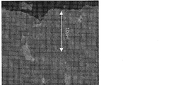
- FIG. 2 is a BEI (reflected electron beam image) of a cross section of sample 1 which is an example of the present invention
- FIG. 3 is a BEI (reflected electron beam image) of a cross section of sample 2 which is a comparative example.
- the BEI reflected electron beam image
- sample 2 in sample 2, a layer having a thickness of about 10 ⁇ m on the surface of the RTB-based sintered magnet (in the image of FIG. 3, the brightness on the magnet surface). High layer).
- the RH diffusion source and the RTB-based sintered magnet are welded by repeatedly contacting and separating the RH diffusion source and the RTB-based sintered magnet in a heat treatment furnace at 820 ° C.
- the heavy rare earth element RH is efficiently diffused from the RH diffusion source to the RTB-based sintered magnet, so that it is considered that there is no significant difference in the improvement of the magnetic characteristics.
- Example 2 (Sample 4) Nd: 19.8, Pr: 5.6, Dy: 4.3, B: 0.93, Co: 2.0, Cu: 0.1, Al: 0.14, Ga: 0.08, balance: An RTB-based sintered magnet was obtained under the same conditions as Sample 1, except that an alloy blended so as to have a composition of Fe (mass%) was used.
- the amount of TRE (A) from the surface layer of the RTB-based rare earth sintered magnet to 500 ⁇ m from the surface layer to the center is from the surface layer of the sintered magnet formed by completing the RH diffusion, the first heat treatment, and the second heat treatment. A 500 ⁇ m region was cut out toward the center and analyzed by ICP.
- the amount of TRE (B) at the center of the RTB-based rare earth sintered magnet was analyzed by ICP after cutting the center (50 mm 3 ) of the RTB-based sintered magnet that had been diffused.
- the central portion is a portion cut out by 50 mm 3 from the center of the RTB-based rare earth sintered magnet so as to be similar to the RTB-based sintered magnet.
- the amount of TRE from the surface layer of the RTB-based rare earth sintered magnet to 500 ⁇ m from the surface layer to the center is 31.1% by mass, and the amount of TRE at the center is 30.5% by mass.
- the difference between the amount of TRE up to 500 ⁇ m from the surface layer of the RTB-based rare earth sintered magnet toward the center and the amount of TRE in the center was 0.6.
- the amount of TRE from the surface layer of the RTB-based rare earth sintered magnet to 500 ⁇ m from the surface layer to the center is 30.5% by mass
- the amount of TRE in the center is 29.7% by mass
- the difference between the amount of TRE up to 500 ⁇ m from the surface layer to the center of the TB rare earth sintered magnet and the amount of TRE in the center was 0.8.
- the amount of TRE from the surface layer of the RTB-based rare earth sintered magnet to 500 ⁇ m from the surface layer to the center is 31.2% by mass
- the amount of TRE at the center is 30.5% by mass
- the difference between the amount of TRE up to 500 ⁇ m from the surface layer to the center of the TB rare earth sintered magnet and the amount of TRE in the center was 0.7.
- the amount of TRE from the surface layer of the RTB rare earth sintered magnet to 500 ⁇ m from the surface layer to the center is 32.2% by mass, and the amount of TRE in the center is 30.5% by mass.
- the difference between the amount of TRE up to 500 ⁇ m from the surface layer of the RTB rare earth sintered magnet toward the center and the amount of TRE in the center was 1.7.
- Sample 2 Sample 5 and Sample 8, which are comparative examples, all have a difference between the amount of TRE from the surface layer of the RTB-based rare earth sintered magnet to 500 ⁇ m and the amount of TRE at the center. It exceeded 1.0.
- Sample 4 Since Sample 4 originally had no concentrated layer, it was 0.3 g / m 2 or less at 25 hours, 50 hours, and 75 hours, and the amount of wear at 100 hours was 0.5 g / m 2 . This was almost the same amount of wear as Sample 6. On the other hand, in sample 5, since the removed 10 ⁇ m from the surface layer is concentrated layer, 25 hours depleting amount 0.6 g / m 2, in 1.0 g / m 2, 100 hours 50 hours 1.8 g / m 2 The amount of wear is much higher than that of sample 6. In Sample 5, it is considered that the amount of wear increased because of the rare earth concentrated layer on the surface of the RTB-based sintered magnet, which was easily oxidized.
- Sample 7 originally had no concentrated layer, so that it was 0.3 g / m 2 or less at 25 hours, 50 hours, and 75 hours, and the amount of wear at 100 hours was 0.5 g / m 2. The amount of wear was almost the same.
- Example 3 (Sample 10) Nd: 30.5, Pr: 0.1, B: 1.0, Co: 0.9, Cu: 0.1, Al: 0.2, Ga: 0.1, balance: Fe (mass%) RH diffusion was performed under the same conditions as Sample 1 except that an alloy blended so as to have a composition was used and a sphere having a diameter of 3 mm or less composed of 99.9% by mass of Tb was used as the RH diffusion source. An RTB-based sintered magnet was obtained.
- Magnetic properties Samples 10 and 11 were pulse magnetized at 3 MA / m, and then measured for magnetic properties (residual magnetic flux density: B r , coercive force: H cJ ) with a BH tracer. became.
- the produced sintered magnet is one after 10 ⁇ m is removed by shot blasting in order to remove impurities on the surface layer.
- sample 10 had an improved coercive force without lowering the residual magnetic flux density as compared with sample 11.
- sample 10 which is an example of the present invention
- a small amount of heavy rare earth element RH is efficiently diffused into the RTB-based sintered magnet.
- a heavy rare earth element film is hardly formed on the surface layer of the RTB rare earth sintered magnet.
- the RH diffusion source and the RTB-based sintered magnet are changed by repeatedly contacting and separating the RH diffusion source and the RTB-based sintered magnet in a heat treatment furnace at 820 ° C. It is considered that there is no significant difference in the improvement of the magnetic characteristics because the heavy rare earth element RH is efficiently diffused from the RH diffusion source to the RTB-based sintered magnet by direct contact without welding.
- the amount of TRE (A) from the surface layer of the RTB-based rare earth sintered magnet to 500 ⁇ m from the surface layer to the center is from the surface layer of the sintered magnet formed by completing the RH diffusion, the first heat treatment, and the second heat treatment. A 500 ⁇ m region was cut out toward the center and analyzed by ICP.
- the amount of TRE (B) at the center of the RTB-based rare earth sintered magnet was analyzed by ICP after cutting the center (50 mm 3 ) of the RTB-based sintered magnet that had been diffused.
- the central portion is a portion cut out by 50 mm 3 from the center of the RTB-based rare earth sintered magnet so as to be similar to the RTB-based sintered magnet.
- the amount of TRE from the surface layer of the RTB-based rare earth sintered magnet to 500 ⁇ m from the surface layer to the center is 31.1% by mass, and the amount of TRE in the center is 30.6% by mass.
- the difference between the amount of TRE up to 500 ⁇ m from the surface layer to the center of the RTB-based rare earth sintered magnet and the amount of TRE in the center was 0.5.
- the amount of TRE from the surface layer of the RTB-based rare earth sintered magnet to 500 ⁇ m from the surface layer to the center is 30.4% by mass, and the amount of TRE in the center is 29.5% by mass.
- the difference between the amount of TRE up to 500 ⁇ m from the surface layer to the center of the RTB-based rare earth sintered magnet and the amount of TRE in the center was 0.9.
- the amount of TRE from the surface layer of the RTB-based rare earth sintered magnet to 500 ⁇ m from the surface to the center is 31.5% by mass, and the amount of TRE in the center is 30.8% by mass.
- the difference between the amount of TRE up to 500 ⁇ m from the surface layer of the RTB-based rare earth sintered magnet toward the center and the amount of TRE in the center was 0.7.
- the amount of wear at 25 hours, 50 hours, and 75 hours was 0.5 g / m 2 or less, and the amount of wear at 100 hours was 0.7 g / m 2 . . This was almost the same amount of wear as sample 11. Since Sample 12 originally had no concentrated layer, it was 0.3 g / m 2 or less at 25 hours, 50 hours, and 75 hours, and the amount of wear at 100 hours was 0.5 g / m 2 . This was almost the same amount of wear as the sample 13. Sample 14 originally has no concentrated layer, so that it was 0.3 g / m 2 or less at 25 hours, 50 hours, and 75 hours, and the amount of wear at 100 hours was 0.5 g / m 2. The amount of wear was almost the same.
- an RTB-based sintered magnet having a high residual magnetic flux density and a high coercive force can be produced.
- the sintered magnet of the present invention is suitable for various motors such as a motor for mounting on a hybrid vehicle exposed to high temperatures, home appliances, and the like.
Landscapes
- Engineering & Computer Science (AREA)
- Chemical & Material Sciences (AREA)
- Mechanical Engineering (AREA)
- Materials Engineering (AREA)
- Metallurgy (AREA)
- Organic Chemistry (AREA)
- Power Engineering (AREA)
- Manufacturing & Machinery (AREA)
- Hard Magnetic Materials (AREA)
- Manufacturing Cores, Coils, And Magnets (AREA)
- Powder Metallurgy (AREA)
Abstract
Description
まず、本発明の好ましい実施形態では、重希土類元素RHの拡散の対象とするR-T-B系焼結磁石体を用意する。このR-T-B系焼結磁石体は、以下の組成からなる。
B(Bの一部はCで置換されていてもよい):5~8原子%
添加元素M(Al、Ti、V、Cr、Mn、Ni、Cu、Zn、Ga、Zr、Nb、Mo、Ag、In、Sn、Hf、Ta、W、Pb、およびBiからなる群から選択された少なくとも1種):0~2原子%
T(Feを主とする遷移金属であって、Coを含んでもよい)および不可避不純物:残部
ここで、希土類元素Rは、主として軽希土類元素RL(Nd、Pr)から選択される少なくとも1種の元素であるが、重希土類元素を含有していてもよい。なお、重希土類元素を含有する場合は、DyおよびTbの少なくとも一方を含むことが好ましい。
RH拡散源は、DyおよびTbの少なくとも1種からなる重希土類元素RHまたはそれらを含有する合金であり、その形態は、例えば、球状、線状、板状、ブロック状、粉末など任意である。ボールやワイヤ形状を有する場合、その直径は例えば数mm~数cmに設定され得る。粉末の場合、その粒径は、例えば、0.05mm以上5mm以下の範囲に設定され得る。このように、RH拡散源の形状・大きさは、特に限定されない。
本発明の実施形態では、R-T-B系焼結磁石体とRH拡散源に加えて、攪拌補助部材を処理室内に導入することが好ましい。攪拌補助部材はRH拡散源とR-T-B系焼結磁石体との接触を促進し、また攪拌補助部材に一旦付着した重希土類元素RHをR-T-B系焼結磁石体へ間接的に供給する役割をする。さらに、攪拌補助部材は、処理室内において、R-T-B系焼結磁石体同士やR-T-B系焼結磁石体とRH拡散源との接触による欠けを防ぐ役割もある。
図1を参照しながら、本発明の磁石を製造するための拡散処理工程の好ましい例を説明する。
RH拡散工程後に、拡散された重希土類元素RHをより均質化する目的でR-T-B系焼結磁石体1に対する第1熱処理を行っても良い。第1熱処理は、RH拡散源を取り除いた後、重希土類元素RHが実質的に拡散し得る700℃以上1000℃以下の範囲で行い、より好ましくは850℃以上950℃以下の温度で実行される。この第1熱処理では、R-T-B系焼結磁石体1に対して重希土類元素RHの更なる供給は生じないが、R-T-B系焼結磁石体1内部において重希土類元素RHの拡散が生じるため、焼結磁石の表面側から奥深くに重希土類元素RHを拡散し、磁石全体として保磁力を高めることが可能になる。第1熱処理の時間は、例えば10分以上72時間以下である。好ましくは1時間以上12時間以下である。ここで、第1熱処理を行なう熱処理炉の雰囲気圧力は、大気圧以下である。好ましいのは100kPa以下である。
また、保磁力を高めるために必要に応じてさらに第2熱処理(400℃以上700℃以下)を行ってもよい。第1熱処理(700℃以上1000℃以下)および第2熱処理(400℃以上700℃以下)を両方行う場合は、第1熱処理(700℃以上1000℃以下)の後に行うことが好ましい。第1熱処理(700℃以上1000℃以下)と第2熱処理(400℃以上700℃以下)とは、同じ処理室内で行っても良い。第2熱処理の時間は、10分以上72時間以下である。好ましくは1時間から12時間である。ここで、第2熱処理を行なう熱処理炉の雰囲気圧力は、大気圧以下である。好ましいのは100kPa以下である。なお、第1熱処理を行わず、第2熱処理だけでもよい。
(サンプル1)
まず、Nd:30.5、B:1.0、Co:0.9、Cu:0.1、Al:0.2、残部:Fe(質量%)の組成を有するように配合した合金を用いてストリップキャスト法により厚さ0.2から0.3mmの合金薄片を作製した。
まず、Nd:30.5、B:1.0、Co:0.9、Cu:0.1、Al:0.2、残部:Fe(質量%)の組成を有するように配合した合金を用いてストリップキャスト法により厚さ0.2から0.3mmの合金薄片を作製した。
まず、Nd:30.5、B:1.0、Co:0.9、Cu:0.1、Al:0.2、残部:Fe(質量%)の組成を有するように配合した合金を用いてストリップキャスト法により厚さ0.2から0.3mmの合金薄片を作製した。
サンプル1、サンプル2について、EPMA(島津製作所製)により内部へのDy、Nd、Feの拡散状況を比べた。図2は、本発明の実施例であるサンプル1の断面のBEI(反射電子線像)であり、図3は、比較例であるサンプル2の断面のBEI(反射電子線像)である。図3の断面のBEI(反射電子線像)から明らかなように、サンプル2では、R-T-B系焼結磁石表面に厚さ10μm程度の層(図3の像では、磁石表面における明度の高い層)があった。EPMAの評価結果より、この層にはDy、Ndが含まれており、希土類元素の濃縮層であることが確認された。一方、サンプル1では、図2から明らかなように、R-T-B系焼結磁石表面に希土類元素の濃縮層が確認されなかった。
サンプル1、サンプル2、サンプル3について、3MA/mのパルス着磁を行った後、B-Hトレーサにて磁気特性(残留磁束密度:Br、保磁力:HcJ)を測定し、表1の結果となった。ここで、作製した焼結磁石は、表層の不純物を取り除くため10μmだけショットブラストにて除去した後のものである。

(サンプル4)
Nd:19.8、Pr:5.6、Dy:4.3、B:0.93、Co:2.0、Cu:0.1、Al:0.14、Ga:0.08、残部:Fe(質量%)の組成を有するように配合した合金を用いたことを除き、サンプル1と同じ条件でR-T-B系焼結磁石を得た。
Nd:19.8、Pr:5.6、Dy:4.3、B:0.93、Co:2.0、Cu:0.1、Al:0.14、Ga:0.08、残部:Fe(質量%)の組成を有するように配合した合金を用いたことを除き、サンプル2と同じ条件でR-T-B系焼結磁石を得た。
Nd:19.8、Pr:5.6、Dy:4.3、B:0.93、Co:2.0、Cu:0.1、Al:0.14、Ga:0.08、残部:Fe(質量%)の組成を有するように配合した合金を用いたことを除き、サンプル3と同じ条件でR-T-B系焼結磁石を得た。
Nd:30.0、Dy:0.5、B:1.0、Co:0.9、Cu:0.1、Al:0.1、残部:Fe(質量%)を有するように配合した合金を用いたことを除き、サンプル1と同じ条件でR-T-B系焼結磁石を得た。
Nd:30.0、Dy:0.5、B:1.0、Co:0.9、Cu:0.1、Al:0.1、残部:Fe(質量%)を有するように配合した合金を用いたことを除き、サンプル2と同じ条件でR-T-B系焼結磁石を得た。
Nd:30.0、Dy:0.5、B:1.0、Co:0.9、Cu:0.1、Al:0.1、残部:Fe(質量%)を有するように配合した合金を用いたことを除き、サンプル3と同じ条件でR-T-B系焼結磁石を得た。
R-T-B系希土類焼結磁石の表層から中心部に向かって500μmまでのTRE量(A)とR-T-B系希土類焼結磁石の中心部のTRE量(B)とを測定した。測定した結果を表2にまとめた。

PCT試験(125℃×85%RH-0.2MPa)を行い、耐食性を比較した。ここで、PCT試験に用いた焼結磁石は、磁石表面から10μm、ショットブラストによって表面層を除去した後のものである。試験結果を表3に示す。

(サンプル10)
Nd:30.5、Pr:0.1、B:1.0、Co:0.9、Cu:0.1、Al:0.2、Ga:0.1、残部:Fe(質量%)の組成を有するように配合した合金を用いたことと、RH拡散源に99.9質量%のTbからなる直径3mm以下の球状体を用いたことを除きサンプル1と同じ条件でRH拡散をし、R-T-B系焼結磁石を得た。
Nd:30.5、Pr:0.1、B:1.0、Co:0.9、Cu:0.1、Al:0.2、Ga:0.1、残部:Fe(質量%)の組成を有するように配合した合金を用いたことを除きサンプル3と同じ条件でR-T-B系焼結磁石体を得た。
サンプル10、サンプル11について、3MA/mのパルス着磁を行った後、B-Hトレーサにて磁気特性(残留磁束密度:Br、保磁力:HcJ)を測定し、表4の結果となった。ここで、作製した焼結磁石は、表層の不純物を取り除くため10μmだけショットブラストにて除去した後のものである。

(サンプル12)
Nd:19.8、Pr:5.3、Dy:4.4、B:0.93、Co:2.0、Cu:0.1、Al:0.14、Ga:0.08、残部:Fe(質量%)を有するように配合した合金を用いたことを除き、サンプル10と同じ条件でR-T-B系焼結磁石を得た。
Nd:19.8、Pr:5.3、Dy:4.4、B:0.93、Co:2.0、Cu:0.1、Al:0.14、Ga:0.08、残部:Fe(質量%)を有するように配合した合金を用いたことを除き、サンプル11と同じ条件でR-T-B系焼結磁石を得た。
Nd:30.2、Dy:0.6、B:1.0、Co:0.9、Cu:0.1、Al:0.1、残部:Fe(質量%)を有するように配合した合金を用いたことを除き、サンプル10と同じ条件でR-T-B系焼結磁石を得た。
Nd:30.2、Dy:0.6、B:1.0、Co:0.9、Cu:0.1、Al:0.1、残部:Fe(質量%)を有するように配合した合金を用いたことを除き、サンプル11と同じ条件でR-T-B系焼結磁石を得た。
R-T-B系希土類焼結磁石の表層から中心部に向かって500μmまでのTRE量(A)とR-T-B系希土類焼結磁石の中心部のTRE量(B)とを測定した。測定した結果を表5にまとめた。

PCT試験(125℃×85%RH-0.2MPa)を行い、耐食性を比較した。ここで、PCT試験に用いた焼結磁石は、磁石表面から10μm、ショットブラストによって表面層を除去した後のものである。試験結果を表6に示す。

2 RH拡散源
3 ステンレス製の筒(処理室)
4 ヒータ
5 蓋
6 排気装置
Claims (2)
- 軽希土類元素RL(NdおよびPrの少なくとも1種を含む)を主たる希土類元素Rとして含有するR2Fe14B型化合物結晶粒を主相として有し、重希土類元素RH(Dy、Tbの少なくとも1種を含む)を含有するR-T-B系希土類焼結磁石であって、
前記R-T-B系希土類焼結磁石の表層を除去する前において、R-T-B系希土類焼結磁石の表層に希土類元素Rの濃縮層を有さず、
かつ
R-T-B系希土類焼結磁石の表層から中心部に向かって、保磁力が漸減する部位を有し、
前記R-T-B系希土類焼結磁石の表層から中心部に向かって500μmまでのTRE量と前記R-T-B系希土類焼結磁石の中心部のTRE量との差が0.1以上1.0以下である、R-T-B系希土類焼結磁石。 - 前記R-T-B系希土類焼結磁石のTRE量は28.5質量%から32.0質量%である請求項1に記載のR-T-B系希土類焼結磁石。
Priority Applications (4)
| Application Number | Priority Date | Filing Date | Title |
|---|---|---|---|
| CN201280005902.3A CN103329220B (zh) | 2011-01-19 | 2012-01-19 | R-t-b系烧结磁体 |
| JP2012553762A JP5929766B2 (ja) | 2011-01-19 | 2012-01-19 | R−t−b系焼結磁石 |
| US13/980,133 US9837193B2 (en) | 2011-01-19 | 2012-01-19 | R-T-B sintered magnet |
| EP12737001.3A EP2667385A4 (en) | 2011-01-19 | 2012-01-19 | R-t-b sintered magnet |
Applications Claiming Priority (2)
| Application Number | Priority Date | Filing Date | Title |
|---|---|---|---|
| JP2011008434 | 2011-01-19 | ||
| JP2011-008434 | 2011-01-19 |
Publications (1)
| Publication Number | Publication Date |
|---|---|
| WO2012099188A1 true WO2012099188A1 (ja) | 2012-07-26 |
Family
ID=46515810
Family Applications (1)
| Application Number | Title | Priority Date | Filing Date |
|---|---|---|---|
| PCT/JP2012/051038 WO2012099188A1 (ja) | 2011-01-19 | 2012-01-19 | R-t-b系焼結磁石 |
Country Status (5)
| Country | Link |
|---|---|
| US (1) | US9837193B2 (ja) |
| EP (1) | EP2667385A4 (ja) |
| JP (1) | JP5929766B2 (ja) |
| CN (1) | CN103329220B (ja) |
| WO (1) | WO2012099188A1 (ja) |
Cited By (7)
| Publication number | Priority date | Publication date | Assignee | Title |
|---|---|---|---|---|
| JP2016096182A (ja) * | 2014-11-12 | 2016-05-26 | Tdk株式会社 | R−t−b系焼結磁石 |
| JP2017073465A (ja) * | 2015-10-07 | 2017-04-13 | Tdk株式会社 | R−t−b系焼結磁石 |
| JP2018093202A (ja) * | 2016-12-06 | 2018-06-14 | Tdk株式会社 | R−t−b系永久磁石 |
| JP2018093201A (ja) * | 2016-12-06 | 2018-06-14 | Tdk株式会社 | R−t−b系永久磁石 |
| JP2019102707A (ja) * | 2017-12-05 | 2019-06-24 | Tdk株式会社 | R−t−b系永久磁石 |
| JP2019102708A (ja) * | 2017-12-05 | 2019-06-24 | Tdk株式会社 | R−t−b系永久磁石 |
| JP2022115921A (ja) * | 2016-12-06 | 2022-08-09 | Tdk株式会社 | R-t-b系永久磁石 |
Families Citing this family (11)
| Publication number | Priority date | Publication date | Assignee | Title |
|---|---|---|---|---|
| JP5284394B2 (ja) * | 2011-03-10 | 2013-09-11 | 株式会社豊田中央研究所 | 希土類磁石およびその製造方法 |
| RU2704989C2 (ru) * | 2015-03-31 | 2019-11-01 | Син-Эцу Кемикал Ко., Лтд. | Спеченный магнит r-fe-b и способ его изготовления |
| JP6380652B2 (ja) * | 2015-07-30 | 2018-08-29 | 日立金属株式会社 | R−t−b系焼結磁石の製造方法 |
| JP6724865B2 (ja) | 2016-06-20 | 2020-07-15 | 信越化学工業株式会社 | R−Fe−B系焼結磁石及びその製造方法 |
| CN109478452B (zh) * | 2016-08-17 | 2020-06-16 | 日立金属株式会社 | R-t-b系烧结磁体 |
| JP6614084B2 (ja) | 2016-09-26 | 2019-12-04 | 信越化学工業株式会社 | R−Fe−B系焼結磁石の製造方法 |
| CN108154988B (zh) * | 2016-12-06 | 2020-10-23 | Tdk株式会社 | R-t-b系永久磁铁 |
| CN110168680B (zh) * | 2017-01-26 | 2021-10-22 | 日产自动车株式会社 | 烧结磁体的制造方法 |
| JP2023510819A (ja) * | 2020-01-21 | 2023-03-15 | 福建省長汀金龍希土有限公司 | R-Fe-B系焼結磁石及びその粒界拡散処理方法 |
| CN112908672B (zh) * | 2020-01-21 | 2024-02-09 | 福建省金龙稀土股份有限公司 | 一种R-Fe-B系稀土烧结磁体的晶界扩散处理方法 |
| CN113345708B (zh) * | 2021-06-18 | 2023-02-17 | 安徽大地熊新材料股份有限公司 | 热处理设备及钕铁硼磁体的扩散方法 |
Citations (8)
| Publication number | Priority date | Publication date | Assignee | Title |
|---|---|---|---|---|
| JP2004296973A (ja) | 2003-03-28 | 2004-10-21 | Kenichi Machida | 金属蒸気収着による高性能希土類磁石の製造 |
| WO2007102391A1 (ja) | 2006-03-03 | 2007-09-13 | Hitachi Metals, Ltd. | R-Fe-B系希土類焼結磁石およびその製造方法 |
| WO2009107397A1 (ja) * | 2008-02-28 | 2009-09-03 | 日立金属株式会社 | R-Fe-B系希土類焼結磁石の製造方法およびその方法によって製造された希土類焼結磁石 |
| JP2009289994A (ja) | 2008-05-29 | 2009-12-10 | Tdk Corp | 磁石の製造方法 |
| WO2010109760A1 (ja) * | 2009-03-27 | 2010-09-30 | 株式会社日立製作所 | 焼結磁石及びそれを用いた回転電機 |
| WO2011004894A1 (ja) * | 2009-07-10 | 2011-01-13 | インターメタリックス株式会社 | NdFeB焼結磁石及びその製造方法 |
| WO2011007758A1 (ja) * | 2009-07-15 | 2011-01-20 | 日立金属株式会社 | R-t-b系焼結磁石の製造方法およびr-t-b系焼結磁石 |
| WO2012008426A1 (ja) * | 2010-07-12 | 2012-01-19 | 日立金属株式会社 | R-t-b系焼結磁石の製造方法 |
Family Cites Families (4)
| Publication number | Priority date | Publication date | Assignee | Title |
|---|---|---|---|---|
| MY142024A (en) * | 2005-03-23 | 2010-08-16 | Shinetsu Chemical Co | Rare earth permanent magnet |
| CN101006534B (zh) * | 2005-04-15 | 2011-04-27 | 日立金属株式会社 | 稀土类烧结磁铁及其制造方法 |
| JP4831074B2 (ja) * | 2006-01-31 | 2011-12-07 | 日立金属株式会社 | R−Fe−B系希土類焼結磁石およびその製造方法 |
| CN101651038B (zh) * | 2006-03-03 | 2012-06-06 | 日立金属株式会社 | 扩散处理装置 |
-
2012
- 2012-01-19 US US13/980,133 patent/US9837193B2/en active Active
- 2012-01-19 EP EP12737001.3A patent/EP2667385A4/en not_active Withdrawn
- 2012-01-19 JP JP2012553762A patent/JP5929766B2/ja active Active
- 2012-01-19 CN CN201280005902.3A patent/CN103329220B/zh active Active
- 2012-01-19 WO PCT/JP2012/051038 patent/WO2012099188A1/ja active Application Filing
Patent Citations (8)
| Publication number | Priority date | Publication date | Assignee | Title |
|---|---|---|---|---|
| JP2004296973A (ja) | 2003-03-28 | 2004-10-21 | Kenichi Machida | 金属蒸気収着による高性能希土類磁石の製造 |
| WO2007102391A1 (ja) | 2006-03-03 | 2007-09-13 | Hitachi Metals, Ltd. | R-Fe-B系希土類焼結磁石およびその製造方法 |
| WO2009107397A1 (ja) * | 2008-02-28 | 2009-09-03 | 日立金属株式会社 | R-Fe-B系希土類焼結磁石の製造方法およびその方法によって製造された希土類焼結磁石 |
| JP2009289994A (ja) | 2008-05-29 | 2009-12-10 | Tdk Corp | 磁石の製造方法 |
| WO2010109760A1 (ja) * | 2009-03-27 | 2010-09-30 | 株式会社日立製作所 | 焼結磁石及びそれを用いた回転電機 |
| WO2011004894A1 (ja) * | 2009-07-10 | 2011-01-13 | インターメタリックス株式会社 | NdFeB焼結磁石及びその製造方法 |
| WO2011007758A1 (ja) * | 2009-07-15 | 2011-01-20 | 日立金属株式会社 | R-t-b系焼結磁石の製造方法およびr-t-b系焼結磁石 |
| WO2012008426A1 (ja) * | 2010-07-12 | 2012-01-19 | 日立金属株式会社 | R-t-b系焼結磁石の製造方法 |
Non-Patent Citations (1)
| Title |
|---|
| See also references of EP2667385A4 |
Cited By (7)
| Publication number | Priority date | Publication date | Assignee | Title |
|---|---|---|---|---|
| JP2016096182A (ja) * | 2014-11-12 | 2016-05-26 | Tdk株式会社 | R−t−b系焼結磁石 |
| JP2017073465A (ja) * | 2015-10-07 | 2017-04-13 | Tdk株式会社 | R−t−b系焼結磁石 |
| JP2018093202A (ja) * | 2016-12-06 | 2018-06-14 | Tdk株式会社 | R−t−b系永久磁石 |
| JP2018093201A (ja) * | 2016-12-06 | 2018-06-14 | Tdk株式会社 | R−t−b系永久磁石 |
| JP2022115921A (ja) * | 2016-12-06 | 2022-08-09 | Tdk株式会社 | R-t-b系永久磁石 |
| JP2019102707A (ja) * | 2017-12-05 | 2019-06-24 | Tdk株式会社 | R−t−b系永久磁石 |
| JP2019102708A (ja) * | 2017-12-05 | 2019-06-24 | Tdk株式会社 | R−t−b系永久磁石 |
Also Published As
| Publication number | Publication date |
|---|---|
| CN103329220A (zh) | 2013-09-25 |
| US20130293328A1 (en) | 2013-11-07 |
| EP2667385A1 (en) | 2013-11-27 |
| JP5929766B2 (ja) | 2016-06-08 |
| EP2667385A4 (en) | 2018-04-04 |
| CN103329220B (zh) | 2016-08-24 |
| JPWO2012099188A1 (ja) | 2014-06-30 |
| US9837193B2 (en) | 2017-12-05 |
Similar Documents
| Publication | Publication Date | Title |
|---|---|---|
| JP5929766B2 (ja) | R−t−b系焼結磁石 | |
| JP5831451B2 (ja) | R−t−b系焼結磁石の製造方法 | |
| JP5510457B2 (ja) | R−t−b系焼結磁石の製造方法 | |
| TWI509642B (zh) | Rare earth permanent magnet and its manufacturing method | |
| JP5880448B2 (ja) | R−t−b系焼結磁石の製造方法 | |
| JP5999106B2 (ja) | R−t−b系焼結磁石の製造方法 | |
| JP6391915B2 (ja) | Nd−Fe−B系磁石の粒界改質方法 | |
| JP5348124B2 (ja) | R−Fe−B系希土類焼結磁石の製造方法およびその方法によって製造された希土類焼結磁石 | |
| WO2007102391A1 (ja) | R-Fe-B系希土類焼結磁石およびその製造方法 | |
| JP2004296973A (ja) | 金属蒸気収着による高性能希土類磁石の製造 | |
| KR20110002441A (ko) | 희토류 자석의 제조 방법 및 희토류 자석 | |
| JP6443179B2 (ja) | R−t−b系焼結磁石の製造方法 | |
| JP2012079726A (ja) | R−t−b−m系焼結磁石用合金の製造方法およびr−t−b−m系焼結磁石の製造方法 | |
| JP5209349B2 (ja) | NdFeB焼結磁石の製造方法 | |
| JP5850052B2 (ja) | Rh拡散源およびそれを用いたr−t−b系焼結磁石の製造方法 | |
| JP5643355B2 (ja) | NdFeB焼結磁石の製造方法 | |
| JP2011101043A (ja) | R−Fe−B系希土類焼結磁石およびその製造方法 | |
| JP5668491B2 (ja) | R−t−b系焼結磁石の製造方法 | |
| JP5854304B2 (ja) | R−t−b系焼結磁石の製造方法 | |
| JP2023151499A (ja) | 希土類磁石の製造方法 |
Legal Events
| Date | Code | Title | Description |
|---|---|---|---|
| 121 | Ep: the epo has been informed by wipo that ep was designated in this application |
Ref document number: 12737001 Country of ref document: EP Kind code of ref document: A1 |
|
| ENP | Entry into the national phase |
Ref document number: 2012553762 Country of ref document: JP Kind code of ref document: A |
|
| WWE | Wipo information: entry into national phase |
Ref document number: 13980133 Country of ref document: US |
|
| NENP | Non-entry into the national phase |
Ref country code: DE |
|
| WWE | Wipo information: entry into national phase |
Ref document number: 2012737001 Country of ref document: EP |