WO2012091065A1 - Pneumatique - Google Patents
Pneumatique Download PDFInfo
- Publication number
- WO2012091065A1 WO2012091065A1 PCT/JP2011/080334 JP2011080334W WO2012091065A1 WO 2012091065 A1 WO2012091065 A1 WO 2012091065A1 JP 2011080334 W JP2011080334 W JP 2011080334W WO 2012091065 A1 WO2012091065 A1 WO 2012091065A1
- Authority
- WO
- WIPO (PCT)
- Prior art keywords
- tire
- continuous ribbon
- width
- continuous
- ribbon
- Prior art date
Links
Images


Classifications
-
- B—PERFORMING OPERATIONS; TRANSPORTING
- B60—VEHICLES IN GENERAL
- B60C—VEHICLE TYRES; TYRE INFLATION; TYRE CHANGING; CONNECTING VALVES TO INFLATABLE ELASTIC BODIES IN GENERAL; DEVICES OR ARRANGEMENTS RELATED TO TYRES
- B60C19/00—Tyre parts or constructions not otherwise provided for
- B60C19/002—Noise damping elements provided in the tyre structure or attached thereto, e.g. in the tyre interior
-
- B—PERFORMING OPERATIONS; TRANSPORTING
- B29—WORKING OF PLASTICS; WORKING OF SUBSTANCES IN A PLASTIC STATE IN GENERAL
- B29D—PRODUCING PARTICULAR ARTICLES FROM PLASTICS OR FROM SUBSTANCES IN A PLASTIC STATE
- B29D30/00—Producing pneumatic or solid tyres or parts thereof
- B29D30/0061—Accessories, details or auxiliary operations not otherwise provided for
-
- Y—GENERAL TAGGING OF NEW TECHNOLOGICAL DEVELOPMENTS; GENERAL TAGGING OF CROSS-SECTIONAL TECHNOLOGIES SPANNING OVER SEVERAL SECTIONS OF THE IPC; TECHNICAL SUBJECTS COVERED BY FORMER USPC CROSS-REFERENCE ART COLLECTIONS [XRACs] AND DIGESTS
- Y10—TECHNICAL SUBJECTS COVERED BY FORMER USPC
- Y10T—TECHNICAL SUBJECTS COVERED BY FORMER US CLASSIFICATION
- Y10T152/00—Resilient tires and wheels
- Y10T152/10—Tires, resilient
- Y10T152/10495—Pneumatic tire or inner tube
Definitions
- the present invention relates to a pneumatic tire, and more particularly, to a pneumatic tire provided with a sound damping body for suppressing cavity resonance generated in a tire lumen.
- Resonant vibration (cavity resonance) in the tire lumen is generated by vibration of air blocked in the tire lumen.
- the air in the tire lumen is excited by the deformation of the tire tread and sidewalls accompanying the rolling of the tire, and the air trapped in the annular lumen acts as an air column by the excitation. .
- the sound wave excited in the tire lumen is transmitted to the vehicle interior as a solid propagation sound that propagates through the wheel, suspension device, and automobile body, and is recognized as a low-frequency sound that is uncomfortable for the vehicle occupant.
- FIG. A technique has been disclosed in which the sound-absorbing body is fixed to the tire inner surface so as to extend in the tire rotation direction to reduce cavity resonance noise. Further, in FIG. 1 of Patent Document 2, by having two substantially trapezoidal shapes, a sponge noise control body provided with a trough in the middle is fixed to the tire inner surface so as to extend in the tire rotation direction.
- a technique for reducing cavity resonance is disclosed.
- FIG. 1 of Patent Document 3 a plurality of independent ribbon-shaped sound absorbers are fixed to the tire inner surface so as to extend in the tire rotation direction, thereby reducing both cavity resonance noise and high-speed durability. Such a technique is disclosed.
- Patent Document 1 and Patent Document 2 attach the sound absorber to the tire inner surface in order to reduce cavity resonance noise.
- the high-speed durability of the tire is lowered when covering a wide range such as about 40%.
- Patent Document 3 the process is complicated because the sound damping body must be introduced a plurality of times when the sound damping body is attached to the inner surface of the tire, and the productivity of such a tire is reduced. There is a problem of doing.
- the present invention has been made to solve the above-described problems of the prior art, and it is possible to control the tire lumen, which can maintain high-speed durability and productivity while reducing cavity resonance noise.
- An object is to provide a pneumatic tire provided with a sound body.
- the present invention provides a pneumatic tire having a tread, a lumen surrounded by an inner surface of the tire, and a sound control body for reducing cavity resonance sound of the lumen.
- the sound damping body is formed of a predetermined sound damping material, and has a width fixed to the tire inner surface so as to cover at least 30% of the tire radial inner surface corresponding to the tread. W and thickness E, and at least one continuous ribbon having a bottom surface that is in close contact with the inner surface of the tire having a width Wc.
- the at least one continuous ribbon has one or more rounds around the tire rotation axis.
- the start and end of at least one continuous ribbon are offset from each other in the direction of the axis of rotation of the tire, whereby the at least one adjacent ribbon and the tire inner surface Is continuous groove is formed with a groove width D is 10% or more of the width W of at least one continuous ribbon, and wherein the width Wc of the bottom surface of the continuous ribbon is smaller than the width W of the continuous ribbon.
- the continuous groove is formed by the continuous ribbon between the adjacent continuous ribbons and the inner surface of the tire, so that the air vibration of the tire lumen is guided to the continuous groove.
- the continuous groove is formed by a continuous ribbon whose start and end are offset in the axial direction and the inner surface of the tire has one or more rounds around the rotation axis of the tire, the propagation direction of air vibration (tire circumferential direction) The direction in which the continuous ribbon extends differs, and as a result, the propagation of air vibrations in the tire lumen is hindered by the continuous groove, and the cavity resonance sound is improved.
- the energy of the air vibration introduced into the continuous groove is divided into a component penetrating into the continuous ribbon and a component reflected on the surface of the continuous groove of the continuous ribbon.
- the energy component penetrating into the continuous ribbon is attenuated by the sound-damping effect of the continuous ribbon, which is a sound control body, and the component reflected on the continuous groove surface of the continuous ribbon is not only attenuated by the reflection, but also other components of the continuous ribbon. Since the penetration and reflection phenomenon described above is repeated when the energy reaches the portion, the cavity resonance can be improved more effectively.
- a continuous groove is formed by the continuous ribbon and the tire inner surface, and the groove width is 10% or more of the width W of the continuous ribbon. Therefore, the tire inner surface is directly inside the tire via the continuous groove. The area of the cavity that is in contact with the air can be made sufficient for heat dissipation. Therefore, even if a noise control body is provided, heat generated mainly by the tread during tire rolling can be reliably released from the tire inner surface to the tire lumen, and as a result, high speed durability can be maintained. I can do it.
- the width Wc of the bottom surface of the continuous ribbon that is in close contact with the tire inner surface is smaller than the width W of the continuous ribbon, so that the tire inner surface directly contacts the air in the tire lumen through the continuous groove.
- the area can be increased. Therefore, even if a noise control body is provided, heat generated mainly by the tread when the tire rolls can be released more reliably from the tire inner surface to the tire lumen, and as a result, high-speed durability can be more reliably ensured. Can be maintained.
- the continuous ribbon when the continuous ribbon is fixed to the tire lumen, for example, the starting end is fixed to the tire inner surface, and then the tire is rotated around the tire rotation axis.
- the continuous ribbon or the tire itself may be fixed to the end of the continuous ribbon while moving in the axial direction. As described above, the continuous ribbon can be attached relatively easily, and the productivity of the tire provided with the sound absorber can be maintained.
- the ratio (W / Wc) of the width W of at least one continuous ribbon to the width Wc of the bottom surface is preferably 1.2 or more.
- the ratio (W / Wc) of the width W of the continuous ribbon to the width Wc of the bottom surface is smaller than 1.2, the area where the tire inner surface directly contacts the air in the tire lumen through the continuous groove is reduced. Durability will be reduced. Therefore, if the ratio (W / Wc) of the width W of the continuous ribbon to the width Wc of the bottom surface is 1.2 or more, high-speed durability is more reliably ensured and productivity is maintained while reducing cavity resonance noise. I can do it.
- the tread preferably has a width TW, and the width W of at least one continuous ribbon is not less than 5% and not more than 25% of the width TW of the tread.
- the width W of at least one continuous ribbon is not less than 5% and not more than 25% of the width TW of the tread.
- the width W of the continuous ribbon is larger than 25% of the width TW of the tread, the proportion of the tire inner surface occupied by the continuous ribbon increases, and the proportion of the tire inner surface that comes into contact with the air in the tire lumen decreases. As a result, the high-speed durability decreases. Therefore, when the width W of the continuous ribbon is 5% to 25% of the width TW of the tread, high-speed durability can be ensured and productivity can be maintained while reducing cavity resonance noise.
- At least one continuous ribbon is arranged so as to make two or more rounds of the tire inner surface.
- the continuous groove formed by the continuous ribbon is formed at least one round, it is possible to obtain effective damping of air vibration, and as a result, more reliably, the cavity High speed durability can be ensured while reducing resonance noise.
- At least one continuous ribbon is two, and in each of the two continuous ribbons, a continuous groove is formed by the continuous ribbon and the tire inner surface.
- the position for fixing the continuous ribbon on the tire inner surface can be set to an optimum position for suppressing the cavity resonance noise, and the degree of freedom for installing the continuous ribbon is increased. High-speed durability can be ensured while reducing the cavity resonance noise more effectively.
- At least one continuous ribbon is two, and one of the two continuous ribbons has a predetermined angular direction with respect to the tire circumferential direction around the tire rotation axis.
- the other continuous ribbon extends around the tire rotation axis along a predetermined angular direction in which one continuous ribbon extends and a direction symmetrical to the tire circumferential direction.
- the position for fixing the continuous ribbon on the tire inner surface can be set to an optimum position for suppressing the cavity resonance noise, and the degree of freedom for installing the continuous ribbon is increased. High-speed durability can be ensured while reducing the cavity resonance noise more effectively.
- the predetermined sound damping material of at least one continuous ribbon is selected from any one of sponge, foamed rubber composition, glass wool, rock wool, and cellulose fiber. Since these materials are excellent in vibration proofing and sound damping properties, it is possible to reduce cavity resonance noise.
- the thickness E of at least one continuous ribbon is not less than 50% and not more than 200% of the width W of at least one continuous ribbon.
- the cavity resonance can be more effectively reduced. That is, if the thickness E of the continuous ribbon is smaller than 50% of the width W of the continuous ribbon, the thickness E of the continuous ribbon is insufficient to prevent the propagation of sound waves of air vibrations in the tire lumen. The degree of reduction of the resonance sound will decrease. On the other hand, if the thickness E of the continuous ribbon is larger than 200% of the width W of the continuous ribbon, the sound-damping effect due to the continuous ribbon will reach its peak, which adversely affects the cost and weight of the tire. Therefore, if the thickness E of the continuous ribbon is 50% to 200% of the width W of the continuous ribbon, the cavity resonance noise can be reduced more efficiently.
- the groove width D of the continuous groove varies in the range of 10% or more and 250% or less of the width W of at least one continuous ribbon along the direction in which at least one continuous ribbon extends. Formed.
- the cavity resonance sound can be reduced more effectively. High-speed durability can be secured and productivity can be maintained.
- the pneumatic tire according to the present invention can maintain high-speed durability and productivity while reducing cavity resonance noise.
- FIG. 1 is a diagram schematically showing a radial cross section of a pneumatic tire provided with a sound damping body according to the first embodiment of the present invention
- FIG. 2 is a sound damping body according to the first embodiment of the present invention. It is a figure showing typically a tire inside surface of a pneumatic tire provided with.
- the circumferential direction of the tire is indicated by YY ′
- the axial direction of the tire is indicated by XX ′.
- reference numeral 1 denotes a pneumatic tire 1 provided with a sound damper 4 according to the first embodiment of the present invention.
- the damping body 4 is for reducing cavity resonance noise, and is composed of a continuous ribbon 41 having a width W and a thickness E as shown in FIGS. It is attached to the inner surface 2 of the pneumatic tire at the bottom surface that is in close contact.
- the “tire internal surface” (tire internal surface 2) refers to a surface facing the inner cavity of the tire, and is a surface that cannot be seen from the outside in a normal tire use state (attached to a wheel). That's it.
- the continuous ribbon 41 is formed of one continuous continuous ribbon 41 and has an angle with respect to the circumferential direction of the tire, that is, extends in an oblique direction with respect to the circumferential direction of the tire. It is continuously attached to the tire inner surface 2. With such continuous attachment of one continuous ribbon 41 over four laps, the continuous groove 5 having a groove width D extending over three laps by the adjacent continuous ribbon 41 and the tire inner surface 2 becomes the tire inner surface 2. Is formed. As shown in FIG. 2, the continuous groove 5 formed in this way also extends so as to have an angle with respect to the circumferential direction of the tire.
- the continuous ribbon 41 is attached so as to extend along a predetermined angle with respect to the circumferential direction of the tire, and the continuous groove 5 is formed by the adjacent continuous ribbon 41 and the tire inner surface 2.
- the width W of the continuous ribbon 41 is the maximum width projected on the tire inner surface 2
- the thickness E is the maximum thickness in the tire radial direction
- Wc is a width that is in close contact with the tire inner surface 2 to which the continuous ribbon 41 is attached and is projected onto the tire inner surface 2 in a portion parallel to the tire inner surface 2, and the width D of the continuous groove formed by the continuous ribbon 41 is This is the distance between the maximum widths projected on the tire inner surface 2 of the adjacent continuous ribbons 41.
- the tire 1 has a tread surface 3 having a width TW that contacts a road surface during rolling.
- the tire size in this example is 225 / 55R16.
- the width W of the continuous ribbon 41 is formed to be 5% to 25% of the width TW of the tread 3.
- the width TW of the tread 3 is 168 mm, and the width W of the continuous ribbon 41 is 24 mm.
- the thickness E of the continuous ribbon 41 is formed to be 50% to 200% of the width W of the continuous ribbon 41. In the present embodiment, the thickness E of the continuous ribbon 41 is 15 mm.
- the width Wc of the bottom surface closely contacting the tire inner surface of the continuous ribbon 41 is formed to be smaller than the width W of the continuous ribbon 41. Further, the ratio (W / Wc) of the width W of the continuous ribbon 41 to the width Wc of the bottom surface that is in close contact with the inner surface of the tire is 1.2 or more. In this embodiment, the width Wc of the bottom surface that is in close contact with the tire inner surface of the continuous ribbon 41 is 18 mm, and the ratio of the width W of the continuous ribbon 41 to the width Wc of the bottom surface that is in close contact with the tire inner surface (W / Wc). Is 1.3. In order to secure the fixing of the sound damper during rolling of the tire, the ratio (W / Wc) of the width W of the continuous ribbon to the width Wc of the bottom surface is preferably 3.0 or less.
- the continuous ribbon 41 is made of a sound-damping material having excellent vibration-proofing and sound-damping properties.
- the continuous ribbon 41 is preferably a single continuous ribbon, but a plurality of short ribbons can be combined to form a single continuous ribbon.
- the sound-damping material forming the continuous ribbon 41 is preferably selected from any one of sponge, foamed rubber composition, glass wool, rock wool, and cellulose fiber.
- the continuous ribbon 41 of this embodiment is made of sponge.
- the sponge may be formed into a predetermined shape outside the tire in advance into the tire lumen to form the continuous ribbon 41, or the sponge may be formed, for example, a polyurethane material may be directly applied to the tire lumen.
- the continuous ribbon 41 may be formed while being introduced (injected). Further, when the above-described polyurethane-based material for forming the continuous ribbon 41 is introduced directly into the tire lumen, the material growth occurs on the material surface and inside due to the difference between the material temperature and the environmental temperature in the process of forming the continuous ribbon 41. There is a case where a difference in rate occurs and a thin film-like portion is formed on the surface of the material. Such a film-like portion existing on the surface of the continuous ribbon 41 can prevent water from penetrating into the continuous ribbon 41 and improve the durability of the continuous ribbon 41.
- the continuous ribbon 41 is fixed to the tire inner surface 2 so as to occupy at least 30% of the range of the tire inner surface 2 corresponding to the range in which the tread 3 inside the tread 3 in the radial direction is formed.
- the continuous ribbon 41 occupies a range of 85% inside the tread 3 in the radial direction, that is, the continuous ribbon 41 covers 85% of the range corresponding to the tread 3 on the tire inner surface 2.
- the tire inner surface 2 is fixed.
- the width D of the continuous groove 5 is formed to be 10% or more of the width W of the continuous ribbon 41. In the present embodiment, the width D of the continuous groove 5 is 13 mm.
- the continuous ribbon 41 shown in the radial cross-sectional view shown in FIG. 1 is formed by only one continuous ribbon 41 as described above. As shown in FIG. 2, two continuous ribbons 41 of the start end 411 and the end end 412 are formed. These two ends are offset from each other in the axial direction of the tire, i.e., separated from each other. In this embodiment, the offset amounts of both end portions 411 and 412 are 148 mm.
- the continuous ribbon 41 attached to the inner surface 2 of the tire has two ends, that is, a start end 411 and a end end 412 as shown in FIG. 412 are offset from each other in the axial direction.
- the continuous ribbon 41 is provided on the tire inner surface 2 so as to extend around the four circumferences of the single continuous ribbon 41 as described above, that is, to extend along the predetermined angle with respect to the tire circumferential direction.
- a continuous groove 5 is formed over three circumferences by the adjacent continuous ribbon 41 and the tire inner surface 2.
- the continuous ribbon 41 is rotated four times in the tire circumferential direction so that the start end 411 and the end end 412 are offset on the axial line on the tire inner surface 2 as shown in FIG.
- the start end 411 and the end end 412 are arranged at positions shifted with respect to the tire circumferential direction, for example, in the case of three and a half laps in the tire circumferential direction.
- the continuous ribbon 41 may be provided so that the start end 411 and the end end 412 are offset in the axial direction at a position different from the direction line.
- the cross-sectional shape of the continuous ribbon 41 is a trapezoid having an upper bottom as a bottom surface, but the cross-sectional shape is not limited to a trapezoid having an upper bottom as a bottom surface.
- the cross-sectional shape of the continuous ribbon 41 may be a cross-sectional shape that allows the width Wc of the bottom surface that forms the continuous groove 5 and is in close contact with the tire inner surface to be smaller than the width W of the continuous ribbon 41.
- the outer shape other than the bottom surface that is in close contact with the tire inner surface can be changed as appropriate, such as an arch-shaped cross-sectional shape, and the side surface and the upper surface bulge in a curved shape.
- the width W of the continuous ribbon (41) is the maximum width projected on the tire inner surface 2
- the thickness E is the maximum thickness in the tire radial direction
- the width Wc of the bottom surface that is in close contact with the surface is a width that is in close contact with the tire inner surface 2 to which the continuous ribbon is attached and is projected onto the tire inner surface 2 in a portion parallel to the tire inner surface 2, and is formed continuously by the continuous ribbon.
- the width D of the groove is an interval between the maximum widths projected on the tire inner surface 2 of adjacent continuous ribbons.
- the continuous ribbon may be formed to meander along a predetermined angle with respect to the tire circumferential direction so that a continuous groove is formed. In this case, the width D of the continuous groove may be changed continuously along the direction in which the continuous ribbon extends, or the meandering shape of adjacent continuous ribbons is arranged so that the width D of the continuous groove is constant. May be.
- the continuous ribbon 41 is formed so as to have an angle with respect to the circumferential direction of the tire so as to prevent the propagation of sound waves of the resonant cavity sound traveling in the circumferential direction of the tire. Can be reduced.
- the cavity resonance sound is generated when air confined in an annular lumen acts as an air column during rolling of the tire, and such cavity resonance sound is mainly generated in the tire column around the tire column. Caused by air vibrations propagating in the direction. Therefore, by disposing the continuous ribbon 41 so as to extend obliquely along a predetermined angle with respect to the tire circumferential direction, the cavity resonance noise can be effectively reduced.
- the cavity resonance sound guided into the continuous groove 5 is mainly used in the tire circumferential direction.
- the energy of the air vibration propagating to is divided into a component that penetrates into the continuous ribbon 41 and a component that reflects on the surface of the continuous ribbon 41.
- the energy component that has penetrated into the continuous ribbon 41 is attenuated by the effect of the sound-damping material forming the continuous ribbon 41, and the component reflected on the surface of the continuous ribbon 41 is not only attenuated by the reflection, but also of the continuous ribbon 41. Since the penetration and reflection phenomenon is repeated when the energy arrives at the other part, the cavity resonance can be effectively reduced.
- the groove width D of the continuous groove 5 is set to 10% or more of the width W of the continuous ribbon, the area where the tire inner surface directly contacts the air in the tire lumen through the continuous groove is radiated. A sufficient area can be obtained. Furthermore, since the width Wc of the bottom surface of the continuous ribbon 41 that is in close contact with the tire inner surface is smaller than the width W of the continuous ribbon 41, the tire inner surface directly passes through the continuous groove through the continuous groove air for heat dissipation. The area that touches can be further increased.
- the continuous ribbon 41 that is the sound damper 4 is provided with a plurality of rounds (four rounds in the present embodiment) inside the tread 3 in the radial direction, heat generated mainly in the tread during tire rolling is generated from the tire inner surface. It is possible to reliably discharge into the tire lumen, and as a result, high-speed durability can be maintained.
- one continuous ribbon 41 is fixed to the tire lumen by making four turns so as to extend obliquely with respect to the tire circumferential direction, for example, as the fixing method, continuous After the start end 411 of the ribbon 41 is fixed to the tire inner surface, the continuous ribbon 41 or the tire 1 itself is moved in the axial direction while the tire 1 is rotated around the tire rotation axis, and is continuously fixed to the end 412 of the continuous ribbon 41. That's fine.
- the continuous ribbon 41 can be attached relatively easily, and the tire 1 provided with the continuous ribbon 41 that is the sound control body 4. Productivity can be maintained.
- the width W of the continuous ribbon 41 is formed to be 5% to 25% of the width TW of the tread 3.
- the width W of the continuous ribbon 41 becomes too small, and the rotational speed of the continuous ribbon is effective for reducing the cavity resonance noise efficiently. Need to be increased, and productivity will be reduced.
- the width W of the continuous ribbon 41 is larger than 25% of the width TW of the tread, the ratio of the tire inner surface 2 occupied by the continuous ribbon increases, so that the tire inner surface 2 comes into contact with the air in the tire lumen. Since the ratio decreases, the high-speed durability decreases. Therefore, if the width W of the continuous ribbon 41 is 5% to 25% of the width TW of the tread, high-speed durability can be ensured and productivity can be maintained while reducing cavity resonance noise.
- the thickness E of the continuous ribbon 41 is formed to be 50% to 200% of the width W of the continuous ribbon 41.
- the thickness E of the continuous ribbon 41 is smaller than 50% of the width W of the continuous ribbon 41, the thickness E of the continuous ribbon 41 is insufficient to prevent the propagation of sound waves of air vibrations in the tire lumen. For this reason, the degree of reduction of the cavity resonance sound is reduced.
- the thickness E of the continuous ribbon 41 is larger than 200% of the width W of the continuous ribbon 41, the sound-damping effect of the continuous ribbon 41 will reach its peak, which will adversely affect the cost and weight of the tire. . Therefore, if the thickness E of the continuous ribbon 41 is 50% to 200% of the width W of the continuous ribbon 41, the cavity resonance noise can be reduced more efficiently and the increase in cost and weight can be suppressed. I can do it.
- FIG. 3 is a view schematically showing a tire inner surface of a pneumatic tire provided with a sound damper according to the second embodiment of the present invention. Since the basic configuration and effects of the second embodiment are the same as those of the first embodiment described above, the configuration and effects different from those of the first embodiment will be mainly described here. Description of similar configurations and effects is omitted.
- two continuous ribbons 41 and 42 are attached so as to make three rounds of the inner surface 2 of the pneumatic tire 1.
- These two continuous ribbons 41 and 42 are inclined in the same direction with respect to the tire circumferential direction, and continuous grooves 5 similar to those of the first embodiment are formed.
- the continuous grooves 5 formed by the two continuous ribbons 41 and 42 and the tire inner surface 2 are formed so as to have the same width D.
- the degree of freedom of the attachment position of the continuous ribbon 41 to the tire inner surface 2 is improved, and it is possible to select and attach the most effective place for attenuation of the cavity resonance sound. is there.
- the inclinations of the two continuous ribbons 41 with respect to the tire circumferential direction can be made different from each other, and the width D of the continuous groove 5 can be made different for each continuous ribbon 41.
- FIG. 4 is a view schematically showing a tire inner surface of a pneumatic tire provided with a sound damping body according to a third embodiment of the present invention. Since the basic configuration and effects of the third embodiment are the same as those of the first embodiment described above, here, the configuration and effects different from those of the first embodiment will be mainly described. Description of similar configurations and effects is omitted.
- two continuous ribbons 41 and 42 are attached so as to make three rounds around the inner surface 2 of the pneumatic tire 1.
- one continuous ribbon 41 extends in an oblique direction with respect to the tire circumferential direction around the rotation axis, as in the first embodiment, and the other continuous ribbon 42 has one continuous ribbon 41.
- the extending direction is attached so as to extend around the rotation axis in a direction symmetrical to the tire circumferential direction.
- Both continuous ribbons 41 and 42 form a continuous groove 5 together with the tire inner surface 2 as in the first embodiment, and the continuous grooves 5 formed on the continuous ribbons 41 and 42 and the tire inner surface 2 are the same. It has a width D.
- This third embodiment also improves the degree of freedom of the attachment position of the continuous ribbon 41 to the tire inner surface 2 and enables the attachment of the most effective place for attenuation of the cavity resonance sound. It is.
- the inclinations of the two continuous ribbons 41 can be made different, and the width D of the continuous groove 5 can also be made different for each continuous ribbon 41.
- FIG. 5 is a view schematically showing a tire inner surface of a pneumatic tire provided with a sound damper according to the fourth embodiment of the present invention. Since the basic configuration and effects of the fourth embodiment are the same as those of the first embodiment described above, the configuration and effects different from those of the first embodiment will be mainly described here. Description of similar configurations and effects is omitted.
- one continuous ribbon 41 is attached so as to go around the inner surface 2 of the pneumatic tire 1 and is formed by the continuous ribbon 41 and the tire inner surface 2.
- the continuous groove 5 is formed such that the groove width D is different for each turn.
- the groove width D of the continuous groove 5 varies between 15 mm and 54 mm.
- channel 5 change continuously along the direction where the continuous ribbon 41 is extended.
- the cavity resonance sound can be reduced more efficiently.
- the energy of the air vibration of the cavity resonance sound guided into the continuous groove 5 irregularly penetrates into the continuous ribbon 41 inside the continuous groove 5 or repeatedly reflects on the surface of the continuous ribbon 41.
- the cavity resonance is improved more effectively.
- the change in the groove width D of the continuous groove 5 is realized by changing the attachment direction of the continuous ribbon 41 for each turn, but the change in the groove width D of the continuous groove 5 is: For example, it may be realized by attaching the continuous ribbon 41 to the tire inner surface 2 so as to zigzag or meander, or may be performed by other methods such as making the width W of the continuous ribbon 41 variable ( Not shown).
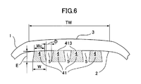
- FIG. 6 is a diagram schematically showing a radial cross section of a pneumatic tire provided with a sound damper according to the fifth embodiment of the present invention. Since the basic configuration and effects of the fifth embodiment are the same as those of the first embodiment described above, here, the configuration and effects different from those of the first embodiment will be mainly described. Description of similar configurations and effects is omitted.
- a single continuous ribbon 41 having a trapezoidal cross-sectional shape with the upper base as a bottom surface and a thickness E of 50 to 200% of the width W is formed at the start end and the end end.
- the width W of the continuous ribbon 41 is 24 mm
- the thickness E is 25 mm, which is 104% of the width W
- the width Wc of the bottom surface is 18 mm
- the thickness E of the continuous ribbon 41 is relatively thicker than that of the first embodiment within the range of 50 to 200% of the width W.
- the cavity resonance sound is more effective. Improved.
- FIG. 7 is a diagram schematically showing a radial cross section of a pneumatic tire provided with a sound damper according to the sixth embodiment of the present invention. Since the basic configuration and effects of the sixth embodiment are the same as those of the first embodiment described above, the configuration and effects different from those of the first embodiment will be mainly described here. Description of similar configurations and effects is omitted.
- the cross-sectional shape of the continuous ribbon 41 is such that the ratio (W / Wc) of the width W to the width Wc of the bottom surface closely contacting the tire inner surface is 1.2 or more.
- One continuous ribbon 41 formed in an arch shape (for example, a cross-sectional shape such as “kamaboko” as shown in the figure) has a start end and an end offset in the axial direction, and the tire inner surface 2 is rotated around the tire rotation axis.
- a continuous groove 5 similar to that of the first embodiment is formed.
- the width W of the continuous ribbon 41 is 24 mm
- the thickness E is 15 mm
- the width Wc of the bottom surface is 18 mm
- the groove width D of the continuous groove 5 is 15 mm.
- the cross-sectional shape of the continuous ribbon 41 is an arch shape as described above, the area of the tire inner surface that directly contacts the air in the tire lumen through the continuous groove is secured to ensure heat dissipation.
- the center of gravity of the continuous ribbon 41 can be made closer to the tire inner surface 2 than the trapezoidal continuous ribbon having the upper base as the bottom as described above.
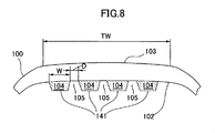
- FIG. 8 is a diagram schematically showing a radial cross section of a pneumatic tire provided with a sound damping body according to the prior art.
- the tire size in FIG. 8 is the same as that of the pneumatic tire 1 according to the first embodiment.
- a ribbon 141 made of a sound damper 104 for reducing cavity resonance noise is attached to the inner surface 102 of the pneumatic tire 100 according to the conventional technology.
- the ribbon 141 is a continuous ribbon that extends four times in the tire circumferential direction so that the continuous groove 105 is formed, and is attached so that two ends thereof are offset.
- the cross-sectional shape of the continuous ribbon 141 is a trapezoid whose bottom is the bottom surface closely contacting the tire inner surface 102, and the width of the bottom is the same as the maximum width W of the continuous ribbon 141.
- the ribbon 141 has a width of 24 mm and a thickness of 15 mm.
- Example 1 (first embodiment) of the present invention.
- the verification results obtained by using a simulation (finite element method) using commercially available computer software will be described.
- the tire size of the tire model according to the conventional example, the comparative example, and the example 1 was 225 / 55R16, the wheel size was 7.0 J ⁇ 16, the internal pressure was 230 kPa, and the load was set to 542 daN.
- the tire model corresponding to FIG. 8 is used as a comparative example, and the continuous ribbon 41 of the model according to Example 1 is set so that the cross-sectional area of the ribbon 43 is the same, and the material used for the continuous ribbon 41 is used. was set to the same.
- the noise level of the tire model was simulated using the point sound source in the tire lumen with the rim, internal pressure, and load.
- the calculated noise is expressed as an index of the sound pressure level with respect to the conventional example as the sound pressure level to which the A filter is applied in the frequency band between 190 and 230 Hz including the primary peak of the cavity resonance sound. Larger numbers are better.
- the tire model was simulated with the rim, internal pressure, and load, the maximum temperature within the radial inner range corresponding to the tread, near the tire inner surface when the tire was rotated at 80 km / h. .
- the calculated maximum temperature is indicated by an index with respect to the conventional example. Larger numbers are better.
Landscapes
- Engineering & Computer Science (AREA)
- Mechanical Engineering (AREA)
- Tires In General (AREA)
Abstract
Priority Applications (6)
| Application Number | Priority Date | Filing Date | Title |
|---|---|---|---|
| US13/976,489 US20140020806A1 (en) | 2010-12-28 | 2011-12-27 | Pneumatic tire |
| BR112013014471A BR112013014471A8 (pt) | 2010-12-28 | 2011-12-27 | Pneu inflável |
| EA201390978A EA201390978A1 (ru) | 2010-12-28 | 2011-12-27 | Пневматическая шина |
| JP2012551025A JP5860411B2 (ja) | 2010-12-28 | 2011-12-27 | 空気入りタイヤ |
| EP11853082.3A EP2660075B1 (fr) | 2010-12-28 | 2011-12-27 | Pneumatique |
| CN201180063753.1A CN103298627B (zh) | 2010-12-28 | 2011-12-27 | 充气轮胎 |
Applications Claiming Priority (2)
| Application Number | Priority Date | Filing Date | Title |
|---|---|---|---|
| PCT/JP2010/073754 WO2012090310A1 (fr) | 2010-12-28 | 2010-12-28 | Pneumatique |
| JPPCT/JP2010/073754 | 2010-12-28 |
Publications (1)
| Publication Number | Publication Date |
|---|---|
| WO2012091065A1 true WO2012091065A1 (fr) | 2012-07-05 |
Family
ID=46382459
Family Applications (2)
| Application Number | Title | Priority Date | Filing Date |
|---|---|---|---|
| PCT/JP2010/073754 WO2012090310A1 (fr) | 2010-12-28 | 2010-12-28 | Pneumatique |
| PCT/JP2011/080334 WO2012091065A1 (fr) | 2010-12-28 | 2011-12-27 | Pneumatique |
Family Applications Before (1)
| Application Number | Title | Priority Date | Filing Date |
|---|---|---|---|
| PCT/JP2010/073754 WO2012090310A1 (fr) | 2010-12-28 | 2010-12-28 | Pneumatique |
Country Status (6)
| Country | Link |
|---|---|
| US (1) | US20140020806A1 (fr) |
| EP (1) | EP2660075B1 (fr) |
| CN (1) | CN103298627B (fr) |
| BR (1) | BR112013014471A8 (fr) |
| EA (1) | EA201390978A1 (fr) |
| WO (2) | WO2012090310A1 (fr) |
Cited By (6)
| Publication number | Priority date | Publication date | Assignee | Title |
|---|---|---|---|---|
| JP2015107692A (ja) * | 2013-12-03 | 2015-06-11 | 横浜ゴム株式会社 | 空気入りタイヤ |
| WO2015118707A1 (fr) * | 2014-02-07 | 2015-08-13 | 住友ゴム工業株式会社 | Bandage pneumatique à atténuateur de bruit et atténuateur de bruit pour pneus |
| JP2017210226A (ja) * | 2016-05-27 | 2017-11-30 | クムホ タイヤ シーオー.,インク. | 吸音材付き共鳴音低減タイヤ |
| JP2018520041A (ja) * | 2015-07-03 | 2018-07-26 | コンティネンタル・ライフェン・ドイチュラント・ゲゼルシャフト・ミト・ベシュレンクテル・ハフツング | 空気入り自動車タイヤ |
| CN108883674A (zh) * | 2016-03-29 | 2018-11-23 | 耐克森轮胎股份有限公司 | 充气轮胎 |
| WO2018230146A1 (fr) * | 2017-06-14 | 2018-12-20 | 株式会社ブリヂストン | Bandage pneumatique comprenant un élément d'absorption de bruit, et ensemble jante de pneu |
Families Citing this family (18)
| Publication number | Priority date | Publication date | Assignee | Title |
|---|---|---|---|---|
| DE112014005324T5 (de) * | 2013-11-21 | 2016-08-04 | The Yokohama Rubber Co., Ltd. | Luftreifen |
| JP6356552B2 (ja) * | 2014-09-16 | 2018-07-11 | 東芝メモリ株式会社 | 情報処理装置 |
| EP3212390B1 (fr) | 2014-10-29 | 2021-06-30 | Pirelli Tyre S.p.A. | Procédé et appareil d'application automatique d'un élément réducteur de bruit à un pneu pour roues de véhicule |
| KR101781946B1 (ko) * | 2015-12-07 | 2017-09-26 | 한국타이어 주식회사 | 공명음 저감용 공기입 타이어 및 이의 제조방법 |
| US20170185402A1 (en) * | 2015-12-23 | 2017-06-29 | Intel Corporation | Instructions and logic for bit field address and insertion |
| US20170242876A1 (en) * | 2016-02-22 | 2017-08-24 | Ca, Inc. | Maintaining Database Referential Integrity Using Different Primary and Foreign Key Values |
| US10864782B2 (en) | 2016-09-07 | 2020-12-15 | Bridgestone Americas Tire Operations, Llc | Devices for reducing tire noise |
| EP3544798B1 (fr) | 2016-11-22 | 2023-08-23 | Pirelli Tyre S.p.A. | Procédé et appareil destinés à l'application d'éléments réducteurs de bruit sur un pneu destiné à des roues de véhicule |
| IL253151B (en) * | 2017-06-25 | 2018-05-31 | Elan Amirav | Multipurpose tires |
| JP7229225B2 (ja) * | 2017-07-27 | 2023-02-27 | ピレリ・タイヤ・ソチエタ・ペル・アツィオーニ | 空洞騒音を減少することが可能なタイヤを製造するための方法及びそれによって得られるタイヤの組 |
| JP7173474B2 (ja) | 2018-05-15 | 2022-11-16 | ブリヂストン アメリカズ タイヤ オペレーションズ、 エルエルシー | 多層インサートを有するタイヤ |
| CN108773246A (zh) * | 2018-07-19 | 2018-11-09 | 三角轮胎股份有限公司 | 轮胎降噪扰流器 |
| EP4081413A1 (fr) * | 2019-12-26 | 2022-11-02 | Compagnie Generale Des Etablissements Michelin | Profil de mousse acoustique amélioré pour pneumatiques |
| KR102169474B1 (ko) * | 2020-07-16 | 2020-10-23 | 넥센타이어 주식회사 | 나선형 밴드 타입의 타이어용 흡음재 |
| DE102021103990A1 (de) | 2021-02-19 | 2022-08-25 | Promera Gmbh & Co. Kg | Reifen mit an seiner Innenseite angeordneter Schall-Absorberelemente |
| FR3120815B1 (fr) | 2021-03-22 | 2023-02-24 | Michelin & Cie | Pneumatique comprenant une structure de rigidification endurante et permettant une bonne mise a plat |
| FR3120817B1 (fr) | 2021-03-22 | 2024-03-29 | Michelin & Cie | Pneumatique comprenant une structure de rigidification endurante |
| FR3120816B1 (fr) | 2021-03-22 | 2023-02-10 | Michelin & Cie | Pneumatique comprenant une decoupure circonferentielle et une structure de rigidification endurante et permettant une mise a plat optimisee |
Citations (6)
| Publication number | Priority date | Publication date | Assignee | Title |
|---|---|---|---|---|
| WO2003103989A1 (fr) | 2002-06-05 | 2003-12-18 | 住友ゴム工業株式会社 | Ensemble pneumatique-jante, element insonorisant utilise avec cet ensemble et procede de stockage de pneumatiques |
| JP2005262920A (ja) | 2004-03-16 | 2005-09-29 | Sumitomo Rubber Ind Ltd | 空気入りタイヤとリムとの組立体 |
| WO2006013874A1 (fr) * | 2004-08-04 | 2006-02-09 | The Yokohama Rubber Co., Ltd. | Pneu |
| JP2007161069A (ja) | 2005-12-13 | 2007-06-28 | Sumitomo Rubber Ind Ltd | 制音具付空気入りタイヤ |
| JP2010000947A (ja) * | 2008-06-20 | 2010-01-07 | Yokohama Rubber Co Ltd:The | タイヤ騒音低減装置 |
| JP2010280340A (ja) * | 2009-06-05 | 2010-12-16 | Yokohama Rubber Co Ltd:The | 空気入りタイヤ |
Family Cites Families (5)
| Publication number | Priority date | Publication date | Assignee | Title |
|---|---|---|---|---|
| DE60209053T2 (de) * | 2001-04-16 | 2006-09-28 | Sumitomo Rubber Industries Ltd., Kobe | Reifengeräusch reduzierende Vorrichtung |
| DE602004009533T2 (de) * | 2004-03-16 | 2008-07-24 | Sumitomo Rubber Industries Ltd., Kobe | Reifen mit Schalldämpfer |
| EP1659004B1 (fr) * | 2004-11-19 | 2012-02-01 | Sumitomo Rubber Industries, Ltd. | Assemblage de pneumatiques et de jantes comprenant un élément d'insonorisation dedans |
| JP4567423B2 (ja) * | 2004-11-19 | 2010-10-20 | 住友ゴム工業株式会社 | タイヤの制音具 |
| JP4723342B2 (ja) * | 2005-10-06 | 2011-07-13 | 住友ゴム工業株式会社 | 空気入りタイヤとリムとの組立体 |
-
2010
- 2010-12-28 WO PCT/JP2010/073754 patent/WO2012090310A1/fr active Application Filing
-
2011
- 2011-12-27 WO PCT/JP2011/080334 patent/WO2012091065A1/fr active Application Filing
- 2011-12-27 BR BR112013014471A patent/BR112013014471A8/pt not_active Application Discontinuation
- 2011-12-27 US US13/976,489 patent/US20140020806A1/en not_active Abandoned
- 2011-12-27 EP EP11853082.3A patent/EP2660075B1/fr active Active
- 2011-12-27 EA EA201390978A patent/EA201390978A1/ru unknown
- 2011-12-27 CN CN201180063753.1A patent/CN103298627B/zh active Active
Patent Citations (6)
| Publication number | Priority date | Publication date | Assignee | Title |
|---|---|---|---|---|
| WO2003103989A1 (fr) | 2002-06-05 | 2003-12-18 | 住友ゴム工業株式会社 | Ensemble pneumatique-jante, element insonorisant utilise avec cet ensemble et procede de stockage de pneumatiques |
| JP2005262920A (ja) | 2004-03-16 | 2005-09-29 | Sumitomo Rubber Ind Ltd | 空気入りタイヤとリムとの組立体 |
| WO2006013874A1 (fr) * | 2004-08-04 | 2006-02-09 | The Yokohama Rubber Co., Ltd. | Pneu |
| JP2007161069A (ja) | 2005-12-13 | 2007-06-28 | Sumitomo Rubber Ind Ltd | 制音具付空気入りタイヤ |
| JP2010000947A (ja) * | 2008-06-20 | 2010-01-07 | Yokohama Rubber Co Ltd:The | タイヤ騒音低減装置 |
| JP2010280340A (ja) * | 2009-06-05 | 2010-12-16 | Yokohama Rubber Co Ltd:The | 空気入りタイヤ |
Non-Patent Citations (1)
| Title |
|---|
| See also references of EP2660075A4 |
Cited By (11)
| Publication number | Priority date | Publication date | Assignee | Title |
|---|---|---|---|---|
| JP2015107692A (ja) * | 2013-12-03 | 2015-06-11 | 横浜ゴム株式会社 | 空気入りタイヤ |
| WO2015118707A1 (fr) * | 2014-02-07 | 2015-08-13 | 住友ゴム工業株式会社 | Bandage pneumatique à atténuateur de bruit et atténuateur de bruit pour pneus |
| US10226970B2 (en) | 2014-02-07 | 2019-03-12 | Sumitomo Rubber Industries, Ltd. | Sound-suppressor-equipped pneumatic tire, and sound suppressor for tires |
| JP2018520041A (ja) * | 2015-07-03 | 2018-07-26 | コンティネンタル・ライフェン・ドイチュラント・ゲゼルシャフト・ミト・ベシュレンクテル・ハフツング | 空気入り自動車タイヤ |
| CN108883674A (zh) * | 2016-03-29 | 2018-11-23 | 耐克森轮胎股份有限公司 | 充气轮胎 |
| CN108883674B (zh) * | 2016-03-29 | 2020-11-24 | 耐克森轮胎股份有限公司 | 充气轮胎 |
| JP2017210226A (ja) * | 2016-05-27 | 2017-11-30 | クムホ タイヤ シーオー.,インク. | 吸音材付き共鳴音低減タイヤ |
| WO2018230146A1 (fr) * | 2017-06-14 | 2018-12-20 | 株式会社ブリヂストン | Bandage pneumatique comprenant un élément d'absorption de bruit, et ensemble jante de pneu |
| JP2019001285A (ja) * | 2017-06-14 | 2019-01-10 | 株式会社ブリヂストン | 吸音部材付き空気入りタイヤ、及びタイヤ・リム組立体 |
| CN110719849A (zh) * | 2017-06-14 | 2020-01-21 | 株式会社普利司通 | 带吸音构件的充气轮胎和轮胎轮辋组装体 |
| CN110719849B (zh) * | 2017-06-14 | 2022-04-08 | 株式会社普利司通 | 带吸音构件的充气轮胎和轮胎轮辋组装体 |
Also Published As
| Publication number | Publication date |
|---|---|
| WO2012090310A1 (fr) | 2012-07-05 |
| US20140020806A1 (en) | 2014-01-23 |
| EP2660075A4 (fr) | 2014-08-13 |
| EP2660075B1 (fr) | 2015-09-02 |
| EA201390978A1 (ru) | 2013-11-29 |
| BR112013014471A8 (pt) | 2017-12-26 |
| CN103298627A (zh) | 2013-09-11 |
| BR112013014471A2 (pt) | 2016-09-13 |
| EP2660075A1 (fr) | 2013-11-06 |
| CN103298627B (zh) | 2016-02-03 |
Similar Documents
| Publication | Publication Date | Title |
|---|---|---|
| WO2012091065A1 (fr) | Pneumatique | |
| JP4960966B2 (ja) | タイヤ騒音低減装置及び空気入りタイヤ | |
| JP4785820B2 (ja) | タイヤとリムの組立体 | |
| JP6536402B2 (ja) | 空気入りタイヤ | |
| JP5961309B1 (ja) | ハブ取付部のボルト孔間にキャビティーが形成された自動車ホイール | |
| JP3612059B2 (ja) | 空気入りタイヤとリムの組立体 | |
| JP2008080969A (ja) | 空気入りタイヤ及び車輪構造 | |
| JP5060790B2 (ja) | 空気入りタイヤ | |
| JP2009029348A (ja) | 車両用ホイール | |
| JP2009214613A (ja) | リムホイール | |
| JP5860411B2 (ja) | 空気入りタイヤ | |
| JP4533130B2 (ja) | 空気入りタイヤとリムとの組立体 | |
| JPWO2007114383A1 (ja) | 空気入りタイヤ | |
| JP2008308089A (ja) | 空気入りタイヤ | |
| JP2012171459A (ja) | 車両用ホイール | |
| KR101001822B1 (ko) | 저소음 공기입 타이어 | |
| JP5746546B2 (ja) | 空気入りタイヤとリムとの組立体 | |
| JP2009006831A (ja) | 空気入りタイヤ | |
| JP5076522B2 (ja) | 空気入りタイヤ | |
| JP5350854B2 (ja) | 空気入りタイヤ | |
| JP2006168637A (ja) | 空気入りタイヤ | |
| KR102247474B1 (ko) | 오목홈형 흡음부재를 구비한 공기입 타이어 | |
| JP2009029263A (ja) | 空気入りタイヤ | |
| JP5755927B2 (ja) | 空気入りタイヤ | |
| JP2009173066A (ja) | 空気入りタイヤ |
Legal Events
| Date | Code | Title | Description |
|---|---|---|---|
| 121 | Ep: the epo has been informed by wipo that ep was designated in this application |
Ref document number: 11853082 Country of ref document: EP Kind code of ref document: A1 |
|
| WWE | Wipo information: entry into national phase |
Ref document number: 2011853082 Country of ref document: EP |
|
| ENP | Entry into the national phase |
Ref document number: 2012551025 Country of ref document: JP Kind code of ref document: A |
|
| NENP | Non-entry into the national phase |
Ref country code: DE |
|
| WWE | Wipo information: entry into national phase |
Ref document number: 201390978 Country of ref document: EA |
|
| WWE | Wipo information: entry into national phase |
Ref document number: 13976489 Country of ref document: US |
|
| REG | Reference to national code |
Ref country code: BR Ref legal event code: B01A Ref document number: 112013014471 Country of ref document: BR |
|
| ENP | Entry into the national phase |
Ref document number: 112013014471 Country of ref document: BR Kind code of ref document: A2 Effective date: 20130610 |