WO2012090726A1 - 非水電解質二次電池 - Google Patents
非水電解質二次電池 Download PDFInfo
- Publication number
- WO2012090726A1 WO2012090726A1 PCT/JP2011/079161 JP2011079161W WO2012090726A1 WO 2012090726 A1 WO2012090726 A1 WO 2012090726A1 JP 2011079161 W JP2011079161 W JP 2011079161W WO 2012090726 A1 WO2012090726 A1 WO 2012090726A1
- Authority
- WO
- WIPO (PCT)
- Prior art keywords
- positive electrode
- negative electrode
- electrode tab
- tab
- battery
- Prior art date
- Legal status (The legal status is an assumption and is not a legal conclusion. Google has not performed a legal analysis and makes no representation as to the accuracy of the status listed.)
- Ceased
Links
Images


Classifications
-
- H—ELECTRICITY
- H01—ELECTRIC ELEMENTS
- H01M—PROCESSES OR MEANS, e.g. BATTERIES, FOR THE DIRECT CONVERSION OF CHEMICAL ENERGY INTO ELECTRICAL ENERGY
- H01M10/00—Secondary cells; Manufacture thereof
- H01M10/05—Accumulators with non-aqueous electrolyte
- H01M10/058—Construction or manufacture
- H01M10/0587—Construction or manufacture of accumulators having only wound construction elements, i.e. wound positive electrodes, wound negative electrodes and wound separators
-
- H—ELECTRICITY
- H01—ELECTRIC ELEMENTS
- H01M—PROCESSES OR MEANS, e.g. BATTERIES, FOR THE DIRECT CONVERSION OF CHEMICAL ENERGY INTO ELECTRICAL ENERGY
- H01M50/00—Constructional details or processes of manufacture of the non-active parts of electrochemical cells other than fuel cells, e.g. hybrid cells
- H01M50/50—Current conducting connections for cells or batteries
- H01M50/528—Fixed electrical connections, i.e. not intended for disconnection
-
- H—ELECTRICITY
- H01—ELECTRIC ELEMENTS
- H01M—PROCESSES OR MEANS, e.g. BATTERIES, FOR THE DIRECT CONVERSION OF CHEMICAL ENERGY INTO ELECTRICAL ENERGY
- H01M50/00—Constructional details or processes of manufacture of the non-active parts of electrochemical cells other than fuel cells, e.g. hybrid cells
- H01M50/50—Current conducting connections for cells or batteries
- H01M50/531—Electrode connections inside a battery casing
- H01M50/534—Electrode connections inside a battery casing characterised by the material of the leads or tabs
-
- H—ELECTRICITY
- H01—ELECTRIC ELEMENTS
- H01M—PROCESSES OR MEANS, e.g. BATTERIES, FOR THE DIRECT CONVERSION OF CHEMICAL ENERGY INTO ELECTRICAL ENERGY
- H01M50/00—Constructional details or processes of manufacture of the non-active parts of electrochemical cells other than fuel cells, e.g. hybrid cells
- H01M50/50—Current conducting connections for cells or batteries
- H01M50/531—Electrode connections inside a battery casing
- H01M50/538—Connection of several leads or tabs of wound or folded electrode stacks
-
- H—ELECTRICITY
- H01—ELECTRIC ELEMENTS
- H01M—PROCESSES OR MEANS, e.g. BATTERIES, FOR THE DIRECT CONVERSION OF CHEMICAL ENERGY INTO ELECTRICAL ENERGY
- H01M50/00—Constructional details or processes of manufacture of the non-active parts of electrochemical cells other than fuel cells, e.g. hybrid cells
- H01M50/50—Current conducting connections for cells or batteries
- H01M50/572—Means for preventing undesired use or discharge
- H01M50/584—Means for preventing undesired use or discharge for preventing incorrect connections inside or outside the batteries
- H01M50/586—Means for preventing undesired use or discharge for preventing incorrect connections inside or outside the batteries inside the batteries, e.g. incorrect connections of electrodes
-
- H—ELECTRICITY
- H01—ELECTRIC ELEMENTS
- H01M—PROCESSES OR MEANS, e.g. BATTERIES, FOR THE DIRECT CONVERSION OF CHEMICAL ENERGY INTO ELECTRICAL ENERGY
- H01M50/00—Constructional details or processes of manufacture of the non-active parts of electrochemical cells other than fuel cells, e.g. hybrid cells
- H01M50/50—Current conducting connections for cells or batteries
- H01M50/572—Means for preventing undesired use or discharge
- H01M50/584—Means for preventing undesired use or discharge for preventing incorrect connections inside or outside the batteries
- H01M50/59—Means for preventing undesired use or discharge for preventing incorrect connections inside or outside the batteries characterised by the protection means
- H01M50/595—Tapes
-
- Y—GENERAL TAGGING OF NEW TECHNOLOGICAL DEVELOPMENTS; GENERAL TAGGING OF CROSS-SECTIONAL TECHNOLOGIES SPANNING OVER SEVERAL SECTIONS OF THE IPC; TECHNICAL SUBJECTS COVERED BY FORMER USPC CROSS-REFERENCE ART COLLECTIONS [XRACs] AND DIGESTS
- Y02—TECHNOLOGIES OR APPLICATIONS FOR MITIGATION OR ADAPTATION AGAINST CLIMATE CHANGE
- Y02E—REDUCTION OF GREENHOUSE GAS [GHG] EMISSIONS, RELATED TO ENERGY GENERATION, TRANSMISSION OR DISTRIBUTION
- Y02E60/00—Enabling technologies; Technologies with a potential or indirect contribution to GHG emissions mitigation
- Y02E60/10—Energy storage using batteries
-
- Y—GENERAL TAGGING OF NEW TECHNOLOGICAL DEVELOPMENTS; GENERAL TAGGING OF CROSS-SECTIONAL TECHNOLOGIES SPANNING OVER SEVERAL SECTIONS OF THE IPC; TECHNICAL SUBJECTS COVERED BY FORMER USPC CROSS-REFERENCE ART COLLECTIONS [XRACs] AND DIGESTS
- Y02—TECHNOLOGIES OR APPLICATIONS FOR MITIGATION OR ADAPTATION AGAINST CLIMATE CHANGE
- Y02P—CLIMATE CHANGE MITIGATION TECHNOLOGIES IN THE PRODUCTION OR PROCESSING OF GOODS
- Y02P70/00—Climate change mitigation technologies in the production process for final industrial or consumer products
- Y02P70/50—Manufacturing or production processes characterised by the final manufactured product
Definitions
- the present invention relates to a non-aqueous electrolyte secondary battery, and more specifically, a non-aqueous electrolyte secondary battery in which the generation of a magnetic field due to a current flow during use is small and the influence of noise caused by the magnetic field on a hearing aid or the like is small. It relates to batteries.
- non-aqueous electrolyte secondary batteries represented by high-capacity lithium ion secondary batteries are widely used.
- non-aqueous electrolyte secondary batteries used for small devices are often used in a rectangular shape from the viewpoint of excellent space efficiency and ease of handling.
- These non-aqueous electrolyte secondary batteries generally include a positive electrode plate in which a positive electrode mixture containing a positive electrode active material that occludes and releases lithium ions is applied to both surfaces of a positive electrode core made of an elongated sheet-like aluminum foil. And a negative electrode plate in which a negative electrode mixture containing a negative electrode active material that occludes and releases lithium ions is applied to both surfaces of a negative electrode core made of an elongated sheet-like copper foil or the like.
- These positive electrode plate and negative electrode plate are arranged in a cylindrical or elliptical shape with a separator made of a microporous polyethylene film or the like interposed between them to form a wound electrode body. In the case of a battery, the wound electrode body is further crushed to form a flat shape.
- Patent Document 1 listed below discloses a square nonaqueous electrolyte secondary battery including such a flat wound electrode body.
- a configuration of a rectangular sealed battery 50 disclosed in Patent Document 1 will be described with reference to FIG.
- FIG. 7 is a perspective view of a main part of a rectangular sealed battery 50 disclosed in Patent Document 1 below.
- a spiral electrode body 51 formed by winding a positive electrode plate and a negative electrode plate with a separator interposed therebetween is housed in an aluminum battery exterior body 52 that also serves as a positive electrode external terminal. ing.
- the positive electrode plate is provided with a positive electrode core exposed portion (hereinafter referred to as “double-side exposed portion”) that does not have a positive electrode active material layer on both surfaces of the positive electrode core for a certain distance from the winding end of the positive electrode core. Further, only a certain distance from the double-sided exposed portion, the positive electrode core exposed portion (hereinafter referred to as “single-side exposed portion”) where only one side of the positive electrode core has a positive electrode active material layer and the other side of the core is exposed. ”) Is provided. In such a double-sided exposed portion, a substantially U-shaped cut portion is formed by three cut lines penetrating the core body, and the positive electrode current collecting tab 54 is formed by cutting up the cut portion.
- the spiral electrode body 51 is wound so that the single-side exposed portion of the positive electrode plate faces the outer peripheral side and the double-side exposed portion is positioned at the outermost peripheral portion of the spiral electrode body 51. This is for bringing the core body exposed portion and the battery outer body inner surface into contact with each other, and the contact between the core body exposed portion and the battery outer body inner surface electrically connects the battery outer body 52 serving as the positive electrode external terminal and the positive electrode. Connected.
- the battery outer body 52 is sealed by sealing the sealing plate 53 to the upper opening edge of the battery outer body 52.
- This welding is performed between the outer peripheral side surface of the sealing plate 3 and the inner side of the opening end of the battery outer body 52.
- Laser welding is performed with a positive electrode current collecting tab 54 led out from the positive electrode plate interposed therebetween.
- the negative electrode plate has a negative electrode current collector tab 55 electrically connected to the negative electrode core exposed portion formed at the winding start end by spot welding.
- the negative electrode current collector tab 55 is connected to the sealing plate 53. It is electrically connected to a fixed current collecting terminal plate 56.
- the adhesive tape 57 is affixed to the winding end part of the spiral electrode body 51, and has a structure that protects the positive electrode current collecting tab 54 to be cut and raised.
- the positive electrode current collecting tab 54 is formed of a foil piece obtained by cutting and raising a part of the positive electrode core exposed portion. Properties such as the mechanical strength of the tab 54 depend on the material properties of the positive electrode core. However, since an aluminum foil having a thickness of about several tens of ⁇ m is usually used as the positive electrode core, the sealed battery 50 disclosed in Patent Document 1 below has a low mechanical strength of the positive electrode current collecting tab 54. There are challenges.
- Patent Document 2 in order to solve the above-described problem of improving the mechanical strength of the positive electrode current collector tab, the cut and raised piece cut and raised from the exposed portion of the positive electrode core is used as it is as the positive electrode current collector tab.
- an invention of a rectangular sealed battery in which a foil piece having a mechanical strength higher than that of the positive electrode core is electrically connected to the cut and raised piece to form a positive electrode tab.
- the hearing aid has a function of capturing and amplifying external sound with a microphone, and a function of capturing and amplifying magnetic flux generated from the speaker portion of the telephone by an electromagnetic coil with an electromagnetic pickup (also referred to as “telephone pickup”). In particular, it is easily affected by external magnetic field noise.
- an electromagnetic pickup also referred to as “telephone pickup”. The reason why the hearing aid uses such an electromagnetic pickup is that when the sound output from the speaker of the telephone is picked up and amplified by the microphone of the hearing aid, ambient noise is picked up by the microphone, so that the clarity of the sound is lowered. Because.
- the magnetic field generated from the mobile phone tends to adversely affect the hearing aid. For this reason, even in a non-aqueous electrolyte secondary battery that is a power source of a mobile phone, it is desired to suppress the generation of a magnetic field due to the current flowing through the non-aqueous electrolyte secondary battery.
- a battery is current-collected by taking out the electric current obtained by the chemical reaction which arises in each of a positive electrode plate and a negative electrode plate with a positive electrode tab or a negative electrode tab. Therefore, in a battery, it is generally considered that if the current flowing through the positive electrode plate and the current flowing through the negative electrode plate are reversed, the magnetic fields due to the respective currents cancel each other out, so that the magnetic field can be reduced.
- the positions of the positive electrode tab or the negative electrode tab are both set to the winding start side or the winding end side of the respective electrode plates and are arranged at positions overlapping or close to each other, the current flowing directions are parallel in opposite directions. Therefore, it is theoretically possible to reduce the magnetic field caused by the current flowing in the active material formation region of the positive electrode plate and the negative electrode plate.
- the present inventor has arranged the positions of the positive electrode tab and the negative electrode tab so that both are on the winding start side of the wound electrode body.
- the positive electrode tab is welded to the outer package and the sealing plate with the fitting portion between the outer package and the sealing plate, and the negative electrode tab is used as the sealing plate. It has been found that by being electrically connected to the provided negative electrode terminal, the generation of a magnetic field due to the current flowing through the battery can be reduced, and the risk of a short circuit inside the battery can be reduced.
- the present invention has been completed.
- both the positive electrode conductive tab bonded to the positive electrode plate and the negative electrode conductive tab bonded to the negative electrode plate are in the vicinity of the end on the winding start side of the positive electrode plate and the negative electrode.
- a sealed battery is disclosed that includes a wound electrode body that is mounted with a gap between each other.
- the above Patent Document 3 does not consider anything about the generation of a magnetic field due to the current flowing in the battery, and the positive electrode tab and the negative electrode tab are separated at a predetermined interval in the width direction of the battery. There is no suggestion about the suppression of the magnetic field.
- an object is to provide an improved prismatic non-aqueous electrolyte secondary battery.
- the nonaqueous electrolyte secondary battery of the present invention includes a positive electrode plate having a positive electrode active material layer and a positive electrode core exposed portion, and a negative electrode plate having a negative electrode active material layer and a negative electrode core exposed portion.
- the nonaqueous electrolyte secondary battery comprising: the positive electrode core exposed portion to which the positive electrode tab is electrically joined; and the negative electrode core exposed portion to which the negative electrode tab is electrically joined are both wound.
- the positive electrode tab is arranged on the winding start side of the rotating electrode body, and the outer casing and the sealing plate It is welded to the exterior body and the sealing plate in a state of being sandwiched between fitting portions, the negative electrode tab is electrically joined to a negative electrode terminal provided on the sealing plate, and the positive electrode tab and the negative electrode tab are In the width direction of the battery, the battery is separated at an interval of 2 mm or more and 12 mm or less.
- the nonaqueous electrolyte secondary battery of the present invention is arranged so that the positions of the positive electrode tab and the negative electrode tab are both on the winding start side of the wound electrode body. Therefore, the current flowing through the positive electrode plate and the current flowing through the negative electrode plate are in opposite directions, and the magnetic fields generated by the respective currents cancel each other, so that the magnetic field leaking to the outside is suppressed.
- the positive electrode tab is electrically joined to the positive electrode core exposed portion and is sandwiched between the fitting portions of the exterior body and the sealing plate
- the negative electrode tab is electrically bonded to a negative electrode terminal provided on the sealing plate, and the positive electrode tab and the negative electrode tab are 2 mm in the width direction of the battery. They are separated by an interval of 12 mm or less. Therefore, in addition to the above-described magnetic field generation suppressing effect, it has an excellent effect of reducing the risk of internal short circuit between the positive electrode tab and the negative electrode tab.
- the non-aqueous electrolyte secondary battery of the present invention the generation of a magnetic field due to current during use is suppressed, the influence of noise on the hearing aid etc. is reduced, and the risk of an internal short circuit between the positive electrode tab and the negative electrode tab Thus, a non-aqueous electrolyte secondary battery with improved reliability can be obtained.
- the positive electrode tab can be directly welded to the core body portion, so that the manufacturing process is simplified, so that it is possible to reduce welding defects. Since the positive electrode tab and the negative electrode tab are arranged at the beginning, the positional deviation of the positive electrode tab due to winding variation during winding is reduced, and the manufacturing yield is improved.
- a general positive electrode core is made of aluminum or an aluminum alloy
- the positive electrode tab is made of aluminum or aluminum alloy, the electrical resistance between the exposed portion of the positive electrode core and the positive electrode tab is reduced. This is preferable.
- the thickness of the positive electrode tab is preferably equal to or greater than the thickness of the positive electrode core to ensure mechanical strength. However, if the thickness is too large, the drop reliability is deteriorated, so that the thickness is preferably 70 ⁇ m or less.
- the welding between the positive electrode core exposed portion and the positive electrode tab and the welding between the negative electrode core exposed portion and the negative electrode tab may employ a laser welding method, but a resistance welding method or an ultrasonic welding method. By adopting, it is possible to reduce the electrical resistance between each core body exposed portion and the electrode tab, and to reduce the manufacturing cost.
- a transition metal can be substituted with another element, or another element can be added alone or as a compound.
- the negative electrode active material used for the negative electrode at least one selected from the group consisting of a carbonaceous material capable of inserting and extracting lithium, a siliconaceous material, and a metal oxide can be used.
- a carbonaceous material that has been graphitized is particularly preferable because of its high capacity.
- Nonaqueous solvents that can be used in the nonaqueous electrolyte of the nonaqueous electrolyte secondary battery of the present invention include cyclic carbonates, chain carbonates, esters, cyclic ethers, chain ethers, nitriles, amides, and the like. Is mentioned.
- Examples of the cyclic carbonate include ethylene carbonate, propylene carbonate, butylene carbonate, vinylene carbonate and the like, and those in which some or all of these hydrogen groups are fluorinated can also be used.
- trifluoropropylene Carbonate and fluoroethylene carbonate can be used.
- chain carbonate symmetric chain carbonates such as dimethyl carbonate and diethyl carbonate
- asymmetric chain carbonates such as ethyl methyl carbonate, methyl propyl carbonate, ethyl propyl carbonate, and methyl isopropyl carbonate
- Those in which part or all of these hydrogens are fluorinated can also be used.
- the electrolyte constituting the organic electrolyte is lithium perchlorate (LiClO 4 ), lithium hexafluorophosphate (LiPF 6 ), lithium borofluoride (LiBF 4 ), lithium hexafluoroarsenate (LiAsF 6 ), trifluoromethyl.
- lithium salts such as lithium sulfonate (LiCF 3 SO 3 ) and lithium bistrifluoromethylsulfonylimide [LiN (CF 3 SO 2 ) 2 ].
- LiPF 6 and LiBF 4 are preferably used, and the amount dissolved in the organic solvent is preferably 0.5 to 2.0 mol / L.
- the nonaqueous electrolyte can be used not only in a solution state but also in a gelled state.
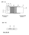
- FIG. 1A is a schematic front view showing a state before winding of the wound electrode body according to Examples 1 and 2 and Comparative Example 2
- FIG. 1B is a direction in which the positive electrode tab and the negative electrode tab protrude similarly.
- It is a model top view at the time of seeing from.
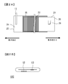
- 2A is a schematic front view showing a state before winding of the wound electrode body according to Comparative Example 1
- FIG. 2B is a schematic plan view when the wound electrode body is viewed from the protruding direction of the positive electrode tab and the negative electrode tab.
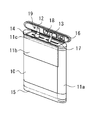
- FIG. It is a perspective view which shows the connection condition of the flat winding electrode body which concerns on Example 1 and 2, and a sealing board.
- FIG. 1A for the wound electrode bodies 10A, 10B, and 10D of the wound electrode bodies according to Examples 1 and 2 and Comparative Example 2, the positive electrode plate 20 and the negative electrode plate 23 are connected via a separator (not shown).
- FIG. 1B is a schematic plan view of the wound electrode bodies 10A, 10B, and 10D when viewed from the direction in which the positive electrode tab 12 and the negative electrode tab 13 protrude. is there.
- FIG. 2A is a schematic front view showing a state before winding in which the positive electrode plate 20 and the negative electrode plate 23 are overlapped via a separator (not shown) in the wound electrode body 10C of Comparative Example 1.
- FIG. 2B is a schematic plan view when the wound electrode body 10C is viewed from the direction in which the positive electrode tab 12 and the negative electrode tab 13 protrude.
- FIG. 3 is a perspective view illustrating a connection state between the flat spirally wound electrode body 10 ⁇ / b> A of Example 1 and the sealing plate 16.
- 4 is a perspective view showing a connection state between the flat spirally wound electrode body 10C of Comparative Example 1 and the sealing plate 16.
- FIG. FIG. 5 is a perspective view showing a connection state between the flat spirally wound electrode body 10 ⁇ / b> D and the sealing plate 16 of the second comparative example. In FIG. 1A and FIG. 2A, the separator is not shown.
- the positive electrode plate of each example and comparative example was produced as follows. First, lithium cobaltate as a positive electrode active material, acetylene black as a carbon-based conductive agent, and PVDF (polyvinylidene fluoride) are mixed at a mass ratio of 95: 2.5: 2.5 to obtain NMP (N- Methylpyrrolidone) was kneaded as a solvent to prepare a positive electrode mixture slurry. This slurry was applied to both sides of an aluminum positive electrode core having a thickness of 13 ⁇ m by a doctor blade method and dried to form positive electrode active material layers on both surfaces of the positive electrode core. Then, it compressed using the compression roller and produced the positive electrode plate whose short side length is 43 mm.
- NMP N- Methylpyrrolidone
- the positive electrode plate 20 has a positive electrode at a certain distance from the end at both ends of the long side.
- the aluminum positive electrode tab 12 was ultrasonically welded to the positive electrode core exposed part 21 on the winding start end side. Thereafter, an insulating tape 11c was applied so as to cover both surfaces of the positive electrode tab except for the tip of the positive electrode tab.
- the positive electrode core body exposed portion 21 having no positive electrode active material layer 22 was provided only on the winding end side of the positive electrode plate 20.
- the positive electrode tab 12 was welded to the cut portion 26 formed by making a U-shaped cut in the positive electrode core exposed portion 21, but as described later, the state of the electrode body until the formation of the cut portion 26 was reached. Winding was performed, and welding of the positive electrode tab to the cut portion 26 was performed after winding.
- the size of the aluminum piece as the positive electrode tab 12 is 0.03 mm thickness ⁇ 6 mm width ⁇ 25 mm length in the wound electrode bodies 10A, 10B and 10C of Examples 1 and 2 and Comparative Example 1.
- the thickness was 0.1 mm ⁇ width 3 mm ⁇ length 25 mm.
- the negative electrode plate common to Examples 1 and 2 and Comparative Examples 1 and 2 was produced as follows. That is, knead
- CMC carboxymethylcellulose
- SBR styrene butadiene rubber
- the negative electrode core plate 22 has a negative electrode core exposed portion 24 that does not have the negative electrode active material layer 25 on both surfaces of the negative electrode core by a certain distance from the winding start end of the negative electrode core.
- the nickel negative electrode tab 13 was ultrasonically welded to the negative electrode core exposed portion 24.
- the nickel piece as the negative electrode tab 13 used the thing of thickness 0.1mm * width 3mm * length 25mm.
- Non-aqueous electrolyte As a non-aqueous electrolyte, LiPF 6 is used as a solute in a non-aqueous solvent mixed so that the volume mixing ratio of ethylene carbonate, ethyl methyl carbonate and diethyl carbonate is 40:30:30 so that the concentration becomes 1 mol / L. Used by dissolving.
- the positive electrode plate 20 and the negative electrode plate 23 produced as described above are connected to the side on which the positive electrode tab 12 is welded and the negative electrode tab 13 as shown in FIG. 1A.
- the positive electrode tab 12 is made of the negative electrode tab 13 and the negative electrode active material layer 25 so that the side on which the positive electrode tab 12 and the negative electrode tab 13 are disposed is reduced.
- the positive electrode plate 20 and the negative electrode plate 23 are arranged such that the negative electrode core exposed portion 24 is on the winding start side, and the positive electrode core exposed portion 21. Is wound on the side with the separator made of a polyethylene microporous film sandwiched between the ends, fixed by the insulating tape 11a, and flattened by crushing, The positive electrode tab 12 was welded in a state where the cut portion 26 was folded at a right angle, and the cut portion 26 was further folded, whereby a flat wound electrode body 10B was produced.
- the insulating spacers 14 and 15 and the insulating tape 11b are attached to the flat spirally wound electrode bodies 10A to 10D manufactured as described above, and the positive electrode tab 12 and the negative electrode tab 13 are bent into predetermined shapes, respectively.
- the wound electrode bodies 10A to 10D are inserted into a rectangular metal battery outer body (not shown) whose one end surface in the longitudinal direction is open and whose peripheral surface is closed, and the opening of the battery outer body is sealed with a sealing plate 16 and sealing the electrolyte injection hole 19 after injecting a predetermined amount of the non-aqueous electrolyte from the electrolyte injection hole 19, thereby producing the nonaqueous electrolyte secondary batteries of the respective examples and comparative examples.
- a sealing plate 16 and sealing the electrolyte injection hole 19 after injecting a predetermined amount of the non-aqueous electrolyte from the electrolyte injection hole 19, thereby producing the nonaqueous electrolyte secondary batteries of the respective examples and comparative examples.
- FIG. 3 schematically shows the connection state between the flat wound electrode bodies 10A and 10B and the sealing plate 16 in Examples 1 and 2, and the connection between the flat spiral electrode body 10C and the sealing plate 16 in Comparative Example 1 is shown. The situation is schematically shown in FIG.
- the tip of the negative electrode tab 13 is laser-welded to the negative electrode terminal 18, and the positive electrode tab 12 with the insulating tape 11c attached on both sides is bent and molded.
- the dimension of the nonaqueous electrolyte secondary battery common to each obtained Example and comparative example is thickness 5.2mm x width 34mm x height 50mm, and design capacity is 1150mAh.
- the prepared battery was charged under the same conditions as described above, and one end of each lead wire was connected to the battery surface side of the negative electrode terminal 18 and the sealing plate 16 (positive electrode). In order to eliminate the influence of the magnetic field due to the current flowing in the lead wires, the lead wires were twisted together. Then, the other end of the lead wire was connected to the output terminal of the power supply, and the magnetic field around the battery was measured while applying a discharge load having a pulse waveform of GSM specifications to the battery using the power supply.
- the pulse waveform shape of the GSM specification is that the frequency is 217 Hz, the current 2A is 0.6 milliseconds, and 0.1 A is 1.4 milliseconds.
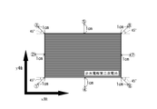
- the side where the area of the battery is the maximum is left in the vertical direction, and the plane is 1 cm above the side of the battery.
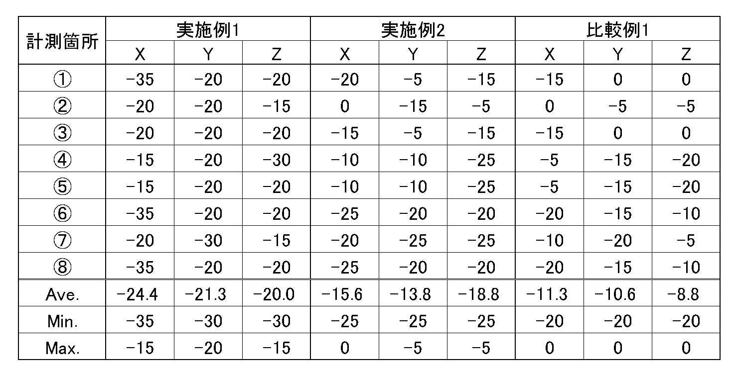
- the magnitude of the magnetic field was obtained at 8 locations shown in FIG. The results are shown in Table 1.
- FIG. 6 is a schematic plan view in plan view of a state in which the side surface having the largest battery area is placed in an up-down direction, and the side provided with the sealing plate 16 is arranged on the left side,
- the height direction of the battery was defined as the x axis, the width direction as the y axis, and the thickness direction as the z axis (not shown).
- Table 1 also shows the magnetic field strength (unit: xyz) in the xyz directions with respect to the strength of the magnetic field at the eight locations shown in FIG. 6 (however, located on a plane 1 cm away from the battery surface in the z-axis direction).
- dB ⁇ A / m the magnetic field strength in the x-axis direction of Comparative Example 1 at the position of the circled numeral 2 was used as a reference (0 dB ⁇ A / m).
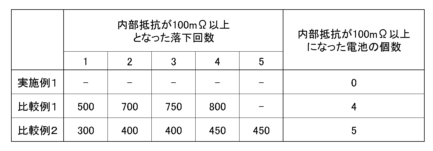
- Drop reliability test A drop reliability test was performed as follows. That is, five nonaqueous electrolyte secondary batteries of Examples 1 and 2 and Comparative Example 2 were prepared, and a severe drop test was performed 1000 times in a random direction on a steel plate from a height of 1 m, and the internal resistance was 100 m ⁇ . The number of batteries that became above was counted. The internal resistance was measured every 50 drops, and when the internal resistance was 100 m ⁇ or more, the test was terminated at that time and the number of drops at which the internal resistance was 100 m ⁇ or more was recorded. The results are shown in Table 2.
- the positions of the positive electrode tab 12 and the negative electrode tab 13 are both arranged on the winding start side of the wound electrode body. For this reason, the current flowing through the positive electrode plate 20 and the current flowing through the negative electrode plate 23 are in opposite directions, and the magnetic fields generated by the respective currents cancel each other, so that the magnetic field leaking to the outside is suppressed.
- Comparative Example 1 since the positive electrode tab 12 is positioned so as to be on the winding end side and the negative electrode tab 13 is on the winding start side, the magnetic field generated by the current flowing through the positive electrode plate 20 and the negative electrode plate 23 flow. The magnetic field generated by the electric current is added without being canceled out, and becomes a magnetic field leaking to the outside.
- Example 2 the strength of the magnetic field stronger than ⁇ 10 dB ⁇ A / m is confirmed in the measurement points of the circled number 1, the circled number 2 and the circled number 3, whereas in Example 1, either Is a magnetic field strength of less than ⁇ 10 dB ⁇ A / m. It is assumed that the difference in magnetic field strength between the circled number 1, the circled number 2 and the circled number 3 is mainly caused by the difference in the current flowing through the tab. It can be seen that the shorter the distance between, the greater the effect of reducing the magnetic field.
- the distance between the positive electrode tab 12 and the negative electrode tab 13 is preferably 2 mm or more.
- Example 2 where the distance between the positive electrode tab 12 and the negative electrode tab 13 is 12 mm, the effect of reducing the magnetic field is exhibited. Is preferably 10 mm or less, because the magnetic field strength at each measurement point can be made smaller than ⁇ 10 dB ⁇ A / m in each of the x, y, and z directions.
- Comparative Example 2 when each battery after the drop test was disassembled and the internal state was visually confirmed, in Comparative Example 2, the positive electrode tab 12 was partially broken or completely broken for the battery having an internal resistance of 100 m ⁇ or more. In Comparative Example 1, the positive electrode tab 12 was completely broken in all the batteries. On the other hand, in Example 1, no breakage was observed in the positive electrode tab 12 for any of the batteries.
- Example 1 has sufficient drop reliability and that Comparative Example 1 and Comparative Example 2 have higher drop reliability.
- the reason for the above drop reliability is estimated as follows. That is, the thickness of the positive electrode tab 12 is 0.1 mm in the comparative example 2, whereas the thickness of the positive electrode tab 12 is 0.03 mm in the comparative example 1, so that the impact at the time of dropping is transmitted to the positive electrode tab 12.
- the tip of the positive electrode tab 12 is connected to the sealing plate 16.
- Comparative Example 1 has improved drop reliability compared to Comparative Example 2.
- the positive electrode tab 12 bend gently, and it is preferable that the thickness of the positive electrode tab 12 be 70 ⁇ m or less from another examination result.
- Example 1 since both sides of the bent portion base are covered with the insulating tape and the positive electrode tab 12 is arranged on the winding start side, the length of the bent portion is shorter than that of Comparative Example 1, It is presumed that the drop reliability is synergistically improved by reducing the load applied to the bent portion at the time of the drop impact.
- 10A to 10D Flat wound electrode body 11a to 11c ... Insulating tape 12 ... Positive electrode tab 13 ... Negative electrode tab 14, 15 ... Insulating spacer 16 ... Sealing plate 17 ... Slit 18 ... Negative electrode terminal 19 ... Electrolyte injection hole 20 ... Positive Electrode plate 21 ... Positive electrode core exposed portion 22 ... Positive electrode active material layer 23 ... Negative electrode plate 24 ; Negative electrode core exposed portion 25 ... Negative electrode active material layer
Landscapes
- Chemical & Material Sciences (AREA)
- Chemical Kinetics & Catalysis (AREA)
- Electrochemistry (AREA)
- General Chemical & Material Sciences (AREA)
- Engineering & Computer Science (AREA)
- Manufacturing & Machinery (AREA)
- Connection Of Batteries Or Terminals (AREA)
- Secondary Cells (AREA)
Abstract
Description
各実施例及び比較例の正極極板は以下のようにして作製した。まず、正極活物質としてコバルト酸リチウムと、炭素系導電剤であるアセチレンブラックと、PVDF(ポリフッ化ビニリデン)を、95:2.5:2.5の質量比で混合して、NMP(N-メチルピロリドン)を溶剤として混練し、正極合剤スラリーを調製した。このスラリーを厚さ13μmのアルミニウム製の正極芯体の両面にドクターブレード法により塗布、乾燥して、正極芯体の両面に正極活物質層を形成した。その後、圧縮ローラーを用いて圧縮し、短辺の長さが43mmの正極極板を作製した。
そして、実施例1、2及び比較例2の巻回電極体10A、10B及び10Dにおいては、図1Aに示すように、正極極板20に、長辺の両端において端部から一定の距離だけ正極芯体の両面ともに正極活物質層22を有しない正極芯体露出部21を設けた後、巻回始端側の正極芯体露出部21に、アルミニウム製の正極タブ12を超音波溶接した。その後、正極タブの先端部をのぞき正極タブの両面を覆うように絶縁テープを11cを貼付した。
実施例1、2、比較例1及び2に共通する負極極板は、以下のようにして作製した。すなわち、人造黒鉛と、カルボキシメチルセルロース(CMC)を純水に1質量%溶解させたものと、スチレンブタジエンゴム(SBR)とを固形分比で98:1:1の質量比となるように、混練して負極合剤スラリーを作製した。次いで、厚さ8μmの銅製の負極芯体の両面にドクターブレード法により塗布後、乾燥して負極芯体の両面に負極活物質層25を形成した。この後、圧縮ローラーを用いて圧縮し、短辺の長さが44mmの負極極板23を作製した。
負極極板22には、図1A及び図2Aに示したように、負極芯体の巻回始端から一定の距離だけ負極芯体の両面ともに負極活物質層25を有しない負極芯体露出部24を設けておき、この負極芯体露出部24に、ニッケル製の負極タブ13を超音波溶接した。なお、負極タブ13としてのニッケル片は、厚み0.1mm×幅3mm×長さ25mmのものを用いた。
非水電解質としては、エチレンカーボネート、エチルメチルカーボネート及びジエチルカーボネートの体積混合比が40:30:30となるように混合した非水溶媒に、LiPF6を溶質として1mol/Lの濃度になるように溶解して用いた。
実施例1、2及び比較例2においては、上述のようにして作製した正極極板20と負極極板23とを、図1Aに示すように正極タブ12が溶接されている側及び負極タブ13が溶接されている側が共に巻き始め側となるようにすると共に、正極タブ12及び負極タブ13の配置部分の凹凸が少なくなるようにするため、正極タブ12が負極タブ13と負極活物質層25との間に位置するように、また、負極タブ13が正極芯体露出部21とは重ならない位置になるようにして、ポリエチレン製微多孔膜からなるセパレータを挟んで重ね、正極極板20及び負極極板23が互いに絶縁された状態で巻回し、巻き終わり端部を絶縁テープ11a(図3及び図4参照)によって固定し、押し潰すことによって実施例1の偏平状巻回電極体10A、実施例2の偏平状巻回電極体10B及び比較例2の偏平状巻回電極体10Dを作製した。なお、電池の横幅方向における、正極タブ12と負極タブ13との間の距離Lは、実施例1及び比較例2においてはL=4mmとしたのに対し、実施例2においてはL=12mmとなるようにした。
次いで、上述のようにして作製された偏平状巻回電極体10A~10Dに絶縁スペーサ14、15及び絶縁テープ11bを取り付け、正極タブ12及び負極タブ13をそれぞれ所定形状に曲げた後、偏平状巻回電極体10A~10Dを、長手方向の一端面が開口し、周囲面が閉鎖した角形の金属製の電池外装体(図示省略)内に挿入して、電池外装体の開口部を封口板16で封口し、電解液注入孔19からの所定量の非水電解液の注入後電解液注入孔19を封止することにより、各実施例及び比較例の非水電解質二次電池を作製したが、以下において、それぞれの偏平状巻回電極体10A~10Dと封口板16との接続状況、及び、電池外装体と封口板16との封止方法の違いについて説明する。
このようにして作製された非水電解質二次電池の内、実施例1、2及び比較例1については、以下のようにして、放電により生じる磁界を計測した。はじめに、1It=1150mAの定電流で電池電圧が4.2Vになるまで充電し、電池電圧が4、2Vに達した後は4.2Vの定電圧で充電電流が23mAになるまで充電して満充電状態とした。次いで、1It=1150mAの定電流で放電して電池の状態を整えた。
以下のようにして、落下信頼性試験を行った。すなわち、実施例1、2及び比較例2の非水電解質二次電池を各5個ずつ用意し、1mの高さから鉄板上にランダム方向に1000回落とす過酷落下試験を行い、内部抵抗が100mΩ以上となった電池の個数をカウントした。なお、内部抵抗については、落下50回ごとに測定し、内部抵抗が100mΩ以上となった場合はその時点で試験を終了すると共に、内部抵抗が100mΩ以上となった落下回数を記録した。結果を表2に示す。
Claims (3)
- 正極活物質層及び正極芯体露出部を有する正極極板と、負極活物質層及び負極芯体露出部を有する負極極板とが、セパレータを介して巻回された偏平形状の巻回電極体と
一端に開口部を有し、前記巻回電極体が収納される偏平形状の金属製の外装体と、
前記金属製の外装体の前記開口部に嵌合される封口板と、
前記正極芯体露出部に電気的に接合された正極タブと、前記負極芯体露出部に電気的に接合された負極タブと、を備える非水電解質二次電池において、
前記正極タブが電気的に接合された前記正極芯体露出部、及び、前記負極タブが電気的に接合された前記負極芯体露出部は、共に前記巻回電極体の巻き始め側に配置され、
前記正極タブは、前記外装体と前記封口板との嵌合部で挟まれた状態で前記外装体及び前記封口板に溶接され、
前記負極タブは、前記封口板に備えられた負極端子に電気的に接合され、
前記正極タブと前記負極タブとが、電池の幅方向において、2mm以上12mm以下の間隔で離間している、ことを特徴とする非水電解質二次電池。 - 前記正極タブは、アルミニウム製又はアルミニウム合金製であり、かつ、厚みが前記正極芯体の厚み以上、70μm以下であることを特徴とする請求項1に記載の非水電解質二次電池。
- 前記正極タブは、両面が絶縁テープで覆われていることを特徴とする請求項1または2に記載の非水電解質二次電池。
Priority Applications (2)
| Application Number | Priority Date | Filing Date | Title |
|---|---|---|---|
| US13/993,965 US9935339B2 (en) | 2010-12-28 | 2011-12-16 | Nonaqueous electrolyte secondary battery |
| JP2012550826A JP6173692B2 (ja) | 2010-12-28 | 2011-12-16 | 非水電解質二次電池 |
Applications Claiming Priority (2)
| Application Number | Priority Date | Filing Date | Title |
|---|---|---|---|
| JP2010294253 | 2010-12-28 | ||
| JP2010-294253 | 2010-12-28 |
Publications (1)
| Publication Number | Publication Date |
|---|---|
| WO2012090726A1 true WO2012090726A1 (ja) | 2012-07-05 |
Family
ID=46382839
Family Applications (1)
| Application Number | Title | Priority Date | Filing Date |
|---|---|---|---|
| PCT/JP2011/079161 Ceased WO2012090726A1 (ja) | 2010-12-28 | 2011-12-16 | 非水電解質二次電池 |
Country Status (3)
| Country | Link |
|---|---|
| US (1) | US9935339B2 (ja) |
| JP (1) | JP6173692B2 (ja) |
| WO (1) | WO2012090726A1 (ja) |
Cited By (8)
| Publication number | Priority date | Publication date | Assignee | Title |
|---|---|---|---|---|
| CN103825056A (zh) * | 2014-03-24 | 2014-05-28 | 四川剑兴锂电池有限公司 | 一种锂电池卷芯的卷绕方法 |
| JP5931756B2 (ja) * | 2011-02-08 | 2016-06-08 | 三洋電機株式会社 | パック電池 |
| WO2017043178A1 (ja) * | 2015-09-09 | 2017-03-16 | ソニー株式会社 | 二次電池 |
| WO2018100853A1 (ja) * | 2016-11-30 | 2018-06-07 | パナソニックIpマネジメント株式会社 | 円筒形電池 |
| CN109417152A (zh) * | 2016-06-28 | 2019-03-01 | 宁德新能源科技有限公司 | 二次电池电芯 |
| JP2021146198A (ja) * | 2020-03-17 | 2021-09-27 | ソニー・オリンパスメディカルソリューションズ株式会社 | 医療用画像処理装置及び医療用観察システム |
| JP2022553025A (ja) * | 2019-10-28 | 2022-12-21 | エルジー エナジー ソリューション リミテッド | 電極組立体およびそれを含む二次電池 |
| US12089802B2 (en) | 2020-03-17 | 2024-09-17 | Sony Olympus Medical Solutions Inc. | Medical image processing apparatus and medical observation system |
Families Citing this family (13)
| Publication number | Priority date | Publication date | Assignee | Title |
|---|---|---|---|---|
| CN203733894U (zh) | 2014-01-17 | 2014-07-23 | 宁德新能源科技有限公司 | 锂离子电池 |
| KR102198797B1 (ko) * | 2014-02-10 | 2021-01-05 | 삼성에스디아이 주식회사 | 이차전지 팩 |
| KR102234292B1 (ko) * | 2014-04-09 | 2021-03-31 | 삼성에스디아이 주식회사 | 전극 조립체 및 이를 구비한 이차 전지 |
| WO2017035749A1 (zh) | 2015-08-31 | 2017-03-09 | 宁德新能源科技有限公司 | 二次电池电芯及其卷绕成型系统 |
| CN107293805B (zh) * | 2016-03-31 | 2023-02-28 | 宁德新能源科技有限公司 | 卷绕式电芯及卷针 |
| US20190148781A1 (en) * | 2017-11-14 | 2019-05-16 | Bae Systems Information And Electronic Systems Integration Inc. | Battery with suppressed magnetic field |
| CN216213939U (zh) | 2021-11-01 | 2022-04-05 | 宁德新能源科技有限公司 | 一种电芯、电池及电子设备 |
| CN114373885B (zh) * | 2021-12-31 | 2023-09-15 | 东莞新能源科技有限公司 | 电化学装置及用电设备 |
| CN117480653A (zh) * | 2023-05-29 | 2024-01-30 | 宁德新能源科技有限公司 | 一种电化学装置和电子装置 |
| CN116598601A (zh) * | 2023-07-10 | 2023-08-15 | 宁德新能源科技有限公司 | 电芯及用电设备 |
| CN116646616B (zh) * | 2023-07-26 | 2024-03-12 | 宁德新能源科技有限公司 | 二次电池和用电设备 |
| CN222463345U (zh) * | 2024-03-11 | 2025-02-11 | 欣旺达动力科技股份有限公司 | 单体电池以及电池包 |
| DE212025000072U1 (de) * | 2025-01-07 | 2026-04-23 | Contemporary Amperex Technology Co., Limited | Batteriezelle, Batterievorrichtung und stromverbrauchende Vorrichtung |
Citations (6)
| Publication number | Priority date | Publication date | Assignee | Title |
|---|---|---|---|---|
| JP2003086166A (ja) * | 2001-09-14 | 2003-03-20 | Hitachi Maxell Ltd | 非水電解質二次電池 |
| JP2003272597A (ja) * | 2002-03-15 | 2003-09-26 | Sanyo Electric Co Ltd | 密閉型電池 |
| JP2004253381A (ja) * | 2003-02-19 | 2004-09-09 | Samsung Sdi Co Ltd | ジェリーロール型の電池部と、このワインディング方法及びこれを具備したリチウム二次電池 |
| JP2005209530A (ja) * | 2004-01-23 | 2005-08-04 | Toshiba Corp | 非水電解質二次電池 |
| JP2006012808A (ja) * | 2004-06-22 | 2006-01-12 | Samsung Sdi Co Ltd | 電極組立体及びこれを用いるリチウムイオン二次電池 |
| WO2010070805A1 (ja) * | 2008-12-15 | 2010-06-24 | パナソニック株式会社 | 電池 |
Family Cites Families (7)
| Publication number | Priority date | Publication date | Assignee | Title |
|---|---|---|---|---|
| JP3643661B2 (ja) * | 1996-11-29 | 2005-04-27 | 三洋電機株式会社 | 密閉型電池の製造方法 |
| JP3509059B2 (ja) | 1999-03-31 | 2004-03-22 | Necトーキン栃木株式会社 | 巻回型電池およびその製造方法 |
| JP4097443B2 (ja) * | 2002-03-27 | 2008-06-11 | 三洋電機株式会社 | リチウム二次電池 |
| KR100846579B1 (ko) * | 2002-07-13 | 2008-07-16 | 삼성에스디아이 주식회사 | 리튬 이온 전지의 극판 조립체 및 이를 이용한 리튬 이온전지 |
| KR100646535B1 (ko) * | 2005-03-23 | 2006-11-23 | 삼성에스디아이 주식회사 | 리튬 이온 전지용 전극조립체와 이를 이용한 리튬 이온이차전지 |
| JP4863636B2 (ja) * | 2005-03-29 | 2012-01-25 | 三洋電機株式会社 | 渦巻式電極の角型電池 |
| JP5676620B2 (ja) * | 2010-08-23 | 2015-02-25 | エルジー・ケム・リミテッド | 改良構造のゼリーロールおよびそれを含む二次電池 |
-
2011
- 2011-12-16 JP JP2012550826A patent/JP6173692B2/ja active Active
- 2011-12-16 WO PCT/JP2011/079161 patent/WO2012090726A1/ja not_active Ceased
- 2011-12-16 US US13/993,965 patent/US9935339B2/en active Active
Patent Citations (6)
| Publication number | Priority date | Publication date | Assignee | Title |
|---|---|---|---|---|
| JP2003086166A (ja) * | 2001-09-14 | 2003-03-20 | Hitachi Maxell Ltd | 非水電解質二次電池 |
| JP2003272597A (ja) * | 2002-03-15 | 2003-09-26 | Sanyo Electric Co Ltd | 密閉型電池 |
| JP2004253381A (ja) * | 2003-02-19 | 2004-09-09 | Samsung Sdi Co Ltd | ジェリーロール型の電池部と、このワインディング方法及びこれを具備したリチウム二次電池 |
| JP2005209530A (ja) * | 2004-01-23 | 2005-08-04 | Toshiba Corp | 非水電解質二次電池 |
| JP2006012808A (ja) * | 2004-06-22 | 2006-01-12 | Samsung Sdi Co Ltd | 電極組立体及びこれを用いるリチウムイオン二次電池 |
| WO2010070805A1 (ja) * | 2008-12-15 | 2010-06-24 | パナソニック株式会社 | 電池 |
Cited By (10)
| Publication number | Priority date | Publication date | Assignee | Title |
|---|---|---|---|---|
| JP5931756B2 (ja) * | 2011-02-08 | 2016-06-08 | 三洋電機株式会社 | パック電池 |
| CN103825056A (zh) * | 2014-03-24 | 2014-05-28 | 四川剑兴锂电池有限公司 | 一种锂电池卷芯的卷绕方法 |
| WO2017043178A1 (ja) * | 2015-09-09 | 2017-03-16 | ソニー株式会社 | 二次電池 |
| US10658650B2 (en) | 2015-09-09 | 2020-05-19 | Murata Manufacturing Co., Ltd. | Secondary battery |
| CN109417152A (zh) * | 2016-06-28 | 2019-03-01 | 宁德新能源科技有限公司 | 二次电池电芯 |
| WO2018100853A1 (ja) * | 2016-11-30 | 2018-06-07 | パナソニックIpマネジメント株式会社 | 円筒形電池 |
| JP2022553025A (ja) * | 2019-10-28 | 2022-12-21 | エルジー エナジー ソリューション リミテッド | 電極組立体およびそれを含む二次電池 |
| JP7387977B2 (ja) | 2019-10-28 | 2023-11-29 | エルジー エナジー ソリューション リミテッド | 電極組立体およびそれを含む二次電池 |
| JP2021146198A (ja) * | 2020-03-17 | 2021-09-27 | ソニー・オリンパスメディカルソリューションズ株式会社 | 医療用画像処理装置及び医療用観察システム |
| US12089802B2 (en) | 2020-03-17 | 2024-09-17 | Sony Olympus Medical Solutions Inc. | Medical image processing apparatus and medical observation system |
Also Published As
| Publication number | Publication date |
|---|---|
| US20130260203A1 (en) | 2013-10-03 |
| US9935339B2 (en) | 2018-04-03 |
| JP6173692B2 (ja) | 2017-08-02 |
| JPWO2012090726A1 (ja) | 2014-06-05 |
Similar Documents
| Publication | Publication Date | Title |
|---|---|---|
| JP6173692B2 (ja) | 非水電解質二次電池 | |
| CN103370815B (zh) | 电池及电池的制造方法 | |
| CN107710459B (zh) | 电池及电池包 | |
| US9142854B2 (en) | Battery having enhanced electrical insulation capability | |
| JP6058400B2 (ja) | 非水電解液二次電池 | |
| JP2015035250A (ja) | 非水電解質二次電池 | |
| CN105917512A (zh) | 二次电池和二次电池的制造方法 | |
| CN112204791A (zh) | 电池及电池包 | |
| JP2007265846A (ja) | 円筒形電池およびその製造方法 | |
| WO2012053556A1 (ja) | 非水電解質二次電池 | |
| JP2013171784A (ja) | 角形非水電解質二次電池 | |
| JP2013097903A (ja) | 非水電解液二次電池 | |
| WO2018100853A1 (ja) | 円筒形電池 | |
| WO2012053557A1 (ja) | 非水電解質二次電池 | |
| JP5294641B2 (ja) | 密閉電池 | |
| CN111183542A (zh) | 非水电解质二次电池 | |
| JP5337418B2 (ja) | 非水電解液二次電池 | |
| JP2015115261A (ja) | 密閉型電池 | |
| JP2011222128A (ja) | 二次電池 | |
| JP5270910B2 (ja) | 蓄電池用正極集電体とタブの超音波溶接法 | |
| JP5222030B2 (ja) | 捲回式二次電池およびその製造方法 | |
| WO2017051516A1 (ja) | 非水電解質二次電池 | |
| JP2018139187A (ja) | 捲回型電池 | |
| CN104285319B (zh) | 锂二次电池用负极及包含该负极的锂离子二次电池 | |
| KR20160120502A (ko) | 전극조립체 수납 공간을 최대화하여 용량 증대를 구현한 이차전지 및 이를 제조하는 방법 |
Legal Events
| Date | Code | Title | Description |
|---|---|---|---|
| 121 | Ep: the epo has been informed by wipo that ep was designated in this application |
Ref document number: 11853323 Country of ref document: EP Kind code of ref document: A1 |
|
| ENP | Entry into the national phase |
Ref document number: 2012550826 Country of ref document: JP Kind code of ref document: A |
|
| WWE | Wipo information: entry into national phase |
Ref document number: 13993965 Country of ref document: US |
|
| NENP | Non-entry into the national phase |
Ref country code: DE |
|
| 122 | Ep: pct application non-entry in european phase |
Ref document number: 11853323 Country of ref document: EP Kind code of ref document: A1 |