WO2012086814A1 - Structure en nid d'abeilles - Google Patents
Structure en nid d'abeilles Download PDFInfo
- Publication number
- WO2012086814A1 WO2012086814A1 PCT/JP2011/079936 JP2011079936W WO2012086814A1 WO 2012086814 A1 WO2012086814 A1 WO 2012086814A1 JP 2011079936 W JP2011079936 W JP 2011079936W WO 2012086814 A1 WO2012086814 A1 WO 2012086814A1
- Authority
- WO
- WIPO (PCT)
- Prior art keywords
- honeycomb structure
- electrode
- silicon carbide
- outer peripheral
- pair
- Prior art date
Links
- 238000005192 partition Methods 0.000 claims abstract description 27
- 230000002093 peripheral effect Effects 0.000 claims description 100
- 239000004020 conductor Substances 0.000 claims description 22
- 239000012530 fluid Substances 0.000 claims description 4
- 230000035939 shock Effects 0.000 abstract description 34
- 239000003054 catalyst Substances 0.000 abstract description 32
- HBMJWWWQQXIZIP-UHFFFAOYSA-N silicon carbide Chemical compound [Si+]#[C-] HBMJWWWQQXIZIP-UHFFFAOYSA-N 0.000 description 120
- XUIMIQQOPSSXEZ-UHFFFAOYSA-N Silicon Chemical compound [Si] XUIMIQQOPSSXEZ-UHFFFAOYSA-N 0.000 description 105
- 239000002245 particle Substances 0.000 description 89
- 229910010271 silicon carbide Inorganic materials 0.000 description 82
- 229910052751 metal Inorganic materials 0.000 description 80
- 239000002184 metal Substances 0.000 description 80
- 239000010703 silicon Substances 0.000 description 72
- 229910052710 silicon Inorganic materials 0.000 description 72
- 239000002994 raw material Substances 0.000 description 62
- 239000011148 porous material Substances 0.000 description 48
- 239000007789 gas Substances 0.000 description 40
- 238000012360 testing method Methods 0.000 description 36
- 238000000034 method Methods 0.000 description 32
- 239000011863 silicon-based powder Substances 0.000 description 30
- 239000000463 material Substances 0.000 description 28
- 239000000843 powder Substances 0.000 description 24
- 239000011230 binding agent Substances 0.000 description 20
- XLYOFNOQVPJJNP-UHFFFAOYSA-N water Substances O XLYOFNOQVPJJNP-UHFFFAOYSA-N 0.000 description 20
- 238000010438 heat treatment Methods 0.000 description 18
- ATUOYWHBWRKTHZ-UHFFFAOYSA-N Propane Chemical compound CCC ATUOYWHBWRKTHZ-UHFFFAOYSA-N 0.000 description 16
- 238000010304 firing Methods 0.000 description 16
- 238000001035 drying Methods 0.000 description 15
- 238000011156 evaluation Methods 0.000 description 15
- 239000000758 substrate Substances 0.000 description 15
- 239000004094 surface-active agent Substances 0.000 description 13
- 238000007561 laser diffraction method Methods 0.000 description 12
- 230000000694 effects Effects 0.000 description 11
- LYCAIKOWRPUZTN-UHFFFAOYSA-N Ethylene glycol Chemical compound OCCO LYCAIKOWRPUZTN-UHFFFAOYSA-N 0.000 description 9
- 238000010586 diagram Methods 0.000 description 9
- 238000004898 kneading Methods 0.000 description 9
- 238000004519 manufacturing process Methods 0.000 description 9
- 238000009826 distribution Methods 0.000 description 8
- QSHDDOUJBYECFT-UHFFFAOYSA-N mercury Chemical compound [Hg] QSHDDOUJBYECFT-UHFFFAOYSA-N 0.000 description 8
- 229910052753 mercury Inorganic materials 0.000 description 8
- 230000003287 optical effect Effects 0.000 description 8
- 239000001294 propane Substances 0.000 description 8
- 239000004927 clay Substances 0.000 description 7
- 239000002131 composite material Substances 0.000 description 7
- 239000011347 resin Substances 0.000 description 7
- 229920005989 resin Polymers 0.000 description 7
- SBEQWOXEGHQIMW-UHFFFAOYSA-N silicon Chemical compound [Si].[Si] SBEQWOXEGHQIMW-UHFFFAOYSA-N 0.000 description 7
- 230000035882 stress Effects 0.000 description 7
- 229920002678 cellulose Polymers 0.000 description 6
- 239000001913 cellulose Substances 0.000 description 6
- 235000010980 cellulose Nutrition 0.000 description 6
- 238000001816 cooling Methods 0.000 description 6
- 239000010419 fine particle Substances 0.000 description 6
- -1 hydroxypropoxyl Chemical group 0.000 description 6
- 239000001866 hydroxypropyl methyl cellulose Substances 0.000 description 6
- 229920003088 hydroxypropyl methyl cellulose Polymers 0.000 description 6
- 235000010979 hydroxypropyl methyl cellulose Nutrition 0.000 description 6
- UFVKGYZPFZQRLF-UHFFFAOYSA-N hydroxypropyl methyl cellulose Chemical compound OC1C(O)C(OC)OC(CO)C1OC1C(O)C(O)C(OC2C(C(O)C(OC3C(C(O)C(O)C(CO)O3)O)C(CO)O2)O)C(CO)O1 UFVKGYZPFZQRLF-UHFFFAOYSA-N 0.000 description 6
- 238000005259 measurement Methods 0.000 description 6
- 229920000609 methyl cellulose Polymers 0.000 description 6
- 239000001923 methylcellulose Substances 0.000 description 6
- 235000010981 methylcellulose Nutrition 0.000 description 6
- 239000011856 silicon-based particle Substances 0.000 description 6
- 238000011282 treatment Methods 0.000 description 6
- 238000004364 calculation method Methods 0.000 description 5
- 239000000203 mixture Substances 0.000 description 5
- OKTJSMMVPCPJKN-UHFFFAOYSA-N Carbon Chemical compound [C] OKTJSMMVPCPJKN-UHFFFAOYSA-N 0.000 description 4
- PEDCQBHIVMGVHV-UHFFFAOYSA-N Glycerine Chemical compound OCC(O)CO PEDCQBHIVMGVHV-UHFFFAOYSA-N 0.000 description 4
- 239000000654 additive Substances 0.000 description 4
- 230000015572 biosynthetic process Effects 0.000 description 4
- 238000009429 electrical wiring Methods 0.000 description 4
- 238000001125 extrusion Methods 0.000 description 4
- 230000005484 gravity Effects 0.000 description 4
- 230000020169 heat generation Effects 0.000 description 4
- 238000000465 moulding Methods 0.000 description 4
- LNAZSHAWQACDHT-XIYTZBAFSA-N (2r,3r,4s,5r,6s)-4,5-dimethoxy-2-(methoxymethyl)-3-[(2s,3r,4s,5r,6r)-3,4,5-trimethoxy-6-(methoxymethyl)oxan-2-yl]oxy-6-[(2r,3r,4s,5r,6r)-4,5,6-trimethoxy-2-(methoxymethyl)oxan-3-yl]oxyoxane Chemical compound CO[C@@H]1[C@@H](OC)[C@H](OC)[C@@H](COC)O[C@H]1O[C@H]1[C@H](OC)[C@@H](OC)[C@H](O[C@H]2[C@@H]([C@@H](OC)[C@H](OC)O[C@@H]2COC)OC)O[C@@H]1COC LNAZSHAWQACDHT-XIYTZBAFSA-N 0.000 description 3
- 229920002134 Carboxymethyl cellulose Polymers 0.000 description 3
- 239000004375 Dextrin Substances 0.000 description 3
- 229920001353 Dextrin Polymers 0.000 description 3
- 229920000663 Hydroxyethyl cellulose Polymers 0.000 description 3
- 239000004354 Hydroxyethyl cellulose Substances 0.000 description 3
- 239000004372 Polyvinyl alcohol Substances 0.000 description 3
- VYPSYNLAJGMNEJ-UHFFFAOYSA-N Silicium dioxide Chemical compound O=[Si]=O VYPSYNLAJGMNEJ-UHFFFAOYSA-N 0.000 description 3
- 229920002472 Starch Polymers 0.000 description 3
- 230000002745 absorbent Effects 0.000 description 3
- 239000002250 absorbent Substances 0.000 description 3
- 230000000996 additive effect Effects 0.000 description 3
- 239000001768 carboxy methyl cellulose Substances 0.000 description 3
- 235000010948 carboxy methyl cellulose Nutrition 0.000 description 3
- 239000008112 carboxymethyl-cellulose Substances 0.000 description 3
- 238000002485 combustion reaction Methods 0.000 description 3
- 235000019425 dextrin Nutrition 0.000 description 3
- 235000014113 dietary fatty acids Nutrition 0.000 description 3
- 239000000194 fatty acid Substances 0.000 description 3
- 229930195729 fatty acid Natural products 0.000 description 3
- 150000004665 fatty acids Chemical class 0.000 description 3
- 229910002804 graphite Inorganic materials 0.000 description 3
- 239000010439 graphite Substances 0.000 description 3
- 235000019447 hydroxyethyl cellulose Nutrition 0.000 description 3
- 238000002156 mixing Methods 0.000 description 3
- 229920002451 polyvinyl alcohol Polymers 0.000 description 3
- 235000019422 polyvinyl alcohol Nutrition 0.000 description 3
- 238000002360 preparation method Methods 0.000 description 3
- 238000000746 purification Methods 0.000 description 3
- 239000000741 silica gel Substances 0.000 description 3
- 229910002027 silica gel Inorganic materials 0.000 description 3
- 239000000344 soap Substances 0.000 description 3
- 239000008107 starch Substances 0.000 description 3
- 235000019698 starch Nutrition 0.000 description 3
- 150000005846 sugar alcohols Polymers 0.000 description 3
- XKRFYHLGVUSROY-UHFFFAOYSA-N Argon Chemical compound [Ar] XKRFYHLGVUSROY-UHFFFAOYSA-N 0.000 description 2
- IJGRMHOSHXDMSA-UHFFFAOYSA-N Atomic nitrogen Chemical compound N#N IJGRMHOSHXDMSA-UHFFFAOYSA-N 0.000 description 2
- 239000012298 atmosphere Substances 0.000 description 2
- 238000005452 bending Methods 0.000 description 2
- 238000009529 body temperature measurement Methods 0.000 description 2
- 239000000919 ceramic Substances 0.000 description 2
- 239000011248 coating agent Substances 0.000 description 2
- 238000000576 coating method Methods 0.000 description 2
- 230000000052 comparative effect Effects 0.000 description 2
- 238000007604 dielectric heating drying Methods 0.000 description 2
- 235000011187 glycerol Nutrition 0.000 description 2
- 238000007602 hot air drying Methods 0.000 description 2
- 230000002706 hydrostatic effect Effects 0.000 description 2
- 230000003647 oxidation Effects 0.000 description 2
- 238000007254 oxidation reaction Methods 0.000 description 2
- 238000007639 printing Methods 0.000 description 2
- 238000009774 resonance method Methods 0.000 description 2
- 230000008646 thermal stress Effects 0.000 description 2
- BQCADISMDOOEFD-UHFFFAOYSA-N Silver Chemical compound [Ag] BQCADISMDOOEFD-UHFFFAOYSA-N 0.000 description 1
- 229910052786 argon Inorganic materials 0.000 description 1
- 239000012300 argon atmosphere Substances 0.000 description 1
- 238000009924 canning Methods 0.000 description 1
- 229910052799 carbon Inorganic materials 0.000 description 1
- 229910052878 cordierite Inorganic materials 0.000 description 1
- 238000005520 cutting process Methods 0.000 description 1
- 230000007423 decrease Effects 0.000 description 1
- 238000005238 degreasing Methods 0.000 description 1
- 238000013461 design Methods 0.000 description 1
- JSKIRARMQDRGJZ-UHFFFAOYSA-N dimagnesium dioxido-bis[(1-oxido-3-oxo-2,4,6,8,9-pentaoxa-1,3-disila-5,7-dialuminabicyclo[3.3.1]nonan-7-yl)oxy]silane Chemical compound [Mg++].[Mg++].[O-][Si]([O-])(O[Al]1O[Al]2O[Si](=O)O[Si]([O-])(O1)O2)O[Al]1O[Al]2O[Si](=O)O[Si]([O-])(O1)O2 JSKIRARMQDRGJZ-UHFFFAOYSA-N 0.000 description 1
- 239000002270 dispersing agent Substances 0.000 description 1
- 239000003906 humectant Substances 0.000 description 1
- 239000012535 impurity Substances 0.000 description 1
- 238000005304 joining Methods 0.000 description 1
- 229910052757 nitrogen Inorganic materials 0.000 description 1
- 238000006213 oxygenation reaction Methods 0.000 description 1
- 238000012545 processing Methods 0.000 description 1
- 238000007493 shaping process Methods 0.000 description 1
- 239000002210 silicon-based material Substances 0.000 description 1
- 229910052709 silver Inorganic materials 0.000 description 1
- 239000004332 silver Substances 0.000 description 1
- 238000005245 sintering Methods 0.000 description 1
- 239000000126 substance Substances 0.000 description 1
- 230000036962 time dependent Effects 0.000 description 1
- 238000011144 upstream manufacturing Methods 0.000 description 1
Images


Classifications
-
- F—MECHANICAL ENGINEERING; LIGHTING; HEATING; WEAPONS; BLASTING
- F01—MACHINES OR ENGINES IN GENERAL; ENGINE PLANTS IN GENERAL; STEAM ENGINES
- F01N—GAS-FLOW SILENCERS OR EXHAUST APPARATUS FOR MACHINES OR ENGINES IN GENERAL; GAS-FLOW SILENCERS OR EXHAUST APPARATUS FOR INTERNAL COMBUSTION ENGINES
- F01N3/00—Exhaust or silencing apparatus having means for purifying, rendering innocuous, or otherwise treating exhaust
- F01N3/08—Exhaust or silencing apparatus having means for purifying, rendering innocuous, or otherwise treating exhaust for rendering innocuous
- F01N3/10—Exhaust or silencing apparatus having means for purifying, rendering innocuous, or otherwise treating exhaust for rendering innocuous by thermal or catalytic conversion of noxious components of exhaust
- F01N3/18—Exhaust or silencing apparatus having means for purifying, rendering innocuous, or otherwise treating exhaust for rendering innocuous by thermal or catalytic conversion of noxious components of exhaust characterised by methods of operation; Control
- F01N3/20—Exhaust or silencing apparatus having means for purifying, rendering innocuous, or otherwise treating exhaust for rendering innocuous by thermal or catalytic conversion of noxious components of exhaust characterised by methods of operation; Control specially adapted for catalytic conversion ; Methods of operation or control of catalytic converters
- F01N3/2006—Periodically heating or cooling catalytic reactors, e.g. at cold starting or overheating
- F01N3/2013—Periodically heating or cooling catalytic reactors, e.g. at cold starting or overheating using electric or magnetic heating means
- F01N3/2026—Periodically heating or cooling catalytic reactors, e.g. at cold starting or overheating using electric or magnetic heating means directly electrifying the catalyst substrate, i.e. heating the electrically conductive catalyst substrate by joule effect
-
- H—ELECTRICITY
- H05—ELECTRIC TECHNIQUES NOT OTHERWISE PROVIDED FOR
- H05B—ELECTRIC HEATING; ELECTRIC LIGHT SOURCES NOT OTHERWISE PROVIDED FOR; CIRCUIT ARRANGEMENTS FOR ELECTRIC LIGHT SOURCES, IN GENERAL
- H05B3/00—Ohmic-resistance heating
- H05B3/02—Details
- H05B3/03—Electrodes
-
- B—PERFORMING OPERATIONS; TRANSPORTING
- B01—PHYSICAL OR CHEMICAL PROCESSES OR APPARATUS IN GENERAL
- B01J—CHEMICAL OR PHYSICAL PROCESSES, e.g. CATALYSIS OR COLLOID CHEMISTRY; THEIR RELEVANT APPARATUS
- B01J35/00—Catalysts, in general, characterised by their form or physical properties
- B01J35/50—Catalysts, in general, characterised by their form or physical properties characterised by their shape or configuration
- B01J35/56—Foraminous structures having flow-through passages or channels, e.g. grids or three-dimensional monoliths
-
- C—CHEMISTRY; METALLURGY
- C04—CEMENTS; CONCRETE; ARTIFICIAL STONE; CERAMICS; REFRACTORIES
- C04B—LIME, MAGNESIA; SLAG; CEMENTS; COMPOSITIONS THEREOF, e.g. MORTARS, CONCRETE OR LIKE BUILDING MATERIALS; ARTIFICIAL STONE; CERAMICS; REFRACTORIES; TREATMENT OF NATURAL STONE
- C04B35/00—Shaped ceramic products characterised by their composition; Ceramics compositions; Processing powders of inorganic compounds preparatory to the manufacturing of ceramic products
- C04B35/515—Shaped ceramic products characterised by their composition; Ceramics compositions; Processing powders of inorganic compounds preparatory to the manufacturing of ceramic products based on non-oxide ceramics
- C04B35/56—Shaped ceramic products characterised by their composition; Ceramics compositions; Processing powders of inorganic compounds preparatory to the manufacturing of ceramic products based on non-oxide ceramics based on carbides or oxycarbides
- C04B35/565—Shaped ceramic products characterised by their composition; Ceramics compositions; Processing powders of inorganic compounds preparatory to the manufacturing of ceramic products based on non-oxide ceramics based on carbides or oxycarbides based on silicon carbide
-
- C—CHEMISTRY; METALLURGY
- C04—CEMENTS; CONCRETE; ARTIFICIAL STONE; CERAMICS; REFRACTORIES
- C04B—LIME, MAGNESIA; SLAG; CEMENTS; COMPOSITIONS THEREOF, e.g. MORTARS, CONCRETE OR LIKE BUILDING MATERIALS; ARTIFICIAL STONE; CERAMICS; REFRACTORIES; TREATMENT OF NATURAL STONE
- C04B38/00—Porous mortars, concrete, artificial stone or ceramic ware; Preparation thereof
- C04B38/0006—Honeycomb structures
-
- F—MECHANICAL ENGINEERING; LIGHTING; HEATING; WEAPONS; BLASTING
- F01—MACHINES OR ENGINES IN GENERAL; ENGINE PLANTS IN GENERAL; STEAM ENGINES
- F01N—GAS-FLOW SILENCERS OR EXHAUST APPARATUS FOR MACHINES OR ENGINES IN GENERAL; GAS-FLOW SILENCERS OR EXHAUST APPARATUS FOR INTERNAL COMBUSTION ENGINES
- F01N3/00—Exhaust or silencing apparatus having means for purifying, rendering innocuous, or otherwise treating exhaust
- F01N3/08—Exhaust or silencing apparatus having means for purifying, rendering innocuous, or otherwise treating exhaust for rendering innocuous
- F01N3/10—Exhaust or silencing apparatus having means for purifying, rendering innocuous, or otherwise treating exhaust for rendering innocuous by thermal or catalytic conversion of noxious components of exhaust
- F01N3/24—Exhaust or silencing apparatus having means for purifying, rendering innocuous, or otherwise treating exhaust for rendering innocuous by thermal or catalytic conversion of noxious components of exhaust characterised by constructional aspects of converting apparatus
- F01N3/28—Construction of catalytic reactors
- F01N3/2803—Construction of catalytic reactors characterised by structure, by material or by manufacturing of catalyst support
- F01N3/2825—Ceramics
- F01N3/2828—Ceramic multi-channel monoliths, e.g. honeycombs
-
- H—ELECTRICITY
- H05—ELECTRIC TECHNIQUES NOT OTHERWISE PROVIDED FOR
- H05B—ELECTRIC HEATING; ELECTRIC LIGHT SOURCES NOT OTHERWISE PROVIDED FOR; CIRCUIT ARRANGEMENTS FOR ELECTRIC LIGHT SOURCES, IN GENERAL
- H05B3/00—Ohmic-resistance heating
- H05B3/10—Heating elements characterised by the composition or nature of the materials or by the arrangement of the conductor
- H05B3/12—Heating elements characterised by the composition or nature of the materials or by the arrangement of the conductor characterised by the composition or nature of the conductive material
- H05B3/14—Heating elements characterised by the composition or nature of the materials or by the arrangement of the conductor characterised by the composition or nature of the conductive material the material being non-metallic
- H05B3/141—Conductive ceramics, e.g. metal oxides, metal carbides, barium titanate, ferrites, zirconia, vitrous compounds
-
- H—ELECTRICITY
- H05—ELECTRIC TECHNIQUES NOT OTHERWISE PROVIDED FOR
- H05B—ELECTRIC HEATING; ELECTRIC LIGHT SOURCES NOT OTHERWISE PROVIDED FOR; CIRCUIT ARRANGEMENTS FOR ELECTRIC LIGHT SOURCES, IN GENERAL
- H05B3/00—Ohmic-resistance heating
- H05B3/40—Heating elements having the shape of rods or tubes
- H05B3/42—Heating elements having the shape of rods or tubes non-flexible
-
- B—PERFORMING OPERATIONS; TRANSPORTING
- B01—PHYSICAL OR CHEMICAL PROCESSES OR APPARATUS IN GENERAL
- B01J—CHEMICAL OR PHYSICAL PROCESSES, e.g. CATALYSIS OR COLLOID CHEMISTRY; THEIR RELEVANT APPARATUS
- B01J35/00—Catalysts, in general, characterised by their form or physical properties
- B01J35/30—Catalysts, in general, characterised by their form or physical properties characterised by their physical properties
- B01J35/33—Electric or magnetic properties
-
- C—CHEMISTRY; METALLURGY
- C04—CEMENTS; CONCRETE; ARTIFICIAL STONE; CERAMICS; REFRACTORIES
- C04B—LIME, MAGNESIA; SLAG; CEMENTS; COMPOSITIONS THEREOF, e.g. MORTARS, CONCRETE OR LIKE BUILDING MATERIALS; ARTIFICIAL STONE; CERAMICS; REFRACTORIES; TREATMENT OF NATURAL STONE
- C04B2111/00—Mortars, concrete or artificial stone or mixtures to prepare them, characterised by specific function, property or use
- C04B2111/90—Electrical properties
- C04B2111/94—Electrically conducting materials
-
- C—CHEMISTRY; METALLURGY
- C04—CEMENTS; CONCRETE; ARTIFICIAL STONE; CERAMICS; REFRACTORIES
- C04B—LIME, MAGNESIA; SLAG; CEMENTS; COMPOSITIONS THEREOF, e.g. MORTARS, CONCRETE OR LIKE BUILDING MATERIALS; ARTIFICIAL STONE; CERAMICS; REFRACTORIES; TREATMENT OF NATURAL STONE
- C04B2235/00—Aspects relating to ceramic starting mixtures or sintered ceramic products
- C04B2235/02—Composition of constituents of the starting material or of secondary phases of the final product
- C04B2235/30—Constituents and secondary phases not being of a fibrous nature
- C04B2235/38—Non-oxide ceramic constituents or additives
- C04B2235/3817—Carbides
- C04B2235/3826—Silicon carbides
-
- C—CHEMISTRY; METALLURGY
- C04—CEMENTS; CONCRETE; ARTIFICIAL STONE; CERAMICS; REFRACTORIES
- C04B—LIME, MAGNESIA; SLAG; CEMENTS; COMPOSITIONS THEREOF, e.g. MORTARS, CONCRETE OR LIKE BUILDING MATERIALS; ARTIFICIAL STONE; CERAMICS; REFRACTORIES; TREATMENT OF NATURAL STONE
- C04B2235/00—Aspects relating to ceramic starting mixtures or sintered ceramic products
- C04B2235/02—Composition of constituents of the starting material or of secondary phases of the final product
- C04B2235/30—Constituents and secondary phases not being of a fibrous nature
- C04B2235/42—Non metallic elements added as constituents or additives, e.g. sulfur, phosphor, selenium or tellurium
- C04B2235/428—Silicon
-
- C—CHEMISTRY; METALLURGY
- C04—CEMENTS; CONCRETE; ARTIFICIAL STONE; CERAMICS; REFRACTORIES
- C04B—LIME, MAGNESIA; SLAG; CEMENTS; COMPOSITIONS THEREOF, e.g. MORTARS, CONCRETE OR LIKE BUILDING MATERIALS; ARTIFICIAL STONE; CERAMICS; REFRACTORIES; TREATMENT OF NATURAL STONE
- C04B2235/00—Aspects relating to ceramic starting mixtures or sintered ceramic products
- C04B2235/02—Composition of constituents of the starting material or of secondary phases of the final product
- C04B2235/50—Constituents or additives of the starting mixture chosen for their shape or used because of their shape or their physical appearance
- C04B2235/54—Particle size related information
- C04B2235/5418—Particle size related information expressed by the size of the particles or aggregates thereof
- C04B2235/5436—Particle size related information expressed by the size of the particles or aggregates thereof micrometer sized, i.e. from 1 to 100 micron
-
- H—ELECTRICITY
- H05—ELECTRIC TECHNIQUES NOT OTHERWISE PROVIDED FOR
- H05B—ELECTRIC HEATING; ELECTRIC LIGHT SOURCES NOT OTHERWISE PROVIDED FOR; CIRCUIT ARRANGEMENTS FOR ELECTRIC LIGHT SOURCES, IN GENERAL
- H05B2203/00—Aspects relating to Ohmic resistive heating covered by group H05B3/00
- H05B2203/022—Heaters specially adapted for heating gaseous material
- H05B2203/024—Heaters using beehive flow through structures
-
- Y—GENERAL TAGGING OF NEW TECHNOLOGICAL DEVELOPMENTS; GENERAL TAGGING OF CROSS-SECTIONAL TECHNOLOGIES SPANNING OVER SEVERAL SECTIONS OF THE IPC; TECHNICAL SUBJECTS COVERED BY FORMER USPC CROSS-REFERENCE ART COLLECTIONS [XRACs] AND DIGESTS
- Y02—TECHNOLOGIES OR APPLICATIONS FOR MITIGATION OR ADAPTATION AGAINST CLIMATE CHANGE
- Y02T—CLIMATE CHANGE MITIGATION TECHNOLOGIES RELATED TO TRANSPORTATION
- Y02T10/00—Road transport of goods or passengers
- Y02T10/10—Internal combustion engine [ICE] based vehicles
- Y02T10/12—Improving ICE efficiencies
Definitions
- the present invention relates to a honeycomb structure. More specifically, the present invention relates to a honeycomb structure that is a catalyst carrier and also functions as a heater by applying a voltage, and further has excellent thermal shock resistance.
- a honeycomb structure made of conductive ceramics and having electrodes disposed on both ends is used as a catalyst carrier with a heater (see, for example, Patent Document 3).
- the power source used for the electric system of the car is commonly used. Therefore, for example, a power supply having a high voltage of 200V is used. However, a metal heater has a low electrical resistance. Therefore, when a high voltage power supply as described above is used, there is a problem that an excessive current flows and the power supply circuit may be damaged.
- the heater is made of metal, it is difficult to support the catalyst even if it is processed into a honeycomb structure. Therefore, it was difficult to integrate the heater and the catalyst.
- the heater-supported catalyst carrier in which the electrodes are disposed at both ends of the honeycomb structure made of conductive ceramics may easily deteriorate the electrodes and increase the resistance value. This is because the electrode is directly exposed to exhaust gas when the catalyst support with a heater is mounted on an automobile and used.
- the present invention has been made in view of the above-described problems, and aims to provide a honeycomb structure that is a catalyst carrier and also functions as a heater by applying a voltage, and further has excellent thermal shock resistance. To do.
- the present invention provides the following honeycomb structure.
- a cylindrical honeycomb structure portion having a porous partition wall defining a plurality of cells extending from one end face to the other end face that serves as a fluid flow path and an outer peripheral wall located at the outermost periphery, and the honeycomb
- a pair of electrode portions disposed on a side surface of the structure portion, wherein the honeycomb structure portion has an electrical resistivity of 1 to 200 ⁇ cm, and each of the pair of electrode portions extends from a cell of the honeycomb structure portion.
- the cross section formed in a band shape extending in the direction and orthogonal to the cell extending direction
- one of the electrode portions in the pair of electrode portions is in the honeycomb structure with respect to the other electrode portion in the pair of electrode portions.
- a honeycomb structure disposed on the opposite side across the center of the portion, wherein the total heat capacity of the pair of electrode portions is 2 to 150% of the heat capacity of the entire outer peripheral wall.
- the electrical resistivity of the honeycomb structure part is 1 to 200 ⁇ cm. Therefore, even if a current is supplied using a high voltage power source, the current does not flow excessively and can be suitably used as a heater.
- each of the pair of electrode portions is formed in a strip shape extending in the cell extending direction of the honeycomb structure portion.
- one electrode portion of the pair of electrode portions is centered on the honeycomb structure portion with respect to the other electrode portion of the pair of electrode portions. It is arrange
- the honeycomb structure of the present invention can suppress the uneven temperature distribution when a voltage is applied. Furthermore, in the honeycomb structure of the present invention, the total heat capacity of the pair of electrode portions is 2 to 150% of the heat capacity of the entire outer peripheral wall. Therefore, the honeycomb structure of the present invention suppresses the generation of a large stress in the honeycomb structure portion even when there is a sudden temperature change when the honeycomb structure is used in an exhaust system of an internal combustion engine. Can do. Thereby, it can suppress that a crack arises in a honeycomb structure.
- FIG. 1 is a perspective view schematically showing an embodiment of a honeycomb structure of the present invention.
- 1 is a schematic diagram showing a cross section parallel to a cell extending direction of an embodiment of a honeycomb structure of the present invention.
- FIG. 1 is a schematic diagram showing a cross section orthogonal to a cell extending direction of an embodiment of a honeycomb structure of the present invention. It is a front view which shows typically other embodiment of the honeycomb structure of this invention. It is a schematic diagram which shows the cross section orthogonal to the cell extending direction of other embodiment of the honeycomb structure of this invention.
- FIG. 6 is a front view schematically showing still another embodiment of the honeycomb structure of the present invention.
- FIG. 7 is a schematic diagram showing an A-A ′ cross section in FIG. 6.
- FIG. 6 is a side view schematically showing still another embodiment of the honeycomb structure of the present invention. It is a perspective view which shows typically other embodiment of the honeycomb structure of this invention. It is a schematic diagram which shows the cross section parallel to the cell extending direction of other embodiment of the honeycomb structure of this invention.
- FIG. 6 is a front view schematically showing still another embodiment of the honeycomb structure of the present invention.
- 1 is a schematic diagram showing a cross section orthogonal to a cell extending direction of an embodiment of a honeycomb structure of the present invention.
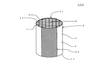
- honeycomb structure One embodiment of the honeycomb structure of the present invention is a tubular honeycomb structure having a porous partition wall 1 and an outer peripheral wall 3 located at the outermost periphery, as in the honeycomb structure 100 shown in FIGS. Part 4 and a pair of electrode parts 21, 21 arranged on side surface 5 of honeycomb structure part 4.
- the partition wall 1 partitions and forms a plurality of cells 2 "extending from one end surface 11 to the other end surface 12 serving as a fluid flow path".
- the honeycomb structure portion 4 has an electrical resistivity of 1 to 200 ⁇ cm.
- Each of the pair of electrode portions 21 and 21 of the honeycomb structure 100 is formed in a strip shape extending in the extending direction of the cells 2 of the honeycomb structure portion 4.
- FIG. 1 is a perspective view schematically showing one embodiment of a honeycomb structure of the present invention.
- Fig. 2 is a schematic diagram showing a cross section parallel to the cell extending direction of one embodiment of the honeycomb structure of the present invention.
- FIG. 3 is a schematic view showing a cross section perpendicular to the cell extending direction of one embodiment of the honeycomb structure of the present invention. In FIG. 3, the partition walls are omitted.
- the electrical resistivity of the honeycomb structure portion 4 is 1 to 200 ⁇ cm. Therefore, even if a current is supplied using a high voltage power source, the current does not flow excessively and can be suitably used as a heater.
- each of the pair of electrode portions 21 and 21 is formed in a band shape, and one electrode portion 21 is opposite to the other electrode portion 21 with the center of the honeycomb structure portion 4 interposed therebetween. It is arranged on the side. Therefore, it is possible to suppress an uneven temperature distribution of the honeycomb structure portion 4 when a voltage is applied between the pair of electrode portions 21 and 21.
- the total heat capacity of the pair of electrode portions 21 and 21 is 2 to 150% of the heat capacity of the entire outer peripheral wall 3. Therefore, it is possible to suppress the occurrence of large stress in the honeycomb structure portion 4 when there is rapid heating or rapid cooling.
- one electrode portion 21 in the pair of electrode portions 21, 21 is more than the other electrode portion 21 in the pair of electrode portions 21, 21.
- “Disposed on the opposite side across the center O” is defined as follows. In other words, in the cross section perpendicular to the extending direction of the cell 2, the positional relationship is such that the angle ⁇ formed by the line segment (A) and the line segment (B) is in the range of 170 ° to 190 °. This means that the pair of electrode portions 21 and 21 are disposed in the honeycomb structure portion 4.
- the line segment (A) is a line segment connecting the center point of one electrode portion 21 (the center point in the “circumferential direction of the honeycomb structure portion 4”) and the center O of the honeycomb structure portion 4.
- the line segment (B) is a line segment connecting the center point of the other electrode portion 21 (the center point in the “circumferential direction of the honeycomb structure portion 4”) and the center O of the honeycomb structure portion 4.
- the angle ⁇ is an angle centered on the “center O”.
- the material of the partition walls 1 and the outer peripheral wall 3 is preferably a silicon-silicon carbide composite material or a silicon carbide material as a main component, and a silicon-silicon carbide composite material or More preferably, it is a silicon carbide material.
- the material of the partition wall 1 and the outer peripheral wall 3 is mainly composed of a silicon-silicon carbide composite material or a silicon carbide material
- the partition wall 1 and the outer peripheral wall 3 are formed of a silicon-silicon carbide composite material or carbonized carbon. It means that 90% by mass or more of the silicon material is contained.
- the electrical resistivity of the honeycomb structure portion can be set to 1 to 200 ⁇ cm.
- the silicon-silicon carbide composite material contains silicon carbide particles as an aggregate and silicon as a binder for bonding the silicon carbide particles.
- the plurality of silicon carbide particles are preferably bonded by silicon so as to form pores between the silicon carbide particles.
- the silicon carbide material is obtained by sintering silicon carbide particles.
- the electrical resistivity of the honeycomb structure part is a value at 400 ° C.
- a pair of electrode portions 21 and 21 are disposed on the side surface 5 of the honeycomb structure portion 4 (the surface of the outer peripheral wall 3).
- the honeycomb structure 100 of the present embodiment generates heat when a voltage is applied between the pair of electrode portions 21 and 21.
- the applied voltage is preferably 12 to 900V, and more preferably 64 to 600V.
- each of the pair of electrode portions 21 and 21 is formed in a strip shape extending in the direction in which the cells 2 of the honeycomb structure portion 4 extend.
- one electrode portion 21 in the pair of electrode portions 21, 21 has a honeycomb structure with respect to the other electrode portion 21 in the pair of electrode portions 21, 21. It is arranged on the opposite side across the central portion O of the portion 4.
- 0.5 times the central angle ⁇ is preferably 15 to 65 °, and more preferably 30 to 60 °.
- the central angle ⁇ is a central angle of each of the electrode portions 21 and 21 in a cross section orthogonal to the extending direction of the cell 2.
- 0.5 times the central angle ⁇ means an angle ⁇ that is 0.5 times the central angle ⁇ .
- the center angle ⁇ of each electrode portion 21, 21 is 0.5.
- the double angle ⁇ is 15 to 65 °.
- the central angle ⁇ of the electrode portion 21 is two lines connecting the both ends of the electrode portion 21 and the center O of the honeycomb structure portion 4 in a cross section orthogonal to the extending direction of the cell 2.
- the above “angle formed by two line segments” refers to the shape formed by the electrode part 21, the line segment (a), and the line segment (b) in the cross section orthogonal to the extending direction of the cell 2 (for example, , A sector shape) is an inner angle of the center O portion.
- the line segment (a) is a line segment connecting one end of the electrode portion 21 and the center O.
- the line segment (b) is a line segment connecting the other end of the electrode portion 21 and the center O.
- the “angle ⁇ that is 0.5 times the central angle ⁇ ” of the one electrode portion 21 is 0.8 ⁇
- the size is preferably 1.2 times, and more preferably 1.0 times the size (the same size).
- the electrode portion 21 has a shape in which a planar rectangular member is curved along the outer periphery of a cylindrical shape. It has become.
- the shape when the curved electrode portion 21 is deformed so as to be a flat member that is not curved is referred to as a “planar shape” of the electrode portion 21.
- the “planar shape” of the electrode portion 21 shown in FIGS. 1 to 3 is a rectangle.
- the outer peripheral shape of the electrode part means “the outer peripheral shape in the planar shape of the electrode part”.
- the outer peripheral shape of the strip-shaped electrode portion 21 may be rectangular.
- the outer peripheral shape of the strip-shaped electrode portion 21 is “a shape in which rectangular corners are formed in a curved shape”.
- the outer peripheral shape of the strip-shaped electrode portion 21 is “a shape in which rectangular corner portions are linearly chamfered”.
- a combined application of “curved” and “linear” is also preferred.
- the outer peripheral shape of the strip-shaped electrode portion 21 is a rectangle, at least one of the corners is a “shape formed in a curved shape”, and at least one of the corners is “straightly chamfered” It is also preferable that the shape is a “shape”.
- the “strip shape” in this specification can also be referred to as a sheet shape or a film shape. That is, the “electrode part” in the present specification does not include the one that protrudes outward like the “electrode terminal protrusion” in the present specification.
- the outer peripheral shape of the electrode portion 21 is “a shape in which rectangular corners are curved” or “a shape in which rectangular corners are chamfered linearly”. It is possible to further improve the thermal shock resistance.
- the corner portion of the electrode portion is a right angle, the stress in the vicinity of the “corner portion of the electrode portion” in the honeycomb structure portion tends to be relatively high as compared with other portions.
- the corners of the electrode parts are curved or chamfered in a straight line, the stress in the vicinity of the “corner parts of the electrode parts” in the honeycomb structure part can be reduced.
- the electrode portion does not have “a corner portion having an“ inner angle of less than 90 ° ””.
- the electrode portion has a “corner portion with an“ inner angle of less than 90 ° ””
- when a thermal shock is applied to the honeycomb structure in the vicinity of the “corner portion with an inner angle of less than 90 °” of the electrode portion. This is because high stress is easily applied to the honeycomb structure portion.
- a pair of electrode portions are disposed on the side surface of the cylindrical honeycomb structure portion.
- a current flows in a direction orthogonal to the cell extending direction of the honeycomb structure portion (or a direction close to the orthogonal direction).
- the electrode portion is disposed on the side surface of the honeycomb structure portion. Therefore, heat accumulates in the portion of the outer peripheral wall where the electrode portion is disposed, and a temperature difference is likely to occur between the portion of the outer peripheral wall where the electrode portion is not disposed. Therefore, the thermal shock resistance of the honeycomb structure may be reduced.
- the total heat capacity of the pair of electrode portions is 2 to 150% of the heat capacity of the entire outer peripheral wall.
- the total heat capacity of the pair of electrode portions is preferably less than or equal to the heat capacity of the entire outer peripheral wall (that is, 2 to 100%), and more preferably smaller than the heat capacity of the entire outer peripheral wall.
- the sum of the heat capacities of the pair of electrode portions is a value derived by a heat capacity calculation method that takes into account the porosity, the specific gravity of the material, and the specific heat based on the volume of the electrode portions.
- the “volume of the electrode part” is the volume of the electrode part calculated using the average thickness of the electrode part and the electrode angle (center angle ⁇ in FIG. 3) measured with an optical microscope.
- the heat capacity of the entire outer peripheral wall is a value derived by a heat capacity calculation method that takes into account the porosity, the specific gravity of the material, and the specific heat based on the volume of the outer peripheral wall.
- the “volume of the outer peripheral wall” refers to the volume of the outer peripheral wall calculated using the average thickness of the outer peripheral wall measured with an optical microscope.
- contact area of the electrode portion the area of the portion where the electrode portion is in contact with the side surface of the honeycomb structure portion.
- a cylinder that is coaxial with the honeycomb structure part and divides the electrode part is assumed, and a divided surface of the electrode part divided into the cylinder is defined as a virtual divided surface.
- the area of this virtual division plane is referred to as “virtual division area”.
- the “virtual division” is used in the calculation of the “heat capacity of the electrode portion” in the present specification.
- a portion where the “area” is 90% or more of the “contact area of the electrode portion” is referred to as an “electrode portion”. That is, in the above case, when calculating the “heat capacity of the electrode part” in this specification, the part where the “virtual divided area” is less than 90% of the “contact area of the electrode part” is not an electrode part.
- the total heat capacity of the pair of electrode portions is smaller than the heat capacity of the entire outer peripheral wall
- the total heat capacity of the pair of electrode portions is the entire outer wall. It is preferably 2 to 80% of the heat capacity.
- the lower limit is more preferably 9%, and particularly preferably 15%.
- the upper limit value is more preferably 75%, and particularly preferably 50%. If it is less than 2%, the effect of “more uniformly flowing the current through the entire honeycomb structure when a voltage is applied” may be reduced. If it exceeds 80%, the effect of reducing the thermal shock resistance may be reduced.
- the thickness of the pair of electrode portions is preferably 5 to 200%, more preferably 5 to 140% of the thickness of the outer peripheral wall of the honeycomb structure portion. It is particularly preferably 5 to 100%.
- the heat capacity of the electrode portion can be made lower than the heat capacity of the outer peripheral wall of the honeycomb structure portion. Therefore, the thermal shock resistance of the honeycomb structure can be improved. If the thickness of the electrode portion is less than 5% of the thickness of the outer peripheral wall of the honeycomb structure portion, it may be difficult to flow a current uniformly through the honeycomb structure portion. If the thickness of the electrode part is larger than 200% of the thickness of the outer peripheral wall of the honeycomb structure part, it may be difficult to reduce the heat capacity of the electrode part.
- the thickness of the electrode part is a value measured with an optical microscope. Specifically, it is the value of the average thickness at three points in the circumferential direction of the electrode part in “the central part of the honeycomb structure in the cell extending direction”.
- the “value of the average thickness at three points in the circumferential direction of the electrode portion” is a value defined as follows. That is, the electrode part is divided into three parts in the “circumferential direction of the honeycomb structure part” to form three divided parts, and the thickness of the central part in the “circumferential direction of the honeycomb structure part” is measured in each divided part to obtain It is the value which averaged the measurement result of thickness of 3 points
- the above-mentioned “dividing the electrode part into three equal parts in the“ circumferential direction of the honeycomb structure part ” means that the electrode part is divided into three equal parts by a straight line parallel to the cell extending direction.
- the thickness of the outer peripheral wall of the honeycomb structure is a value measured with an optical microscope. Specifically, it is the value of the average thickness at eight points in the circumferential direction of the outer peripheral wall in “the central portion of the honeycomb structure in the cell extending direction”.
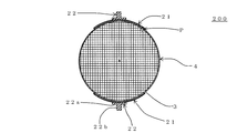
- the “eight points in the circumferential direction of the outer peripheral wall” is defined as follows. That is, as shown in FIG. 12, in the “cross section orthogonal to the cell extending direction” of the honeycomb structure portion 4, four straight lines L 1, L 2, L 3, and L 4 are the straight lines of the honeycomb structure portion 4. The eight points intersecting the outer peripheral wall 3.
- the straight line L1 is a straight line that passes through the center O and is parallel to one partition.
- the straight line L2 is a straight line passing through the center O and having an angle of 45 ° with the straight line L1.
- the straight line L3 is a straight line that passes through the center O and has an angle of 45 ° with the straight line L2 (an angle with the straight line L1 is 90 °).
- the straight line L4 is a straight line that passes through the center O and has an angle of 45 ° with the straight line L3 (an angle with the straight line L2 is 90 °).
- FIG. 12 is a schematic view showing a cross section perpendicular to the cell extending direction of one embodiment (honeycomb structure 100) of the honeycomb structure of the present invention.
- the electrode part is omitted.
- the thickness of the pair of electrode portions is preferably 0.025 to 1.0 mm, more preferably 0.025 to 0.7 mm, and 0.05 to A thickness of 0.5 mm is particularly preferable.
- the thickness of the electrode part is less than 0.025 mm, it may be difficult to flow a current uniformly through the honeycomb structure part.
- the thickness of the electrode part is greater than 1.0 mm, it may be difficult to reduce the heat capacity of the electrode part.
- the thickness of the outer peripheral wall of the honeycomb structure portion is preferably 0.1 to 1.0 mm, more preferably 0.2 to 0.8 mm, It is particularly preferred that the thickness is 0.5 mm.
- the thermal shock resistance of the honeycomb structure can be improved. In addition, this makes it possible to suppress an excessive increase in pressure loss when exhaust gas flows even when the honeycomb structure is used as a catalyst carrier and a catalyst is supported. If the thickness of the outer peripheral wall of the honeycomb structure is thinner than 0.1 mm, the strength of the honeycomb structure may be lowered.
- the thermal shock resistance of the honeycomb structure may be lowered. If the thickness of the outer peripheral wall of the honeycomb structure is greater than 1.0 mm, the area of the partition walls supporting the catalyst may be reduced when the catalyst is supported using the honeycomb structure as a catalyst carrier.
- the porosity of the pair of electrode portions is preferably 0.75 to 2 times the porosity of the outer peripheral wall of the honeycomb structure portion.
- Condition (V) is: “The thickness of the pair of electrode portions is 5 to 200% of the thickness of the outer peripheral wall of the honeycomb structure portion, and the thickness of the pair of electrode portions is 0.025 to 1. 0 mm ".
- the porosity of the pair of electrode portions is preferably 30 to 80%.
- the porosity of the pair of electrode portions is preferably 0.75 to 2 times the porosity of the outer peripheral wall of the honeycomb structure portion, and more preferably 1 to 2 times.
- the ratio is preferably 1 to 1.75 times.
- the porosity of the electrode part is smaller than 0.75 times the porosity of the outer peripheral wall of the honeycomb structure part, it may be difficult to make the heat capacity of the electrode part lower than the heat capacity of the outer peripheral wall. If the porosity of the electrode part is larger than twice the porosity of the outer peripheral wall of the honeycomb structure part, it may be difficult to flow a current uniformly through the honeycomb structure part.
- the porosity of an electrode part and an outer peripheral wall is the value measured with the mercury porosimeter.
- the porosity of the pair of electrode portions is preferably 30 to 80%, more preferably 30 to 70%, and particularly preferably 30 to 60%. .
- the porosity of the electrode part is in such a range, the heat capacity of the electrode part can be lowered. Therefore, the thermal shock resistance of the honeycomb structure can be improved.
- the porosity of the electrode part is smaller than 30%, it may be difficult to reduce the heat capacity of the electrode part.
- the porosity of the electrode part is greater than 80%, it may be difficult to flow a current uniformly through the honeycomb structure part. Further, if the porosity of the electrode part is larger than 80%, the electrical resistivity of the electrode part may become too high.
- the porosity of the outer peripheral wall of the honeycomb structure portion is preferably 35 to 60%, more preferably 35 to 55%, and more preferably 35 to 50%. Particularly preferred.
- the porosity of the outer peripheral wall of the honeycomb structure is within such a range, the thermal shock resistance of the honeycomb structure can be improved. If the porosity of the outer peripheral wall of the honeycomb structure is less than 35%, the effect of improving the thermal shock resistance of the honeycomb structure may be reduced. If the porosity of the outer peripheral wall of the honeycomb structure is larger than 60%, the mechanical strength of the honeycomb structure may be lowered.
- the thickness of the pair of electrode portions is preferably 5 to 200% of the thickness of the outer peripheral wall of the honeycomb structure portion.
- Condition (W) is: “The porosity of the pair of electrode portions is 0.75 to 2 times the porosity of the outer peripheral wall of the honeycomb structure portion, and the porosity of the pair of electrode portions is 30 to 80%. Is. At this time, the thickness of the pair of electrode portions is preferably 0.025 to 1.0 mm. Thereby, while improving the thermal shock resistance of a honeycomb structure, the effect of flowing an electric current uniformly can be exhibited more effectively.
- the electrical resistivity of the electrode portion 21 may be uniform or may be partially different.
- the electrical resistivity of the electrode portion 21 is preferably 0.01 to 100 ⁇ cm, more preferably 0.1 to 100 ⁇ cm, and more preferably 0.1 to 50 ⁇ cm. It is particularly preferred that By setting the electrical resistivity of the electrode portion 21 in such a range, the pair of electrode portions 21 and 21 effectively serve as electrodes in the pipe through which the high-temperature exhaust gas flows.
- the electrical resistivity of the electrode part 21 is smaller than 0.01 ⁇ cm, the temperature of the honeycomb structure part near both ends of the electrode part 21 may easily rise in a cross section orthogonal to the cell extending direction. If the electrical resistivity of the electrode portion 21 is larger than 100 ⁇ cm, it may be difficult to play a role as an electrode because current hardly flows.
- the electrical resistivity of the electrode part is a value at 400 ° C.
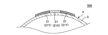
- the electrode part 21 is composed of a central part 21X and expansion parts 21Y and 21Y as in the honeycomb structure 500 shown in FIGS. It is preferable that the electrical resistivity of the central portion 21X of the 21 is smaller than the electrical resistivity of the extended portions 21Y and 21Y of the electrode portion 21.
- the central portion 21 ⁇ / b> X is a portion in the circumferential direction of the electrode portion 21 in a cross section orthogonal to the extending direction of the cell 2.
- the extended portions 21Y and 21Y are portions located on both sides in the circumferential direction of the central portion 21X in a cross section orthogonal to the extending direction of the cells 2.
- FIG. 4 is a front view schematically showing another embodiment of the honeycomb structure of the present invention.
- FIG. 5 is a schematic view showing a cross section perpendicular to the cell extending direction of another embodiment of the honeycomb structure of the present invention.
- the electrical resistivity of the central portion 21X is preferably 0.0001 to 70%, more preferably 0.001 to 50%, and particularly preferably 0.001 to 10% of the electrical resistivity of the extended portions 21Y and 21Y. If it is less than 0.0001%, the flow of current in the outer peripheral direction in the cross section perpendicular to the central axis of the honeycomb structure portion becomes small, and the deviation in temperature distribution may become large. If it is larger than 70%, the effect of suppressing the uneven temperature distribution of the honeycomb structure 400 may be reduced.
- the Young's modulus of the electrode portion 21 is preferably 2 to 50 GPa, more preferably 3 to 45 GPa, and particularly preferably 3 to 35 GPa.
- the Young's modulus of the electrode part 21 is preferably 2 to 50 GPa, more preferably 3 to 45 GPa, and particularly preferably 3 to 35 GPa.
- the Young's modulus may be uniform within the electrode portion 21 or may be partially different. When the Young's modulus is partially different, the above effect can be obtained if a part is within the above range, and the above effect is further enhanced if all are within the above range.
- the Young's modulus of the electrode part is a value measured by a bending resonance method in accordance with JIS R1602. As a test piece used for measurement, after a plurality of sheets made of electrode part forming raw materials for forming an electrode part were stacked to obtain a laminate, the laminate was dried and cut into a size of 3 mm ⁇ 4 mm ⁇ 40 mm. Use things.
- the electrode portion 21 is preferably mainly composed of silicon carbide particles and silicon, and more preferably formed from silicon carbide particles and silicon as raw materials except for impurities that are usually contained.
- “mainly composed of silicon carbide particles and silicon” means that the total mass of the silicon carbide particles and silicon is 90% by mass or more of the mass of the entire electrode portion.
- the component of the electrode part 21 and the component of the honeycomb structure part 4 are the same component or a close component (the material of the honeycomb structure part is silicon carbide). If there is). Therefore, the thermal expansion coefficients of the electrode part 21 and the honeycomb structure part 4 are the same value or close values.
- the bonding strength between the electrode part 21 and the honeycomb structure part 4 is also increased. Therefore, even when thermal stress is applied to the honeycomb structure, it is possible to prevent the electrode portion 21 from being peeled off from the honeycomb structure portion 4 and the joint portion between the electrode portion 21 and the honeycomb structure portion 4 being damaged.
- the electrode part 21 preferably has an average pore diameter of 5 to 45 ⁇ m, more preferably 7 to 40 ⁇ m.
- the average pore diameter of the electrode part 21 is in such a range, a suitable electrical resistivity can be obtained. If the average pore diameter of the electrode part 21 is smaller than 5 ⁇ m, the electrical resistivity may be too high. When the average pore diameter of the electrode part 21 is larger than 40 ⁇ m, the strength of the electrode part 21 is weakened and may be easily damaged.
- the average pore diameter is a value measured with a mercury porosimeter.
- the average particle diameter of the silicon carbide particles contained in the electrode part 21 is preferably 10 to 70 ⁇ m, and more preferably 10 to 60 ⁇ m. .
- the electrical resistivity of the electrode portion 21 can be controlled in the range of 0.1 to 100 ⁇ cm. If the average pore diameter of the silicon carbide particles contained in the electrode part 21 is smaller than 10 ⁇ m, the electrical resistivity of the electrode part 21 may become too large. When the average pore diameter of the silicon carbide particles contained in the electrode portion 21 is larger than 70 ⁇ m, the strength of the electrode portion 21 is weakened and may be easily damaged.
- the average particle diameter of the silicon carbide particles contained in the electrode part 21 is a value measured by a laser diffraction method.
- the ratio of the mass of silicon contained in the electrode part 21 to the “total of the respective masses of silicon carbide particles and silicon” contained in the electrode part 21 is preferably 20 to 50% by mass, and preferably 20 to 40%. More preferably, it is mass%.
- the electrical resistivity of electrode portion 21 is 0.1 to 100 ⁇ cm. Can be controlled by range. If the ratio of the mass of silicon to the total mass of silicon carbide particles and silicon contained in the electrode portion 21 is less than 20% by mass, the electrical resistivity may be too large. If it is larger than 50% by mass, it may be easily deformed during production.
- the partition wall thickness is 50 to 260 ⁇ m, and preferably 70 to 180 ⁇ m.
- the partition wall thickness is 50 to 260 ⁇ m, and preferably 70 to 180 ⁇ m.
- the honeycomb structure 100 of the present embodiment preferably has a cell density of 40 to 150 cells / cm 2 , and more preferably 70 to 100 cells / cm 2 .
- the purification performance of the catalyst can be enhanced while reducing the pressure loss when the exhaust gas is flowed.
- the cell density is lower than 40 cells / cm 2 , the catalyst supporting area may be reduced.
- the cell density is higher than 150 cells / cm 2 , when the honeycomb structure 100 is used as a catalyst carrier and a catalyst is supported, the pressure loss when the exhaust gas flows may increase.
- the average particle diameter of the silicon carbide particles (aggregate) constituting the honeycomb structure portion 4 is preferably 3 to 50 ⁇ m, and more preferably 3 to 40 ⁇ m.
- the electrical resistivity at 400 ° C. of the honeycomb structure part 4 can be 1 to 200 ⁇ cm.
- the electrical resistivity of the honeycomb structure portion 4 may be increased.
- the electrical resistivity of the honeycomb structure portion 4 may be reduced.
- the extrusion forming die may be clogged with the forming raw material when the honeycomb formed body is extruded.
- the average particle diameter of the silicon carbide particles is a value measured by a laser diffraction method.
- the electrical resistivity of the honeycomb structure portion 4 is 1 to 200 ⁇ cm, and preferably 40 to 100 ⁇ cm.
- the electrical resistivity is smaller than 1 ⁇ cm, for example, when the honeycomb structure 100 is energized by a high-voltage power supply of 200 V or higher, an excessive current may flow.
- the electrical resistivity is greater than 200 ⁇ cm, for example, when the honeycomb structure 100 is energized by a high-voltage power supply of 200 V or higher, it becomes difficult for current to flow, and heat generation may not occur sufficiently.
- the electrical resistivity of the honeycomb structure part is a value measured by a four-terminal method.
- the electrical resistivity of the honeycomb structure part is a value at 400 ° C.
- the electrical resistivity of the electrode portion 21 is lower than the electrical resistivity of the honeycomb structure portion 4. Furthermore, the electrical resistivity of the electrode portion 21 is more preferably 20% or less, and particularly preferably 1 to 10% of the electrical resistivity of the honeycomb structure portion 4. By setting the electrical resistivity of the electrode part 21 to 20% or less of the electrical resistivity of the honeycomb structure part 4, the electrode part 21 functions more effectively as an electrode.
- the “mass of silicon carbide particles” and the “mass of silicon” have the following relationship: Is preferred. That is, the ratio of “mass of silicon” to the total of “mass of silicon carbide particles” and “mass of silicon” is preferably 10 to 40% by mass, and more preferably 15 to 35% by mass. preferable. If it is lower than 10% by mass, the strength of the honeycomb structure may be lowered. If it is higher than 40% by mass, the shape may not be maintained during firing.
- the above “mass of silicon carbide particles” refers to “mass of silicon carbide particles as an aggregate” contained in the honeycomb structure portion 4.
- the above “mass of silicon” refers to “mass of silicon as a binder” contained in the honeycomb structure 4.
- the porosity of the partition walls 1 of the honeycomb structure portion 4 is preferably 35 to 60%, and more preferably 45 to 55%. If the porosity is less than 35%, deformation during firing may increase. When the porosity exceeds 60%, the strength of the honeycomb structure may be lowered.
- the porosity is a value measured with a mercury porosimeter.
- the average pore diameter of the partition walls 1 of the honeycomb structure part 4 is preferably 2 to 15 ⁇ m, and more preferably 4 to 8 ⁇ m. If the average pore diameter is smaller than 2 ⁇ m, the electrical resistivity may become too large. If the average pore diameter is larger than 15 ⁇ m, the electrical resistivity may be too small.
- the average pore diameter is a value measured with a mercury porosimeter.
- the shape of the cell 2 in a cross section perpendicular to the extending direction of the cell 2 is a quadrangle, a hexagon, an octagon, or a combination thereof.
- the shape of the honeycomb structure 100 of the present embodiment is not particularly limited.
- the bottom surface may have a circular cylindrical shape (cylindrical shape), the bottom surface may have an oval cylindrical shape, and the bottom surface may have a polygonal shape (square, pentagon, hexagon, heptagon, octagon, etc.). it can.
- the honeycomb structure has a bottom surface area of preferably 2000 to 20000 mm 2 , and more preferably 4000 to 10000 mm 2 .
- the length of the honeycomb structure in the central axis direction (cell extending direction) is preferably 50 to 200 mm, and more preferably 75 to 150 mm.
- the isostatic strength of the honeycomb structure 100 of the present embodiment is preferably 1 MPa or more, and more preferably 3 MPa or more. The larger the value of isostatic strength, the better. Considering the material and structure of the honeycomb structure 100, the upper limit is about 6 MPa. When the isostatic strength is less than 1 MPa, the honeycomb structure may be easily damaged when used as a catalyst carrier or the like. Isostatic strength is a value measured by applying hydrostatic pressure in water.
- the honeycomb structure 100 of the present embodiment has a pair of electrode portions 21 and 21 extending in the direction in which the cells 2 of the honeycomb structure portion 4 extend and “between both ends ( It is formed in a strip shape extending between both end faces 11 and 12).
- the pair of electrode portions 21 and 21 are disposed so as to extend between both ends of the honeycomb structure portion 4, so that when a voltage is applied between the pair of electrode portions 21 and 21, the honeycomb structure
- the bias of the current flowing through the portion 4 can be more effectively suppressed.
- the electrode portion 21 is formed (arranged) so as to extend between both end portions of the honeycomb structure portion 4” means that the following condition (X) is satisfied.
- Condition (X) is: “One end of the electrode part 21 is in contact with one end (one end face) of the honeycomb structure 4, and the other end of the electrode part 21 is the other end of the honeycomb structure 4. Part (the other end face) ".
- both end portions 21 a and 21 b of the electrode portion 21 in the “extending direction of the cells 2 of the honeycomb structure portion 4” are both end portions (both end surfaces 11 and 12 of the honeycomb structure portion 4). ) May not be in contact (not reached).
- one end portion 21 a of the electrode portion 21 is in contact with (reaches) one end portion (one end surface 11) of the honeycomb structure portion 4, and the other end portion 21 b is the other end of the honeycomb structure portion 4.
- the following distance D1 is from one end portion 21a of the remaining one electrode portion 21 of the pair of electrode portions 21 and 21 to "one end portion (one end surface 11) of the honeycomb structure portion 4".
- the distance is preferably the same, but may be different.
- the distance D1 is a distance from one end portion 21a of one electrode portion 21 of the pair of electrode portions 21 and 21 to "one end portion (one end surface 11) of the honeycomb structure portion 4".
- the following distance D2 is from the other end 21b of the remaining one electrode portion 21 of the pair of electrode portions 21 and 21 to the “other end portion (the other end surface 12) of the honeycomb structure portion 4”.
- the distance is preferably the same, but may be different.
- the distance D2 is a distance from the other end portion 21b of one electrode portion 21 of the pair of electrode portions 21 and 21 to "the other end portion (the other end face 12) of the honeycomb structure portion 4". It is.
- One end 21 a of the electrode portion 21 is an end facing the one end portion (one end surface 11) side of the honeycomb structure portion 4.
- the other end portion 21 b of the electrode portion 21 is an end portion facing the other end portion (the other end surface 12) side of the honeycomb structure portion 4.
- FIG. 9 is a perspective view schematically showing another embodiment (honeycomb structure 300) of the honeycomb structure of the present invention.
- each condition of the honeycomb structure 300 of the present embodiment is preferably the same as each condition in the embodiment (honeycomb structure 100) of the honeycomb structure of the present invention, except for the following condition (Y).
- the condition (Y) is “at least one end of the electrode portion 21 is not in contact with (has reached) the end (end surface) of the honeycomb structure 4”.
- the distance D3 is the length in the extending direction of the cells 2 of the honeycomb structure portion 4. It is preferably shorter than 50%, more preferably 25% or less. If it is 50% or more, when a voltage is applied between the pair of electrode parts 21 and 21, it may be difficult to suppress the bias of the current flowing in the honeycomb structure part 4.
- the distance D3 is a distance between “an end portion of the electrode portion 21” that is not in contact with the end portion (end surface) of the honeycomb structure portion 4 and “an end portion (end surface) of the honeycomb structure portion”.
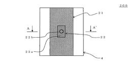
- the honeycomb structure 200 of the present embodiment is an electrode terminal protrusion 22 for connecting electric wirings in the honeycomb structure 100 of the present invention (see FIGS. 1 to 3). Is arranged.
- the electrode terminal protrusion 22 is a central portion of each electrode portion 21, 21 in the cross section perpendicular to the cell extending direction, and is disposed in the central portion in the cell extending direction.
- the electrode terminal protrusion 22 is a portion for connecting a wiring from a power source in order to apply a voltage between the electrode portions 21 and 21.
- FIG. 6 is a front view schematically showing still another embodiment of the honeycomb structure of the present invention.
- FIG. 7 is a schematic diagram showing an A-A ′ cross section in FIG. 6.
- Fig. 8 is a side view schematically showing still another embodiment of the honeycomb structure of the present invention.
- the conditions of the honeycomb structure 200 of the present embodiment are the same as the conditions in the embodiment of the honeycomb structure of the present invention (the honeycomb structure 100 (see FIGS. 1 to 3)) except for the following condition (Z). Preferably they are the same.
- the condition (Z) is “the electrode terminal for connecting the electric wiring to the center part of each electrode part 21, 21 in the cross section perpendicular to the extending direction of the cell 2 and to the center part in the extending direction of the cell 2.
- the protrusion 22 is disposed.
- the “central portion in the cross section perpendicular to the extending direction of the cells 2” refers to the central portion in the “peripheral direction of the honeycomb structure portion”.
- the main components of the electrode terminal protrusion 22 are also preferably silicon carbide particles and silicon.
- the electrode terminal protrusion 22 has silicon carbide particles and silicon as main components, the component of the electrode part 21 and the component of the electrode terminal protrusion 22 are the same (or close) components. Therefore, the thermal expansion coefficient of the electrode part 21 and the electrode terminal protrusion part 22 becomes the same (or close) value.
- the material of the electrode part 21 and the material of the electrode terminal protrusion part 22 become the same (or close), the joining strength of the electrode part 21 and the electrode terminal protrusion part 22 also becomes high.
- the electrode terminal protrusion 22 when “the electrode terminal protrusion 22 is composed mainly of silicon carbide particles and silicon”, the electrode terminal protrusion 22 contains 90% by mass or more of silicon carbide particles and silicon. Means that.
- the shape of the electrode terminal protrusion 22 is not particularly limited as long as it can be bonded to the electrode 21 and can be connected to the electric wiring.
- the electrode terminal protrusion 22 preferably has a shape in which a cylindrical protrusion 22b is disposed on a rectangular plate-like substrate 22a. With this shape, the electrode terminal protrusion 22 can be firmly bonded to the electrode portion 21 by the substrate 22a. Then, the electrical wiring can be reliably bonded by the protrusion 22b.
- the thickness of the substrate 22a is preferably 1 to 5 mm. By setting it as such thickness, the electrode terminal protrusion part 22 can be joined to the electrode part 21 reliably. If it is thinner than 1 mm, the substrate 22a becomes weak, and the protrusion 22b may be easily detached from the substrate 22a. If it is thicker than 5 mm, the space for arranging the honeycomb structure may become larger than necessary.
- the length (width) of the substrate 22 a is preferably 10 to 50%, more preferably 20 to 40% of the length of the electrode portion 21. By setting it as such a range, the electrode terminal protrusion part 22 becomes difficult to remove
- the “length (width) of the substrate 22a” is the length of the substrate 22a in the “peripheral direction in the cross section perpendicular to the cell extending direction of the honeycomb structure portion 4”.
- the “length of the electrode part 21” is the length of the electrode part 21 in “the outer peripheral direction (direction along the outer periphery) in the cross section of the honeycomb structure part 4 orthogonal to the cell extending direction”.
- the length of the substrate 22a in the “cell 2 extending direction” is preferably 5 to 30% of the length of the honeycomb structure 4 in the cell extending direction. By setting the length of the substrate 22a in the “direction in which the cells 2 extend” within such a range, sufficient bonding strength can be obtained. If the length of the substrate 22 a in the “cell 2 extending direction” is shorter than 5% of the length of the honeycomb structure portion 4 in the cell extending direction, the substrate 22 a may be easily detached from the electrode portion 21. And if it is longer than 30%, the mass may increase.
- the thickness of the protrusion 22b is preferably 3 to 15 mm. With such a thickness, the electrical wiring can be reliably bonded to the protrusion 22b. If it is thinner than 3 mm, the protrusion 22b may be easily broken. If it is thicker than 15 mm, it may be difficult to connect the electrical wiring.
- the length of the protrusion 22b is preferably 3 to 20 mm. With such a length, the electrical wiring can be reliably bonded to the protrusion 22b. If it is shorter than 3 mm, it may be difficult to join the electric wiring. If it is longer than 20 mm, the protrusion 22b may be easily broken.
- the electrical resistivity of the electrode terminal protrusion 22 is preferably 0.1 to 2.0 ⁇ cm, and more preferably 0.1 to 1.0 ⁇ cm. By setting the electrical resistivity of the electrode terminal protrusion 22 in such a range, current can be efficiently supplied from the electrode terminal protrusion 22 to the electrode portion 21 in the pipe through which high-temperature exhaust gas flows. If the electrical resistivity of the electrode terminal protrusion 22 is greater than 2.0 ⁇ cm, it may be difficult to supply current to the electrode portion 21 because current does not flow easily.
- the electrode terminal protrusion 22 preferably has a porosity of 30 to 45%, and more preferably 30 to 40%. When the porosity of the electrode terminal protrusion 22 is within such a range, an appropriate electrical resistivity can be obtained. If the porosity of the electrode terminal protrusion 22 is higher than 45%, the strength of the electrode terminal protrusion 22 may be reduced. In particular, when the strength of the protrusion 22b is lowered, the protrusion 22b may be easily broken.
- the porosity is a value measured with a mercury porosimeter.
- the electrode terminal protrusion 22 preferably has an average pore diameter of 5 to 20 ⁇ m, and more preferably 7 to 15 ⁇ m. When the average pore diameter of the electrode terminal protrusion 22 is within such a range, an appropriate electrical resistivity can be obtained. If the average pore diameter of the electrode terminal protrusion 22 is larger than 20 ⁇ m, the strength of the electrode terminal protrusion 22 may be reduced. In particular, when the strength of the protrusion 22b is lowered, the protrusion 22b may be easily broken.
- the average pore diameter is a value measured with a mercury porosimeter.
- the average particle diameter of the silicon carbide particles contained in the electrode terminal protrusion 22 is preferably 10 to 60 ⁇ m, and preferably 20 to 60 ⁇ m. More preferably.
- the electrical resistivity of the electrode terminal protrusion 22 can be set to 0.1 to 2.0 ⁇ cm. If the average pore diameter of the silicon carbide particles contained in the electrode terminal protrusion 22 is smaller than 10 ⁇ m, the electrical resistivity of the electrode terminal protrusion 22 may become too large.
- the average particle diameter of the silicon carbide particles contained in the electrode terminal protrusion 22 is a value measured by a laser diffraction method.
- the ratio of the mass of silicon contained in the electrode terminal projection 22 to the “total mass of silicon carbide particles and silicon” contained in the electrode terminal projection 22 is preferably 20 to 40% by mass. More preferably, the content is 25 to 35% by mass.
- an electrical resistivity of 0.1 to 2.0 ⁇ cm can be obtained. It becomes easy to obtain. If the ratio of the mass of silicon to the total mass of silicon carbide particles and silicon contained in the electrode terminal protrusion 22 is smaller than 20% by mass, the electrical resistivity may become too large. And when larger than 40 mass%, it may deform
- the honeycomb structure 400 (see FIG. 11) of the present embodiment is the same as the above-described embodiment of the honeycomb structure of the present invention (honeycomb structure 100 (see FIGS. 1 to 3)). It is installed on the surface of the electrode part 21.
- the conductor 23 has an electrical resistivity lower than the electrical resistivity of the electrode portion 21. Therefore, it is preferable that the honeycomb structure 400 of the present embodiment has the same conditions as the honeycomb structure 100 of the present invention (see FIGS. 1 to 3) except that the conductor 23 is included.
- FIG. 11 is a front view schematically showing still another embodiment of the honeycomb structure of the present invention.
- the conductor 23 having an electrical resistivity lower than that of the electrode portion 21 is provided on the surface of the electrode portion 21. Therefore, by applying a voltage to the conductor 23, it becomes possible to flow a current more uniformly through the entire honeycomb structure portion.
- the electrical resistivity of the conductor 23 is preferably 0.0001 to 70%, more preferably 0.001 to 50%, and particularly preferably 0.001 to 10% of the electrical resistivity of the electrode portion 21. If it is less than 0.0001%, the flow of current in the outer peripheral direction in the cross section perpendicular to the central axis of the honeycomb structure portion becomes small, and the deviation in temperature distribution may become large. If it is larger than 70%, the effect of suppressing the uneven temperature distribution of the honeycomb structure 400 may be reduced.
- the electrical resistivity is a value at 400 ° C.
- the shape (peripheral shape) of the conductor 23 is not particularly limited. As shown in FIG. 11, it is preferable that the electrode portion has a rectangular shape extending from one end portion 21a of the electrode portion to the other end portion 21b of the electrode portion.
- the conductor 23 may not extend between both end portions of the electrode portion. That is, there may be a gap between the end portion of the conductor 23 and the end portion of the electrode portion.
- the length of the conductor 23 is preferably 50% or more of the length of the electrode portion 21, more preferably 80% or more, and particularly preferably 100%. If it is shorter than 50%, when a voltage is applied, the effect of allowing a current to flow more uniformly through the entire honeycomb structure may be reduced.
- the “length of the conductor 23” is the length of the conductor 23 in the extending direction of the “cells of the honeycomb structure portion”.
- the “length of the electrode portion 21” is the length of the electrode portion 21 in the extending direction of the “cells of the honeycomb structure portion”.
- the length of the conductor 23 in the circumferential direction is not particularly limited as long as it is equal to or shorter than the length in the circumferential direction of the electrode portion.
- the circumferential length of the conductor 23 is preferably 5 to 75%, more preferably 10 to 60% of the circumferential length of the electrode portion. If it is longer than 75%, the temperature of the honeycomb structure near the both ends of the electrode portion 21 may easily rise in the cross section orthogonal to the cell extending direction. If it is shorter than 5%, when a voltage is applied, the effect of causing a current to flow more uniformly over the entire honeycomb structure may be reduced.
- Examples of the material for the conductor 23 include silicon carbide impregnated with silicon and a porosity of 5% or less.
- the thickness of the conductor 23 is preferably 0.1 to 2 mm, more preferably 0.2 to 1.5 mm, and particularly preferably 0.3 to 1 mm. If it is thicker than 2 mm, the thermal shock resistance of the honeycomb structure may be lowered. If it is thinner than 0.1 mm, the strength of the conductor 23 may be reduced.
- the honeycomb structure of the present invention can be used as a catalyst carrier.
- a known catalyst By supporting a known catalyst on the honeycomb structure of the present invention by a known method, it can be used as a catalyst for exhaust gas treatment.
- metal silicon powder metal silicon
- a binder a surfactant, a pore former, water and the like are added to silicon carbide powder (silicon carbide) to produce a forming raw material.
- the mass of the metal silicon is 10 to 40% by mass with respect to the total of the mass of the silicon carbide powder and the mass of the metal silicon.
- the average particle diameter of the silicon carbide particles in the silicon carbide powder is preferably 3 to 50 ⁇ m, and more preferably 3 to 40 ⁇ m.
- the average particle diameter of metal silicon (metal silicon powder) is preferably 2 to 35 ⁇ m.
- the average particle diameter of silicon carbide particles and metal silicon (metal silicon particles) is a value measured by a laser diffraction method.
- Silicon carbide particles are fine particles of silicon carbide constituting silicon carbide powder.
- the metal silicon particles are fine particles of metal silicon constituting the metal silicon powder. This is a composition of a forming raw material when the material of the honeycomb structure part is a silicon-silicon carbide based composite material. When the material of the honeycomb structure is silicon carbide, no metallic silicon is added.
- binder examples include methyl cellulose, hydroxypropyl methyl cellulose, hydroxypropoxyl cellulose, hydroxyethyl cellulose, carboxymethyl cellulose, and polyvinyl alcohol. Among these, it is preferable to use methyl cellulose and hydroxypropoxyl cellulose in combination.
- the content of the binder is preferably 2.0 to 10.0 parts by mass when the total mass of the silicon carbide powder and the metal silicon powder is 100 parts by mass.
- the water content is preferably 20 to 60 parts by mass when the total mass of the silicon carbide powder and the metal silicon powder is 100 parts by mass.
- ethylene glycol, dextrin, fatty acid soap, polyalcohol or the like can be used as the surfactant. These may be used individually by 1 type and may be used in combination of 2 or more type.
- the content of the surfactant is preferably 0.1 to 2.0 parts by mass when the total mass of the silicon carbide powder and the metal silicon powder is 100 parts by mass.
- the pore former is not particularly limited as long as it becomes pores after firing, and examples thereof include graphite, starch, foamed resin, water absorbent resin, silica gel and the like.
- the pore former content is preferably 0.5 to 10.0 parts by mass when the total mass of the silicon carbide powder and the metal silicon powder is 100 parts by mass.
- the average particle size of the pore former is preferably 10 to 30 ⁇ m. If it is smaller than 10 ⁇ m, pores may not be formed sufficiently. If it is larger than 30 ⁇ m, the die may be clogged during molding.
- the average particle diameter of the pore former is a value measured by a laser diffraction method.
- the forming raw material is kneaded to form a clay.
- molding raw material and forming a clay For example, the method of using a kneader, a vacuum clay kneader, etc. can be mentioned.
- the clay is extruded to form a honeycomb formed body.
- a die having a desired overall shape, cell shape, partition wall thickness, cell density and the like.
- a cemented carbide which does not easily wear is preferable.
- the honeycomb formed body has a structure having partition walls that form a plurality of cells that serve as fluid flow paths and an outer peripheral wall that is positioned on the outermost periphery.
- the partition wall thickness, cell density, outer peripheral wall thickness, etc. of the honeycomb molded body can be appropriately determined in accordance with the structure of the honeycomb structure of the present invention to be manufactured in consideration of shrinkage during drying and firing.
- the drying method is not particularly limited, and examples thereof include an electromagnetic heating method such as microwave heating drying and high-frequency dielectric heating drying, and an external heating method such as hot air drying and superheated steam drying. Among these, it is preferable to dry a certain amount of moisture by an electromagnetic heating method and then dry the remaining moisture by an external heating method. This is because the entire molded body can be dried quickly and uniformly without cracks. As drying conditions, it is preferable to remove 30 to 99% by mass of water with respect to the amount of moisture before drying by an electromagnetic heating method, and then to make the moisture to 3% by mass or less by an external heating method. . As the electromagnetic wave heating method, dielectric heating drying is preferable. As an external heating method, hot air drying is preferable.
- the length in the central axis direction of the honeycomb formed body is not a desired length, it is preferable to cut both end surfaces (both end portions) to a desired length.
- the cutting method is not particularly limited, and examples thereof include a method using a circular saw cutter.
- an electrode part forming raw material for forming the electrode part is prepared.
- the electrode part forming raw material is preferably formed by adding a predetermined additive to silicon carbide powder and silicon powder and kneading.
- a center part formation raw material and an expansion part formation raw material are each prepared.
- the central part forming raw material is preferably formed by adding predetermined additives to the silicon carbide powder and silicon powder and kneading.
- the extended portion forming raw material is preferably formed by adding a predetermined additive to the silicon carbide powder and the silicon powder and kneading.
- metal silicon powder metal silicon
- a binder a surfactant, a pore former, water and the like
- silicon carbide powder silicon carbide
- the mass of metal silicon is preferably 20 to 40 parts by mass.
- the average particle diameter of the silicon carbide particles in the silicon carbide powder is preferably 10 to 60 ⁇ m.
- the average particle diameter of the metal silicon powder (metal silicon) is preferably 2 to 20 ⁇ m. If it is smaller than 2 ⁇ m, the electrical resistivity may be too small. If it is larger than 20 ⁇ m, the electrical resistivity may become too large.
- the average particle diameter of silicon carbide particles and metal silicon (metal silicon particles) is a value measured by a laser diffraction method.
- Silicon carbide particles are fine particles of silicon carbide constituting silicon carbide powder.
- the metal silicon particles are fine particles of metal silicon constituting the metal silicon powder.
- binder examples include methyl cellulose, hydroxypropyl methyl cellulose, hydroxypropoxyl cellulose, hydroxyethyl cellulose, carboxymethyl cellulose, and polyvinyl alcohol. Among these, it is preferable to use methyl cellulose and hydroxypropoxyl cellulose in combination.
- the binder content is preferably 0.1 to 5.0 parts by mass when the total mass of the silicon carbide powder and the metal silicon powder is 100 parts by mass.
- the water content is preferably 15 to 60 parts by mass when the total mass of the silicon carbide powder and the metal silicon powder is 100 parts by mass.
- ethylene glycol, dextrin, fatty acid soap, polyalcohol or the like can be used as the surfactant. These may be used individually by 1 type and may be used in combination of 2 or more type.
- the content of the surfactant is preferably 0.1 to 2.0 parts by mass when the total mass of the silicon carbide powder and the metal silicon powder is 100 parts by mass.
- the pore former is not particularly limited as long as it becomes pores after firing, and examples thereof include graphite, starch, foamed resin, water absorbent resin, silica gel and the like.
- the pore former content is preferably 0.1 to 5.0 parts by mass when the total mass of the silicon carbide powder and the metal silicon powder is 100 parts by mass.
- the average particle size of the pore former is preferably 10 to 30 ⁇ m. If it is smaller than 10 ⁇ m, pores may not be formed sufficiently. When it is larger than 30 ⁇ m, air holes are easily formed, and the strength may be lowered.
- the average particle diameter of the pore former is a value measured by a laser diffraction method.
- a paste-like electrode part is formed by kneading a mixture obtained by mixing silicon carbide powder (silicon carbide), metal silicon (metal silicon powder), a binder, a surfactant, a pore former, water, and the like. It is preferable to use it as a raw material.
- the method of kneading is not particularly limited, and for example, a vertical stirrer can be used.
- the method for applying the electrode part forming raw material to the side surface of the honeycomb formed body is not particularly limited, and for example, a printing method can be used.
- the electrode part forming raw material is preferably applied to the side surface of the honeycomb molded body so as to have the shape and arrangement of the electrode part in the honeycomb structure of the present invention.
- the honeycomb part shown in FIG. 4 and FIG. 5 is provided on the side surface of the dried honeycomb formed body of the center part forming raw material and the extension part forming raw material.
- the structure 500 is preferably applied so as to have the shape of the central portion 21X and the extended portion 21Y of the electrode portion 21.
- the method for applying the central portion forming raw material and the extension portion forming raw material to the side surface of the honeycomb formed body is not particularly limited, and for example, a printing method can be used as in the case of applying the electrode portion forming raw material.
- the outer peripheral shape of the electrode part to be formed is the following shape. That is, it is a shape in which at least one corner of the rectangle is formed in a curved shape, or a shape in which at least one corner of the rectangle is chamfered in a straight line.
- the thickness of the electrode part can be set to a desired thickness by adjusting the thickness when the electrode part forming raw material is applied.
- an electrode part can be formed only by apply
- the electrode part forming raw material applied to the side surface of the honeycomb formed body it is preferable to dry.
- the drying conditions are preferably 50 to 100 ° C.
- the electrode terminal protrusion forming member is attached to the honeycomb formed body to become an electrode terminal protrusion.
- the shape of the electrode terminal protrusion forming member is not particularly limited, but for example, it is preferably formed in the shape as shown in FIGS. And it is preferable to affix the obtained electrode terminal protrusion part forming member to the part by which the electrode part formation raw material was apply
- the order of preparation of the honeycomb formed body, preparation of the electrode part forming raw material, and preparation of the electrode terminal protrusion forming member may be any order.
- the electrode terminal protrusion forming member is preferably obtained by molding and drying an electrode terminal protrusion forming raw material (a raw material for forming the electrode terminal protrusion forming member).
- the electrode terminal protrusion forming raw material is preferably formed by adding a predetermined additive to silicon carbide powder and silicon powder and kneading.
- a metal silicon powder (metal silicon), a binder, a surfactant, a pore former, water, etc. are added to silicon carbide powder (silicon carbide) and kneaded to prepare an electrode terminal protrusion forming raw material.
- the mass of the metal silicon is 20 to 40% by mass with respect to the total of the mass of the silicon carbide powder and the mass of the metal silicon.
- the average particle diameter of the silicon carbide particles in the silicon carbide powder is preferably 10 to 60 ⁇ m.
- the average particle diameter of the metal silicon powder (metal silicon) is preferably 2 to 20 ⁇ m. If it is smaller than 2 ⁇ m, the electrical resistivity may be too small.
- the average particle diameter of silicon carbide particles and metal silicon particles (metal silicon) is a value measured by a laser diffraction method.
- Silicon carbide particles are fine particles of silicon carbide constituting silicon carbide powder.
- the metal silicon particles are fine particles of metal silicon constituting the metal silicon powder.
- binder examples include methyl cellulose, hydroxypropyl methyl cellulose, hydroxypropoxyl cellulose, hydroxyethyl cellulose, carboxymethyl cellulose, and polyvinyl alcohol. Among these, it is preferable to use methyl cellulose and hydroxypropoxyl cellulose in combination.
- the content of the binder is preferably 2.0 to 10.0 parts by mass when the total mass of the silicon carbide powder and the metal silicon powder is 100 parts by mass.
- the water content is preferably 20 to 40 parts by mass when the total mass of the silicon carbide powder and the metal silicon powder is 100 parts by mass.
- ethylene glycol, dextrin, fatty acid soap, polyalcohol or the like can be used as the surfactant. These may be used individually by 1 type and may be used in combination of 2 or more type.
- the content of the surfactant is preferably 0.1 to 2.0 parts by mass when the total mass of the silicon carbide powder and the metal silicon powder is 100 parts by mass.
- the pore former is not particularly limited as long as it becomes pores after firing, and examples thereof include graphite, starch, foamed resin, water absorbent resin, silica gel and the like.
- the pore former content is preferably 0.1 to 5.0 parts by mass when the total mass of the silicon carbide powder and the metal silicon powder is 100 parts by mass.
- the average particle size of the pore former is preferably 10 to 30 ⁇ m. If it is smaller than 10 ⁇ m, pores may not be formed sufficiently. When it is larger than 30 ⁇ m, air holes are easily formed, and the strength may be lowered.
- the average particle diameter of the pore former is a value measured by a laser diffraction method.
- a mixture obtained by mixing silicon carbide powder (silicon carbide), metal silicon (metal silicon powder), a binder, a surfactant, a pore former, water, and the like is kneaded to obtain a material for forming electrode terminal protrusions. It is preferable that The method of kneading is not particularly limited, and for example, a kneader can be used.
- the method for forming the obtained electrode terminal protrusion forming raw material into the shape of the electrode terminal protrusion forming member is not particularly limited, and examples thereof include a method of processing after extrusion molding.
- the electrode terminal protrusion forming raw material into the shape of the electrode terminal protrusion forming member and then dry it to obtain the electrode terminal protrusion forming member.
- the drying conditions are preferably 50 to 100 ° C.
- the electrode terminal protrusion forming member is preferably attached to the honeycomb formed body coated with the electrode portion forming raw material.
- the method for attaching the electrode terminal protrusion forming member to the honeycomb formed body is not particularly limited. It is preferable that the electrode terminal protrusion forming member is attached to the honeycomb formed body using the electrode part forming raw material. For example, first, the electrode part forming raw material is applied to the “surface to be bonded to the honeycomb formed body (surface that contacts the honeycomb formed body)” of the electrode terminal protrusion forming member. Thereafter, the electrode terminal protrusion forming member is preferably attached to the honeycomb molded body so that the “surface coated with the electrode part forming raw material” is in contact with the honeycomb molded body.
- the “honeycomb formed body on which the electrode portion forming raw material is applied and the electrode terminal protrusion forming member is attached” it is preferable to dry and fire the “honeycomb formed body on which the electrode portion forming raw material is applied and the electrode terminal protrusion forming member is attached” to obtain the honeycomb structure of the present invention.
- the “dried honeycomb formed body” is fired by the following method, etc. May be performed.
- the above “dried honeycomb molded body” is the above “dried honeycomb molded body coated with the electrode part forming raw material (without the electrode terminal protrusion forming member attached)”. Treatments such as firing are provisional firing, firing, and oxidation treatment.
- the drying conditions at this time are preferably 50 to 100 ° C.
- pre-baking is preferably performed at 400 to 500 ° C. for 0.5 to 20 hours in an air atmosphere.
- the method of temporary baking and baking is not particularly limited, and baking can be performed using an electric furnace, a gas furnace, or the like.
- firing conditions it is preferable to heat at 1400 to 1500 ° C. for 1 to 20 hours in an inert atmosphere such as nitrogen or argon.
- oxygenation treatment it is preferable to perform oxygenation treatment at 1200 to 1350 ° C. for 1 to 10 hours after firing to improve durability.
- the electrode terminal protrusion forming member may be attached before firing the honeycomb formed body or may be attached after firing. When the electrode terminal protrusion forming member is attached after the honeycomb formed body is fired, it is preferably fired again under the above conditions.
- the conductor 23 is disposed without attaching the electrode terminal protrusion forming member. Is.
- the “dried honeycomb molded body” is a “honeycomb molded body coated with an electrode part forming raw material (without an electrode terminal protrusion forming member attached)” after drying.
- Example 1 Silicon carbide (SiC) powder and metal silicon (Si) powder were mixed at a mass ratio of 80:20. To this, hydroxypropylmethylcellulose as a binder and a water-absorbing resin as a pore former were added, and water was added to form a molding raw material. Thereafter, the forming raw material was kneaded with a vacuum kneader to produce a cylindrical clay. The content of the binder was 7 parts by mass when the total of silicon carbide (SiC) powder and metal silicon (Si) powder was 100 parts by mass. The content of the pore former was 3 parts by mass when the total of the silicon carbide (SiC) powder and the metal silicon (Si) powder was 100 parts by mass.
- the water content was 42 parts by mass when the total of silicon carbide (SiC) powder and metal silicon (Si) powder was 100 parts by mass.
- the average particle diameter of the silicon carbide powder was 20 ⁇ m.
- the average particle diameter of the metal silicon powder was 6 ⁇ m.
- the average particle diameter of the pore former was 20 ⁇ m.
- the average particle diameters of silicon carbide, metal silicon and pore former are values measured by a laser diffraction method.
- the obtained columnar kneaded material was molded using an extrusion molding machine to obtain a honeycomb molded body.
- the obtained honeycomb formed body was dried by high frequency dielectric heating. Then, it dried at 120 degreeC for 2 hours using the hot air dryer, and cut
- silicon carbide (SiC) powder and metal silicon (Si) powder were mixed at a mass ratio of 60:40.
- hydroxypropylmethylcellulose as a binder hydroxypropylmethylcellulose as a binder, glycerin as a humectant, a surfactant as a dispersant, and water were added and mixed.
- the mixture was kneaded to obtain an electrode part forming raw material.
- the content of the binder was 0.5 parts by mass when the total of silicon carbide (SiC) powder and metal silicon (Si) powder was 100 parts by mass.
- the content of glycerin was 10 parts by mass when the total of silicon carbide (SiC) powder and metal silicon (Si) powder was 100 parts by mass.
- the content of the surfactant was 0.3 parts by mass when the total of the silicon carbide (SiC) powder and the metal silicon (Si) powder was 100 parts by mass.
- the water content was 42 parts by mass when the total of silicon carbide (SiC) powder and metal silicon (Si) powder was 100 parts by mass.
- the average particle diameter of the silicon carbide powder was 52 ⁇ m.
- the average particle diameter of the metal silicon powder was 6 ⁇ m.
- the average particle diameter of silicon carbide and metal silicon is a value measured by a laser diffraction method. The kneading was performed with a vertical stirrer.
- the thickness (thickness after drying and firing) is 1.0 mm, “in the cross section perpendicular to the cell extending direction, the central angle is 0.
- the film was applied in the form of a band so that 5 times was 49.3 °.
- the electrode part forming raw material was applied to two sides of the dried honeycomb formed body. And, in the cross section orthogonal to the cell extending direction, one of the portions where the electrode part forming raw material is applied is arranged on the opposite side across the center of the honeycomb formed body with respect to the other. did.
- the shape (peripheral shape) of the electrode part forming raw material applied to the side surface of the honeycomb formed body was a rectangle. Then, the electrode part forming raw material was applied to the side surface of the honeycomb structure part so that the coating film made of the electrode part forming raw material extends between both ends of the honeycomb formed body.
- the electrode part forming raw material applied to the honeycomb formed body was dried.
- the drying conditions were 70 ° C.
- silicon carbide (SiC) powder and metal silicon (Si) powder were mixed at a mass ratio of 60:40.
- hydroxypropylmethylcellulose was added as a binder, and water was added and mixed.
- the mixture was kneaded to obtain an electrode terminal protrusion forming raw material.
- the electrode terminal protrusion forming raw material was made into clay using a vacuum kneader.
- the content of the binder was 4 parts by mass when the total of silicon carbide (SiC) powder and metal silicon (Si) powder was 100 parts by mass.
- the water content was 22 parts by mass when the total of silicon carbide (SiC) powder and metal silicon (Si) powder was 100 parts by mass.
- the average particle diameter of the silicon carbide powder was 52 ⁇ m.
- the average particle diameter of the metal silicon powder was 6 ⁇ m.
- the average particle diameter of silicon carbide and metal silicon is a value measured by a laser diffraction method.
- the obtained clay is processed into a shape like the electrode terminal protrusion 22 shown in FIGS. 6 to 8 (a shape composed of a substrate and a protrusion) and dried to form an electrode terminal protrusion forming member. Obtained.
- the drying conditions were 70 ° C.
- a portion corresponding to the plate-like substrate 22a was set to a size of “3 mm ⁇ 12 mm ⁇ 15 mm”.
- the portion corresponding to the protruding portion 22b was a columnar shape having a bottom surface diameter of 7 mm and a length in the central axis direction of 10 mm.
- Two electrode terminal protrusion forming members were produced.
- each of the two electrode terminal protrusion forming members was attached to each of the portions of the honeycomb formed body to which the electrode portion forming raw material was applied.
- the electrode terminal protrusion forming member was attached to the portion of the honeycomb formed body to which the electrode part forming raw material was applied using the electrode part forming raw material.
- “the honeycomb formed body on which the electrode part forming raw material was applied and the electrode terminal protrusion forming member was attached” was degreased, fired, and further oxidized to obtain a honeycomb structure.
- the degreasing conditions were 550 ° C. for 3 hours.
- the firing conditions were 1450 ° C. and 2 hours in an argon atmosphere.
- the conditions for the oxidation treatment were 1300 ° C. and 1 hour.
- the average pore diameter (pore diameter) of the partition walls of the obtained honeycomb structure was 8.6 ⁇ m, and the porosity was 45%.
- the average pore diameter and the porosity are values measured with a mercury porosimeter (manufactured by Micromeritics, Autopore IV9505).
- the honeycomb structure had a partition wall thickness of 101.6 ⁇ m and a cell density of 93 cells / cm 2 .
- the bottom surface of the honeycomb structure was a circle having a diameter of 93 mm, and the length of the honeycomb structure in the cell extending direction was 100 mm.
- the isostatic strength of the obtained honeycomb structure was 2.5 MPa. Isostatic strength is the breaking strength measured by applying hydrostatic pressure in water.
- the electrical resistivity of the electrode part was 0.8 ⁇ cm
- the electrical resistivity of the honeycomb structure part was 40 ⁇ cm
- the electrical resistivity of the electrode terminal protrusion was 0.8 ⁇ cm.
- the heat capacity of the electrode part of the obtained honeycomb structure (total heat capacity of the pair of electrode parts) was 7.9 J / gK.
- the heat capacity of the outer peripheral wall (whole) was 10.9 J / gK.
- the thickness of the electrode part was 0.4 mm and the thickness of the outer peripheral wall was 0.3 mm.
- the porosity of the electrode part was 40%, the Young's modulus of the electrode part was 29 GPa, and the porosity of the outer peripheral wall was 40%.
- the heat capacity of the electrode part is a value derived by a heat capacity calculation method taking into account the porosity, the specific gravity of the material, and the specific heat based on the volume of the electrode part.
- “Volume of electrode part” is the volume of the electrode part calculated using the average thickness of the electrode part and the electrode angle measured with an optical microscope.
- the heat capacity of the entire outer peripheral wall is a value derived by a heat capacity calculation method that takes into account the porosity, the specific gravity of the material, and the specific heat based on the volume of the outer peripheral wall.
- the “volume of the outer peripheral wall” is the volume of the outer peripheral wall calculated using the average thickness of the outer peripheral wall measured with an optical microscope.
- the thickness of an electrode part is the value of the average thickness of three points of the circumferential direction of the electrode part measured with the optical microscope.
- the thickness of the outer peripheral wall is a value of an average thickness at eight points in the circumferential direction of the outer peripheral wall measured with an optical microscope.
- the porosity of an electrode part and an outer peripheral wall is the value measured with the mercury porosimeter (The product made by Micromeritics, Autopore IV95505).
- the electrical resistivity of the honeycomb structure part, the electrode part, and the electrode terminal protrusion part was measured by the following method.
- a test piece of 10 mm ⁇ 10 mm ⁇ 50 mm was made of the same material as the measurement object. That is, when measuring the electrical resistivity of the honeycomb structure part, a test piece was made of the same material as that of the honeycomb structure part.
- a test piece was made of the same material as the electrode part.
- the test piece was produced with the same material as an electrode terminal protrusion part.
- a silver paste was applied to the entire surface of both ends (both ends in the longitudinal direction) of the test piece so that the wiring could be energized.
- a voltage application current measuring device was connected to the test piece and applied.
- a thermocouple was installed at the center of the test piece, and the time-dependent change in the test piece temperature during voltage application was confirmed with a recorder. 100 to 200 V was applied, and the current value and voltage value were measured at a test piece temperature of 400 ° C. The electrical resistivity was calculated from the obtained current value and voltage value, and the test piece size.
- the Young's modulus of the electrode part was measured by a bending resonance method in accordance with JIS R1602.
- a bulk body was prepared by using the raw material for forming the electrode portion, and the bulk body cut into a size of 3 mm ⁇ 4 mm ⁇ 40 mm (test piece) was used.
- the obtained honeycomb structure was measured for “temperature difference”, “thermal shock resistance” (crack), “resistance change”, and “maximum temperature” by the following methods.
- the results are shown in Table 1.
- the column “A / B” indicates the ratio (%) of the electrode thickness A to the outer peripheral wall thickness B.
- the column “C / D” indicates how many times the electrode porosity C is larger than the outer peripheral wall porosity D (times).
- E / F indicates the ratio (%) of the electrode portion heat capacity E to the outer peripheral wall heat capacity F.
- a heating / cooling test of the honeycomb structure was performed using a propane gas burner testing machine, and an evaluation test of a temperature difference in the honeycomb structure was performed at that time.
- the propane gas burner tester can supply a heating gas into a metal case that houses a honeycomb structure using a gas burner that burns propane gas.
- the obtained honeycomb structure was housed (canned) in a metal case of a propane gas burner testing machine.
- a gas heated by a gas burner was supplied into the metal case so that it passed through the honeycomb structure.
- the temperature condition of the heated gas flowing into the metal case was as follows. First, the temperature was raised to 950 ° C.
- the propane gas burner testing machine is capable of “supplying a heating gas using a gas burner that burns propane gas” into a metal case that houses a honeycomb structure.
- the evaluation test first, the obtained honeycomb structure was housed (canned) in a metal case of a propane gas burner testing machine.
- a gas heated by a gas burner was supplied into the metal case so that it passed through the honeycomb structure.
- the temperature condition of the heated gas flowing into the metal case was as follows. First, the temperature was raised to 950 ° C.
- “resistance change” was also evaluated according to the following evaluation criteria. If the difference in resistance value before and after the “thermal shock resistance” test is within 20% of the resistance value of the honeycomb structure before the “thermal shock resistance” test, the “resistance change” is “none”. The resistance change is “small” when the difference in resistance value exceeds 20% and less than 100% of the resistance value of the honeycomb structure before the “thermal shock resistance” test. When the difference in resistance value is 100% or more of the resistance value of the honeycomb structure before the “thermal shock resistance” test, the resistance change is “large”. This evaluation result is shown in the “resistance change (B)” column of Table 1. Evaluation based on the above evaluation criteria is referred to as “resistance change (B)”.
- the resistance value was measured by wiring the electrode terminal protrusions of the honeycomb structure and energizing them. During the measurement, a voltage application current measurement device was connected to the honeycomb structure and applied. A current value and a voltage value were measured by applying 100 to 200 V, and the honeycomb structure electric resistivity was calculated from the obtained current value and voltage value. The minimum resistance value during energization was taken as the resistance value (resistance) of the honeycomb structure. When a large crack occurs, the resistance value increases.
- the temperature of the honeycomb structure portion was measured when a voltage of 200 V was applied to the obtained honeycomb structure.
- “Temperature of the honeycomb structure portion” means that the “position at which the end portion of the electrode portion (the end portion in the circumferential direction) contacts with the center point in the circumferential direction of the electrode portion in the cross section perpendicular to the cell extending direction” It is the temperature at the “contact position”. The highest temperature among the measured temperatures was defined as the maximum temperature. In the honeycomb structure part, either the position where the end part (circumferential end part) of the electrode part touches or the position where the center point in the circumferential direction of the electrode part touches is the position where the most current flows. This is the highest temperature part. The position in the gas flow direction (temperature measurement position) was the center.
- Examples 2 to 23, Comparative Examples 1 to 7 The honeycomb structure was the same as in Example 1 except that the electrode thickness, outer peripheral wall thickness, electrode porosity, outer peripheral wall porosity, electrode heat capacity, and outer peripheral wall heat capacity were changed as shown in Table 1.
- a structure was produced.
- the “temperature difference”, “thermal shock resistance”, “resistance change”, and “maximum temperature” of the honeycomb structure were measured.
- “ ⁇ ” in the “temperature difference” column indicates that the test could not be performed.
- the test could not be performed because the obtained honeycomb structure could not be cannated (stored) in a metal case.
- the electrode thickness is large, a large local load is applied to the electrode portion during canning, so that it is in a state of being damaged when it is forcibly canned. The results are shown in Table 1.
- honeycomb structure is excellent in thermal shock resistance when the total heat capacity of the electrode portion is 2 to 150% of the heat capacity of the entire outer peripheral wall. It can also be seen that the honeycomb structures of Examples 1 to 23 have a low “maximum temperature”, whereas the honeycomb structures of Comparative Examples 1 to 7 have a very high “maximum temperature”.
- honeycomb structure of the present invention can be suitably used as a catalyst carrier for an exhaust gas purifying device that purifies exhaust gas from automobiles.
Landscapes
- Chemical & Material Sciences (AREA)
- Engineering & Computer Science (AREA)
- Ceramic Engineering (AREA)
- Chemical Kinetics & Catalysis (AREA)
- Organic Chemistry (AREA)
- Materials Engineering (AREA)
- General Engineering & Computer Science (AREA)
- Mechanical Engineering (AREA)
- Combustion & Propulsion (AREA)
- Toxicology (AREA)
- Health & Medical Sciences (AREA)
- Structural Engineering (AREA)
- Manufacturing & Machinery (AREA)
- Catalysts (AREA)
- Exhaust Gas Treatment By Means Of Catalyst (AREA)
- Exhaust Gas After Treatment (AREA)
- Ceramic Products (AREA)
- Porous Artificial Stone Or Porous Ceramic Products (AREA)
Abstract
L'invention concerne une structure en nid d'abeilles (100) qui est équipée : d'une partie structure en nid d'abeilles (4) en forme de tubes qui possède des parois de séparation (1) poreuses définissant et formant une pluralité de cellules (2), et une paroi périphérique externe (3); et d'une paire de parties électrode (21) placée sur une face latérale (5) de la partie structure en nid d'abeilles (4). La résistivité électrique de la partie structure en nid d'abeilles (4), est égale à 1 à 200Ωcm. Chacune des parties électrode (21) formant une paire, est formée en bande se prolongeant dans la direction de prolongement des cellules (2). Dans une section perpendiculaire à la direction de prolongement des cellules (2), une des parties électrodes (21) est placée côté opposé à l'autre partie électrode (21), enserrant ainsi le centre de la partie structure en nid d'abeilles (4). La somme des capacités thermiques des parties électrode (21) formant une paire, équivaut à 2 à 150% de la capacité thermique de l'ensemble de la paroi périphérique externe (3). Ainsi, l'invention fournit une structure en nid d'abeilles qui tout en constituant un support de catalyseur fonctionne en tant qu'élément chauffant par application d'une tension, et qui présente en outre une excellente résistance aux chocs thermiques.
Priority Applications (4)
| Application Number | Priority Date | Filing Date | Title |
|---|---|---|---|
| CN201180062463.5A CN103282102B (zh) | 2010-12-24 | 2011-12-22 | 蜂窝结构体 |
| JP2012549896A JP5850858B2 (ja) | 2010-12-24 | 2011-12-22 | ハニカム構造体 |
| EP11850057.8A EP2656900B1 (fr) | 2010-12-24 | 2011-12-22 | Structure en nid d'abeilles |
| US13/923,931 US9585196B2 (en) | 2010-12-24 | 2013-06-21 | Honeycomb structure |
Applications Claiming Priority (2)
| Application Number | Priority Date | Filing Date | Title |
|---|---|---|---|
| JP2010288670 | 2010-12-24 | ||
| JP2010-288670 | 2010-12-24 |
Related Child Applications (1)
| Application Number | Title | Priority Date | Filing Date |
|---|---|---|---|
| US13/923,931 Continuation US9585196B2 (en) | 2010-12-24 | 2013-06-21 | Honeycomb structure |
Publications (1)
| Publication Number | Publication Date |
|---|---|
| WO2012086814A1 true WO2012086814A1 (fr) | 2012-06-28 |
Family
ID=46314079
Family Applications (1)
| Application Number | Title | Priority Date | Filing Date |
|---|---|---|---|
| PCT/JP2011/079936 WO2012086814A1 (fr) | 2010-12-24 | 2011-12-22 | Structure en nid d'abeilles |
Country Status (5)
| Country | Link |
|---|---|
| US (1) | US9585196B2 (fr) |
| EP (1) | EP2656900B1 (fr) |
| JP (1) | JP5850858B2 (fr) |
| CN (1) | CN103282102B (fr) |
| WO (1) | WO2012086814A1 (fr) |
Cited By (6)
| Publication number | Priority date | Publication date | Assignee | Title |
|---|---|---|---|---|
| JP2014051402A (ja) * | 2012-09-05 | 2014-03-20 | Ngk Insulators Ltd | ハニカム構造体 |
| JP2014198296A (ja) * | 2013-03-29 | 2014-10-23 | 日本碍子株式会社 | ハニカム構造体 |
| JP2014198318A (ja) * | 2013-03-29 | 2014-10-23 | 日本碍子株式会社 | ハニカム構造体、及びその製造方法 |
| JP2015081531A (ja) * | 2013-10-22 | 2015-04-27 | 株式会社デンソー | 電気加熱式触媒装置 |
| JP2015193528A (ja) * | 2014-03-19 | 2015-11-05 | 日本碍子株式会社 | 複合体、ハニカム構造体及び複合体の製造方法 |
| JP2019107596A (ja) * | 2017-12-15 | 2019-07-04 | 日本碍子株式会社 | ハニカム構造体 |
Families Citing this family (5)
| Publication number | Priority date | Publication date | Assignee | Title |
|---|---|---|---|---|
| WO2011125815A1 (fr) * | 2010-03-31 | 2011-10-13 | 日本碍子株式会社 | Structure de nid d'abeilles |
| JP6797147B2 (ja) * | 2018-03-27 | 2020-12-09 | 日本碍子株式会社 | ハニカム成形体及びハニカム構造体の製造方法 |
| JP6999470B2 (ja) * | 2018-03-28 | 2022-01-18 | 日本碍子株式会社 | ハニカム構造体 |
| JP7105149B2 (ja) * | 2018-09-11 | 2022-07-22 | 日本碍子株式会社 | 電気加熱型触媒用担体及び排ガス浄化装置 |
| CN110022622B (zh) * | 2019-05-16 | 2021-05-04 | 厦门蜂涛陶瓷有限公司 | 一种氧化铝蜂窝陶瓷发热体及其制备方法 |
Citations (11)
| Publication number | Priority date | Publication date | Assignee | Title |
|---|---|---|---|---|
| JPH02307511A (ja) * | 1989-05-19 | 1990-12-20 | Sakai Chem Ind Co Ltd | オゾン分解器 |
| JPH04341787A (ja) * | 1991-05-17 | 1992-11-27 | Sharp Corp | 暖房機を兼ねる空気清浄機 |
| JPH0681638A (ja) * | 1992-07-16 | 1994-03-22 | Mitsubishi Motors Corp | 電気加熱触媒装置 |
| JPH08141408A (ja) | 1994-11-24 | 1996-06-04 | Nippon Soken Inc | 排ガス浄化用抵抗調整型ヒータ付触媒担体およびその製造方法 |
| JP2931362B2 (ja) | 1990-04-12 | 1999-08-09 | 日本碍子株式会社 | 抵抗調節型ヒーター及び触媒コンバーター |
| JP2000128637A (ja) * | 1998-10-29 | 2000-05-09 | Kyocera Corp | セラミックス発熱体 |
| JP2001252573A (ja) * | 2001-03-19 | 2001-09-18 | Ngk Insulators Ltd | ハニカムヒーター |
| JP4136319B2 (ja) | 2000-04-14 | 2008-08-20 | 日本碍子株式会社 | ハニカム構造体及びその製造方法 |
| WO2011043434A1 (fr) * | 2009-10-07 | 2011-04-14 | 日本碍子株式会社 | Structure en nid-d'abeilles |
| WO2011125815A1 (fr) * | 2010-03-31 | 2011-10-13 | 日本碍子株式会社 | Structure de nid d'abeilles |
| JP2011212577A (ja) * | 2010-03-31 | 2011-10-27 | Ngk Insulators Ltd | ハニカム構造体 |
Family Cites Families (24)
| Publication number | Priority date | Publication date | Assignee | Title |
|---|---|---|---|---|
| US5232882A (en) | 1989-05-19 | 1993-08-03 | Sakai Chemical Industry Co., Ltd. | Ozone decomposing reactor regeneration |
| US5158654A (en) | 1989-05-19 | 1992-10-27 | Sakai Chemical Industry Co., Ltd. | Ozone decomposing reactor and regeneration thereof |
| US5160586A (en) | 1989-05-19 | 1992-11-03 | Sakai Chemical Industry Co., Ltd. | Ozone decomposing reactor |
| US5266278A (en) * | 1990-07-06 | 1993-11-30 | Ngk Insulators, Ltd. | Honeycomb heater having integrally formed electrodes and/or integrally sintered electrodes and method of manufacturing such honeycomb heater |
| US5288975A (en) | 1991-01-30 | 1994-02-22 | Ngk Insulators, Ltd. | Resistance adjusting type heater |
| JPH05220406A (ja) * | 1992-02-14 | 1993-08-31 | Nippon Soken Inc | 通電加熱可能な金属担体触媒装置 |
| JPH05293384A (ja) * | 1992-04-15 | 1993-11-09 | Nissan Motor Co Ltd | 排ガス浄化用触媒及び排ガス浄化方法 |
| JPH06296873A (ja) * | 1993-04-14 | 1994-10-25 | Kyocera Corp | ハニカムヒータおよびこれを用いた排気ガス浄化装置 |
| CA2147112A1 (fr) * | 1994-05-26 | 1995-11-27 | Kishor Purushottam Gadkaree | Corps a base de charbon actif pouvant etre chauffes electriquement pour procedes d'adsorption et de desorption |
| JPH07328453A (ja) * | 1994-06-15 | 1995-12-19 | Nippondenso Co Ltd | 自己発熱型ハニカムコンバータ |
| JP3651021B2 (ja) * | 1994-06-17 | 2005-05-25 | 株式会社デンソー | 自己発熱型触媒コンバータ |
| JP3668885B2 (ja) * | 2000-04-13 | 2005-07-06 | 日本冶金工業株式会社 | 自己発熱可能なメタルハニカム構造体 |
| JP2003010616A (ja) * | 2001-06-29 | 2003-01-14 | Ngk Insulators Ltd | ハニカム構造体 |
| JP4236884B2 (ja) * | 2002-08-05 | 2009-03-11 | 日本碍子株式会社 | 排気ガス処理装置 |
| US7514047B2 (en) | 2003-01-15 | 2009-04-07 | Toyota Jidosha Kabushiki Kaisha | Exhaust gas purifying apparatus |
| JP4239992B2 (ja) | 2005-03-16 | 2009-03-18 | トヨタ自動車株式会社 | ガス浄化装置 |
| JP2006289237A (ja) * | 2005-04-08 | 2006-10-26 | Ibiden Co Ltd | ハニカム構造体 |
| JPWO2007066462A1 (ja) | 2005-12-05 | 2009-05-14 | 日本碍子株式会社 | ハニカム構造体及びその製造方法 |
| CN101321934A (zh) * | 2005-12-05 | 2008-12-10 | 日本碍子株式会社 | 蜂窝结构体及其制造方法 |
| KR20080102179A (ko) * | 2006-02-10 | 2008-11-24 | 니뽄 가이시 가부시키가이샤 | 허니콤 세그먼트, 허니콤 구조체 및 그 제조 방법 |
| JP4619976B2 (ja) * | 2006-03-30 | 2011-01-26 | 日本碍子株式会社 | プラズマリアクタ |
| WO2008117869A1 (fr) * | 2007-03-28 | 2008-10-02 | Ngk Insulators, Ltd. | Instrument de mesure d'impédance et procédé de mesure d'impédance pour un collecteur de fines particules |
| JP5261257B2 (ja) * | 2009-03-30 | 2013-08-14 | 日本碍子株式会社 | 通電加熱型ハニカム体の制御システム |
| JP5691848B2 (ja) * | 2010-09-27 | 2015-04-01 | 株式会社デンソー | ハニカム構造体及び電気加熱式触媒装置 |
-
2011
- 2011-12-22 JP JP2012549896A patent/JP5850858B2/ja active Active
- 2011-12-22 EP EP11850057.8A patent/EP2656900B1/fr active Active
- 2011-12-22 WO PCT/JP2011/079936 patent/WO2012086814A1/fr active Application Filing
- 2011-12-22 CN CN201180062463.5A patent/CN103282102B/zh active Active
-
2013
- 2013-06-21 US US13/923,931 patent/US9585196B2/en active Active
Patent Citations (11)
| Publication number | Priority date | Publication date | Assignee | Title |
|---|---|---|---|---|
| JPH02307511A (ja) * | 1989-05-19 | 1990-12-20 | Sakai Chem Ind Co Ltd | オゾン分解器 |
| JP2931362B2 (ja) | 1990-04-12 | 1999-08-09 | 日本碍子株式会社 | 抵抗調節型ヒーター及び触媒コンバーター |
| JPH04341787A (ja) * | 1991-05-17 | 1992-11-27 | Sharp Corp | 暖房機を兼ねる空気清浄機 |
| JPH0681638A (ja) * | 1992-07-16 | 1994-03-22 | Mitsubishi Motors Corp | 電気加熱触媒装置 |
| JPH08141408A (ja) | 1994-11-24 | 1996-06-04 | Nippon Soken Inc | 排ガス浄化用抵抗調整型ヒータ付触媒担体およびその製造方法 |
| JP2000128637A (ja) * | 1998-10-29 | 2000-05-09 | Kyocera Corp | セラミックス発熱体 |
| JP4136319B2 (ja) | 2000-04-14 | 2008-08-20 | 日本碍子株式会社 | ハニカム構造体及びその製造方法 |
| JP2001252573A (ja) * | 2001-03-19 | 2001-09-18 | Ngk Insulators Ltd | ハニカムヒーター |
| WO2011043434A1 (fr) * | 2009-10-07 | 2011-04-14 | 日本碍子株式会社 | Structure en nid-d'abeilles |
| WO2011125815A1 (fr) * | 2010-03-31 | 2011-10-13 | 日本碍子株式会社 | Structure de nid d'abeilles |
| JP2011212577A (ja) * | 2010-03-31 | 2011-10-27 | Ngk Insulators Ltd | ハニカム構造体 |
Non-Patent Citations (1)
| Title |
|---|
| See also references of EP2656900A4 |
Cited By (7)
| Publication number | Priority date | Publication date | Assignee | Title |
|---|---|---|---|---|
| JP2014051402A (ja) * | 2012-09-05 | 2014-03-20 | Ngk Insulators Ltd | ハニカム構造体 |
| JP2014198296A (ja) * | 2013-03-29 | 2014-10-23 | 日本碍子株式会社 | ハニカム構造体 |
| JP2014198318A (ja) * | 2013-03-29 | 2014-10-23 | 日本碍子株式会社 | ハニカム構造体、及びその製造方法 |
| JP2015081531A (ja) * | 2013-10-22 | 2015-04-27 | 株式会社デンソー | 電気加熱式触媒装置 |
| JP2015193528A (ja) * | 2014-03-19 | 2015-11-05 | 日本碍子株式会社 | 複合体、ハニカム構造体及び複合体の製造方法 |
| US10115494B2 (en) | 2014-03-19 | 2018-10-30 | Ngk Insulators, Ltd. | Composite body, honeycomb structural body, and method for manufacturing composite body |
| JP2019107596A (ja) * | 2017-12-15 | 2019-07-04 | 日本碍子株式会社 | ハニカム構造体 |
Also Published As
| Publication number | Publication date |
|---|---|
| CN103282102B (zh) | 2015-07-08 |
| EP2656900A1 (fr) | 2013-10-30 |
| EP2656900B1 (fr) | 2018-03-28 |
| CN103282102A (zh) | 2013-09-04 |
| US9585196B2 (en) | 2017-02-28 |
| JP5850858B2 (ja) | 2016-02-03 |
| EP2656900A4 (fr) | 2017-07-05 |
| US20130284720A1 (en) | 2013-10-31 |
| JPWO2012086814A1 (ja) | 2014-06-05 |
Similar Documents
| Publication | Publication Date | Title |
|---|---|---|
| JP5850858B2 (ja) | ハニカム構造体 | |
| JP5654999B2 (ja) | ハニカム構造体 | |
| JP5663003B2 (ja) | ハニカム構造体 | |
| US8530803B2 (en) | Honeycomb structure | |
| JP5735481B2 (ja) | ハニカム構造体 | |
| JP5919199B2 (ja) | ハニカム構造体 | |
| JP5658233B2 (ja) | ハニカム構造体 | |
| JP5902670B2 (ja) | ハニカム構造体 | |
| JP5860465B2 (ja) | ハニカム構造体 | |
| JP5916628B2 (ja) | ハニカム構造体 | |
| JP5792743B2 (ja) | ハニカム構造体 | |
| JP2016193401A (ja) | ハニカム構造体、及びその製造方法 | |
| JP6038711B2 (ja) | ハニカム構造体及びその製造方法 |
Legal Events
| Date | Code | Title | Description |
|---|---|---|---|
| 121 | Ep: the epo has been informed by wipo that ep was designated in this application |
Ref document number: 11850057 Country of ref document: EP Kind code of ref document: A1 |
|
| ENP | Entry into the national phase |
Ref document number: 2012549896 Country of ref document: JP Kind code of ref document: A |
|
| NENP | Non-entry into the national phase |
Ref country code: DE |
|
| WWE | Wipo information: entry into national phase |
Ref document number: 2011850057 Country of ref document: EP |