WO2012086764A1 - レーザー光照射装置およびレーザー光照射方法 - Google Patents
レーザー光照射装置およびレーザー光照射方法 Download PDFInfo
- Publication number
- WO2012086764A1 WO2012086764A1 PCT/JP2011/079832 JP2011079832W WO2012086764A1 WO 2012086764 A1 WO2012086764 A1 WO 2012086764A1 JP 2011079832 W JP2011079832 W JP 2011079832W WO 2012086764 A1 WO2012086764 A1 WO 2012086764A1
- Authority
- WO
- WIPO (PCT)
- Prior art keywords
- laser beam
- laser
- film
- oscillator
- output value
- Prior art date
- Legal status (The legal status is an assumption and is not a legal conclusion. Google has not performed a legal analysis and makes no representation as to the accuracy of the status listed.)
- Ceased
Links
Images


Classifications
-
- B—PERFORMING OPERATIONS; TRANSPORTING
- B23—MACHINE TOOLS; METAL-WORKING NOT OTHERWISE PROVIDED FOR
- B23K—SOLDERING OR UNSOLDERING; WELDING; CLADDING OR PLATING BY SOLDERING OR WELDING; CUTTING BY APPLYING HEAT LOCALLY, e.g. FLAME CUTTING; WORKING BY LASER BEAM
- B23K26/00—Working by laser beam, e.g. welding, cutting or boring
- B23K26/02—Positioning or observing the workpiece, e.g. with respect to the point of impact; Aligning, aiming or focusing the laser beam
- B23K26/06—Shaping the laser beam, e.g. by masks or multi-focusing
- B23K26/064—Shaping the laser beam, e.g. by masks or multi-focusing by means of optical elements, e.g. lenses, mirrors or prisms
-
- B—PERFORMING OPERATIONS; TRANSPORTING
- B29—WORKING OF PLASTICS; WORKING OF SUBSTANCES IN A PLASTIC STATE IN GENERAL
- B29D—PRODUCING PARTICULAR ARTICLES FROM PLASTICS OR FROM SUBSTANCES IN A PLASTIC STATE
- B29D11/00—Producing optical elements, e.g. lenses or prisms
- B29D11/0074—Production of other optical elements not provided for in B29D11/00009- B29D11/0073
- B29D11/00788—Producing optical films
-
- B—PERFORMING OPERATIONS; TRANSPORTING
- B23—MACHINE TOOLS; METAL-WORKING NOT OTHERWISE PROVIDED FOR
- B23K—SOLDERING OR UNSOLDERING; WELDING; CLADDING OR PLATING BY SOLDERING OR WELDING; CUTTING BY APPLYING HEAT LOCALLY, e.g. FLAME CUTTING; WORKING BY LASER BEAM
- B23K26/00—Working by laser beam, e.g. welding, cutting or boring
- B23K26/36—Removing material
- B23K26/38—Removing material by boring or cutting
-
- B—PERFORMING OPERATIONS; TRANSPORTING
- B23—MACHINE TOOLS; METAL-WORKING NOT OTHERWISE PROVIDED FOR
- B23K—SOLDERING OR UNSOLDERING; WELDING; CLADDING OR PLATING BY SOLDERING OR WELDING; CUTTING BY APPLYING HEAT LOCALLY, e.g. FLAME CUTTING; WORKING BY LASER BEAM
- B23K26/00—Working by laser beam, e.g. welding, cutting or boring
- B23K26/36—Removing material
- B23K26/40—Removing material taking account of the properties of the material involved
-
- B—PERFORMING OPERATIONS; TRANSPORTING
- B23—MACHINE TOOLS; METAL-WORKING NOT OTHERWISE PROVIDED FOR
- B23K—SOLDERING OR UNSOLDERING; WELDING; CLADDING OR PLATING BY SOLDERING OR WELDING; CUTTING BY APPLYING HEAT LOCALLY, e.g. FLAME CUTTING; WORKING BY LASER BEAM
- B23K2103/00—Materials to be soldered, welded or cut
- B23K2103/30—Organic material
- B23K2103/42—Plastics
-
- B—PERFORMING OPERATIONS; TRANSPORTING
- B23—MACHINE TOOLS; METAL-WORKING NOT OTHERWISE PROVIDED FOR
- B23K—SOLDERING OR UNSOLDERING; WELDING; CLADDING OR PLATING BY SOLDERING OR WELDING; CUTTING BY APPLYING HEAT LOCALLY, e.g. FLAME CUTTING; WORKING BY LASER BEAM
- B23K2103/00—Materials to be soldered, welded or cut
- B23K2103/50—Inorganic material, e.g. metals, not provided for in B23K2103/02 – B23K2103/26
Definitions
- the present invention relates to a laser light irradiation apparatus and a laser light irradiation method capable of appropriately cutting a film by suppressing output fluctuation, stabilizing the output of laser light to be irradiated.
- Polarizing films are widely used in various products such as liquid crystal panels.
- a cutting tool is used for cutting a polarizing film, foreign matter such as film scraps is likely to be generated from the object to be cut, and this foreign matter adheres to the polarizing film, so that the yield of the product as the object to be cut is increased. It will decline.
- a laser beam oscillator has a characteristic that the output of the laser beam is not constant, and the output value fluctuates with a constant amplitude with a set value sandwiched in a very short period (for example, 1 millisecond). Yes. Therefore, even if the output value of the laser beam is set to a value necessary for cutting the polarizing film due to output fluctuation of the laser light oscillator, the polarizing film cannot actually be cut appropriately. There is a problem that there is a case. The problem will be specifically described below.
- the cutting process of the polarizing film is continuously performed by irradiating a laser beam while conveying a long object of the polarizing film at a constant speed.
- the output value of the laser beam is set to a value necessary (and lower) for the cutting processing of the polarizing film
- the polarization value is changed when the output value becomes lower than a certain value (smaller) than the set value by output fluctuation.
- the film will not be cut. Therefore, when winding the polarizing film after cutting, there is an inconvenience that the end (cutting portion) of the polarizing film is torn off or torn from the end toward the inside of the polarizing film. Will occur.
- the laser beam output value is set to a value that is necessary for the polarizing film cutting process. If the output value becomes higher than a certain value (larger) than the set value due to output fluctuation, the output value becomes too high, and the end (cut portion) of the polarizing film is irradiated by laser light. It dissolves with excessive heat, or it expands and warps due to thermal expansion. Therefore, another inconvenience that quality deterioration occurs in the polarizing film after the cutting process occurs.
- the present invention has been made in view of the above problems, and its main object is to provide a laser beam irradiation apparatus and a laser beam irradiation method in which output fluctuation is suppressed and the output of the laser beam to be irradiated is stabilized. It is in.
- a laser beam irradiation apparatus is a laser beam irradiation apparatus that irradiates a laser beam on the film in order to cut the film, and a laser beam oscillator that oscillates a laser beam;
- the laser beam oscillated from the laser beam oscillator is branched into two, and a beam splitter that irradiates the film with one of the branched laser beams and the other of the branched laser beams
- a correction device for correcting the value so as to approach the set value.
- the intensity of the other laser beam among the laser beams branched by the beam splitter is measured by the measuring device, the output value of the laser beam oscillator is calculated from the intensity by the correcting device, and the set value It is possible to correct the output value of the laser beam oscillator so as to approach the set value by determining the magnitude of the output value with respect to. Therefore, even if the output value of the laser light oscillated from the laser light irradiation device is set to a value necessary (and lower) for cutting the film, the output fluctuation is suppressed, so that the output value is The film can be appropriately cut without being lower (smaller) than a predetermined value. Therefore, it is possible to provide a laser light irradiation apparatus that can suppress the output fluctuation (fluctuation with respect to the set value), stabilize the output of the laser light to be irradiated, and appropriately cut the film.
- the measuring device is configured to measure the intensity of transmitted light of the branched laser light. More preferably, the measuring device is a power sensor. Furthermore, the laser beam oscillator is more preferably a CO 2 laser beam oscillator.
- a laser beam irradiation method is a laser beam irradiation method for irradiating a laser beam to the film to cut the film, and the laser beam oscillated from a laser beam oscillator
- the laser beam is irradiated with one of the branched laser beams and the intensity of the other laser beam is measured, and the output value of the laser oscillator is calculated from the measured intensity. Calculating, determining the magnitude of the output value relative to the set value, and performing a full time correction so that the output value of the laser beam oscillator approaches the set value.
- the intensity of the other of the branched laser lights is measured, the output value of the laser oscillator is calculated from the intensity, and the magnitude of the output value with respect to the set value is determined.
- full-time correction is performed so that the output value of the laser beam oscillator approaches the set value. Therefore, even if the output value of the laser light oscillated from the laser light irradiation device is set to a value necessary (and lower) for cutting the film, the output fluctuation is suppressed, so that the output value is The film can be appropriately cut without being lower (smaller) than a predetermined value.
- the laser beam irradiation apparatus and the laser beam irradiation method according to the present invention even if the output value of the laser beam is set to a value necessary (and lower) for cutting the film, output fluctuation is suppressed. Therefore, the output value does not become lower than a certain value (smaller) than the set value, and the film can be cut appropriately. Therefore, it is possible to provide a laser light irradiation apparatus and a laser light irradiation method capable of suppressing output fluctuation (fluctuation with respect to a set value), stabilizing the output of the laser light to be irradiated, and appropriately cutting the film. There is an effect.
- the film cut by the laser beam irradiation apparatus and the laser beam irradiation method according to the present invention may be in a state where the end (cut portion) is torn off or torn from the end toward the inside of the polarizing film.
- the output value of the laser beam is not set higher than necessary, it does not melt or expand due to thermal expansion and warp. Therefore, there is no risk of quality deterioration in the film after cutting.
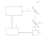
- FIG. 1 It is a block diagram which shows an example of the laser beam irradiation apparatus which concerns on this invention, and shows a schematic structure.
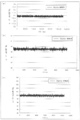
- (A), (b), and (c) show an example in which the output value of the laser beam is stabilized by the laser beam irradiation device, and the output fluctuation of the laser beam irradiated by the laser beam irradiation device is shown. It is a graph to show.
- (A), (b), (c) is a graph which shows the output fluctuation
- the output fluctuation of the laser beam irradiated by the laser beam irradiation apparatus according to the present invention is compared with the output fluctuation of the laser beam irradiated by the conventional laser beam irradiation apparatus. It is a graph.
- FIGS. 1 to 5 An embodiment of the present invention will be described with reference to FIGS. 1 to 5 as follows.
- cutting the film means not only dividing the film into at least two parts but also making a cut through the film and forming a groove (cut) having a predetermined depth in the film. "To cut at least part of” is also included. More specifically, “cutting” includes, for example, cutting (cutting off) an end portion of the film, half-cutting, marking processing, and the like.
- a laser beam irradiation apparatus 10 is an apparatus that irradiates a laser beam to the polarizing film in order to cut the polarizing film (film).
- a mirror 2 a beam splitter 3, a power sensor (measurement device) 4, a processing board (correction device) 5, and a condensing lens (not shown), and an optical member such as a beam expander (not shown) as necessary. It has more.
- the laser beam oscillator 1 is a member that oscillates a laser beam L.
- a CO 2 laser beam oscillator carbon dioxide laser beam oscillator
- a UV laser beam oscillator a UV laser beam oscillator
- a semiconductor laser beam oscillator a YAG laser beam oscillator
- An oscillator such as an excimer laser beam oscillator or the like can be used, but the specific configuration is not particularly limited.
- a CO 2 laser light oscillator is more preferable because it can oscillate laser light at a high output suitable for, for example, cutting processing of a polarizing film.
- a laser beam oscillator has a characteristic that the output of a laser beam is not constant, the output value fluctuates with a constant amplitude with a set value sandwiched in a very short period (for example, 1 millisecond), and the output is When it is low, the output value of the laser beam is likely to be unstable (the higher the output, the smaller the fluctuation range of the output value). For this reason, in order to further stabilize the output value of the laser beam oscillator 1, it is desirable to set the output of the laser beam oscillator 1 to a relatively high output.
- the output value of the laser beam oscillator 1 may be set in advance to an appropriate setting value according to conditions such as the material and thickness of the polarizing film. That is, the specific output value of the laser light oscillator 1 is an appropriate set value according to the material and thickness of the polarizing film, the conveyance speed of the polarizing film, and the ratio of transmitted light and reflected light by the beam splitter 3. It is desirable to set to.
- the frequency of the laser beam L to be irradiated may be appropriately set according to conditions such as the output of the laser beam oscillator 1, the material and thickness of the polarizing film, and the conveyance speed of the polarizing film, but is generally 5 kHz or more and 100 kHz or less. Can do.
- the laser light oscillator 1 outputs laser light in accordance with a preset setting value
- the processing board 5 that is a correction device corrects the output value so that the output value approaches the set value. ing.
- the laser light irradiation device 10 is more preferably provided with a beam expander on the optical path from the beam splitter 3 toward the polarizing film.
- the beam expander is a member that spreads the laser beam L1 into a parallel light beam, and a known beam expander can be used. Specifically, it is more preferable to widen the diameter of the laser beam L1 by, for example, about 2 to 10 times with a beam expander. By enlarging the diameter of the laser beam, the spot diameter of the laser beam irradiated on the polarizing film can be further reduced (reduced).
- the bend mirror 2 is a member that reflects the laser light L oscillated from the laser light oscillator 1 toward the beam splitter 3.
- the bend mirror 2 is preferably a plane reflecting mirror, for example, but may be any configuration that can reflect the laser light L toward the beam splitter 3. Moreover, the number is not specifically limited.
- the beam splitter 3 is a member that branches the laser light L oscillated from the laser light oscillator 1 and reflected by the bend mirror 2 into two parts at a certain ratio (ratio). That is, the beam splitter 3 is a member that branches the laser light L into the reflected light L1 and the transmitted light L2 at a constant ratio.
- the beam splitter 3 irradiates the polarized film with the reflected light L1 (one of the laser beams) out of the branched laser beam through an optical member such as a condenser lens, and is used for cutting the polarizing film.
- the transmitted light L2 (the other laser beam) is applied to the power sensor 4 to adjust the output of the laser beam oscillator 1.
- a known beam splitter can be used as the beam splitter 3.
- the condensing lens may be a known lens such as a spherical lens or an aspherical lens, and is not particularly limited.
- the cutting width (cutting distance) of the polarizing film is determined by the condensing diameter of the laser light that is the reflected light L1
- the condensing diameter of the laser light on the polarizing film is 5 ⁇ m or more and 500 ⁇ m or less. Preferably, it is 10 ⁇ m or more and 400 ⁇ m or less.
- the reflected light L1 is used for cutting the polarizing film
- the transmitted light L2 is used for adjusting the output of the laser beam oscillator 1
- the transmitted light L2 can be used for cutting the polarizing film
- the reflected light L1 can be used for adjusting the output of the laser light oscillator 1.
- a power sensor 4 as a measuring device is an element that converts the transmitted light L2 into a thermoelectromotive force and measures the intensity of the laser light that is the transmitted light L2. That is, the power sensor 4 measures the electric power generated when the laser beam is irradiated, and thereby measures the intensity of the laser beam.
- the measurement interval by the power sensor 4 is more preferably short, for example, 10 milliseconds, but is not particularly limited. Note that a known power sensor can be used as the power sensor 4.
- the measuring apparatus should just be the structure which can measure the intensity
- the power sensor 4 transmits the measured laser beam intensity (measured value) data to the processing board 5 via an A / D converter (not shown).
- the A / D converter converts analog data of measurement values into digital data, and transmits the digital data of measurement values to the processing board 5.
- the processing board 5 which is a correction device incorporates an arithmetic processing device such as a CPU (central processing unit).
- the processing board 5 is based on the measured value digital data received from the power sensor 4 via the A / D converter and the ratio (ratio) of the transmitted light L2 at the branching of the beam splitter 3.
- the output value of the laser beam oscillator 1 is calculated, and the output value of the laser beam oscillator 1 is judged to be large (over or short) with respect to a preset set value, and the output value of the laser beam oscillator 1 is corrected to full time so as to approach the set value. It has become.
- the processing board 5 feeds back the calculation result to the laser beam oscillator 1 in full time, specifically, for example, every 10 milliseconds, and the actual output value of the laser beam oscillator 1 approaches the set value. Adjustment (correction) is made as follows. More specifically, when the intensity of the laser beam that is the transmitted light L2 is small and the output value of the laser beam oscillator 1 is smaller than the set value, the laser is set so that the actual output value of the laser beam L is increased.
- the processing board 5 only needs to have a configuration capable of performing the above calculation and determination, and therefore the specific configuration is not limited to a specific configuration.
- the intensity of the transmitted light L2 is measured at a measurement interval of, for example, 10 milliseconds, and the output value of the laser beam L is adjusted by the power sensor 4 and the processing board 5 configured as described above. Since the so-called FTS (full time stabilizer) system is used to adjust (correct) the actual output value of the laser light oscillator 1 so as to approach the set value, the polarizing film can be cut appropriately. .
- FTS full time stabilizer
- the laser beam irradiation apparatus 10 is used as one apparatus constituting, for example, a slitter machine (not shown) that continuously cuts a polarizing film.
- the slitter machine in addition to the laser irradiation device 10, an unwinding unit for unwinding a long polarizing film (described later), a plurality of transport rolls for transporting the polarizing film, and a winding for winding the cut polarizing film A member such as a section is provided.
- the slitter machine will be described.
- the configuration other than the laser irradiation apparatus 10 in the slitter machine can employ a known configuration, the description thereof will be simplified.
- the unwinding part is a member that holds the long polarizing film and unwinds the polarizing film toward the transport roll by being rotated by a rotating device, and specifically includes a known unwinding part.
- tensile_strength added to a polarizing film and the conveyance speed of a polarizing film are adjusted with a rotating apparatus.
- one unwinding portion may be installed, but by installing two unwinding portions, before the polarizing film of one unwinding portion is completely unwound, the polarizing film is connected to the polarizing film of the other unwinding portion. Since it can connect, the time which replace
- a conveyance roll which conveys a polarizing film As a conveyance roll which conveys a polarizing film, a well-known conveyance roll is mentioned. Usually, the width of the transport roll is about 1.5 m to 2.5 m. Although the conveyance speed of a polarizing film should just be 1 m / sec or more and 100 m / sec or less, for example, it is not specifically limited. Moreover, the slitter machine may be provided with a touch roll that presses the polarizing film against the transport roll.
- Two winding units are installed, and are members that wind up a polarizing film that has been cut by being rotated by a rotating device. Specific examples include a known winding unit. The tension applied to the cut polarizing film and the conveying speed of the polarizing film are adjusted by a rotating device.
- the laser irradiation device 10 is disposed in the middle of a polarizing film transport path formed by a plurality of transport rolls, and continuously cuts the polarizing film transported by the transport rolls. In addition, you may perform the cutting process of a polarizing film, moving the laser irradiation apparatus 10 instead of moving a polarizing film.
- the polarizing film can be continuously cut by using the slitting machine having the above configuration.
- disconnects is not specifically limited, A well-known polarizing film can be mentioned.
- the polarizing film include a long polarizing film (for example, a polarizing film having a length of 10 m or more in the cutting direction), but a short film (for example, a polarizing film having a length of 2 m or more and less than 10 m in the cutting direction).
- the polarizing film of plate shape (For example, the length of the polarizing film in a cutting direction is 10 cm or more and less than 2 m) may be sufficient.
- the polarizing film has a film such as a TAC (triacetyl cellulose) film or a COP (cycloolefin polymer) film as a protective film member on both surfaces of the polarizer film, and a laser.
- a film such as a TAC (triacetyl cellulose) film or a COP (cycloolefin polymer) film as a protective film member on both surfaces of the polarizer film, and a laser.
- stacked through the adhesive on the TAC film of the reverse surface (back surface) with respect to the irradiation apparatus 10 can be mentioned.
- a polarizer film located in the center of a polarizing film the film by which the protective film members, such as TAC, were bonded to the film by which the polyvinyl alcohol film was dye
- hydrophilic polymer films such as partially formalized polyvinyl alcohol films, ethylene / vinyl acetate copolymer partially saponified films, and cellulose films, polyvinyl alcohol dehydrated products and polychlorinated
- a polyene oriented film such as a dehydrochlorinated product of vinyl can also be used.
- the protective film a film such as a polyester film or a polyethylene terephthalate film can also be used.
- the thickness and width of the protective film are not particularly limited, but from the viewpoint of being used as a protective film for a polarizing film, for example, the thickness is 5 ⁇ m or more and 60 ⁇ m or less, and the width is 200 mm or more and 1500 mm or less. It is preferable that
- the thickness of the polarizing film including the protective film is not particularly limited, but may be 100 ⁇ m or more and 500 ⁇ m or less. In addition, the thickness of the polarizer film is generally 10 ⁇ m or more and 50 ⁇ m or less. Furthermore, the polarizing film may further contain other layers in addition to the above three layers (polarizer film, TAC film and COP film, protective film) as long as there is no practical problem.
- the laser light irradiation method is a method of irradiating the polarizing film with a laser beam in order to cut the polarizing film (film), and two laser lights L oscillated from the laser light oscillator 1 are used.
- the reflected light L1 (one laser light) of the branched laser light is irradiated to the polarizing film through an optical member such as a condenser lens and used for cutting the polarizing film.
- the intensity of the laser light that is the transmitted light L2 (the other laser light) is measured, and the measured intensity (for example, digital data of the measured value) and the ratio (ratio) of the transmitted light L2 at the branching by the beam splitter 3
- the output value of the laser light oscillator 1 is calculated, and the magnitude (excess or deficiency) of the output value with respect to a preset set value is determined. So as to approach the output value to the set value is a method for full-time correction.
- the laser beam L a CO 2 laser beam is more preferable because a high output suitable for, for example, a cutting process of a polarizing film can be obtained.
- the frequency of the laser light L to be irradiated may be appropriately set depending on conditions such as the output of the laser light oscillator 1, the material and thickness of the polarizing film, and the conveying speed of the polarizing film, but is generally 5 kHz or more and 100 kHz or less. can do.
- the beam splitter 3 may be used as described above.
- the branching method is not limited to the method using the beam splitter, and any method can be used as long as the laser light L can be branched into two.
- the ratio between the reflected light L1 and the transmitted light L2 may be set to an appropriate setting value according to conditions such as the output of the laser light oscillator 1, the material and thickness of the polarizing film, the conveyance speed of the polarizing film, It is not particularly limited.
- the reflected light L1 is used for cutting the film and the transmitted light L2 is used for adjusting the output of the laser light oscillator 1.
- L2 may be used for cutting the film, and the reflected light L1 may be used for adjusting the output of the laser light oscillator 1.
- the power sensor 4 may be used as described above.
- the measuring method is not limited to the method using the power sensor, and any method that can measure the intensity of the laser beam may be used.
- the measurement interval is preferably shorter, for example, 10 milliseconds, but is not particularly limited.
- the processing board 5 may be used as described above.
- the correction method is not limited to the method using the processing board.
- the intensity of the measured laser beam for example, digital data of the measured value
- the ratio (ratio) of the transmitted light L2 and the preset settings
- the calculation result using the value is fed back to the laser beam oscillator 1 every 10 milliseconds, for example, and the actual output value of the laser beam oscillator 1 can be adjusted (corrected) so as to approach the set value. Any method can be used.
- the laser is set so that the actual output value of the laser beam L is increased.
- the output of the optical oscillator 1 is adjusted, while the intensity of the laser light that is the transmitted light L2 is large and the output value of the laser optical oscillator 1 is larger than the set value, the actual output value of the laser light L Any method can be used as long as the output of the laser beam oscillator 1 can be adjusted so as to be small.
- a so-called FTS (full time stabilizer) system that measures the intensity of the transmitted light L2 at a measurement interval of 10 milliseconds and adjusts the output value of the laser beam L is adopted. Since the actual output value of the laser beam oscillator 1 can be adjusted (corrected) so as to approach the set value, the polarizing film can be appropriately cut.
- the laser light irradiation method according to the present embodiment can be suitably used for, for example, a slitter machine that continuously performs a cutting process on a polarizing film.
- the laser beam irradiation apparatus and the laser beam irradiation method according to the present invention are an apparatus and a method that can appropriately cut a film, it can also be understood that they are a laser beam cutting apparatus and a laser beam cutting method. .
- the performance of the laser beam irradiation apparatus 10 according to this embodiment was examined. Moreover, in order to contrast with the performance of the laser beam irradiation apparatus 10 which concerns on this embodiment, the performance of the conventional laser beam irradiation apparatus was examined. Specifically, the output fluctuation of the laser beam L oscillated from the laser beam oscillator 1 of the laser beam irradiation apparatus 10 according to the present embodiment and the conventional laser beam irradiation apparatus was measured.
- Fig. 3 shows the configuration of the laser beam irradiation device whose performance was examined.
- the conventional laser beam irradiation apparatus 20 includes a laser beam oscillator 1, a bend mirror 2, a bend mirror 8, and a condenser lens (not shown). That is, the conventional laser beam irradiation apparatus 20 does not include a beam splitter, a power sensor, an A / D converter, and a processing board, and all of the laser beam L oscillated from the laser beam oscillator 1 is sent to the bend mirror 2 and the bend. The light is reflected by the mirror 8 and used for cutting the film.
- the laser beam irradiation apparatus 20 has a configuration (for example, an optical member such as a beam expander) other than the configuration for correcting the output value of the laser beam oscillator 1 to be close to a set value.
- the laser beam oscillator 1 used the same oscillator by the laser beam irradiation apparatus 10 and the laser beam irradiation apparatus 20.
- the output fluctuation of the laser beam L oscillated from the laser beam oscillator 1 was measured using the laser beam irradiation device 10 according to the present embodiment and the conventional laser beam irradiation device 20.
- the output value of the laser beam L oscillated from the laser beam oscillator 1 was set to 14.0 W, and the film was cut at a speed of 6 m / min.
- the output value of the actually output laser beam L is generally within the range of 13.4 to 14.1 W (average). 13.8W, runout width 0.7W).
- the output value of the actually output laser beam L varies within a range of 12.3 to 15.0 W in general. (Average 13.8W, runout 2.7W). Therefore, as is apparent from the result shown in FIG.
- the laser beam L oscillated from the laser beam oscillator 1 of the laser beam irradiation apparatus 10.
- the output fluctuation of the laser beam irradiation apparatus 10 according to the present embodiment was small, and it was found that the performance of the laser beam irradiation apparatus 10 according to the present embodiment was remarkably superior to that of the conventional laser beam irradiation apparatus 20.
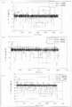
- the output value of the laser beam L oscillated from the laser beam oscillator 1 was set to 49.5 W, and the film was cut at a speed of 30 m / min.
- the output value of the actually output laser beam L is generally within the range of 48.9 to 50.4 W (average). 49.5W, runout width 1.6W).
- the output value of the actually output laser beam L generally varies within the range of 46.4 to 51.1W. (Average 49.2W, runout 4.7W). Therefore, as is apparent from the result shown in FIG.
- the output value of the laser beam L oscillated from the laser beam oscillator 1 was set to 100.0 W, and the film was cut at a speed of 60 m / min.
- the output value of the actually output laser beam L is generally within the range of 99.3 to 100.6 W (average) 99.9W, runout width 1.3W).
- the output value of the actually output laser beam L generally varies within the range of 95.2 to 102.8W. (Average 99.1W, runout 7.6W). Therefore, as is apparent from the result shown in FIG.
- the performance of the laser light irradiation apparatus 10 according to the present embodiment is higher than that of the conventional laser light irradiation apparatus 20 from the laser light oscillator 1. Since the output fluctuation of the oscillated laser beam L is small, it is clear that it is remarkably excellent.
- the laser beam irradiation apparatus and the laser beam irradiation method according to the present invention even if the output value of the laser beam is set to a value necessary (and lower) for cutting the film, output fluctuation is suppressed. Therefore, the output value does not become lower than a certain value (smaller) than the set value, and the film can be cut appropriately. Therefore, it is possible to provide a laser light irradiation apparatus and a laser light irradiation method capable of suppressing output fluctuation (fluctuation with respect to a set value), stabilizing the output of the laser light to be irradiated, and appropriately cutting the film. There is an effect.
- the laser light irradiation apparatus and laser light irradiation method according to the present invention can be used for, for example, cutting processing of a polarizing film, so in the manufacturing process of various products such as a liquid crystal panel using the polarizing film, That is, it can be widely used in various industries using a polarizing film.
- Laser oscillator 2 Bend mirror 3 Beam splitter 4 Power sensor (measuring device) 5 processing board (correction device) 10 Laser light irradiation device L Laser light L1 Reflected light (laser light) L2 Transmitted light (laser light)
Landscapes
- Engineering & Computer Science (AREA)
- Physics & Mathematics (AREA)
- Optics & Photonics (AREA)
- Mechanical Engineering (AREA)
- Plasma & Fusion (AREA)
- Health & Medical Sciences (AREA)
- Manufacturing & Machinery (AREA)
- Ophthalmology & Optometry (AREA)
- Laser Beam Processing (AREA)
- Polarising Elements (AREA)
Priority Applications (2)
| Application Number | Priority Date | Filing Date | Title |
|---|---|---|---|
| CN2011800616215A CN103260816A (zh) | 2010-12-24 | 2011-12-22 | 激光照射装置及激光照射方法 |
| KR1020137018981A KR20140019313A (ko) | 2010-12-24 | 2011-12-22 | 레이저광 조사 장치 및 레이저광 조사 방법 |
Applications Claiming Priority (2)
| Application Number | Priority Date | Filing Date | Title |
|---|---|---|---|
| JP2010288671A JP2012135782A (ja) | 2010-12-24 | 2010-12-24 | レーザー光照射装置およびレーザー光照射方法 |
| JP2010-288671 | 2010-12-24 |
Publications (1)
| Publication Number | Publication Date |
|---|---|
| WO2012086764A1 true WO2012086764A1 (ja) | 2012-06-28 |
Family
ID=46314031
Family Applications (1)
| Application Number | Title | Priority Date | Filing Date |
|---|---|---|---|
| PCT/JP2011/079832 Ceased WO2012086764A1 (ja) | 2010-12-24 | 2011-12-22 | レーザー光照射装置およびレーザー光照射方法 |
Country Status (5)
| Country | Link |
|---|---|
| JP (1) | JP2012135782A (enExample) |
| KR (1) | KR20140019313A (enExample) |
| CN (1) | CN103260816A (enExample) |
| TW (1) | TW201233482A (enExample) |
| WO (1) | WO2012086764A1 (enExample) |
Families Citing this family (3)
| Publication number | Priority date | Publication date | Assignee | Title |
|---|---|---|---|---|
| JP2013128966A (ja) * | 2011-12-22 | 2013-07-04 | Sumitomo Chemical Co Ltd | レーザー光照射装置、フィルム切断装置、レーザー光照射方法及びフィルム切断方法 |
| JP6342949B2 (ja) | 2016-05-17 | 2018-06-13 | ファナック株式会社 | 反射光を抑制しながらレーザ加工を行うレーザ加工装置及びレーザ加工方法 |
| JP7475220B2 (ja) * | 2020-07-03 | 2024-04-26 | 住友重機械工業株式会社 | レーザパワー計測装置 |
Citations (2)
| Publication number | Priority date | Publication date | Assignee | Title |
|---|---|---|---|---|
| JPS6478694A (en) * | 1987-09-19 | 1989-03-24 | Hitachi Maxell | Method and device for cutting raw film consisting of plastic film as base material |
| JPH09122946A (ja) * | 1995-10-31 | 1997-05-13 | Hitachi Cable Ltd | 炭酸ガスレーザ光を用いた基板の加工方法およびその加工装置 |
Family Cites Families (2)
| Publication number | Priority date | Publication date | Assignee | Title |
|---|---|---|---|---|
| JP2000357835A (ja) * | 1999-06-15 | 2000-12-26 | Amada Eng Center Co Ltd | レーザ発振器 |
| JP4274251B2 (ja) * | 2007-01-24 | 2009-06-03 | ソニー株式会社 | レーザ描画方法及びレーザ描画装置 |
-
2010
- 2010-12-24 JP JP2010288671A patent/JP2012135782A/ja not_active Withdrawn
-
2011
- 2011-12-20 TW TW100147292A patent/TW201233482A/zh unknown
- 2011-12-22 KR KR1020137018981A patent/KR20140019313A/ko not_active Withdrawn
- 2011-12-22 CN CN2011800616215A patent/CN103260816A/zh active Pending
- 2011-12-22 WO PCT/JP2011/079832 patent/WO2012086764A1/ja not_active Ceased
Patent Citations (2)
| Publication number | Priority date | Publication date | Assignee | Title |
|---|---|---|---|---|
| JPS6478694A (en) * | 1987-09-19 | 1989-03-24 | Hitachi Maxell | Method and device for cutting raw film consisting of plastic film as base material |
| JPH09122946A (ja) * | 1995-10-31 | 1997-05-13 | Hitachi Cable Ltd | 炭酸ガスレーザ光を用いた基板の加工方法およびその加工装置 |
Also Published As
| Publication number | Publication date |
|---|---|
| TW201233482A (en) | 2012-08-16 |
| JP2012135782A (ja) | 2012-07-19 |
| CN103260816A (zh) | 2013-08-21 |
| KR20140019313A (ko) | 2014-02-14 |
Similar Documents
| Publication | Publication Date | Title |
|---|---|---|
| KR101706416B1 (ko) | 편광판 절단 방법 및 상기 방법에 의해 절단된 편광판 | |
| JP6381539B2 (ja) | 異なる幅のガラスリボンを製造するための方法及び装置 | |
| JP5293498B2 (ja) | ウエブ搬送装置及びその方法と電池の製造方法 | |
| KR20150096691A (ko) | 광학 표시 디바이스의 생산 방법 및 광학 표시 디바이스의 생산 시스템 | |
| CN109073805B (zh) | 用于在光学膜处进行标记的系统和方法 | |
| US10710351B2 (en) | System and method for continuously manufacturing optical display device | |
| TW201628751A (zh) | 彈性玻璃基板之回饋控制的雷射切割 | |
| KR101465908B1 (ko) | 액정 패널의 제조 방법 및 제조 시스템 | |
| WO2012086764A1 (ja) | レーザー光照射装置およびレーザー光照射方法 | |
| CN103153526B (zh) | 激光切割装置及具有该装置的切条机 | |
| JP2014121736A (ja) | レーザー光照射装置およびレーザー光照射方法 | |
| WO2013094758A1 (ja) | レーザー光照射システム、レーザー光照射方法及び記録媒体 | |
| US7955466B2 (en) | Method of and apparatus for manufacturing polarization plate | |
| JP6020884B2 (ja) | レーザー加工方法 | |
| JP4614175B2 (ja) | フィルム貼り合わせ装置 | |
| KR102801673B1 (ko) | 필름용 슬리팅 장치 | |
| JPH05192705A (ja) | ストリップ圧延の平担度制御装置 | |
| WO2024157622A1 (ja) | 粘着剤層を有する積層フィルムの製造方法 | |
| KR20220093279A (ko) | 필름 롤의 제조 시스템 및 필름 롤의 제조 방법 |
Legal Events
| Date | Code | Title | Description |
|---|---|---|---|
| 121 | Ep: the epo has been informed by wipo that ep was designated in this application |
Ref document number: 11851832 Country of ref document: EP Kind code of ref document: A1 |
|
| NENP | Non-entry into the national phase |
Ref country code: DE |
|
| ENP | Entry into the national phase |
Ref document number: 20137018981 Country of ref document: KR Kind code of ref document: A |
|
| 122 | Ep: pct application non-entry in european phase |
Ref document number: 11851832 Country of ref document: EP Kind code of ref document: A1 |