WO2012086367A1 - シール貼付治具 - Google Patents
シール貼付治具 Download PDFInfo
- Publication number
- WO2012086367A1 WO2012086367A1 PCT/JP2011/077307 JP2011077307W WO2012086367A1 WO 2012086367 A1 WO2012086367 A1 WO 2012086367A1 JP 2011077307 W JP2011077307 W JP 2011077307W WO 2012086367 A1 WO2012086367 A1 WO 2012086367A1
- Authority
- WO
- WIPO (PCT)
- Prior art keywords
- sticking
- seal
- sticker
- jig
- target range
- Prior art date
- Legal status (The legal status is an assumption and is not a legal conclusion. Google has not performed a legal analysis and makes no representation as to the accuracy of the status listed.)
- Ceased
Links
Images

Classifications
-
- B—PERFORMING OPERATIONS; TRANSPORTING
- B65—CONVEYING; PACKING; STORING; HANDLING THIN OR FILAMENTARY MATERIAL
- B65C—LABELLING OR TAGGING MACHINES, APPARATUS, OR PROCESSES
- B65C11/00—Manually-controlled or manually-operable label dispensers, e.g. modified for the application of labels to articles
Definitions
- the present invention relates to a sticker sticking jig.
- Patent Document 1 a metal thin and thin bifurcated plate sticking jig having two spatula tips, one of the tips perpendicular to the spatula surface A jig having a configuration including a vertical portion has been proposed.
- the jig shown in Patent Document 1 is on the extension line of the tweezers, and the bifurcated metal jig performs the seal alignment by the vertical portion at the tip.
- the configuration of the tip portion for alignment as described above has a problem that there is a high possibility of interference with these uneven portions.
- the sticking position of the sticker is deep in correspondence with the recessed part, the tweezers or the forked structure itself interferes with the periphery of the sticking position of the sticker, so that the sticking target is unnecessary so as to expose the sticking position of the sticker.
- the object of the present invention is to provide a seal sticking jig capable of easily sticking a seal to a designated position even at a sticking position of a complicated shape.
- the seal sticking jig of the present invention is a seal sticking jig for sticking a seal to a member having irregularities formed around the sticking target range of the seal, the sticking position being within the designated sticking target range and A distal end surface having substantially the same shape as the pasting target range is provided, and the distal end surface is a contact surface with the seal.
- the seal sticking jig may form a gap having a thickness about the thickness of the seal between the central portions when the peripheral portions facing each other on the tip end surface and the sticking target range are in contact with each other.
- tool is a shape where the front-end
- a sticking object is a part of the model member, and the seal sticking jig is formed in a portion having no role of the model member.
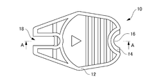
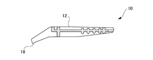
- FIG. 5 is a cross-sectional view taken along line A-A ′ of FIG. 4. It is a front view of a sticker sticking jig. It is a perspective view which shows the condition which applies a seal sticking jig
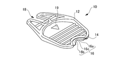
- FIG. 1 is a perspective view of a sticking jig according to an embodiment of the present invention
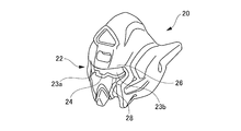
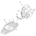
- FIG. 2 is a perspective view of a sticking object for which the sticking jig of FIG. 1 is designated for use
- FIG. 3 is designated for a sticking object of FIG. It is a front view of the sticker stuck on the sticking object range.
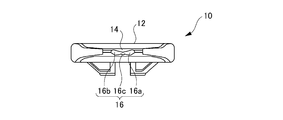
- the seal sticking jig 10 of the present embodiment includes a holding part 12 and a tip part 14, and the tip part 14 is provided with a tip surface 16.
- the distal end portion 14 and the distal end surface 16 are configured as a dedicated jig used when the seal 30 shown in FIG. 3 is attached to the designated position 22 to be attached shown in FIG.
- the sticking target is the head 20 of the doll robot toy, and the sticking target range 22 with respect to the seal 30 is a range occupied by the eyes 23a and 23b and the nose root 24.
- a brow mountain portion 26 and a cheek portion 28 protruding from the surface of the pasting target range 22 are provided around the pasting target range 22, and the pasting target range 22 is recessed from the brow mountain portion 26 and the cheek portion 28.
- the seal 30 includes both end portions 32 a and 32 b corresponding to the eye portions 23 a and 23 b of the head 20 of the doll robot toy, and a central portion 34 corresponding to the nasal root portion 24. And it is designated to be pasted over the entire range of the pasting target range 22.
- the distal end surface 16 and the distal end portion 14 following the distal end surface 16 are configured exclusively for the pasting target range 22 and the surrounding shape.
- the front end surface 16 abuts on the sticker 30 and presses the sticker 30 to the sticking position.
- the distal end surface 16 is formed with curved distal end surfaces 16 a and 16 b corresponding to the eye portions 23 a and 23 b and the nasal root portion 24 of the application target range 22. Furthermore, within the area range of the pasting target range 22, substantially the same shape as that is applied.
- the curved configuration of the distal end surface 16 is such that the thickness of the seal 30 is between the nose root portion 24 and the distal end surface 16c when the edge portions of the eye portions 23a and 23b facing the distal end surfaces 16a and 16b abut. The gap is formed.
- the tip portion 14 is a protruding portion that protrudes from the holding portion 12 with a length that is at least equal to the depth of the recessed pasting target range 22.
- the tip portion 14 that is the protruding portion is suppressed to a thickness equivalent to the width of the tip surface 16. Therefore, the seal sticking jig 10 does not interfere with the eyebrow mountain portion 26 and the cheek portion 28 when the seal 30 is attached.
- the distal end portion 14 only needs to have a shape that does not interfere with the portion surrounding the designated pasting target range 22, and corresponds to the shape of the portion surrounding the pasting target range 22 (such as the brow mountain portion 26 and the cheek portion 28). It is configured appropriately. Since it is a pasting target designated in advance, its shape is also known, and interference can be completely avoided by configuring along the shape.
- the tip surface of the sticking jig is provided with a shape exclusively for the seal that fits in the sticking target range with respect to the seal designated as the sticking target range, so that the tip surface has the sticking target range. Without interfering with the surrounding portion, the seal can be surely pressed against the application target range.
- the seal sticking jig 10 of the present embodiment uses a portion (rear end portion) that has no role in the model member separating jig used when separating the component from the runner. That is, in other words, a claw portion 18 for separating a model member is provided on the opposite side of the distal end surface 16 and the distal end portion 14 with the holding portion 12 as the center. These are used on each side as needed. Since the claw portion 18 is not required after the model member is separated, the claw portion 18 becomes a jig to which a new role is given according to the present embodiment.
- model member separation jig of the present embodiment in addition to the model member separation jig of the present embodiment, it can be applied to a member having a part having no role, and in the case of a model like this case, a runner, a product plate, a battery lid, a part Applicable to some areas.
- the sticker 30 in sticking the seal 30 to the pasting target range 22, the sticker 30 is pushed into the pasting target range 22 at the back position by the tip 14 of the sticking jig 10. .
- the seal sticking jig 10 is provided with upper and lower marks 19 to designate the vertical direction. While finely adjusting the alignment of the seal 30 while keeping the distance between the distal end surface 16 and the application target range 22 equal, the seal 30 is pushed in and the seal 30 is applied to the application target range 22.
- the end portion 32a of the seal 30 can be sandwiched between the eye portion 23a and the distal end surface 16a. At this time, the alignment of the end portion 32a is substantially completed. Next, the end portion 32b side is gradually brought closer to the eye portion 23b by the distal end surface 16b. During this approach, it is possible to continue fine adjustment of the end 32b and push it toward the eye 23b.
- the curved configuration of the distal end surface 16 is such that the seal 30 is provided between the nose root portion 24 and the distal end surface 16c when the respective edge portions of the eye portions 23a and 23b facing the distal end surfaces 16a and 16b abut. It is formed so that a gap of about the thickness of can be made. Accordingly, the seal 30 can be positioned from both end portions 32a and 32b, and the central portion 34 is pasted after the positions of both end portions 32a and 32b are determined, so that the seal 30 can be pasted to the pasting target range 22 accurately and easily. it can.
- the dedicated seal sticking jig 10 for the sticking target range 22 designated in advance is given the most suitable form for work, simplifying work and performing accurate sticking. And the size can be kept to a minimum. In addition, it is possible to deal with a pasting target range at a deep position, and there is no need to divide the parts at unnecessary positions.
- the present invention is not limited to the above-described embodiment, but includes modifications and improvements as long as the object of the present invention can be achieved.
- the range occupied by the head 20 of the doll robot toy, in particular, the eye portions 23a and 23b and the nose root portion 24 is the range to be applied, but is not limited to such a location.
- the present invention can be applied to any portion where a dedicated sticker sticking jig is required, and is particularly effective for a deep portion where irregularities are formed around the seal sticking target range or a portion that is difficult to use with tweezers.
Landscapes
- Toys (AREA)
- Labeling Devices (AREA)
Abstract
【課題】複雑な形状のシール貼付位置であっても、指定位置に容易にシールを貼付することができるシール貼付治具を提供する。 【解決手段】貼付位置を指定されたシール30の貼付対象範囲22に収まりかつその貼付対象範囲22と略同形状を有する先端面16を備え、先端面16がシール30との当接面となるシール貼付治具。先端面16と貼付対象範囲22との相対する周辺部同士の接触時に中央部同士がシール30の厚さ程度の隙間を形成する。
Description
本発明は、シール貼付治具に関する。
従来、シール貼付の際に使用する工具としては、ピンセットの利用が一般的に用いられている。その中で、金属製の細長く薄い二股の板状物のシール貼り付け治具であって、へら状の二つの先端部を有し、先端部の一方が、へら状の面に対して垂直の垂直部を備える構成の治具を提案されている(特許文献1)。
特許文献1に示す治具は、ピンセットの延長線上にあり、二股の金属製治具は、その先端部の垂直部によってシールの位置合わせを実施している。ここで、模型玩具などにおいては、シール貼付位置の周辺には凹凸形状の部位が配置されていることは珍しくない。従って、上記のように位置合わせの為の先端部の構成は、これらの凹凸形状の部位と干渉する可能性が大きいという問題があった。特に、シール貼付位置が窪み部分に対応し奥まっている場合には、ピンセットや二股の構成自体がシール貼付位置の周辺に干渉することから、シール貼付位置を露出させるように、貼付対象を不要な位置で分割する場合もあるという問題もあった。
そこで、プラモデル等の模型玩具の作成においては、シール貼付位置の周辺に凹凸が形成されないパーツを作成し、そのパーツにシールを貼付した後、他の装飾パーツ等を取り付けて立体的に仕上げていく必要があり、工程が複雑になり、大変手間のかかるものであった。また、シールを貼付しやすい形状にするため、シール貼付位置の周辺に凹凸を形成しないよう、不要な箇所であってもパーツを分割する必要があり、外観的にも見栄えが悪くなることがあった。
本発明は、複雑な形状のシール貼付位置であっても、指定位置に容易にシールを貼付することができるシール貼付治具を提供することを目的とする。
本発明のシール貼付治具は、シールの貼付対象範囲の周辺に凹凸が形成された部材にシールを貼付するシール貼付治具であって、貼付位置を指定されたシールの貼付対象範囲に収まりかつその貼付対象範囲と略同形状を有する先端面を備え、前記先端面が前記シールとの当接面となる。
また、本発明のシール貼付治具において、シール貼付治具は、先端面と貼付対象範囲上との相対する周辺部同士の接触時に中央部同士がシールの厚さ程度の隙間を形成することが好ましい。また、シール貼付治具は、先端面に続く先端部が、指定された貼付対象範囲を囲む部分に干渉しない形状であることが好ましい。また、貼付対象が模型用部材の一部であり、シール貼付治具は、模型用部材の役割のない部分に形成されることが好ましい。
本発明によれば、複雑な形状のシール貼付位置に容易にシールを貼付することができるシール貼付治具を提供することが可能となる。
以下、本発明に係わるシール貼付治具の実施形態について、図面を参照しながら説明する。図1は本発明の実施形態に係わるシール貼付治具の斜視図、図2は図1のシール貼付治具が使用指定される貼付対象の斜視図、図3は図2の貼付対象の指定された貼付対象範囲に貼付されるシールの正面図である。
本実施形態のシール貼付治具10は、保持部12と、先端部14とから構成され、先端部14には先端面16が備えられる。この先端部14及び先端面16は、図2に示した貼付対象の指定位置22に図3で示したシール30を貼り付ける際に使用する専用治具として構成されている。
貼付対象は、人形ロボット玩具の頭部20であり、シール30に対する貼付対象範囲22は、眼部23a、23b及び鼻根部24で占められる範囲である。本実施の形態では、貼付対象範囲22の周囲には、貼付対象範囲22の表面より突出した眉山部26及び頬部28が設けられ、貼付対象範囲22は眉山部26及び頬部28からは奥まって形成されている。シール30は、人形ロボット玩具の頭部20の眼部23a、23bに対応する両端部32a、32bと、鼻根部24に対応する中央部34から構成される。そして、貼付対象範囲22の奥まった範囲全域に渡って貼り付けられるよう指定されている。
先端面16とその先端面16に続く先端部14は、貼付対象範囲22とその回りの形状に対応して専用で構成される。先端面16は、シール30貼付の際には、シール30に当接して、貼付位置へシール30を押しつける。
図1、図4、図5、図6で示すように、先端面16は、貼付対象範囲22の眼部23a、23b及び鼻根部24に対応して湾曲した先端面16a、16bを形成され、更に貼付対象範囲22の面積範囲内で、その形状と略同形状を適用されている。先端面16の湾曲構成は、先端面16a、16bと相対する眼部23a、23bのそれぞれの縁部分が当接する場合に、鼻根部24と先端面16cとの間にシール30の厚さ程度の隙間ができるように形成されている。
先端部14は、奥まった貼付対象範囲22の深さと少なくとも同等の長さで保持部12から突出する突出部分である。この突出部分である先端部14は、先端面16の幅と同等程度の厚みに抑えられている。従って、シール30を貼り付ける際に、眉山部26及び頬部28にシール貼付治具10が干渉することはない構成である。
このように、先端部14は、指定された貼付対象範囲22を囲む部分に干渉しない形状であればよく、貼付対象範囲22を囲む部分の形状(眉山部26及び頬部28など)に対応して、適宜に構成される。予め指定された貼付対象であるので、その形状も解っており、その形状に沿って構成することで、干渉を完全に避けることが可能である。本実施の形態において、シール貼付治具の先端面は、貼付対象範囲に指定されたシールに対して、その貼付対象範囲に収まるこのシール専用の形状を備えることにより、先端面が貼付対象範囲を囲む部分と干渉することなく、シールを貼付対象範囲に確実に押しつけることができる。
本実施形態のシール貼付治具10は、ランナーから部品を分離する時に用いる模型用部材分離治具での役割のない部分(後端部分)を使用している。つまり、逆に述べれば、保持部12を中心に、先端面16と先端部14の反対側には模型用部材分離用の爪部18が備えられている。これらはそれぞれの側が必要に応じ使用される。この爪部18は模型用部材分離後には、不要となるため、本実施形態により新たな役割を与えられる治具となる。本発明では、本実施形態の模型用部材分離治具以外にも、役割のない部分がある部材には適用可能であり、本件のような模型の場合、ランナー、製品プレート、電池蓋、パーツの一部などに適用可能である。
図7に示すように、貼付対象範囲22へのシール30の貼り付けにおいて、奥まった位置にある貼付対象範囲22に対して、シール貼付治具10の先端部14によりシール30を押し込む状態となる。シール貼付治具10には上下の目印19が配置され、上下方向を指定している。先端面16と貼付対象範囲22との距離を均等に保ったまま、シール30の位置合わせの微調節を行いつつ、シール30を押し込み、貼付対象範囲22にシール30を貼り付ける。
位置合わせの微調整についての他の手順として、まず、シール30の端部32aを眼部23aと先端面16aとで挟持することも可能である。この時、端部32aの位置合わせは略完了することとなる。次に、端部32b側を先端面16bにより眼部23bへ徐々に近づける。この近づける間に、端部32bの微調整を続け、眼部23b側へ押し込むことも可能である。
いずれにしても、先端面16の湾曲構成は、先端面16a、16bと相対する眼部23a、23bのそれぞれの縁部分が当接する場合に、鼻根部24と先端面16cとの間にシール30の厚さ程度の隙間ができるように形成されている。従って、シール30の両端部32a、32bから位置決めでき、中央部34は両端部32a、32bの位置が決まってから貼り付くこととなり、シール30を貼付対象範囲22へ正確かつ容易に貼り付けることができる。
本実施形態によれば、予め指定された貼付対象範囲22に対する専用のシール貼付治具10とすることで、作業にもっとも適した形態を与えて、作業の簡素化と、正確な貼り付けを実施することができ、大きさも最小限に止めることができる。また、奥まった位置の貼付対象範囲にも対応でき、部品を不要な位置で分割するような必要も無い。
なお、本発明は上記実施形態に限定されるものではなく、本発明の目的を達成できる範囲での変形、改良などは本発明の含まれるものである。例えば、本実施形態は、人形ロボット玩具の頭部20、特に、眼部23a、23b及び鼻根部24で占められる範囲が貼付対象範囲であるが、このような箇所に限定されることはない。専用のシール貼付治具が求められる部分であれば、適用可能であり、特に、シール貼付対象範囲の周囲に凹凸が形成された奥まった部分や、ピンセットなどでは困難が伴う部分に有効である。
10 シール貼付治具
12 保持部
14 先端部
16a、16b 先端面
19 目印
20 人形ロボット玩具の頭部
22 貼付対象範囲
23a、23b 眼部
24 鼻根部
30 シール
32a、32b 両端部
34 中央部
12 保持部
14 先端部
16a、16b 先端面
19 目印
20 人形ロボット玩具の頭部
22 貼付対象範囲
23a、23b 眼部
24 鼻根部
30 シール
32a、32b 両端部
34 中央部
Claims (4)
- シールの貼付対象範囲の周辺に凹凸が形成された部材にシールを貼付するシール貼付治具であって、
貼付位置を指定されたシールの前記貼付対象範囲に収まりかつその貼付対象範囲と略同形状を有する先端面を備え、前記先端面が前記シールとの当接面となるシール貼付治具。 - 請求項1において、
前記先端面と前記貼付対象範囲上との相対する周辺部同士の接触時に中央部同士が前記シールの厚さ程度の隙間を形成するシール貼付治具。 - 請求項1または請求項2において、
前記先端面に続く先端部が、指定された前記貼付対象範囲を囲む部分に干渉しない形状であるシール貼付治具。 - 請求項1乃至請求項3のいずれか一項において、
貼付対象は模型用部材の一部であり、前記シール貼付治具は、前記模型用部材の役割のない部分に形成されるシール貼付治具。
Applications Claiming Priority (2)
| Application Number | Priority Date | Filing Date | Title |
|---|---|---|---|
| JP2010-284934 | 2010-12-21 | ||
| JP2010284934A JP5358555B2 (ja) | 2010-12-21 | 2010-12-21 | シール貼付治具 |
Publications (1)
| Publication Number | Publication Date |
|---|---|
| WO2012086367A1 true WO2012086367A1 (ja) | 2012-06-28 |
Family
ID=46313649
Family Applications (1)
| Application Number | Title | Priority Date | Filing Date |
|---|---|---|---|
| PCT/JP2011/077307 Ceased WO2012086367A1 (ja) | 2010-12-21 | 2011-11-28 | シール貼付治具 |
Country Status (3)
| Country | Link |
|---|---|
| JP (1) | JP5358555B2 (ja) |
| CN (1) | CN102530340A (ja) |
| WO (1) | WO2012086367A1 (ja) |
Families Citing this family (2)
| Publication number | Priority date | Publication date | Assignee | Title |
|---|---|---|---|---|
| JP2014097217A (ja) * | 2012-11-15 | 2014-05-29 | Kuwagata:Kk | 成形物 |
| JP7571324B1 (ja) | 2024-03-11 | 2024-10-22 | 株式会社バンダイ | 模型部品 |
Citations (9)
| Publication number | Priority date | Publication date | Assignee | Title |
|---|---|---|---|---|
| JPH0468765U (ja) * | 1990-10-19 | 1992-06-18 | ||
| JP2706842B2 (ja) * | 1990-09-07 | 1998-01-28 | 三和産業株式会社 | ロータリー式圧送機 |
| JPH11324590A (ja) * | 1998-05-14 | 1999-11-26 | Shimizu Corp | セグメント用の防水シール貼付治具 |
| JP2001239525A (ja) * | 2000-03-01 | 2001-09-04 | Kojima Press Co Ltd | 樹脂成形品の部分加飾用金型及び加飾方法 |
| JP3383343B2 (ja) * | 1993-04-05 | 2003-03-04 | ミネソタ マイニング アンド マニュファクチャリング カンパニー | 粘着テープ貼付治具 |
| JP2003095230A (ja) * | 2001-09-20 | 2003-04-03 | Sony Corp | フィルム貼付方法及びその装置 |
| JP2009037815A (ja) * | 2007-08-01 | 2009-02-19 | Toyota Motor Corp | 電池封止方法、電池封止用治具、および、電池の製造方法 |
| JP2009131351A (ja) * | 2007-11-29 | 2009-06-18 | Toppan Printing Co Ltd | レンズ付き封印シールカバー、回路ボックスおよび封印シール |
| JP3157588U (ja) * | 2009-11-04 | 2010-02-25 | 株式会社バンダイ | 模型部品分離治具及び模型用樹脂成形部品 |
Family Cites Families (2)
| Publication number | Priority date | Publication date | Assignee | Title |
|---|---|---|---|---|
| JP2706824B2 (ja) * | 1989-05-24 | 1998-01-28 | 株式会社倉本産業 | ラベル類の貼着方法と装置 |
| CN2315049Y (zh) * | 1997-11-27 | 1999-04-21 | 姜丹 | 光盘片标签粘贴机 |
-
2010
- 2010-12-21 JP JP2010284934A patent/JP5358555B2/ja active Active
-
2011
- 2011-11-28 WO PCT/JP2011/077307 patent/WO2012086367A1/ja not_active Ceased
- 2011-12-16 CN CN2011104333594A patent/CN102530340A/zh active Pending
Patent Citations (9)
| Publication number | Priority date | Publication date | Assignee | Title |
|---|---|---|---|---|
| JP2706842B2 (ja) * | 1990-09-07 | 1998-01-28 | 三和産業株式会社 | ロータリー式圧送機 |
| JPH0468765U (ja) * | 1990-10-19 | 1992-06-18 | ||
| JP3383343B2 (ja) * | 1993-04-05 | 2003-03-04 | ミネソタ マイニング アンド マニュファクチャリング カンパニー | 粘着テープ貼付治具 |
| JPH11324590A (ja) * | 1998-05-14 | 1999-11-26 | Shimizu Corp | セグメント用の防水シール貼付治具 |
| JP2001239525A (ja) * | 2000-03-01 | 2001-09-04 | Kojima Press Co Ltd | 樹脂成形品の部分加飾用金型及び加飾方法 |
| JP2003095230A (ja) * | 2001-09-20 | 2003-04-03 | Sony Corp | フィルム貼付方法及びその装置 |
| JP2009037815A (ja) * | 2007-08-01 | 2009-02-19 | Toyota Motor Corp | 電池封止方法、電池封止用治具、および、電池の製造方法 |
| JP2009131351A (ja) * | 2007-11-29 | 2009-06-18 | Toppan Printing Co Ltd | レンズ付き封印シールカバー、回路ボックスおよび封印シール |
| JP3157588U (ja) * | 2009-11-04 | 2010-02-25 | 株式会社バンダイ | 模型部品分離治具及び模型用樹脂成形部品 |
Also Published As
| Publication number | Publication date |
|---|---|
| JP2012131529A (ja) | 2012-07-12 |
| JP5358555B2 (ja) | 2013-12-04 |
| CN102530340A (zh) | 2012-07-04 |
Similar Documents
| Publication | Publication Date | Title |
|---|---|---|
| JP4771234B2 (ja) | 挟み具 | |
| US20150374101A1 (en) | Eyeliner stencil and eyeliner application method therefor | |
| CA2969984A1 (en) | Eyelash extensions support device | |
| JP2014108878A (ja) | 多関節型ロボットによるフィルム剥離方法およびその剥離方法を用いた多関節型ロボットによるワーク装着方法 | |
| JP5358555B2 (ja) | シール貼付治具 | |
| GB2588321A (en) | A bead for a frame member | |
| CA2471913A1 (en) | Surgical tool | |
| CN103038039A (zh) | 刮板式去毛刺装置 | |
| WO2013021693A1 (ja) | 爪切り | |
| WO2008149634A1 (ja) | 打ち込み工具のノーズアダプタ | |
| HK1193923A2 (en) | Eyelash curler and attachment for eyelash curler | |
| CN207326803U (zh) | 翼子板标识定位工装和便于手持的定位工装 | |
| TW200714932A (en) | Prism assembly and method for forming air gap therebetween | |
| JP2004236969A (ja) | 眉線修正補助具 | |
| US20180194022A1 (en) | Manual cutting tool | |
| JP4108296B2 (ja) | ゴム部品の貼着治具 | |
| JP3190088U (ja) | 位置合わせ治具 | |
| JP5822267B2 (ja) | 意匠テープの貼り付け方法 | |
| JP2016176594A (ja) | バランスウエイト | |
| JP2010030040A (ja) | 打抜機のカッティングプレートへの面版の取り付け方法及びこの方法に使用される転移位置決め治具 | |
| JP6267391B1 (ja) | 傾斜端面切り出しタタラ用カッター | |
| JP2008302616A (ja) | 微小金属パターンおよびその製造方法 | |
| CN210998662U (zh) | 划线装置及具有其的车辆 | |
| FR3141436B1 (fr) | Procédé et outil d’assemblage d’une doublure de capot sur une peau de capot. | |
| JPH0224395Y2 (ja) |
Legal Events
| Date | Code | Title | Description |
|---|---|---|---|
| 121 | Ep: the epo has been informed by wipo that ep was designated in this application |
Ref document number: 11851465 Country of ref document: EP Kind code of ref document: A1 |
|
| NENP | Non-entry into the national phase |
Ref country code: DE |
|
| 122 | Ep: pct application non-entry in european phase |
Ref document number: 11851465 Country of ref document: EP Kind code of ref document: A1 |